JP5535533B2 - Posterior stable orthopedic prosthesis - Google Patents
Posterior stable orthopedic prosthesis Download PDFInfo
- Publication number
- JP5535533B2 JP5535533B2 JP2009153337A JP2009153337A JP5535533B2 JP 5535533 B2 JP5535533 B2 JP 5535533B2 JP 2009153337 A JP2009153337 A JP 2009153337A JP 2009153337 A JP2009153337 A JP 2009153337A JP 5535533 B2 JP5535533 B2 JP 5535533B2
- Authority
- JP
- Japan
- Prior art keywords
- cam surface
- cam
- protrusion
- orthopedic prosthesis
- posterior
- Prior art date
- Legal status (The legal status is an assumption and is not a legal conclusion. Google has not performed a legal analysis and makes no representation as to the accuracy of the status listed.)
- Active
Links
Images


Classifications
-
- A—HUMAN NECESSITIES
- A61—MEDICAL OR VETERINARY SCIENCE; HYGIENE
- A61F—FILTERS IMPLANTABLE INTO BLOOD VESSELS; PROSTHESES; DEVICES PROVIDING PATENCY TO, OR PREVENTING COLLAPSING OF, TUBULAR STRUCTURES OF THE BODY, e.g. STENTS; ORTHOPAEDIC, NURSING OR CONTRACEPTIVE DEVICES; FOMENTATION; TREATMENT OR PROTECTION OF EYES OR EARS; BANDAGES, DRESSINGS OR ABSORBENT PADS; FIRST-AID KITS
- A61F2/00—Filters implantable into blood vessels; Prostheses, i.e. artificial substitutes or replacements for parts of the body; Appliances for connecting them with the body; Devices providing patency to, or preventing collapsing of, tubular structures of the body, e.g. stents
- A61F2/02—Prostheses implantable into the body
- A61F2/30—Joints
- A61F2/38—Joints for elbows or knees
- A61F2/3886—Joints for elbows or knees for stabilising knees against anterior or lateral dislocations
-
- A—HUMAN NECESSITIES
- A61—MEDICAL OR VETERINARY SCIENCE; HYGIENE
- A61F—FILTERS IMPLANTABLE INTO BLOOD VESSELS; PROSTHESES; DEVICES PROVIDING PATENCY TO, OR PREVENTING COLLAPSING OF, TUBULAR STRUCTURES OF THE BODY, e.g. STENTS; ORTHOPAEDIC, NURSING OR CONTRACEPTIVE DEVICES; FOMENTATION; TREATMENT OR PROTECTION OF EYES OR EARS; BANDAGES, DRESSINGS OR ABSORBENT PADS; FIRST-AID KITS
- A61F2/00—Filters implantable into blood vessels; Prostheses, i.e. artificial substitutes or replacements for parts of the body; Appliances for connecting them with the body; Devices providing patency to, or preventing collapsing of, tubular structures of the body, e.g. stents
- A61F2/02—Prostheses implantable into the body
- A61F2/30—Joints
- A61F2/38—Joints for elbows or knees
- A61F2/3836—Special connection between upper and lower leg, e.g. constrained
-
- A—HUMAN NECESSITIES
- A61—MEDICAL OR VETERINARY SCIENCE; HYGIENE
- A61F—FILTERS IMPLANTABLE INTO BLOOD VESSELS; PROSTHESES; DEVICES PROVIDING PATENCY TO, OR PREVENTING COLLAPSING OF, TUBULAR STRUCTURES OF THE BODY, e.g. STENTS; ORTHOPAEDIC, NURSING OR CONTRACEPTIVE DEVICES; FOMENTATION; TREATMENT OR PROTECTION OF EYES OR EARS; BANDAGES, DRESSINGS OR ABSORBENT PADS; FIRST-AID KITS
- A61F2/00—Filters implantable into blood vessels; Prostheses, i.e. artificial substitutes or replacements for parts of the body; Appliances for connecting them with the body; Devices providing patency to, or preventing collapsing of, tubular structures of the body, e.g. stents
- A61F2/02—Prostheses implantable into the body
- A61F2/30—Joints
- A61F2/38—Joints for elbows or knees
- A61F2/3868—Joints for elbows or knees with sliding tibial bearing
Description
〔関連する米国特許出願への相互参照〕
2008年6月XX日出願の、John L. Williamsらによる、「Orthopaedic Femoral Component Having Controlled Condylar Curvature」と題された米国特許出願第XX/XXX,XXX号;2008年6月XX日出願の、Christel M. Wagnerによる、「Posterior Cruciate-Retaining Orthopaedic Knee Prosthesis Having Controlled Condylar Curvature」と題された米国特許出願第XX/XXX,XXX号;および、2008年6月XX日出願の、Joseph G. Wyssによる、「Posterior Stabilized Orthopaedic Knee Prosthesis Having Controlled Condylar Curvature」と題された米国特許出願第XX/XXX,XXX号に対して、相互参照を行い、これら特許出願の全体が、参照により本明細書に組み込まれる。
[Cross-reference to related US patent applications]
US Patent Application No. XX / XXX, XXX entitled “Orthopaedic Femoral Component Having Controlled Condylar Curvature” by John L. Williams et al., Filed June XX, 2008; Christel, filed June XX, 2008; US Patent Application No. XX / XXX, XXX entitled “Posterior Cruciate-Retaining Orthopedic Knee Prosthesis Having Controlled Condylar Curvature” by M. Wagner; and by Joseph G. Wyss, filed June XX, 2008, Cross-reference is made to US Patent Application No. XX / XXX, XXX entitled “Posterior Stabilized Orthopedic Knee Prosthesis Having Controlled Condylar Curvature”, the entirety of which is incorporated herein by reference.
〔技術分野〕
本開示は、概して、整形外科プロテーゼに関し、特に、膝関節置換手術で用いられる、後方安定型整形外科プロテーゼ(posterior stabilized orthopaedic prostheses)に関する。
〔Technical field〕
The present disclosure relates generally to orthopedic prostheses, and more particularly to posterior stabilized orthopaedic prostheses for use in knee replacement surgery.
〔背景〕
関節形成術は、周知の外科処置であり、この処置により、罹患および/または損傷した自然の関節が、プロテーゼ関節と置換される。典型的な膝関節用プロテーゼは、脛骨トレー、大腿骨構成要素、および脛骨トレーと大腿骨構成要素との間に位置付けられたポリマーインサートまたはベアリングを含む。膝関節用プロテーゼは、一般的に、患者の関節の自然な動きを再現するように設計される。しかしながら、患者の関節への損傷のひどさに応じて、様々な可動性の整形外科プロテーゼを用いることができる。例えば、ある患者では、整形外科処置中に、後十字靭帯が、損傷されるか、欠損されるか、または除去される場合がある。このような場合、典型的には大腿骨に対する脛骨の後方運動を禁止または制限する、後方安定型膝関節用整形外科プロテーゼを用いることができる。
〔background〕
Arthroplasty is a well-known surgical procedure that replaces a diseased and / or damaged natural joint with a prosthetic joint. A typical knee joint prosthesis includes a tibial tray, a femoral component, and a polymer insert or bearing positioned between the tibial tray and the femoral component. Knee prostheses are typically designed to replicate the natural movement of a patient's joint. However, various mobile orthopedic prostheses can be used depending on the severity of the damage to the patient's joint. For example, in some patients, the posterior cruciate ligament may be damaged, missing, or removed during the orthopedic procedure. In such cases, a posterior stable knee orthopedic prosthesis that typically prohibits or restricts posterior movement of the tibia relative to the femur can be used.
〔概要〕
一態様によると、後方安定型膝関節用整形外科プロテーゼは、脛骨ベアリング、および大腿骨構成要素を含む。脛骨ベアリングは、脛骨トレーに連結されるように構成されることができ、また、プラットホーム、およびプラットホームから上向きに延びる突起(spine)を含むことができる。突起は、上方カム面および下方カム面を含む後方側面を有することができる。上方カム面は、凸状カム面として具体化されてよく、下方カム面は、凹状カム面として具体化されてよい。脛骨ベアリングの突起の凹状カム面の曲率半径は、突起の凸状カム面の曲率半径に実質的に等しいか、またはそれとは異なっていてよい。
〔Overview〕
According to one aspect, a posterior stable knee orthopedic prosthesis includes a tibial bearing and a femoral component. The tibial bearing can be configured to be coupled to the tibial tray and can include a platform and a spine extending upwardly from the platform. The protrusion can have a rear side including an upper cam surface and a lower cam surface. The upper cam surface may be embodied as a convex cam surface and the lower cam surface may be embodied as a concave cam surface. The radius of curvature of the concave cam surface of the projection of the tibial bearing may be substantially equal to or different from the radius of curvature of the convex cam surface of the projection.
いくつかの実施形態では、脛骨ベアリングの突起の上方カム面は、矢状面において凸状に湾曲していてよい。加えて、突起の下方カム面は、矢状面において凹状に湾曲していてよい。さらに、いくつかの実施形態では、突起の上方カム面および下方カム面は、横断面(transverse plane)において凸状に湾曲していてよい。そのような実施形態では、突起の下方凹状カム面の横断面における曲率半径は、突起の上方凸状カム面の横断面における曲率半径に実質的に等しいか、またはそれとは異なっていてよい。 In some embodiments, the upper cam surface of the tibial bearing protrusion may be convexly curved in the sagittal plane. In addition, the lower cam surface of the projection may be concavely curved in the sagittal plane. Further, in some embodiments, the upper and lower cam surfaces of the protrusion may be convexly curved in the transverse plane. In such an embodiment, the radius of curvature in the cross section of the lower concave cam surface of the protrusion may be substantially equal to or different from the radius of curvature in the cross section of the upper convex cam surface of the protrusion.
整形外科プロテーゼの大腿骨構成要素は、脛骨ベアリングと関節接合するように構成されうる。大腿骨構成要素は、一対の離間した顆であって、それら顆の間に顆間ノッチ(intracondylar notch)を画定している、一対の離間した顆と、顆間ノッチに位置付けられた後方カムと、を含むことができる。後方カムは、凹状カム面、および凸状カム面を含みうる。脛骨ベアリングおよび大腿骨構成要素は、後方カムの凹状カム面が、第1の屈曲範囲の間中(during a first range of flexion)、突起の凸状カム面に接触することができ、また、後方カムの凸状カム面が、第2の屈曲範囲の間中突起の凹状カム面に接触することができるように、構成されている。第1の屈曲範囲は、いくつかの実施形態では、第2の屈曲範囲より小さくてよい。例えば、特定の一実施形態では、第1の屈曲範囲は、屈曲約50度(about 50 degrees of flexion)〜屈曲約80度であり、第2の屈曲範囲は、屈曲約80度〜およそ屈曲約150度である。 The femoral component of the orthopedic prosthesis can be configured to articulate with the tibial bearing. The femoral component is a pair of spaced condyles that define an intercondylar notch between the condyles and a posterior cam positioned at the intercondylar notch. , Can be included. The rear cam can include a concave cam surface and a convex cam surface. The tibial bearing and femoral component allow the concave cam surface of the posterior cam to contact the convex cam surface of the protrusion during the first range of flexion, and the posterior cam surface The convex cam surface of the cam is configured so as to be able to contact the concave cam surface of the protrusion during the second bending range. The first bend range may be smaller than the second bend range in some embodiments. For example, in one particular embodiment, the first bend range is from about 50 degrees of flexion to about 80 degrees bend, and the second bend range is from about 80 degrees bend to about bend about. It is 150 degrees.
いくつかの実施形態では、脛骨ベアリングの突起、および大腿骨構成要素の後方カムは、それぞれ、実質的に「S」字型の断面外形を有しうる。加えて、いくつかの実施形態では、突起の凸状カム面の曲率半径は、突起の凹状カム面の曲率半径よりも大きくてよい。さらに、そのような実施形態では、大腿骨構成要素の後方カムの凹状カム面の曲率半径は、後方カムの凸状カム面の曲率半径よりも実質的に大きくてよい。 In some embodiments, the tibial bearing protrusion and the posterior cam of the femoral component may each have a substantially “S” shaped cross-sectional profile. In addition, in some embodiments, the radius of curvature of the convex cam surface of the protrusion may be greater than the radius of curvature of the concave cam surface of the protrusion. Further, in such embodiments, the radius of curvature of the concave cam surface of the posterior cam of the femoral component may be substantially greater than the radius of curvature of the convex cam surface of the posterior cam.
別の態様によると、後方安定型膝関節用整形外科プロテーゼは、脛骨トレーに連結されるように構成された脛骨ベアリングと、大腿骨の遠位端部の、外科的に準備された表面に連結されるように構成された、大腿骨構成要素と、を含むことができる。脛骨ベアリングは、プラットホーム、およびプラットホームから上向きに延びる突起を含みうる。突起は、後方上方カム面、および後方下方カム面を含むことができる。後方上方カム面は凹状であってよく、後方下方カム面は凸状であってよい。 According to another aspect, a posterior stabilized knee orthopedic prosthesis coupled to a tibial bearing configured to be coupled to a tibial tray and a surgically prepared surface at a distal end of a femur And a femoral component configured as described above. The tibial bearing can include a platform and a protrusion extending upwardly from the platform. The protrusion can include a rear upper cam surface and a rear lower cam surface. The rear upper cam surface may be concave and the rear lower cam surface may be convex.
いくつかの実施形態では、脛骨ベアリングの突起の上方カム面の曲率半径は、突起の下方カム面の曲率半径に実質的に等しくてよい。上方カム面は、矢状面において凹状に湾曲していてよい。同様に、下方カム面は、矢状面において凸状に湾曲していてよい。加えて、いくつかの実施形態では、脛骨ベアリングの突起の上方カム面は、矢状面において凸状に湾曲していてよく、突起の下方カム面は、矢状面において凹状に湾曲していてよい。突起の後方下方カム面および後方上方カム面はまた、横断面において凸状に湾曲していてよい。そのような実施形態では、突起の下方カム面の横断面における曲率半径は、突起の凸状カム面の横断面における曲率半径に実質的に等しいか、またはそれとは異なっていてよい。 In some embodiments, the radius of curvature of the upper cam surface of the tibial bearing protrusion may be substantially equal to the radius of curvature of the lower cam surface of the protrusion. The upper cam surface may be concavely curved in the sagittal plane. Similarly, the lower cam surface may be convexly curved in the sagittal plane. In addition, in some embodiments, the upper cam surface of the tibial bearing protrusion may be convexly curved in the sagittal plane and the lower cam surface of the protrusion is concavely curved in the sagittal plane. Good. The rear lower cam surface and rear upper cam surface of the protrusion may also be curved in a convex shape in the cross section. In such embodiments, the radius of curvature in the cross section of the lower cam surface of the protrusion may be substantially equal to or different from the radius of curvature in the cross section of the convex cam surface of the protrusion.
大腿骨構成要素は、脛骨ベアリングの突起と関節接合するように構成された後方カムを含みうる。後方カムは、凹状カム面、および凸状カム面を含むことができる。いくつかの実施形態では、脛骨ベアリングの突起、および大腿骨構成要素の後方カムは、それぞれ、実質的に「S」字型の断面外形を有しうる。加えて、いくつかの実施形態では、突起の後方凸状カム面の曲率半径は、突起の後方凹状カム面の曲率半径よりも実質的に大きくてよく、大腿骨構成要素の後方カムの凸状カム面の曲率半径は、後方カムの凹状カム面の曲率半径よりも実質的に大きい。脛骨ベアリング、および大腿骨構成要素は、後方カムの凹状カム面が、第1の屈曲範囲の間中、突起の後方凸状カム面上で関節接合し、また、後方カムの凸状カム面が、第1の屈曲範囲よりも大きい第2の屈曲範囲の間中、突起の後方凹状カム面上で関節接合するように、構成される。 The femoral component may include a posterior cam configured to articulate with a tibial bearing protrusion. The rear cam can include a concave cam surface and a convex cam surface. In some embodiments, the tibial bearing protrusion and the posterior cam of the femoral component may each have a substantially “S” shaped cross-sectional profile. In addition, in some embodiments, the radius of curvature of the posterior convex cam surface of the projection may be substantially greater than the radius of curvature of the posterior concave cam surface of the projection, and the convex shape of the posterior cam of the femoral component. The radius of curvature of the cam surface is substantially larger than the radius of curvature of the concave cam surface of the rear cam. The tibial bearing, and the femoral component, the concave cam surface of the posterior cam articulates on the posterior convex cam surface of the projection during the first bending range, and the convex cam surface of the posterior cam , Configured to articulate on the rear concave cam surface of the protrusion during a second bending range that is greater than the first bending range.
さらなる態様によると、後方安定型膝関節用整形外科プロテーゼは、脛骨トレーに連結されるように構成された脛骨ベアリングと、大腿骨の遠位端部の、外科的に準備された表面に連結されるように構成された大腿骨構成要素と、を含みうる。脛骨ベアリングは、内側ベアリング表面および外側ベアリング表面を含むプラットホームを含むことができる。脛骨ベアリングは、内側ベアリング表面と外側ベアリング表面との間でプラットホームから上向きに延びる突起も含むことができる。突起は、凹状カム面、および凸状カム面を含むことができる。 According to a further aspect, the posterior stabilized knee joint orthopedic prosthesis is coupled to a tibial bearing configured to be coupled to a tibial tray and a surgically prepared surface of the distal end of the femur. And a femoral component configured to be configured. The tibial bearing can include a platform that includes an inner bearing surface and an outer bearing surface. The tibial bearing can also include a protrusion that extends upward from the platform between the inner and outer bearing surfaces. The protrusion can include a concave cam surface and a convex cam surface.
大腿骨構成要素は、脛骨ベアリングの外側ベアリング表面と関節接合するように構成された外側顆、内側ベアリング表面と関節接合するように構成された内側顆、および、外側顆と内側顆との間で画定された顆間ノッチに位置付けられた後方カムを含むことができる。後方カムは、凹状カム面、および凸状カム面を含むことができる。後方カムの凹状カム面は、最初は、第1の屈曲度で、突起の凸状カム面に接触することができ、後方カムの凸状カム面は、最初は、第1の屈曲度よりも大きな第2の屈曲度で、突起の凹状カム面に接触することができる。 The femoral component includes a lateral condyle configured to articulate with the outer bearing surface of the tibial bearing, a medial condyle configured to articulate with the medial bearing surface, and between the lateral and medial condyles. A posterior cam positioned in the defined intercondylar notch can be included. The rear cam can include a concave cam surface and a convex cam surface. The concave cam surface of the rear cam can initially contact the convex cam surface of the protrusion with a first degree of flexion, and the convex cam surface of the rear cam is initially less than the first degree of flexion. With a large second bending degree, it is possible to contact the concave cam surface of the protrusion.
詳細な説明は、特に図面を参照している。 The detailed description particularly refers to the drawings.
〔図面の詳細な説明〕
本開示の概念は、様々な改変および代替形態が可能であるが、本開示の具体的な例示的実施形態が、図面に例として示されており、本明細書中で詳細に説明されるであろう。しかしながら、本開示の概念を、開示された特定の形態に制限することは意図しておらず、それどころか、添付の特許請求の範囲により定められるような、本発明の趣旨および範囲に属するすべての改変、等価物、および代替案を含むことが意図されていることが、理解されるべきである。
[Detailed description of the drawings]
While the concepts of the present disclosure are susceptible to various modifications and alternative forms, specific exemplary embodiments of the present disclosure are shown by way of example in the drawings and will be described in detail herein. I will. However, it is not intended that the concept of the disclosure be limited to the particular forms disclosed, but rather all modifications that fall within the spirit and scope of the invention as defined by the appended claims. It is to be understood that this is intended to include, equivalents, and alternatives.
前方、後方、内側、外側、上方、下方などといった、解剖学的基準(anatomical references)を表す用語は、本明細書で説明される整形外科用インプラント、および患者の自然な解剖学的構造の双方に関して本開示全体で使用されることができる。そのような用語は、解剖学研究および整形外科分野の双方における、十分に理解された意味を有する。明細書および特許請求の範囲におけるこのような解剖学的参照用語の使用は、特に注記がなければ、それら用語の十分理解された意味と一致することが意図されている。 Terms describing anatomical references such as anterior, posterior, medial, lateral, superior, inferior, etc. are both orthopedic implants described herein and the patient's natural anatomy Can be used throughout this disclosure. Such terms have a well-understood meaning in both the anatomical study and the orthopedic field. The use of such anatomical reference terms in the specification and claims is intended to be consistent with the well-understood meanings of those terms unless otherwise noted.
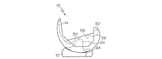
まず図1を参照すると、一実施形態では、後方安定型膝関節用整形外科プロテーゼ10が、脛骨インサートまたはベアリング12と、大腿骨構成要素14と、脛骨トレー15と、を含む。大腿骨構成要素14は、使用中、脛骨ベアリング12と関節接合するように構成されている。脛骨ベアリング12は、例証的には、超高分子量ポリエチレン(UHMWPE)などのポリマー材料から形成されるが、他の実施形態では、セラミック材料、金属材料、生物工学によって作られた材料、または同種のものなど、他の材料から形成されてもよい。大腿骨構成要素12および脛骨トレー15は、例証的には、コバルトクロムまたはチタンなどの金属材料から形成されるが、他の実施形態では、セラミック材料、ポリマー材料、生物工学によって作られた材料、または同種のものなど、他の材料から形成されてもよい。
Referring first to FIG. 1, in one embodiment, a posterior stable knee joint
以下でさらに詳細に論じるように、大腿骨構成要素14は、脛骨ベアリング12と関節接合するように構成され、脛骨ベアリング12は、脛骨トレー15と連結されるように構成されている。例証的な脛骨ベアリング12は、回転する脛骨ベアリングまたは可動性脛骨ベアリングとして具体化されており、使用中、脛骨トレー15に対して回転するように構成されている。しかしながら、他の実施形態では、脛骨ベアリング12は、脛骨トレー15に対して回転するのを制限または禁止されうる、固定された脛骨ベアリングとして具体化されることができる。
As discussed in more detail below, the
脛骨トレー15は、患者の脛骨の、外科的に準備された近位端部(不図示)に固定されるように構成されている。脛骨トレー15は、骨接着剤または他の取付手段を使用して、患者の脛骨に固定されうる。脛骨トレー15は、上部表面82および下部表面84を有するプラットホーム80を含む。例証的には、上部表面82は、概して平坦であり、いくつかの実施形態では、非常に光沢のあるものであってよい。脛骨トレー15は、プラットホーム80の下部表面84から下方に延びるステム86も含む。空洞部またはボア88が、プラットホーム80の上部表面82に画定されて、ステム86内へと下方に延びている。ボア88は、以下でより詳細に論じるように、脛骨インサート12の相補的なステムを受容するように形成されている。
The tibial tray 15 is configured to be secured to a surgically prepared proximal end (not shown) of the patient's tibia. The tibial tray 15 can be secured to the patient's tibia using bone adhesive or other attachment means. The tibial tray 15 includes a
前述のとおり、脛骨ベアリング12は、脛骨トレー15と連結されるように構成されている。脛骨ベアリング12は、上側ベアリング表面18および下部表面20を有するプラットホーム16を含む。脛骨ベアリング12が、回転する脛骨ベアリングまたは可動性脛骨ベアリングとして具体化される、例証的な実施形態では、ベアリング12は、プラットホーム16の下部表面20から下方に延びるステム22を含む。脛骨ベアリング12が脛骨トレー15に連結されると、ステム22は、脛骨トレー15のボア88に受容される。使用の際、脛骨ベアリング12は、ステム22により定められた軸の周りで、脛骨トレー15に対して回転するように構成されている。脛骨ベアリング15が、固定された脛骨ベアリングとして具体化される実施形態では、ベアリング12は、ステム22を含んでも含まなくてもよく、かつ/または、回転しない構成で脛骨ベアリング12を脛骨トレー15に固定するための、他の装置もしくは特徴部を含みうる。
As described above, the
脛骨ベアリング12の上側ベアリング表面18は、内側ベアリング表面24、外側ベアリング表面26、およびプラットホーム16から上向きに延びる突起30を含む。内側ベアリング表面24および外側ベアリング表面26は、以下でより詳細に論じるように、大腿骨構成要素14の、対応する内側顆44および外側顆46を受容するか、または別様にこれらの顆に接触するように、構成されている。したがって、ベアリング表面24、26は、いくつかの実施形態では、凹状の輪郭を有しうる。突起30は、ベアリング表面24、26間に位置付けられ、前方側面32および後方側面34を含む。
The upper bearing surface 18 of the
大腿骨構成要素14は、患者の大腿骨の遠位端部の、外科的に準備された表面(不図示)に連結されるように構成されている。大腿骨構成要素14は、骨接着剤または他の取付手段を用いて、患者の大腿骨に固定されることができる。大腿骨構成要素14は、一対の離間した内側顆44および外側顆46を有する、関節接合表面40を含む。使用の際、顆44、46は、患者の大腿骨の自然の顆に取って代わり、脛骨ベアリング12のプラットホーム16の、対応するベアリング表面24、26上で関節接合するように構成されている。
The
顆44、46は、顆44、46間に顆間ノッチまたは凹部42を画定するように離間している。後方カム50および前方カム52(図2を参照)が、顆間ノッチ42に位置付けられている。後方カム50は、大腿骨構成要素14の後ろ側の方を向いて位置しており、図4〜図13に例示され、また図4〜図13に関して以下でより詳細に説明されるように、屈曲の間、脛骨ベアリング12の突起30に係合するか、または別様に接触するように構成されている。
The
次に図2〜図5を参照すると、大腿骨構成要素14の後方カム50、および脛骨ベアリング12の突起30のそれぞれは、矢状面において、実質的に「S」字型の断面外形を有する。詳細には、図2に示されるように、大腿骨構成要素14の後方カム50は、使用中に、突起30のカム面60に接触するように構成されたカム面54を含む。カム面60に接触するために、後方カム50のカム面54は、凹状カム面56、および凸状カム面58を含む。例証的な実施形態では、凸状カム面58は、凹状カム面56に対して後方に位置付けられている。カム面56、58は、類似の、または異なる曲率半径を有することができる。例えば、いくつかの実施形態では、凸状カム面58は、凹状カム面56の曲率半径よりも実質的に大きい曲率半径を有しうる。しかしながら、他の実施形態では、凸状カム面58は、凹状カム面56の曲率半径に実質的に等しいか、もしくはそれより小さい曲率半径を有することができる。
2-5, each of the
いくつかの実施形態では、カム面56、58の曲率は、単一の曲率半径により定められうる。カム面56、58の特定の曲率半径(すなわち、カム面の「サイズ」)は、インプラントのサイズ、脛骨インプラント12の突起30の関節接合表面の形状もしくは幾何学的外形、および/または同種のものなどの、いくつかの基準によって決まることができる。しかしながら、他の実施形態では、大腿骨構成要素14の凹状カム面56および凸状カム面58は、複数の曲率半径から形成されることができる。例えば、図4に例示される実施形態では、凹状カム面56は、曲率半径200および曲率半径202により定められ、曲率半径200、202のそれぞれは、もう一方に接している(tangent)。特定の一実施形態では、曲率半径200は、約10.42mmであり、曲率半径202は、約8.13mmである。加えて、凸状カム面58は、複数の曲率半径204、206、208、および210により定められる。曲率半径204、206、208、210のそれぞれは、隣接する各曲率半径と接している。特定の一実施形態では、曲率半径204は約7.14mmであり、曲率半径206は約7.01mmであり、曲率半径208は約7.30mmであり、曲率半径210は約2.30mmである。他の実施形態では、より多いか、またはより少ない数の曲率半径が、カム面56、58を定めるのに用いられてよい。加えて、曲率半径200、202、204、206、208、210は、他の実施形態では、他の値を有しうる。
In some embodiments, the curvature of the cam surfaces 56, 58 can be defined by a single radius of curvature. The specific radius of curvature of the cam surfaces 56, 58 (ie, the “size” of the cam surface) is the size of the implant, the shape or geometrical shape of the articulating surface of the
次に図3を参照すると、脛骨ベアリング12のカム面60は、突起30の後方側面34に定められている。大腿骨構成要素14の後方カム50のカム面54と同様に、突起30のカム面60は、凸状カム面62、および凹状カム面64を含む。例証的な実施形態では、凸状カム面62は、凹状カム面64に対して上方に位置付けられている。後方カム50のカム面56、58と同様に、突起30のカム面62、64は、類似の、または異なる曲率半径を有しうる。例えば、いくつかの実施形態では、凹状カム面64は、凸状カム面62の曲率半径よりも実質的に大きい曲率半径を有する。しかしながら、他の実施形態では、凹状カム面64は、凸状カム面62の曲率半径に実質的に等しいか、またはそれより小さい曲率半径を有しうる。
Referring now to FIG. 3, the
いくつかの実施形態では、カム面62、64の曲率は、単一の曲率半径により定められうる。カム面62、64の特定の曲率半径(すなわち、カム面の「サイズ」)は、インプラントのサイズ、大腿骨構成要素14の後方カム50の関節接合表面の形状もしくは幾何学的外形、および/または同種のものなどの、いくつかの基準によって決まることができる。しかしながら、他の実施形態では、脛骨ベアリング12の凸状カム面62および凹状カム面64は、複数の曲率半径から形成されうる。例えば、図5に例示される実施形態では、凹状カム面64は、曲率半径220および曲率半径222により定められており、曲率半径220、222のそれぞれは、もう一方に接している。特定の一実施形態では、曲率半径220は約9.00mmであり、曲率半径222は約13.00mmである。凸状カム面62は、曲率半径224により定められる。特定の一実施形態では、曲率半径224は約8.00mmである。当然、他の実施形態では、より多いか、またはより少ない数の曲率半径が、カム面62、64を定めるのに使用されうる。加えて、曲率半径220、222、224は、他の実施形態では、他の値を有しうる。
In some embodiments, the curvature of the cam surfaces 62, 64 can be defined by a single radius of curvature. The particular radius of curvature of the cam surfaces 62, 64 (ie, the “size” of the cam surface) is dependent on the size of the implant, the shape or geometry of the articulating surface of the
次に図6〜図15を参照すると、大腿骨構成要素14および脛骨ベアリング12は、大腿骨構成要素14の後方カム50が、屈曲中に脛骨ベアリング12の突起30に接触するように、構成されている。詳細には、初期屈曲(early flexion)中は、後方カム50の凹状カム面56は、突起30の凸状カム面62に接触する。整形外科プロテーゼ10の屈曲が増大すると、後方カム50と突起30との間の接触は、後期屈曲(late flexion)中には、後方カム50の凹状カム面56と突起30の凸状カム面62との間の接触から、後方カム50の凸状カム面58と突起30の凹状表面64との間の接触に推移する。
6-15, the
図6に示されるように、整形外科プロテーゼ10が伸展しているか、または別様に屈曲していない(例えば、約0°の屈曲)場合、後方カム50は、突起30と接触していない。しかしながら、図7および図8に例示されるような初期屈曲中、大腿骨構成要素14の後方カム50は、脛骨ベアリング12の突起30に接触する。例えば、図7に例示されるような一実施形態では、整形外科プロテーゼ10が屈曲した状態で動くと、後方カム50の凹状カム面56は、最初に、予め決められた屈曲度で、突起の凸状カム面62に接触する。例証的な実施形態では、大腿骨構成要素14および脛骨ベアリング12は、カム面56、62が屈曲約60度で最初に互いに接触するように、構成されている。しかしながら、他の実施形態では、後方カム50と突起30との間の最初の屈曲が確立される屈曲度は、整形外科プロテーゼ10のサイズ、大腿骨構成要素14および/もしくは脛骨ベアリング12の関節接合表面の形状もしくは幾何学的外形、ならびに/または同種のものなどの特定の基準に基づいて決定されることができる。
As shown in FIG. 6, the
整形外科プロテーゼ10の初期屈曲中、凹状カム面56と凸状カム面62との間の接触は、維持される。例えば、図8に示されるような一実施形態では、突起30の凸状カム面62は、屈曲約60度で、後方カム50の凹状カム面56において完全に「播種(seeded)」されうる。初期屈曲の後、後方カム50と突起30との間の接触は、カム面56、62からカム面58、64へと推移する。例えば、図9に例示されるような一実施形態では、後方カム50と突起30との間の接触は、約80°でカム面58、64へ推移し始める。この屈曲度において、後方カム50の凸状カム面58と突起30の凹状カム面64との間の最初の接触が確立されうる。
During the initial bending of the
整形外科プロテーゼ10の後期屈曲中、凸状カム面58は、凹状カム面64との接触を維持する。例えば、図10〜図15は、様々な後期屈曲度(various degrees of late flexion)における一実施形態を例示している。詳細には、整形外科プロテーゼ10は、図10では屈曲約100度、図11では屈曲約110度、図12では屈曲約120度、図13では屈曲約130度、図14では屈曲約140度、そして図15では屈曲約150度で、例示されている。
During late bending of the
後方カム50と突起30との間の接触は、初期および後期屈曲の範囲全体にわたり維持されることが認識されるべきである。整形外科プロテーゼ10の初期屈曲の特定の範囲(すなわち、後方カム50の凹状カム面56が突起30の凸状カム面62に接触する範囲)および後期屈曲の特定の範囲(すなわち、後方カム50の凸状カム面58が突起30の凹状カム面64に接触する範囲)は、整形外科プロテーゼ10のサイズ、脛骨ベアリング12および大腿骨構成要素14の関節接合するカム面の形状もしくは幾何学的外形、または同種のものなど、1つ以上の基準によって決まることができる。例証的な実施形態では、整形外科プロテーゼ10は、約50°〜約80°の初期屈曲範囲、および約80°〜約150°の後期屈曲範囲を有するように構成されるが、他の実施形態では、他の屈曲範囲が用いられてよい。整形外科プロテーゼ10の初期および後期屈曲範囲は、一つには、カム面56、58、62、64の曲率半径に基づいて決定される。したがって、整形外科プロテーゼ10の初期および後期屈曲範囲は、カム面56、58、62、64の曲率半径を調節することにより構成されうる。
It should be appreciated that contact between the
後方カム50のカム面54が凹状カム面56および凸状カム面58を含み、突起30のカム面34が凸状カム面62および凹状カム面64を含むので、後方カム50と突起30との間の接触表面積は、後方カムおよび/あるいは突起が平坦なカム面、または凹状もしくは凸状表面のみを有するカム面を含む整形外科プロテーゼに比べて、屈曲範囲全体で増大することも、認識されるべきである。例えば、後方カム50と突起30との間の接触面積は、後方カム50の凹状カム面56と突起30の凸状カム面62との間の界面のため、初期屈曲において増大される。加えて、後期屈曲では、後方カム50と突起30との間の接触面積は、後方カム50の凸状カム面58と突起30の凹状カム面64との間の界面のため、後期屈曲度(later degrees of flexion)において増大される。後方カム50と突起30との間の接触がより大きな接触面積にわたって広がるので、突起30の前方磨耗(anterior wear)も減少されうる。
Since the
次に図16および図17を参照すると、いくつかの実施形態では、突起30の後方側面34は、横断面において湾曲していてもよい。すなわち、上方凸状カム面62および下方凹状カム面64のそれぞれは、横断面方向において凸状であってよい。例えば、図16に例示されるように、突起30の凸状カム面62は、横断面において凸状に湾曲していてよい。加えて、図17に例示されるように、突起30の凹状カム面64は、横断面において凸状に湾曲していてよい。凸状カム面62および凹状カム面64の横断面における曲率半径は、実質的に等しいか、または異なってよい。例えば、いくつかの実施形態では、凹状カム面64の横断面における曲率半径は、凸状カム面62の横断面における曲率半径より大きくてよい。代わりに、他の実施形態では、凸状カム面62の横断面における曲率半径は、凸状カム面64の横断面における曲率半径より大きくてよい。
Referring now to FIGS. 16 and 17, in some embodiments, the
突起30のカム面62、64が横断面において湾曲している実施形態では、大腿骨構成要素12の後方カム50は、横断面においてカム面62、64上で関節接合し、大腿骨構成要素14が、突起30の周りで、ある量だけ回転する。例えば、図18および図19に例示されるように、後方カム50の凹状カム面56が初期屈曲中に突起30の凸状カム面62と接触している場合、大腿骨構成要素14は、矢印70で示されるように、横断面において概ね内側‐外側方向に突起30の周りで回転することができる。そのような実施形態では、後方カム50の凹状カム面56は、いくつかの実施形態では、内側‐外側方向において実質的に平坦であってよい。代わりに、突起30の凸状カム面62と同様に、大腿骨構成要素12の後方カム50の凹状カム面56も、内側‐外側方向に湾曲していてもよい。例えば、図19に例示されるように、凹状カム面56は、内側‐外側方向において凹状に湾曲していてよい。いくつかの実施形態では、凹状カム面56の内側‐外側方向における曲率半径は、突起30の凸状カム面62の横断面における曲率半径に実質的に等しくてよい。代わりに、凹状カム面56の内側‐外側方向における曲率半径は、凸状カム面62の横断面における曲率半径より大きいか、または小さくてよい。初期屈曲中の大腿骨構成要素14と脛骨ベアリング12との間の回転の量は、カム面56、62の横断面における曲率半径に基づいて調節されうる。例えば、整形外科プロテーゼの初期屈曲中の回転量の増加は、凸状カム面62の横断面における曲率半径を減少させることにより得ることができる。
In embodiments where the cam surfaces 62, 64 of the
次に図20および図21を参照すると、後方カム50の凸状カム面58が、後期屈曲中に突起30の凹状カム面64と接触している場合、大腿骨構成要素14は、いくつかの実施形態では、矢印72で示されるように、横断面において概ね内側−外側の方向に突起30の周りで回転することができる。そのような実施形態では、後方カム50の凸状カム面58は、内側‐外側方向において実質的に平坦であってよい。代わりに、突起30の凹状カム面64と同様に、大腿骨構成要素12の後方カム50の凸状カム面58は、内側‐外側方向において湾曲していてよい。例えば、図21に例示されるように、凸状カム面58は、内側‐外側方向において凹状に湾曲していてよい。いくつかの実施形態では、凸状カム面58の内側‐外側方向における曲率半径は、突起30の凹状カム面64の内側‐外側方向における曲率半径に実質的に等しくてよい。代わりに、凸状カム面58の内側‐外側方向における曲率半径は、凹状カム面64の内側‐外側方向における曲率半径より大きいか、またはわずかに小さくてよい。初期屈曲について前述したように、後期屈曲中の大腿骨構成要素14と脛骨ベアリング12との間の回転の量は、カム面58、64の内側‐外側方向における曲率半径に基づいて調節されうる。
Referring now to FIGS. 20 and 21, when the
前記のとおり、例証的な整形外科プロテーゼ10の後期屈曲の範囲は、初期屈曲の範囲より大きい。しかしながら、他の実施形態では、整形外科プロテーゼ10は、後期屈曲の範囲よりも大きい、初期屈曲の範囲を有しうる。すなわち、整形外科プロテーゼの初期および後期屈曲の範囲は、一つには、カム面56、58、62、64の曲率半径に基づいて決定されるので、初期および後期屈曲の範囲は、カム面56、58、62、64の曲率半径(すなわち、カム面の「サイズ」)を変えることにより調節されうる。例えば、図22〜図28に例示されるように、別の実施形態では、整形外科プロテーゼ10は、後期屈曲(すなわち、後方カム50の凸状カム面が突起30の凹状カム面に接触する範囲)より大きい、初期屈曲範囲(すなわち、後方カム50の凹状カム面が突起30の凸状カム面に接触する範囲)を含むことができる。
As noted above, the range of late bending of the exemplary
そのような実施形態では、図22〜図24に例示されるように、大腿骨構成要素14の後方カム50は、使用中、突起30のカム面102に接触するように構成されたカム面100を含む。カム面102に接触するために、後方カム50のカム面100は、凹状カム面104、および凸状カム面106を含む。例証的な実施形態では、凸状カム面106は、凹状カム面104に対して後方に位置付けられている。凹状カム面104は、凸状カム面106の曲率半径より実質的に大きな曲率半径を有する。カム面56、58について前述したとおり、カム面104、106の特定の曲率半径(すなわち、カム面の「サイズ」)は、インプラントのサイズ、大腿骨構成要素14および/もしくは脛骨ベアリング12の関節接合表面の形状もしくは幾何学的外形、ならびに/または同種のものなどのいくつかの基準によって決まることができる。特定の一実施形態では、凹状カム面104は約12.7mmの曲率半径を有し、凸状カム面106は約6.4mmの曲率半径を有する。
In such embodiments, as illustrated in FIGS. 22-24, the
大腿骨構成要素14の後方カム50のカム面100と同様に、突起30のカム面102は、凸状カム面108、および凹状カム面110を含む。例証的な実施形態では、凸状カム面108は、凹状カム面110に対して上方に位置付けられている。凸状カム面108は、凹状カム面110の曲率半径より実質的に大きな曲率半径を有する。ここでも、カム面108、110の特定の曲率半径(すなわち、カム面の「サイズ」)は、インプラントのサイズ、患者の解剖学的構造、および/または同種のものなどのいくつかの基準によって決まることができる。特定の一実施形態では、凸状カム面108は、約10.3mmの曲率半径を有し、凹状カム面110は、約1.00mmの曲率半径を有する。
Similar to the
カム面104、108の曲率半径がカム面106、110の曲率半径より大きいので、図22〜図28に例示される整形外科プロテーゼ10の実施形態の初期屈曲の範囲は、後期屈曲の範囲より大きい。例えば、図25に示されるように、整形外科プロテーゼ10が伸展しているか、または別様に、屈曲していない(例えば、約0°の屈曲)場合、後方カム50は、突起30と接触していない。しかしながら、図26に例示されるような初期屈曲の間、大腿骨構成要素14の後方カム50は、脛骨ベアリング12の突起30に接触する。すなわち、初期屈曲中、後方カム50の凹状カム面104は、突起30の凸状カム面108に接触する。カム面104、108の曲率半径は増大しているので、カム面104、108は、より大きな屈曲範囲にわたって、互いと接触した状態を維持する。したがって、整形外科プロテーゼの初期屈曲の範囲は、カム面104、108の曲率半径が減少されている実施形態と比べて増大している。初期屈曲の後、後方カム50と突起30との間の接触は、カム面104、108からカム面106、110へと推移する。例えば、図27に例示されるような一実施形態では、後方カム50と突起30との間の接触は、カム面106、110へ推移し始める。この屈曲度において、後方カム50の凸状カム面106と突起30の凹状カム面110との間の最初の接触が確立されうる。その後、整形外科プロテーゼ10の後期屈曲中、凸状カム面106は、図28に例示されるように、凹状カム面110との接触を維持する。
Since the radius of curvature of the cam surfaces 104, 108 is greater than the radius of curvature of the cam surfaces 106, 110, the range of initial bends in the embodiment of the
ここでも、後方カム50と突起30との間の接触は、初期および後期屈曲の範囲全体にわたって維持されることが認識されるべきである。整形外科プロテーゼ10の初期屈曲の特定の範囲(すなわち、後方カム50の凹状カム面104が突起30の凸状カム面108に接触する範囲)、および後期屈曲の特定の範囲(すなわち、後方カム50の凸状カム面106が突起30の凹状カム面110に接触する範囲)は、整形外科プロテーゼ10のサイズ、患者の解剖学的構造、または同種のものなど、1つ以上の基準によって決まることができる。図22〜図28の例証的な実施形態では、整形外科プロテーゼは、約50°〜約100°の初期屈曲範囲、および約100°〜約150°の後期屈曲範囲を有するように構成されるが、他の実施形態では、他の屈曲範囲が用いられうる。
Again, it should be appreciated that contact between the
後方カム50のカム面100が、凹状カム面104および凸状カム面106を含み、突起30のカム面102が、凸状カム面108および凹状カム面110を含むので、後方カム50と突起30との間の接触表面積は、後方カムおよび/あるいは突起が平坦なカム面、または凹状もしくは凸状表面のみを有するカム面を含む整形外科プロテーゼに比べて増大することも、認識されるべきである。特に、後方カム50の凹状カム面104、および突起30の凸状カム面108は、それぞれ、大きな曲率半径を有するので、後方カム50と突起30との間の接触面積は、初期屈曲中、増大する。加えて、前記のとおり、後方カム50と突起30との間の接触は、より大きな接触面積にわたって広がっているので、突起30の前方磨耗も減少されうる。
Since the
本開示は、図面および前記の説明において詳細に例示され説明されてきたが、このような例証および説明は、例示的なものとみなされるべきであり、性質が限定的なものとみなされるべきではなく、例証的な実施形態のみが図示され説明されたこと、および本開示の趣旨の範囲内にあるすべての変更および改変は保護されることが望まれること、が理解される。 While this disclosure has been illustrated and described in detail in the drawings and foregoing description, such illustration and description are to be considered exemplary and not restrictive in nature. Rather, it is understood that only exemplary embodiments have been shown and described, and that all changes and modifications that fall within the spirit of the disclosure are desired to be protected.
本明細書で説明された装置および組立体の様々な特徴部から現れる、本開示の複数の利点がある。本開示の装置および組立体の代替的実施形態は、説明された特徴部のすべてを含まなくてもよいが、依然として、そのような特徴部の利点のうち少なくともいくつかから利益を得ることに注意されたい。当業者は、本発明の特徴部のうち1つ以上を組み込み、かつ添付の特許請求の範囲により定められるような本開示の趣旨および範囲に属する、装置および組立体の独自の実行を容易に考案することができるであろう。
〔実施の態様〕
(1) 整形外科プロテーゼにおいて、
脛骨トレーに連結されるように構成された脛骨ベアリングであって、前記脛骨ベアリングは、プラットホーム、および前記プラットホームから上向きに延びる突起を有し、前記突起は、凹状カム面および凸状カムを含む後方側面を有する、脛骨ベアリングと、
前記脛骨ベアリングと関節接合するように構成された大腿骨構成要素であって、前記大腿骨構成要素は、
(i)一対の離間した顆であって、前記顆の間に顆間ノッチを画定している、一対の離間した顆、ならびに、
(ii)前記顆間ノッチに位置付けられた後方カムであって、前記後方カムは、凹状カム面および凸状カム面を含む、後方カム、を含む、
大腿骨構成要素と、
を含み、
前記後方カムの前記凹状カム面は、第1の屈曲範囲の間中、前記突起の前記凸状カム面に接触し、前記後方カムの前記凸状カム面は、第2の屈曲範囲の間中、前記突起の前記凹状カム面に接触する、整形外科プロテーゼ。
(2) 実施態様1に記載の整形外科プロテーゼにおいて、
前記脛骨ベアリングの前記突起の前記凸状カム面は、矢状面において凸状に湾曲しており、前記突起の前記凹状カム面は、前記矢状面において凹状に湾曲している、整形外科プロテーゼ。
(3) 実施態様2に記載の整形外科プロテーゼにおいて、
前記突起の前記凹状カム面および前記凸状カム面は、横断面において凸状に湾曲している、整形外科プロテーゼ。
(4) 実施態様3に記載の整形外科プロテーゼにおいて、
前記突起の前記凹状カム面の前記横断面における曲率半径は、前記突起の前記凸状カム面の前記横断面における曲率半径に実質的に等しい、整形外科プロテーゼ。
(5) 実施態様1に記載の整形外科プロテーゼにおいて、
前記大腿骨構成要素の前記後方カムの前記凹状カム面は、矢状面において凹状に湾曲しており、前記大腿骨構成要素の前記後方カムの前記凸状カム面は、前記矢状面において凸状に湾曲している、整形外科プロテーゼ。
(6) 実施態様5に記載の整形外科プロテーゼにおいて、
前記大腿骨構成要素の前記後方カムの前記凹状カム面および前記凸状カム面は、内側‐外側方向において凹状に湾曲している、整形外科プロテーゼ。
(7) 実施態様1に記載の整形外科プロテーゼにおいて、
前記脛骨ベアリングの前記突起、および前記大腿骨構成要素の前記後方カムは、それぞれ、実質的に「S」字型の断面外形を有する、整形外科プロテーゼ。
(8) 実施態様1に記載の整形外科プロテーゼにおいて、
前記脛骨ベアリングの前記突起の前記凸状カム面は、前記突起の前記凹状カム面に対して上方に位置している、整形外科プロテーゼ。
(9) 実施態様1に記載の整形外科プロテーゼにおいて、
前記第1の屈曲範囲の屈曲度は、前記第2の屈曲範囲の屈曲度より小さい、整形外科プロテーゼ。
(10) 実施態様1に記載の整形外科プロテーゼにおいて、
前記第1の屈曲範囲は、屈曲約50度〜屈曲約80度であり、
前記第2の屈曲範囲は、屈曲約80度〜屈曲約150度である、整形外科プロテーゼ。
(11) 整形外科プロテーゼにおいて、
脛骨トレーに連結されるように構成された脛骨ベアリングであって、前記脛骨ベアリングは、プラットホーム、および前記プラットホームから上向きに延びる突起を有し、前記突起は、矢状面において実質的に「S」字型断面を有する後方カム面を含む、脛骨ベアリングと、
大腿骨の遠位端部の、外科的に準備された表面に連結されるように構成された大腿骨構成要素であって、前記大腿骨構成要素は、後方カムを含み、前記後方カムは、矢状面において実質的に「S」字型断面を有するカム面を含む、大腿骨構成要素と、
を含み、
前記後方カムの前記カム面は、ある屈曲範囲の間中、前記突起の前記後方カム面上で関節接合する、整形外科プロテーゼ。
(12) 後方安定型膝関節用整形外科プロテーゼにおいて、
脛骨トレーに連結されるように構成された脛骨ベアリングであって、前記脛骨ベアリングは、
(i)内側ベアリング表面および外側ベアリング表面を含む、プラットホーム、ならびに、
(ii)前記内側ベアリング表面と前記外側ベアリング表面との間で前記プラットホームから上向きに延びる突起であって、前記突起は、上方カム面および下方カム面を有する後方側面を含み、
(i)前記上方カム面は、矢状面において凸状に湾曲しており、
(ii)前記下方カム面は、前記矢状面において凹状に湾曲しており、
(iii)前記上方カム面および前記下方カム面は、横断面において凸状に湾曲している、
突起、を有する、
脛骨ベアリングと、
大腿骨の遠位端部の、外科的に準備された表面に連結されるように構成された大腿骨構成要素であって、前記大腿骨構成要素は、
(i)前記脛骨ベアリングの前記外側ベアリング表面と関節接合するように構成された外側顆、
(ii)前記内側ベアリング表面と関節接合するように構成された内側顆、ならびに、
(iii)前記外側顆と前記内側顆との間に画定された顆間ノッチに位置付けられた後方カムであって、前記後方カムは、前方カム面および後方カム面を含み、
(i)前記前方カム面は、矢状面において凹状に湾曲しており、
(ii)前記後方カム面は、前記矢状面において凸状に湾曲しており、
(iii)前記前方カム面および前記後方カム面は、内側‐外側方向において凹状に湾曲している、
後方カム、を含む、
大腿骨構成要素と、
を含み、
前記後方カムの前記前方カム面は、最初に、第1の屈曲度で、前記突起の前記上方カム面に接触し、前記後方カムの前記後方カム面は、最初に、前記第1の屈曲度より大きい第2の屈曲度で、前記突起の前記下方カム面に接触する、後方安定型膝関節用整形外科プロテーゼ。
[参考例]
以下、参考例を記載する。
(1) 整形外科プロテーゼにおいて、
脛骨トレーに連結されるように構成された脛骨ベアリングであって、前記脛骨ベアリングは、プラットホーム、および前記プラットホームから上向きに延びる突起を有し、前記突起は、凹状カム面および凸状カムを含む後方側面を有する、脛骨ベアリングと、
前記脛骨ベアリングと関節接合するように構成された大腿骨構成要素であって、前記大腿骨構成要素は、
(i)一対の離間した顆であって、前記顆の間に顆間ノッチを画定している、一対の離間した顆、ならびに、
(ii)前記顆間ノッチに位置付けられた後方カムであって、前記後方カムは、凹状カム面および凸状カム面を含む、後方カム、を含む、
大腿骨構成要素と、
を含み、
前記後方カムの前記凹状カム面は、第1の屈曲範囲の間中、前記突起の前記凸状カム面に接触し、前記後方カムの前記凸状カム面は、第2の屈曲範囲の間中、前記突起の前記凹状カム面に接触し、
前記脛骨ベアリングの前記突起の前記凹状カム面は、第1の曲率半径により定められ、前記突起の前記凸状カム面は、第2の曲率半径により定められ、前記第1の曲率半径は、前記第2の曲率半径とは異なる、整形外科プロテーゼ。
(2) 参考例1に記載の整形外科プロテーゼにおいて、
前記大腿骨構成要素の前記後方カムの前記凹状カム面は、第1の曲率半径により定められ、前記大腿骨構成要素の前記後方カムの前記凸状カム面は、第2の半径により定められ、前記第1の曲率半径は、前記第2の曲率半径とは異なる、整形外科プロテーゼ。
(3) 整形外科プロテーゼにおいて、
脛骨トレーに連結されるように構成された脛骨ベアリングであって、前記脛骨ベアリングは、プラットホーム、および前記プラットホームから上向きに延びる突起を有し、前記突起は、矢状面において実質的に「S」字型断面を有する後方カム面を含む、脛骨ベアリングと、
大腿骨の遠位端部の、外科的に準備された表面に連結されるように構成された大腿骨構成要素であって、前記大腿骨構成要素は、後方カムを含み、前記後方カムは、矢状面において実質的に「S」字型断面を有するカム面を含む、大腿骨構成要素と、
を含み、
前記後方カムの前記カム面は、ある屈曲範囲の間中、前記突起の前記後方カム面上で関節接合し、
前記脛骨ベアリングの前記後方カム面は、前記矢状面において凹状カム面および凸状カム面を含み、前記凹状カム面は、前記矢状面において凹状に湾曲しており、前記凸状カム面は、前記矢状面において凸状に湾曲している、整形外科プロテーゼ。
(4) 参考例3に記載の整形外科プロテーゼにおいて、
前記脛骨ベアリングの前記後方カム面の前記凹状カム面および前記凸状カム面は、横断面において湾曲している、整形外科プロテーゼ。
(5) 参考例4に記載の整形外科プロテーゼにおいて、
前記大腿骨構成要素の前記後方カムの前記カム面は、凹状カム面、および凸状カム面を含み、前記凹状カム面は、前記矢状面において凹状に湾曲しており、前記凸状カム面は、前記矢状面において凸状に湾曲している、整形外科プロテーゼ。
(6) 参考例5に記載の整形外科プロテーゼにおいて、
前記大腿骨構成要素の前記後方カムの前記凹状カム面および前記凸状カム面は、内側‐外側方向において湾曲している、整形外科プロテーゼ。
(7) 参考例6に記載の整形外科プロテーゼにおいて、
前記後方カムの前記凹状カム面は、第1の屈曲範囲の間中、前記突起の前記凸状カム面に接触し、前記後方カムの前記凸状カム面は、第2の屈曲範囲の間中、前記突起の前記凹状カム面に接触する、整形外科プロテーゼ。
(8) 参考例6に記載の整形外科プロテーゼにおいて、
前記大腿骨構成要素の前記後方カムは、横断面において前記脛骨ベアリングの前記突起の周りを回転するように構成されている、整形外科プロテーゼ。
There are a number of advantages of the present disclosure arising from the various features of the devices and assemblies described herein. Note that alternative embodiments of the disclosed devices and assemblies may not include all of the described features, but still benefit from at least some of the advantages of such features. I want to be. Those skilled in the art will readily devise their own implementations of the devices and assemblies that incorporate one or more of the features of the present invention and that fall within the spirit and scope of the present disclosure as defined by the appended claims. Would be able to.
Embodiment
(1) In orthopedic prostheses,
A tibial bearing configured to be coupled to a tibial tray, the tibial bearing having a platform and a protrusion extending upward from the platform, the protrusion including a concave cam surface and a convex cam A tibial bearing having a side;
A femoral component configured to articulate with the tibial bearing, the femoral component comprising:
(I) a pair of spaced condyles, a pair of spaced condyles defining an intercondylar notch between said condyles; and
(Ii) a posterior cam positioned in the intercondylar notch, wherein the posterior cam includes a concave cam surface and a convex cam surface;
A femoral component;
Including
The concave cam surface of the rear cam is in contact with the convex cam surface of the protrusion during the first bending range, and the convex cam surface of the rear cam is during the second bending range. An orthopedic prosthesis that contacts the concave cam surface of the protrusion.
(2) In the orthopedic prosthesis according to embodiment 1,
The orthopedic prosthesis, wherein the convex cam surface of the projection of the tibial bearing is convexly curved in a sagittal plane, and the concave cam surface of the projection is concavely curved in the sagittal plane .
(3) In the orthopedic prosthesis according to
The orthopedic prosthesis, wherein the concave cam surface and the convex cam surface of the protrusion are curved convexly in cross section.
(4) In the orthopedic prosthesis according to embodiment 3,
An orthopedic prosthesis, wherein a radius of curvature in the cross section of the concave cam surface of the protrusion is substantially equal to a radius of curvature in the cross section of the convex cam surface of the protrusion.
(5) In the orthopedic prosthesis according to embodiment 1,
The concave cam surface of the posterior cam of the femoral component is concavely curved at the sagittal surface, and the convex cam surface of the posterior cam of the femoral component is convex at the sagittal surface. An orthopedic prosthesis that is curved in shape.
(6) In the orthopedic prosthesis according to embodiment 5,
The orthopedic prosthesis, wherein the concave cam surface and the convex cam surface of the posterior cam of the femoral component are concavely curved in the medial-lateral direction.
(7) In the orthopedic prosthesis according to embodiment 1,
The orthopedic prosthesis, wherein the protrusion of the tibial bearing and the posterior cam of the femoral component each have a substantially "S" shaped cross-sectional profile.
(8) In the orthopedic prosthesis according to embodiment 1,
The orthopedic prosthesis, wherein the convex cam surface of the protrusion of the tibial bearing is located above the concave cam surface of the protrusion.
(9) In the orthopedic prosthesis according to embodiment 1,
The orthopedic prosthesis, wherein the first bending range has a lower bending degree than the second bending range.
(10) In the orthopedic prosthesis according to embodiment 1,
The first bending range is about 50 degrees of bending to about 80 degrees of bending,
The orthopedic prosthesis, wherein the second bending range is from about 80 degrees to about 150 degrees of bending.
( 11 ) In orthopedic prostheses,
A tibial bearing configured to be coupled to a tibial tray, the tibial bearing having a platform and a protrusion extending upward from the platform, wherein the protrusion is substantially "S" in the sagittal plane. A tibial bearing including a posterior cam surface having a cross-sectional shape;
A femoral component configured to be coupled to a surgically prepared surface at a distal end of the femur, wherein the femoral component includes a posterior cam; A femoral component comprising a cam surface having a substantially “S” shaped cross section in the sagittal plane;
Including
The orthopedic prosthesis, wherein the cam surface of the posterior cam articulates on the posterior cam surface of the protrusion during a range of bends.
( 12 ) In the posterior stable knee joint orthopedic prosthesis,
A tibial bearing configured to be coupled to a tibial tray, the tibial bearing comprising:
(I) a platform comprising an inner bearing surface and an outer bearing surface; and
(Ii) a protrusion extending upward from the platform between the inner bearing surface and the outer bearing surface, the protrusion including a rear side surface having an upper cam surface and a lower cam surface;
(I) The upper cam surface is curved convexly in the sagittal plane,
(ii) The lower cam surface is curved concavely in the sagittal plane,
(Iii) The upper cam surface and the lower cam surface are curved in a convex shape in a cross section.
Having protrusions,
A tibial bearing,
A femoral component configured to be coupled to a surgically prepared surface at a distal end of the femur, the femoral component comprising:
(I) a lateral condyle configured to articulate with the outer bearing surface of the tibial bearing;
(Ii) a medial condyle configured to articulate with the medial bearing surface; and
(Iii) a posterior cam positioned in an intercondylar notch defined between the lateral condyle and the medial condyle, wherein the posterior cam includes an anterior cam surface and a posterior cam surface;
(I) The front cam surface is concavely curved in the sagittal plane,
(Ii) The rear cam surface is curved convexly in the sagittal plane,
(Iii) The front cam surface and the rear cam surface are curved in a concave shape in the inner-outer direction,
Including a rear cam,
A femoral component;
Including
The front cam surface of the rear cam initially contacts the upper cam surface of the protrusion with a first degree of flexion, and the rear cam surface of the rear cam initially has the first degree of flexion. A posterior stable knee joint orthopedic prosthesis that contacts the lower cam surface of the protrusion with a second greater degree of flexion.
[Reference example]
Reference examples are described below.
(1) In orthopedic prostheses,
A tibial bearing configured to be coupled to a tibial tray, the tibial bearing having a platform and a protrusion extending upward from the platform, the protrusion including a concave cam surface and a convex cam A tibial bearing having a side;
A femoral component configured to articulate with the tibial bearing, the femoral component comprising:
(I) a pair of spaced condyles, a pair of spaced condyles defining an intercondylar notch between said condyles; and
(Ii) a posterior cam positioned in the intercondylar notch, wherein the posterior cam includes a concave cam surface and a convex cam surface;
A femoral component;
Including
The concave cam surface of the rear cam is in contact with the convex cam surface of the protrusion during the first bending range, and the convex cam surface of the rear cam is during the second bending range. Contacting the concave cam surface of the protrusion,
The concave cam surface of the projection of the tibial bearing is defined by a first radius of curvature, the convex cam surface of the projection is defined by a second radius of curvature, and the first radius of curvature is the An orthopedic prosthesis that is different from the second radius of curvature.
(2) In the orthopedic prosthesis described in Reference Example 1,
The concave cam surface of the posterior cam of the femoral component is defined by a first radius of curvature, and the convex cam surface of the posterior cam of the femoral component is defined by a second radius; The orthopedic prosthesis, wherein the first radius of curvature is different from the second radius of curvature.
(3) In orthopedic prostheses,
A tibial bearing configured to be coupled to a tibial tray, the tibial bearing having a platform and a protrusion extending upward from the platform, wherein the protrusion is substantially "S" in the sagittal plane. A tibial bearing including a posterior cam surface having a cross-sectional shape;
A femoral component configured to be coupled to a surgically prepared surface at a distal end of the femur, wherein the femoral component includes a posterior cam; A femoral component comprising a cam surface having a substantially “S” shaped cross section in the sagittal plane;
Including
The cam surface of the posterior cam is articulated on the posterior cam surface of the protrusion during a certain bending range;
The posterior cam surface of the tibial bearing includes a concave cam surface and a convex cam surface in the sagittal plane, the concave cam surface is curved in a concave shape in the sagittal plane, and the convex cam surface is An orthopedic prosthesis that is convexly curved in the sagittal plane.
(4) In the orthopedic prosthesis described in Reference Example 3,
The orthopedic prosthesis, wherein the concave cam surface and the convex cam surface of the posterior cam surface of the tibial bearing are curved in cross section.
(5) In the orthopedic prosthesis described in Reference Example 4,
The cam surface of the posterior cam of the femoral component includes a concave cam surface and a convex cam surface, and the concave cam surface is concavely curved in the sagittal plane, and the convex cam surface Is an orthopedic prosthesis that is convexly curved in the sagittal plane.
(6) In the orthopedic prosthesis described in Reference Example 5,
The orthopedic prosthesis, wherein the concave cam surface and the convex cam surface of the posterior cam of the femoral component are curved in a medial-lateral direction.
(7) In the orthopedic prosthesis described in Reference Example 6,
The concave cam surface of the rear cam is in contact with the convex cam surface of the protrusion during the first bending range, and the convex cam surface of the rear cam is during the second bending range. An orthopedic prosthesis that contacts the concave cam surface of the protrusion.
(8) In the orthopedic prosthesis described in Reference Example 6,
The orthopedic prosthesis, wherein the posterior cam of the femoral component is configured to rotate about the protrusion of the tibial bearing in cross-section.
Claims (11)
脛骨トレーに連結されるように構成された脛骨ベアリングであって、前記脛骨ベアリングは、プラットホーム、および前記プラットホームから上向きに延びる突起を有し、前記突起は、凹状カム面および凸状カム面を含む後方側面を有する、脛骨ベアリングと、
前記脛骨ベアリングと関節接合するように構成された大腿骨構成要素であって、前記大腿骨構成要素は、
(i)一対の離間した顆であって、前記顆の間に顆間ノッチを画定している、一対の離間した顆、ならびに、
(ii)前記顆間ノッチに位置付けられた後方カムであって、前記後方カムは、凹状カム面および凸状カム面を含む、後方カム、を含む、
大腿骨構成要素と、
を含み、
前記後方カムの前記凹状カム面は、第1の屈曲範囲の間中、前記突起の前記凸状カム面に接触し、前記後方カムの前記凸状カム面は、第2の屈曲範囲の間中、前記突起の前記凹状カム面に接触し、
前記脛骨ベアリングの前記突起の前記凸状カム面は、矢状面において凸状に湾曲しており、前記突起の前記凹状カム面は、前記矢状面において凹状に湾曲している、整形外科プロテーゼ。 In an orthopedic prosthesis,
A tibial bearing configured to be coupled to a tibial tray, the tibial bearing having a platform and a protrusion extending upward from the platform, the protrusion including a concave cam surface and a convex cam surface A tibial bearing having a posterior aspect;
A femoral component configured to articulate with the tibial bearing, the femoral component comprising:
(I) a pair of spaced condyles, a pair of spaced condyles defining an intercondylar notch between said condyles; and
(Ii) a posterior cam positioned in the intercondylar notch, wherein the posterior cam includes a concave cam surface and a convex cam surface;
A femoral component;
Including
The concave cam surface of the rear cam is in contact with the convex cam surface of the protrusion during the first bending range, and the convex cam surface of the rear cam is during the second bending range. Contacting the concave cam surface of the protrusion,
The orthopedic prosthesis, wherein the convex cam surface of the projection of the tibial bearing is convexly curved in a sagittal plane, and the concave cam surface of the projection is concavely curved in the sagittal plane .
前記突起の前記凹状カム面および前記凸状カム面は、横断面において凸状に湾曲している、整形外科プロテーゼ。 The orthopedic prosthesis according to claim 1,
The orthopedic prosthesis, wherein the concave cam surface and the convex cam surface of the protrusion are curved convexly in cross section.
前記突起の前記凹状カム面の前記横断面における曲率半径は、前記突起の前記凸状カム面の前記横断面における曲率半径に等しい、整形外科プロテーゼ。 The orthopedic prosthesis according to claim 2,
An orthopedic prosthesis, wherein a radius of curvature in the cross section of the concave cam surface of the protrusion is equal to a radius of curvature in the cross section of the convex cam surface of the protrusion.
前記大腿骨構成要素の前記後方カムの前記凹状カム面は、矢状面において凹状に湾曲しており、前記大腿骨構成要素の前記後方カムの前記凸状カム面は、前記矢状面において凸状に湾曲している、整形外科プロテーゼ。 The orthopedic prosthesis according to claim 1,
The concave cam surface of the posterior cam of the femoral component is concavely curved at the sagittal surface, and the convex cam surface of the posterior cam of the femoral component is convex at the sagittal surface. An orthopedic prosthesis that is curved in shape.
前記大腿骨構成要素の前記後方カムの前記凹状カム面および前記凸状カム面は、内側‐外側方向において凹状に湾曲している、整形外科プロテーゼ。 The orthopedic prosthesis according to claim 4,
The orthopedic prosthesis, wherein the concave cam surface and the convex cam surface of the posterior cam of the femoral component are concavely curved in the medial-lateral direction.
前記脛骨ベアリングの前記突起、および前記大腿骨構成要素の前記後方カムは、それぞれ、「S」字型の断面外形を有する、整形外科プロテーゼ。 The orthopedic prosthesis according to claim 1,
The orthopedic prosthesis, wherein the protrusion of the tibial bearing and the posterior cam of the femoral component each have an “S” shaped cross-sectional profile .
前記脛骨ベアリングの前記突起の前記凸状カム面は、前記突起の前記凹状カム面に対して上方に位置している、整形外科プロテーゼ。 The orthopedic prosthesis according to claim 1,
The orthopedic prosthesis, wherein the convex cam surface of the protrusion of the tibial bearing is located above the concave cam surface of the protrusion.
前記第1の屈曲範囲の屈曲度は、前記第2の屈曲範囲の屈曲度より小さい、整形外科プロテーゼ。 The orthopedic prosthesis according to claim 1,
The orthopedic prosthesis, wherein the first bending range has a lower bending degree than the second bending range.
前記第1の屈曲範囲は、屈曲50度〜屈曲80度であり、
前記第2の屈曲範囲は、屈曲80度〜屈曲150度である、整形外科プロテーゼ。 The orthopedic prosthesis according to claim 1,
The first bending range is a bending of 50 degrees to a bending of 80 degrees ,
The orthopedic prosthesis, wherein the second bending range is from 80 degrees to 150 degrees .
脛骨トレーに連結されるように構成された脛骨ベアリングであって、前記脛骨ベアリングは、プラットホーム、および前記プラットホームから上向きに延びる突起を有し、前記突起は、矢状面において「S」字型断面を有する後方カム面を含む、脛骨ベアリングと、
大腿骨の遠位端部の、外科的に準備された表面に連結されるように構成された大腿骨構成要素であって、前記大腿骨構成要素は、後方カムを含み、前記後方カムは、矢状面において「S」字型断面を有するカム面を含む、大腿骨構成要素と、
を含み、
前記後方カムの前記カム面は、ある屈曲範囲の間中、前記突起の前記後方カム面上で関節接合し、
前記突起の前記後方カム面は凹状カム面および凸状カム面を含み、前記突起の前記凸状カム面は、矢状面において凸状に湾曲しており、前記突起の前記凹状カム面は、前記矢状面において凹状に湾曲している、整形外科プロテーゼ。 In an orthopedic prosthesis,
A tibial bearing configured to be coupled to a tibial tray, the tibial bearing having a platform and a protrusion extending upward from the platform, the protrusion having an "S" -shaped cross section in a sagittal plane A tibial bearing including a posterior cam surface having
A femoral component configured to be coupled to a surgically prepared surface at a distal end of the femur, wherein the femoral component includes a posterior cam; A femoral component comprising a cam surface having an “S” shaped cross section in the sagittal plane ;
Including
The cam surface of the posterior cam is articulated on the posterior cam surface of the protrusion during a certain bending range;
The rear cam surface of the projection includes a concave cam surface and a convex cam surface, the convex cam surface of the projection is curved in a sagittal plane, and the concave cam surface of the projection is An orthopedic prosthesis that is concavely curved in the sagittal plane.
脛骨トレーに連結されるように構成された脛骨ベアリングであって、前記脛骨ベアリングは、
(i)内側ベアリング表面および外側ベアリング表面を含む、プラットホーム、ならびに、
(ii)前記内側ベアリング表面と前記外側ベアリング表面との間で前記プラットホームから上向きに延びる突起であって、前記突起は、上方カム面および下方カム面を有する後方側面を含み、
(i)前記上方カム面は、矢状面において凸状に湾曲しており、
(ii)前記下方カム面は、前記矢状面において凹状に湾曲しており、
(iii)前記上方カム面および前記下方カム面は、横断面において凸状に湾曲している、
突起、を有する、
脛骨ベアリングと、
大腿骨の遠位端部の、外科的に準備された表面に連結されるように構成された大腿骨構成要素であって、前記大腿骨構成要素は、
(i)前記脛骨ベアリングの前記外側ベアリング表面と関節接合するように構成された外側顆、
(ii)前記内側ベアリング表面と関節接合するように構成された内側顆、ならびに、
(iii)前記外側顆と前記内側顆との間に画定された顆間ノッチに位置付けられた後方カムであって、前記後方カムは、前方カム面および後方カム面を含み、
(i)前記前方カム面は、矢状面において凹状に湾曲しており、
(ii)前記後方カム面は、前記矢状面において凸状に湾曲しており、
(iii)前記前方カム面および前記後方カム面は、内側‐外側方向において凹状に湾曲している、
後方カム、を含む、
大腿骨構成要素と、
を含み、
前記後方カムの前記前方カム面は、最初に、第1の屈曲度で、前記突起の前記上方カム面に接触し、前記後方カムの前記後方カム面は、最初に、前記第1の屈曲度より大きい第2の屈曲度で、前記突起の前記下方カム面に接触する、後方安定型膝関節用整形外科プロテーゼ。 In an orthopedic prosthesis for the posterior stable knee joint,
A tibial bearing configured to be coupled to a tibial tray, the tibial bearing comprising:
(I) a platform comprising an inner bearing surface and an outer bearing surface; and
(Ii) a protrusion extending upward from the platform between the inner bearing surface and the outer bearing surface, the protrusion including a rear side surface having an upper cam surface and a lower cam surface;
(I) The upper cam surface is curved convexly in the sagittal plane,
(ii) The lower cam surface is curved concavely in the sagittal plane,
(Iii) The upper cam surface and the lower cam surface are curved in a convex shape in a cross section.
Having protrusions,
A tibial bearing,
A femoral component configured to be coupled to a surgically prepared surface at a distal end of the femur, the femoral component comprising:
(I) a lateral condyle configured to articulate with the outer bearing surface of the tibial bearing;
(Ii) a medial condyle configured to articulate with the medial bearing surface; and
(Iii) a posterior cam positioned in an intercondylar notch defined between the lateral condyle and the medial condyle, wherein the posterior cam includes an anterior cam surface and a posterior cam surface;
(I) The front cam surface is concavely curved in the sagittal plane,
(Ii) The rear cam surface is curved convexly in the sagittal plane,
(Iii) The front cam surface and the rear cam surface are curved in a concave shape in the inner-outer direction,
Including a rear cam,
A femoral component;
Including
The front cam surface of the rear cam initially contacts the upper cam surface of the protrusion with a first degree of flexion, and the rear cam surface of the rear cam initially has the first degree of flexion. A posterior stable knee joint orthopedic prosthesis that contacts the lower cam surface of the protrusion with a second greater degree of flexion.
Applications Claiming Priority (2)
| Application Number | Priority Date | Filing Date | Title |
|---|---|---|---|
| US12/165,582 US8206451B2 (en) | 2008-06-30 | 2008-06-30 | Posterior stabilized orthopaedic prosthesis |
| US12/165,582 | 2008-06-30 |
Publications (2)
| Publication Number | Publication Date |
|---|---|
| JP2010012256A JP2010012256A (en) | 2010-01-21 |
| JP5535533B2 true JP5535533B2 (en) | 2014-07-02 |
Family
ID=41350712
Family Applications (1)
| Application Number | Title | Priority Date | Filing Date |
|---|---|---|---|
| JP2009153337A Active JP5535533B2 (en) | 2008-06-30 | 2009-06-29 | Posterior stable orthopedic prosthesis |
Country Status (7)
| Country | Link |
|---|---|
| US (3) | US8206451B2 (en) |
| EP (2) | EP2878283B8 (en) |
| JP (1) | JP5535533B2 (en) |
| CN (1) | CN101683289B (en) |
| AU (1) | AU2009202627B2 (en) |
| DK (1) | DK2149354T3 (en) |
| ES (2) | ES2534653T3 (en) |
Families Citing this family (110)
| Publication number | Priority date | Publication date | Assignee | Title |
|---|---|---|---|---|
| US8771365B2 (en) | 2009-02-25 | 2014-07-08 | Conformis, Inc. | Patient-adapted and improved orthopedic implants, designs, and related tools |
| US8882847B2 (en) | 2001-05-25 | 2014-11-11 | Conformis, Inc. | Patient selectable knee joint arthroplasty devices |
| US8545569B2 (en) | 2001-05-25 | 2013-10-01 | Conformis, Inc. | Patient selectable knee arthroplasty devices |
| US7468075B2 (en) | 2001-05-25 | 2008-12-23 | Conformis, Inc. | Methods and compositions for articular repair |
| US8083745B2 (en) | 2001-05-25 | 2011-12-27 | Conformis, Inc. | Surgical tools for arthroplasty |
| US20040133276A1 (en) | 2002-10-07 | 2004-07-08 | Imaging Therapeutics, Inc. | Minimally invasive joint implant with 3-Dimensional geometry matching the articular surfaces |
| US8735773B2 (en) | 2007-02-14 | 2014-05-27 | Conformis, Inc. | Implant device and method for manufacture |
| US7534263B2 (en) | 2001-05-25 | 2009-05-19 | Conformis, Inc. | Surgical tools facilitating increased accuracy, speed and simplicity in performing joint arthroplasty |
| US8556983B2 (en) | 2001-05-25 | 2013-10-15 | Conformis, Inc. | Patient-adapted and improved orthopedic implants, designs and related tools |
| US9603711B2 (en) | 2001-05-25 | 2017-03-28 | Conformis, Inc. | Patient-adapted and improved articular implants, designs and related guide tools |
| US8480754B2 (en) | 2001-05-25 | 2013-07-09 | Conformis, Inc. | Patient-adapted and improved articular implants, designs and related guide tools |
| US6558426B1 (en) | 2000-11-28 | 2003-05-06 | Medidea, Llc | Multiple-cam, posterior-stabilized knee prosthesis |
| US6719800B2 (en) | 2001-01-29 | 2004-04-13 | Zimmer Technology, Inc. | Constrained prosthetic knee with rotating bearing |
| US6485519B2 (en) | 2001-01-29 | 2002-11-26 | Bristol-Myers Squibb Company | Constrained prosthetic knee with rotating bearing |
| US8951260B2 (en) | 2001-05-25 | 2015-02-10 | Conformis, Inc. | Surgical cutting guide |
| US8439926B2 (en) | 2001-05-25 | 2013-05-14 | Conformis, Inc. | Patient selectable joint arthroplasty devices and surgical tools |
| WO2002096268A2 (en) | 2001-05-25 | 2002-12-05 | Imaging Therapeutics, Inc. | Methods and compositions for articular resurfacing |
| EP3075356B1 (en) | 2002-11-07 | 2023-07-05 | ConforMIS, Inc. | Method of selecting a meniscal implant |
| US9301845B2 (en) | 2005-06-15 | 2016-04-05 | P Tech, Llc | Implant for knee replacement |
| CN101222886B (en) * | 2005-07-14 | 2012-05-30 | 国立大学法人佐贺大学 | Artificial knee joint |
| AU2006325787B2 (en) * | 2005-12-15 | 2013-07-18 | Sergio Romagnoli | Distal femoral knee prostheses |
| US8623026B2 (en) | 2006-02-06 | 2014-01-07 | Conformis, Inc. | Patient selectable joint arthroplasty devices and surgical tools incorporating anatomical relief |
| CA2641241A1 (en) | 2006-02-06 | 2007-08-16 | Conformis, Inc. | Patient selectable joint arthroplasty devices and surgical tools |
| US20110166671A1 (en) | 2006-11-07 | 2011-07-07 | Kellar Franz W | Prosthetic joint |
| US8070823B2 (en) | 2006-11-07 | 2011-12-06 | Biomedflex Llc | Prosthetic ball-and-socket joint |
| US8029574B2 (en) | 2006-11-07 | 2011-10-04 | Biomedflex Llc | Prosthetic knee joint |
| US8308812B2 (en) | 2006-11-07 | 2012-11-13 | Biomedflex, Llc | Prosthetic joint assembly and joint member therefor |
| US8512413B2 (en) | 2006-11-07 | 2013-08-20 | Biomedflex, Llc | Prosthetic knee joint |
| WO2008058205A1 (en) | 2006-11-07 | 2008-05-15 | Biomedflex, Llc | Medical implants |
| US9005307B2 (en) | 2006-11-07 | 2015-04-14 | Biomedflex, Llc | Prosthetic ball-and-socket joint |
| EP2591756A1 (en) | 2007-02-14 | 2013-05-15 | Conformis, Inc. | Implant device and method for manufacture |
| US8128703B2 (en) | 2007-09-28 | 2012-03-06 | Depuy Products, Inc. | Fixed-bearing knee prosthesis having interchangeable components |
| US8632600B2 (en) | 2007-09-25 | 2014-01-21 | Depuy (Ireland) | Prosthesis with modular extensions |
| US9204967B2 (en) | 2007-09-28 | 2015-12-08 | Depuy (Ireland) | Fixed-bearing knee prosthesis having interchangeable components |
| WO2009111626A2 (en) | 2008-03-05 | 2009-09-11 | Conformis, Inc. | Implants for altering wear patterns of articular surfaces |
| JP2011519713A (en) | 2008-05-12 | 2011-07-14 | コンフォーミス・インコーポレイテッド | Devices and methods for treatment of facet joints and other joints |
| US9119723B2 (en) | 2008-06-30 | 2015-09-01 | Depuy (Ireland) | Posterior stabilized orthopaedic prosthesis assembly |
| US8206451B2 (en) | 2008-06-30 | 2012-06-26 | Depuy Products, Inc. | Posterior stabilized orthopaedic prosthesis |
| US8828086B2 (en) | 2008-06-30 | 2014-09-09 | Depuy (Ireland) | Orthopaedic femoral component having controlled condylar curvature |
| US8187335B2 (en) | 2008-06-30 | 2012-05-29 | Depuy Products, Inc. | Posterior stabilized orthopaedic knee prosthesis having controlled condylar curvature |
| US8192498B2 (en) | 2008-06-30 | 2012-06-05 | Depuy Products, Inc. | Posterior cructiate-retaining orthopaedic knee prosthesis having controlled condylar curvature |
| US8236061B2 (en) | 2008-06-30 | 2012-08-07 | Depuy Products, Inc. | Orthopaedic knee prosthesis having controlled condylar curvature |
| US9168145B2 (en) | 2008-06-30 | 2015-10-27 | Depuy (Ireland) | Posterior stabilized orthopaedic knee prosthesis having controlled condylar curvature |
| WO2010099231A2 (en) | 2009-02-24 | 2010-09-02 | Conformis, Inc. | Automated systems for manufacturing patient-specific orthopedic implants and instrumentation |
| US9078755B2 (en) | 2009-02-25 | 2015-07-14 | Zimmer, Inc. | Ethnic-specific orthopaedic implants and custom cutting jigs |
| SG10201401326SA (en) | 2009-04-16 | 2014-10-30 | Conformis Inc | Patient-specific joint arthroplasty devices for ligament repair |
| US9101476B2 (en) | 2009-05-21 | 2015-08-11 | Depuy (Ireland) | Prosthesis with surfaces having different textures and method of making the prosthesis |
| US11213397B2 (en) | 2009-05-21 | 2022-01-04 | Depuy Ireland Unlimited Company | Prosthesis with surfaces having different textures and method of making the prosthesis |
| US8998997B2 (en) | 2009-08-11 | 2015-04-07 | Michael D. Ries | Implantable mobile bearing prosthetics |
| US9095453B2 (en) * | 2009-08-11 | 2015-08-04 | Michael D. Ries | Position adjustable trial systems for prosthetic implants |
| US8568485B2 (en) * | 2009-08-11 | 2013-10-29 | Imds Corporation | Articulating trials for prosthetic implants |
| US8496666B2 (en) | 2009-08-11 | 2013-07-30 | Imds Corporation | Instrumentation for mobile bearing prosthetics |
| US8382848B2 (en) * | 2009-08-11 | 2013-02-26 | Imds Corporation | Position adjustable trial systems for prosthetic implants |
| EP2319460A1 (en) | 2009-10-30 | 2011-05-11 | DePuy Products, Inc. | Prosthesis with cut-off pegs |
| EP2316384B1 (en) | 2009-10-30 | 2013-04-03 | DePuy Products, Inc. | Prosthesis with modular extensions |
| EP2316382B1 (en) | 2009-10-30 | 2014-03-05 | DePuy (Ireland) | Prosthesis for cementless fixation |
| DK2316383T3 (en) | 2009-10-30 | 2013-07-22 | Depuy Products Inc | Prosthesis with surfaces with different textures |
| DK2319462T3 (en) | 2009-10-30 | 2013-07-08 | Depuy Products Inc | Prosthesis with composite component |
| US8900315B2 (en) * | 2009-11-16 | 2014-12-02 | New York Society For The Ruptured And Crippled Maintaining The Hospital For Special Surgery | Constrained condylar knee device |
| WO2011060434A2 (en) * | 2009-11-16 | 2011-05-19 | New York Society For The Ruptured And Crippled Maintaining The Hospital For Special Surgery | Prosthetic condylar joints with articulating bearing surfaces having a translating contact point during rotation thereof |
| AU2010327987B2 (en) | 2009-12-11 | 2015-04-02 | Conformis, Inc. | Patient-specific and patient-engineered orthopedic implants |
| US20110178606A1 (en) | 2010-01-21 | 2011-07-21 | Depuy Products, Inc. | Tibial components for a knee prosthesis system |
| US9011547B2 (en) | 2010-01-21 | 2015-04-21 | Depuy (Ireland) | Knee prosthesis system |
| US8764840B2 (en) | 2010-07-24 | 2014-07-01 | Zimmer, Inc. | Tibial prosthesis |
| CA2806321C (en) * | 2010-07-24 | 2018-08-21 | Zimmer, Inc. | Asymmetric tibial components for a knee prosthesis |
| US9173744B2 (en) | 2010-09-10 | 2015-11-03 | Zimmer Gmbh | Femoral prosthesis with medialized patellar groove |
| EP3348236B1 (en) | 2010-09-10 | 2019-11-20 | Zimmer, Inc. | Motion facilitating tibial components for a knee prosthesis |
| US8317870B2 (en) | 2010-09-30 | 2012-11-27 | Depuy Products, Inc. | Tibial component of a knee prosthesis having an angled cement pocket |
| US8287601B2 (en) * | 2010-09-30 | 2012-10-16 | Depuy Products, Inc. | Femoral component of a knee prosthesis having an angled cement pocket |
| EP2438889B1 (en) * | 2010-10-05 | 2013-12-11 | Aesculap Ag | Knee joint prosthesis |
| JP5688281B2 (en) * | 2010-12-10 | 2015-03-25 | 京セラメディカル株式会社 | Artificial knee joint |
| US8603101B2 (en) | 2010-12-17 | 2013-12-10 | Zimmer, Inc. | Provisional tibial prosthesis system |
| JP6151190B2 (en) * | 2011-01-27 | 2017-06-21 | スミス アンド ネフュー インコーポレイテッド | Tibial insert, prosthesis |
| CN103476363B (en) | 2011-02-15 | 2017-06-30 | 康复米斯公司 | Operation and the instrument of change and/or asymmetry are dissected in improved suitable patient's type joint implant and treatment, assessment, correction, modification and/or adaptation |
| US8932365B2 (en) | 2011-06-16 | 2015-01-13 | Zimmer, Inc. | Femoral component for a knee prosthesis with improved articular characteristics |
| US8551179B2 (en) | 2011-06-16 | 2013-10-08 | Zimmer, Inc. | Femoral prosthesis system having provisional component with visual indicators |
| US9308095B2 (en) | 2011-06-16 | 2016-04-12 | Zimmer, Inc. | Femoral component for a knee prosthesis with improved articular characteristics |
| US9060868B2 (en) | 2011-06-16 | 2015-06-23 | Zimmer, Inc. | Femoral component for a knee prosthesis with bone compacting ridge |
| JP6033860B2 (en) * | 2011-06-30 | 2016-11-30 | デピュイ・(アイルランド)Depuy (Ireland) | Retrostable orthopedic prosthesis assembly |
| JP6472658B2 (en) * | 2011-06-30 | 2019-02-20 | デピュイ・アイルランド・アンリミテッド・カンパニーDepuy Ireland Unlimited Company | Retrostable orthopedic knee prosthesis with controlled condyle curvature |
| CN103997978A (en) | 2011-07-13 | 2014-08-20 | 通用医疗公司 | Methods and devices for knee joint replacement with anterior cruciate ligament substitution |
| BR112014002240B1 (en) * | 2011-09-19 | 2021-05-11 | Tecres S.P.A | Temporary modular spacer device for human body joints |
| US8409293B1 (en) * | 2011-10-26 | 2013-04-02 | Sevika Holding AG | Knee prosthesis |
| WO2013074144A1 (en) | 2011-11-18 | 2013-05-23 | Zimmer, Inc. | Tibial bearing component for a knee prosthesis with improved articular characteristics |
| WO2013077919A1 (en) | 2011-11-21 | 2013-05-30 | Zimmer, Inc. | Tibial baseplate with asymmetric placement of fixation structures |
| EP2809273B1 (en) | 2012-01-30 | 2021-05-05 | Zimmer, Inc. | Asymmetric tibial components for a knee prosthesis |
| FR2989568B1 (en) * | 2012-04-19 | 2014-09-05 | Teknimed | IMPLANT SPACER FOR TEMPORARY REPLACEMENT OF KNEE PROSTHESIS |
| US9675471B2 (en) | 2012-06-11 | 2017-06-13 | Conformis, Inc. | Devices, techniques and methods for assessing joint spacing, balancing soft tissues and obtaining desired kinematics for joint implant components |
| IN2014DE00549A (en) * | 2013-03-07 | 2015-06-12 | Depuy Ireland | |
| US9237953B2 (en) | 2013-03-15 | 2016-01-19 | Depuy (Ireland) | Mechanical assembly of pegs to prosthesis |
| US9925052B2 (en) | 2013-08-30 | 2018-03-27 | Zimmer, Inc. | Method for optimizing implant designs |
| US9144499B2 (en) | 2013-12-17 | 2015-09-29 | Depuy (Ireland) | Low profile mobile/fixed prosthetic knee systems |
| FR3016284B1 (en) * | 2014-01-14 | 2019-08-16 | Evolutis | POSTERO STABILIZED PROSTHESIS OF THE KNEE |
| JP6499674B2 (en) * | 2014-02-10 | 2019-04-10 | リマコーポレート・ソチエタ・ペル・アチオニLimacorporate S.P.A. | Artificial knee joint |
| US10130375B2 (en) | 2014-07-31 | 2018-11-20 | Zimmer, Inc. | Instruments and methods in performing kinematically-aligned total knee arthroplasty |
| KR101696608B1 (en) * | 2014-11-07 | 2017-01-17 | 주식회사 코렌텍 | Artifical Knee Joint preventing Dislocation of Femoral Component |
| CN105030382A (en) * | 2015-02-10 | 2015-11-11 | 江苏奥康尼医疗科技发展有限公司 | Organic polymer material dual-slide artificial knee joint |
| CN104887354B (en) * | 2015-02-10 | 2017-06-30 | 江苏奥康尼医疗科技发展有限公司 | A kind of combined type high-molecular organic material artificial knee joint |
| CN108135701B (en) | 2015-09-21 | 2019-12-24 | 捷迈有限公司 | Prosthesis system including tibial bearing component |
| EP3355834B1 (en) | 2015-09-29 | 2023-01-04 | Zimmer, Inc. | Tibial prosthesis for tibia with varus resection |
| CN105213071A (en) * | 2015-10-21 | 2016-01-06 | 苏州锐进医疗科技有限公司 | A kind of bone conservative knee-joint prosthesis |
| CN106580524B (en) * | 2016-12-12 | 2018-08-07 | 上海昕健医疗技术有限公司 | Posterior stabilized knee prosthesis |
| US10675153B2 (en) | 2017-03-10 | 2020-06-09 | Zimmer, Inc. | Tibial prosthesis with tibial bearing component securing feature |
| CA3063415C (en) | 2017-05-12 | 2021-10-19 | Zimmer, Inc. | Femoral prostheses with upsizing and downsizing capabilities |
| CN107280812A (en) * | 2017-07-18 | 2017-10-24 | 优适医疗科技(苏州)有限公司 | A kind of artificial knee joint prosthesis |
| CN107468381A (en) * | 2017-08-02 | 2017-12-15 | 浙江德康医疗器械有限公司 | A kind of knee joint system |
| US11426282B2 (en) | 2017-11-16 | 2022-08-30 | Zimmer, Inc. | Implants for adding joint inclination to a knee arthroplasty |
| US10835380B2 (en) | 2018-04-30 | 2020-11-17 | Zimmer, Inc. | Posterior stabilized prosthesis system |
| US11382757B1 (en) * | 2020-01-15 | 2022-07-12 | Lento Medical, Inc. | Condylar asymmetry knee prosthesis |
| US11357634B1 (en) * | 2020-01-15 | 2022-06-14 | Lento Medical, Inc. | Posterior-stabilized symmetric knee prosthesis |
Family Cites Families (341)
| Publication number | Priority date | Publication date | Assignee | Title |
|---|---|---|---|---|
| GB1065354A (en) | 1964-04-13 | 1967-04-12 | Gen Electric | Improvements in fortification of anodized surfaces |
| CA962806A (en) | 1970-06-04 | 1975-02-18 | Ontario Research Foundation | Surgical prosthetic device |
| US3765033A (en) | 1971-01-19 | 1973-10-16 | D Goldberg | Prosthetic knee joint assembly with mutually slidable and rollable joint sections |
| US3852045A (en) | 1972-08-14 | 1974-12-03 | Battelle Memorial Institute | Void metal composite material and method |
| GB1448818A (en) * | 1972-09-18 | 1976-09-08 | Nat Res Dev | Prosthetic knee joint devices |
| US3869731A (en) | 1973-02-14 | 1975-03-11 | Univ California | Articulated two-part prosthesis replacing the knee joint |
| US3938226A (en) * | 1974-03-13 | 1976-02-17 | Kling-Tecs, Inc. | Apparatus for crimping yarn |
| GB1550010A (en) | 1976-12-15 | 1979-08-08 | Ontario Research Foundation | Surgical prosthetic device or implant having pure metal porous coating |
| US4081866A (en) | 1977-02-02 | 1978-04-04 | Howmedica, Inc. | Total anatomical knee prosthesis |
| US4156943A (en) | 1977-08-24 | 1979-06-05 | Collier John P | High-strength porous prosthetic device and process for making the same |
| US4209861A (en) | 1978-02-22 | 1980-07-01 | Howmedica, Inc. | Joint prosthesis |
| US4470158A (en) | 1978-03-10 | 1984-09-11 | Biomedical Engineering Corp. | Joint endoprosthesis |
| DE2965891D1 (en) | 1978-03-10 | 1983-08-25 | Biomedical Eng Corp | Improved joint endoprosthesis |
| CH632151A5 (en) * | 1978-10-06 | 1982-09-30 | Sulzer Ag | ENDOPROTHESIS FOR A KNEE JOINT. |
| US4215439A (en) | 1978-10-16 | 1980-08-05 | Zimmer, USA | Semi-restraining knee prosthesis |
| US4257129A (en) | 1979-05-21 | 1981-03-24 | Volz Robert G | Prosthetic knee joint tibial implant |
| US4340978A (en) | 1979-07-02 | 1982-07-27 | Biomedical Engineering Corp. | New Jersey meniscal bearing knee replacement |
| US4262368A (en) | 1979-09-24 | 1981-04-21 | Wright Manufacturing Company | Rotating and hinged knee prosthesis |
| US5037423A (en) | 1983-10-26 | 1991-08-06 | Pfizer Hospital Products Group, Inc. | Method and instrumentation for the replacement of a knee prosthesis |
| US4944760A (en) | 1983-10-26 | 1990-07-31 | Pfizer Hospital Products Group, Inc. | Method and instrumentation for the replacement of a knee prosthesis |
| US4612160A (en) | 1984-04-02 | 1986-09-16 | Dynamet, Inc. | Porous metal coating process and mold therefor |
| SE450336B (en) | 1984-11-28 | 1987-06-22 | Branemark Per Ingvar | LED PROTES FOR PERMANENT ANCHORING IN THE BONE TISSUE |
| US4673407A (en) | 1985-02-20 | 1987-06-16 | Martin Daniel L | Joint-replacement prosthetic device |
| US5201766A (en) | 1985-09-11 | 1993-04-13 | Smith & Nephew Richards Inc. | Prosthetic device with porous matrix and method of manufacture |
| US4808185A (en) | 1986-02-07 | 1989-02-28 | Penenberg Brad L | Tibial prosthesis, template and reamer |
| US4714474A (en) | 1986-05-12 | 1987-12-22 | Dow Corning Wright Corporation | Tibial knee joint prosthesis with removable articulating surface insert |
| US4963152A (en) | 1986-10-27 | 1990-10-16 | Intermedics Orthopedics, Inc. | Asymmetric prosthetic tibial component |
| US4822362A (en) | 1987-05-19 | 1989-04-18 | Walker Peter S | Process and apparatus for tibial plateau compenent |
| FR2621243A1 (en) | 1987-10-06 | 1989-04-07 | Cuilleron J | Total knee prothesis |
| US4795468A (en) | 1987-12-23 | 1989-01-03 | Zimmer, Inc. | Mechanism and method for locking a bearing insert to the base of a prosthetic implant |
| US4888021A (en) * | 1988-02-02 | 1989-12-19 | Joint Medical Products Corporation | Knee and patellar prosthesis |
| US5011496A (en) | 1988-02-02 | 1991-04-30 | Joint Medical Products Corporation | Prosthetic joint |
| US4950298A (en) | 1988-04-08 | 1990-08-21 | Gustilo Ramon B | Modular knee joint prosthesis |
| US4944757A (en) | 1988-11-07 | 1990-07-31 | Martinez David M | Modulator knee prosthesis system |
| US5007933A (en) | 1989-01-31 | 1991-04-16 | Osteonics Corp. | Modular knee prosthesis system |
| US4990163A (en) | 1989-02-06 | 1991-02-05 | Trustees Of The University Of Pennsylvania | Method of depositing calcium phosphate cermamics for bone tissue calcification enhancement |
| US4938769A (en) | 1989-05-31 | 1990-07-03 | Shaw James A | Modular tibial prosthesis |
| GB8912682D0 (en) | 1989-06-02 | 1989-07-19 | Thackray Chas F | Improvements in and relating to knee prosthesis |
| US5171283A (en) | 1989-07-11 | 1992-12-15 | Biomedical Engineering Trust | Compound shape rotating bearing |
| FR2653992B1 (en) | 1989-11-09 | 1998-01-23 | Richard Berakassa | TOTAL SLIDING KNEE PROSTHESIS. |
| US5019103A (en) | 1990-02-05 | 1991-05-28 | Boehringer Mannheim Corporation | Tibial wedge system |
| US5147405A (en) | 1990-02-07 | 1992-09-15 | Boehringer Mannheim Corporation | Knee prosthesis |
| GB9005496D0 (en) | 1990-03-12 | 1990-05-09 | Howmedica | Tibial component for a replacement knee prosthesis and total knee prosthesis incorporating such a component |
| US5358531A (en) | 1990-06-12 | 1994-10-25 | British Technology Group Limited | Prosthetic knee joint devices |
| US5116375A (en) | 1990-08-27 | 1992-05-26 | Hofmann Aaron A | Knee prosthesis |
| US5104410A (en) | 1990-10-22 | 1992-04-14 | Intermedics Orthopedics, Inc | Surgical implant having multiple layers of sintered porous coating and method |
| US5071438A (en) | 1990-11-07 | 1991-12-10 | Intermedics Orthopedics, Inc. | Tibial prothesis with pivoting articulating surface |
| AU9089891A (en) | 1990-11-14 | 1992-06-11 | Arch Development Corporation | Improved floating bearing prosthetic knee |
| EP0495340A1 (en) | 1991-01-18 | 1992-07-22 | Gebrüder Sulzer Aktiengesellschaft | Modular construction kit for the tibial part of a knee joint prosthesis |
| US5609639A (en) | 1991-02-04 | 1997-03-11 | Walker; Peter S. | Prosthesis for knee replacement |
| GB9102348D0 (en) | 1991-02-04 | 1991-03-20 | Inst Of Orthopaedics The | Prosthesis for knee replacement |
| GB9314839D0 (en) | 1993-07-16 | 1993-09-01 | Walker Peter S | Prosthesis for knee replacement |
| GB9102633D0 (en) | 1991-02-07 | 1991-03-27 | Finsbury Instr Ltd | Knee prosthesis |
| US5358527A (en) | 1991-03-22 | 1994-10-25 | Forte Mark R | Total knee prosthesis with resurfacing and posterior stabilization capability |
| US5236461A (en) | 1991-03-22 | 1993-08-17 | Forte Mark R | Totally posterior stabilized knee prosthesis |
| US5108442A (en) | 1991-05-09 | 1992-04-28 | Boehringer Mannheim Corporation | Prosthetic implant locking assembly |
| US5395401A (en) | 1991-06-17 | 1995-03-07 | Bahler; Andre | Prosthetic device for a complex joint |
| US5133758A (en) | 1991-09-16 | 1992-07-28 | Research And Education Institute, Inc. Harbor-Ucla Medical Center | Total knee endoprosthesis with fixed flexion-extension axis of rotation |
| US5258044A (en) | 1992-01-30 | 1993-11-02 | Etex Corporation | Electrophoretic deposition of calcium phosphate material on implants |
| US5330534A (en) | 1992-02-10 | 1994-07-19 | Biomet, Inc. | Knee joint prosthesis with interchangeable components |
| US5236457A (en) | 1992-02-27 | 1993-08-17 | Zimmer, Inc. | Method of making an implant having a metallic porous surface |
| US5282861A (en) | 1992-03-11 | 1994-02-01 | Ultramet | Open cell tantalum structures for cancellous bone implants and cell and tissue receptors |
| US5496372A (en) | 1992-04-17 | 1996-03-05 | Kyocera Corporation | Hard tissue prosthesis including porous thin metal sheets |
| NZ243181A (en) | 1992-04-23 | 1994-10-26 | Michael John Pappas | Prosthetic joint with guide means to limit articulation of a first element and bearing means to two degrees of freedom |
| US5824102A (en) | 1992-06-19 | 1998-10-20 | Buscayret; Christian | Total knee prosthesis |
| US5271737A (en) | 1992-09-04 | 1993-12-21 | U.S. Medical Products, Inc. | Tibial prosthetic implant with offset stem |
| US5344460A (en) | 1992-10-30 | 1994-09-06 | Encore Orthopedics, Inc. | Prosthesis system |
| US5658342A (en) | 1992-11-16 | 1997-08-19 | Arch Development | Stabilized prosthetic knee |
| US5309639A (en) | 1992-11-23 | 1994-05-10 | The Timken Company | Method of making a machine component with lubricated wear surface |
| US5251468A (en) | 1992-12-14 | 1993-10-12 | Zimmer, Inc. | Method of surface finishing orthopaedic implant devices using a bioactive blasting medium |
| US5413604A (en) | 1992-12-24 | 1995-05-09 | Osteonics Corp. | Prosthetic knee implant for an anterior cruciate ligament deficient total knee replacement |
| US5344494A (en) | 1993-01-21 | 1994-09-06 | Smith & Nephew Richards, Inc. | Method for cleaning porous and roughened surfaces on medical implants |
| US5370699A (en) | 1993-01-21 | 1994-12-06 | Orthomet, Inc. | Modular knee joint prosthesis |
| US5344461A (en) | 1993-02-12 | 1994-09-06 | Zimmer, Inc. | Modular implant provisional |
| US5308556A (en) | 1993-02-23 | 1994-05-03 | Corning Incorporated | Method of making extrusion dies from powders |
| DE4308563A1 (en) | 1993-03-18 | 1994-09-22 | Alphanorm Medizintechnik Gmbh | Knee-joint prosthesis |
| GB9310193D0 (en) | 1993-05-18 | 1993-06-30 | Walker Peter S | Knee prosthesis with femoral,tibial conformity |
| US5414049A (en) | 1993-06-01 | 1995-05-09 | Howmedica Inc. | Non-oxidizing polymeric medical implant |
| US5368881A (en) | 1993-06-10 | 1994-11-29 | Depuy, Inc. | Prosthesis with highly convoluted surface |
| US5405396A (en) | 1993-07-01 | 1995-04-11 | Zimmer, Inc. | Tibial prosthesis |
| GB9314832D0 (en) | 1993-07-16 | 1993-09-01 | Walker Peter S | Prostheses for knee replacement |
| EP0648817B1 (en) | 1993-10-13 | 1999-11-10 | Ciba SC Holding AG | Novel fluorescent dyes |
| US5549686A (en) | 1994-06-06 | 1996-08-27 | Zimmer, Inc. | Knee prosthesis having a tapered cam |
| SE504971C2 (en) | 1994-07-11 | 1997-06-02 | Sandvik Ab | Saw blade with fluid injection |
| US5755803A (en) | 1994-09-02 | 1998-05-26 | Hudson Surgical Design | Prosthetic implant |
| GB9418492D0 (en) | 1994-09-14 | 1994-11-02 | Goodfellow John W | Prosthetic knee joint device |
| US5571194A (en) | 1994-11-14 | 1996-11-05 | Johnson & Johnson Professional, Inc. | Femoral augmentation system for artificial knee joint |
| US5458637A (en) | 1994-11-21 | 1995-10-17 | Zimmer, Inc. | Orthopaedic base component with modular augmentation block |
| US5702458A (en) | 1994-12-09 | 1997-12-30 | New York Society For The Ruptured And Crippled Maintaining The Hospital For Special Surgery | Joint prosthesis |
| US5824096A (en) | 1994-12-12 | 1998-10-20 | Biomedical Engineering Trust I | Hinged knee prosthesis with condylar bearing |
| CA2166450C (en) | 1995-01-20 | 2008-03-25 | Ronald Salovey | Chemically crosslinked ultrahigh molecular weight polyethylene for artificial human joints |
| AUPN089495A0 (en) | 1995-02-03 | 1995-03-02 | Denupo Pty. Ltd. | Knee prosthesis |
| US5639279A (en) | 1995-02-09 | 1997-06-17 | Intermedics Orthopedics, Inc. | Posteriorly-stabilized prosthetic knee |
| US5683468A (en) | 1995-03-13 | 1997-11-04 | Pappas; Michael J. | Mobile bearing total joint replacement |
| US5609643A (en) | 1995-03-13 | 1997-03-11 | Johnson & Johnson Professional, Inc. | Knee joint prosthesis |
| US5984969A (en) | 1995-06-01 | 1999-11-16 | Johnson & Johnson Professional, Inc. | Joint prosthesis augmentation system |
| AU701181B2 (en) | 1995-06-01 | 1999-01-21 | Depuy Orthopaedics, Inc. | Augmentation device for joint prostheses |
| DE19529824A1 (en) | 1995-08-14 | 1997-02-20 | Bodo Gnutzmann | Bi-condylar endoprosthesis for knee |
| US5871546A (en) | 1995-09-29 | 1999-02-16 | Johnson & Johnson Professional, Inc. | Femoral component condyle design for knee prosthesis |
| US5776201A (en) | 1995-10-02 | 1998-07-07 | Johnson & Johnson Professional, Inc. | Modular femoral trial system |
| WO1997021393A1 (en) | 1995-12-08 | 1997-06-19 | Calcitek, Inc. | Dental implant having multiple tectured surfaces |
| US5658344A (en) | 1995-12-29 | 1997-08-19 | Johnson & Johnson Professional, Inc. | Tibial insert reinforcement pin |
| US5843289A (en) | 1996-01-22 | 1998-12-01 | Etex Corporation | Surface modification of medical implants |
| US5879400A (en) | 1996-02-13 | 1999-03-09 | Massachusetts Institute Of Technology | Melt-irradiated ultra high molecular weight polyethylene prosthetic devices |
| US5702463A (en) | 1996-02-20 | 1997-12-30 | Smith & Nephew Inc. | Tibial prosthesis with polymeric liner and liner insertion/removal instrument |
| US5681354A (en) | 1996-02-20 | 1997-10-28 | Board Of Regents, University Of Colorado | Asymmetrical femoral component for knee prosthesis |
| US5702464A (en) | 1996-02-20 | 1997-12-30 | Smith & Nephew Inc. | Modular trial tibial insert |
| US5871543A (en) | 1996-02-23 | 1999-02-16 | Hofmann; Aaron A. | Tibial prosthesis with mobile bearing member |
| HU219444B (en) | 1996-02-26 | 2001-04-28 | Gábor Krakovits | Sliding surface for knee-joint prothesis |
| GB9611059D0 (en) | 1996-05-28 | 1996-07-31 | Howmedica | Tibial element for a replacement knee prosthesis |
| US6228900B1 (en) | 1996-07-09 | 2001-05-08 | The Orthopaedic Hospital And University Of Southern California | Crosslinking of polyethylene for low wear using radiation and thermal treatments |
| US5964808A (en) | 1996-07-11 | 1999-10-12 | Wright Medical Technology, Inc. | Knee prosthesis |
| US5765095A (en) | 1996-08-19 | 1998-06-09 | Smith International, Inc. | Polycrystalline diamond bit manufacturing |
| US5906644A (en) | 1996-08-30 | 1999-05-25 | Powell; Douglas Hunter | Adjustable modular orthopedic implant |
| ATE225637T1 (en) | 1996-09-11 | 2002-10-15 | Plus Endoprothetik Ag | TIBIA PART OF A KNEE JOINT PROSTHESIS |
| US6004351A (en) | 1996-09-14 | 1999-12-21 | Mizuho Ika Kogyo Kabushiki Kaisha | Prosthetic knee joint |
| US6017975A (en) | 1996-10-02 | 2000-01-25 | Saum; Kenneth Ashley | Process for medical implant of cross-linked ultrahigh molecular weight polyethylene having improved balance of wear properties and oxidation resistance |
| US5824100A (en) | 1996-10-30 | 1998-10-20 | Osteonics Corp. | Knee prosthesis with increased balance and reduced bearing stress |
| US5755800A (en) | 1996-12-23 | 1998-05-26 | Johnson & Johnson Professional, Inc. | Modular joint prosthesis augmentation system |
| US5766257A (en) | 1997-01-28 | 1998-06-16 | Implant Manufacturing And Testing Corporation | Artificial joint having natural load transfer |
| GB2323034B (en) | 1997-03-13 | 2001-07-25 | Zimmer Ltd | Prosthesis for knee replacement |
| US6210612B1 (en) | 1997-03-31 | 2001-04-03 | Pouvair Corporation | Method for the manufacture of porous ceramic articles |
| GB9707717D0 (en) | 1997-04-16 | 1997-06-04 | Walker Peter S | Knee prosthesis having guide surfaces for control of anterior-posterior translation |
| US6059949A (en) | 1997-04-23 | 2000-05-09 | Cerel (Ceramic Technologies) Ltd. | Method of electrophoretic deposition of ceramic bodies for use in manufacturing dental appliances |
| US5824103A (en) | 1997-05-12 | 1998-10-20 | Howmedica Inc. | Tibial prosthesis |
| US6139581A (en) | 1997-06-06 | 2000-10-31 | Depuy Orthopaedics, Inc. | Posterior compensation tibial tray |
| US5976147A (en) | 1997-07-11 | 1999-11-02 | Johnson & Johnson Professional, Inc | Modular instrumentation for bone preparation and implant trial reduction of orthopedic implants |
| US6039764A (en) | 1997-08-18 | 2000-03-21 | Arch Development Corporation | Prosthetic knee with adjusted center of internal/external rotation |
| US6123728A (en) | 1997-09-17 | 2000-09-26 | Smith & Nephew, Inc. | Mobile bearing knee prosthesis |
| FR2768613B1 (en) | 1997-09-23 | 1999-12-17 | Tornier Sa | KNEE PROSTHESIS WITH ROTATABLE PLATFORM |
| US6053945A (en) | 1997-09-25 | 2000-04-25 | Johnson & Johnson Professional, Inc. | Joint prosthesis having controlled rotation |
| US5951603A (en) | 1997-09-25 | 1999-09-14 | Johnson & Johnson Professional, Inc. | Rotatable joint prosthesis with axial securement |
| US6010534A (en) | 1997-09-25 | 2000-01-04 | Johnson & Johnson Professional, Inc. | Rotatable tibial prosthesis with keyed axial securement |
| US6206926B1 (en) | 1997-10-06 | 2001-03-27 | Biomedical Engineering Trust I | Prosthetic knee joint with enhanced posterior stabilization and dislocation prevention features |
| FR2769495B1 (en) | 1997-10-14 | 1999-12-31 | Michel Timoteo | KNEE PROSTHESIS |
| US6325828B1 (en) | 1997-12-02 | 2001-12-04 | Rose Biomedical Research | Apparatus for knee prosthesis |
| FR2772259B1 (en) | 1997-12-12 | 2000-03-03 | Tornier Sa | IMPROVEMENTS IN TOTAL KNEE PROSTHESES COMPRISING A FEMORAL ELEMENT AND A TIBIAL PLATE |
| US5957979A (en) | 1997-12-12 | 1999-09-28 | Bristol-Myers Squibb Company | Mobile bearing knee with metal on metal interface |
| US6135857A (en) | 1998-03-02 | 2000-10-24 | General Electric Company | Method for surface enhancement by fluid jet impact |
| US6123729A (en) | 1998-03-10 | 2000-09-26 | Bristol-Myers Squibb Company | Four compartment knee |
| US6090144A (en) | 1998-05-12 | 2000-07-18 | Letot; Patrick | Synthetic knee system |
| EP0956836B1 (en) | 1998-05-13 | 2004-07-28 | DePuy Products, Inc. | Tibial tray with adjustable keel |
| US6660039B1 (en) | 1998-05-20 | 2003-12-09 | Smith & Nephew, Inc. | Mobile bearing knee prosthesis |
| US6428577B1 (en) | 1998-05-20 | 2002-08-06 | Smith & Nephew, Inc. | Mobile bearing knee prosthesis |
| US6126692A (en) | 1998-06-25 | 2000-10-03 | New York Society For The Relief Of The Ruptured And Crippled Maintaining The Hospital For Special Surgery | Retaining mechanism for a modular tibial component of a knee prosthesis |
| FR2780636B1 (en) | 1998-07-06 | 2000-10-06 | Merck Biomaterial France | MODULAR KNEE PROSTHESIS |
| US6080195A (en) | 1998-07-08 | 2000-06-27 | Johnson & Johnson Professional, Inc. | Rotatable and translatable joint prosthesis with posterior stabilization |
| DE69913048T2 (en) | 1998-08-05 | 2004-09-16 | Biomedical Engineering Trust I | Knee joint prosthesis with prevention of luxation |
| US6443991B1 (en) | 1998-09-21 | 2002-09-03 | Depuy Orthopaedics, Inc. | Posterior stabilized mobile bearing knee |
| US6152960A (en) | 1998-10-13 | 2000-11-28 | Biomedical Engineering Trust I | Femoral component for knee endoprosthesis |
| US6280476B1 (en) | 1998-10-16 | 2001-08-28 | Biomet Inc. | Hip joint prosthesis convertible in vivo to a modular prosthesis |
| US6500208B1 (en) | 1998-10-16 | 2002-12-31 | Biomet, Inc. | Nonmodular joint prosthesis convertible in vivo to a modular prosthesis |
| FR2787012A1 (en) | 1998-12-11 | 2000-06-16 | Bex Anne Marie | Knee joint endoprosthesis has two cylinders projecting from underside of tibial component for partial or complete joint replacement |
| US6042780A (en) | 1998-12-15 | 2000-03-28 | Huang; Xiaodi | Method for manufacturing high performance components |
| US6623526B1 (en) | 1999-01-08 | 2003-09-23 | Corin Limited | Knee prosthesis |
| US6123896A (en) | 1999-01-29 | 2000-09-26 | Ceracon, Inc. | Texture free ballistic grade tantalum product and production method |
| US6361564B1 (en) | 1999-02-02 | 2002-03-26 | Aesculap | Total knee joint comprising an insert movable relative to a tenon |
| US6972039B2 (en) | 1999-03-01 | 2005-12-06 | Biomet, Inc. | Floating bearing knee joint prosthesis with a fixed tibial post |
| US7341602B2 (en) | 1999-05-10 | 2008-03-11 | Fell Barry M | Proportioned surgically implantable knee prosthesis |
| US6245276B1 (en) | 1999-06-08 | 2001-06-12 | Depuy Orthopaedics, Inc. | Method for molding a cross-linked preform |
| US6319283B1 (en) | 1999-07-02 | 2001-11-20 | Bristol-Myers Squibb Company | Tibial knee component with a mobile bearing |
| FR2796836B1 (en) | 1999-07-26 | 2002-03-22 | Michel Bercovy | NEW KNEE PROSTHESIS |
| WO2001019556A1 (en) | 1999-09-14 | 2001-03-22 | Stratec Medical Ag | Mixture of two particulate phases used in the production of a green compact that can be sintered at higher temperatures |
| US6620198B2 (en) | 1999-10-07 | 2003-09-16 | Exactech, Inc. | Composite bearing inserts for total knee joints |
| US6210444B1 (en) | 1999-10-26 | 2001-04-03 | Bristol-Myers Squibb Company | Tibial knee component with a mobile bearing |
| US6217618B1 (en) | 1999-10-26 | 2001-04-17 | Bristol-Myers Squibb Company | Tibial knee component with a mobile bearing |
| US6210445B1 (en) | 1999-10-26 | 2001-04-03 | Bristol-Myers Squibb Company | Tibial knee component with a mobile bearing |
| US6379388B1 (en) | 1999-12-08 | 2002-04-30 | Ortho Development Corporation | Tibial prosthesis locking system and method of repairing knee joint |
| US7104996B2 (en) | 2000-01-14 | 2006-09-12 | Marctec. Llc | Method of performing surgery |
| US7635390B1 (en) | 2000-01-14 | 2009-12-22 | Marctec, Llc | Joint replacement component having a modular articulating surface |
| US6770078B2 (en) | 2000-01-14 | 2004-08-03 | Peter M. Bonutti | Movable knee implant and methods therefor |
| US6702821B2 (en) | 2000-01-14 | 2004-03-09 | The Bonutti 2003 Trust A | Instrumentation for minimally invasive joint replacement and methods for using same |
| FR2805455B1 (en) | 2000-02-24 | 2002-04-19 | Aesculap Sa | FEMORAL COMPONENT OF A THREE-BEND KNEE PROSTHESIS |
| US6491726B2 (en) | 2000-03-08 | 2002-12-10 | Biomedical Engineering Trust I | Posterior stabilized prosthetic knee replacement with bearing translation and dislocation prevention features |
| US6475241B2 (en) | 2000-03-13 | 2002-11-05 | Biomedical Engineering Trust I | Posterior stabilized knee replacement with bearing translation for knees with retained collateral ligaments |
| WO2001080778A1 (en) | 2000-04-27 | 2001-11-01 | The Orthopaedic Hospital | Oxidation-resistant and wear-resistant polyethylenes for human joint replacements and methods for making them |
| US7618462B2 (en) | 2000-05-01 | 2009-11-17 | Arthrosurface Incorporated | System and method for joint resurface repair |
| US7678151B2 (en) | 2000-05-01 | 2010-03-16 | Ek Steven W | System and method for joint resurface repair |
| FR2809302B1 (en) | 2000-05-23 | 2003-03-21 | Didier Baert | ORTHOPEDIC IMPLANTS AND MORE PARTICULARLY KNEE PROSTHESES |
| IT1320381B1 (en) * | 2000-05-29 | 2003-11-26 | Olivetti Lexikon Spa | METHOD FOR THE MANUFACTURE OF AN EJECTION HEAD OF DILQUID DROPS, PARTICULARLY SUITABLE FOR OPERATING WITH CHEMICALLY LIQUIDS |
| GB0017148D0 (en) | 2000-07-12 | 2000-08-30 | Isis Innovation | An improved bone-implant prosthesis |
| FR2812540B1 (en) | 2000-08-01 | 2002-10-31 | Jean Manuel Aubaniac | TWO-COMPARTMENTAL KNEE PROSTHESIS |
| US6558426B1 (en) | 2000-11-28 | 2003-05-06 | Medidea, Llc | Multiple-cam, posterior-stabilized knee prosthesis |
| US6494914B2 (en) | 2000-12-05 | 2002-12-17 | Biomet, Inc. | Unicondylar femoral prosthesis and instruments |
| US6503280B2 (en) | 2000-12-26 | 2003-01-07 | John A. Repicci | Prosthetic knee and method of inserting |
| US6942670B2 (en) | 2000-12-27 | 2005-09-13 | Depuy Orthopaedics, Inc. | Prosthesis evaluation assembly and associated method |
| JPWO2002056513A1 (en) | 2000-12-27 | 2004-05-20 | 富士通株式会社 | Path error monitoring method and device |
| DE20100962U1 (en) | 2001-01-19 | 2001-05-03 | Keramed Medizintechnik Gmbh | Inlay for a knee endoprosthesis |
| US6645251B2 (en) | 2001-01-22 | 2003-11-11 | Smith & Nephew, Inc. | Surfaces and processes for wear reducing in orthopaedic implants |
| US6773461B2 (en) | 2001-01-29 | 2004-08-10 | Zimmer Technology, Inc. | Constrained prosthetic knee with rotating bearing |
| US6719800B2 (en) | 2001-01-29 | 2004-04-13 | Zimmer Technology, Inc. | Constrained prosthetic knee with rotating bearing |
| US6485519B2 (en) | 2001-01-29 | 2002-11-26 | Bristol-Myers Squibb Company | Constrained prosthetic knee with rotating bearing |
| US20020120340A1 (en) | 2001-02-23 | 2002-08-29 | Metzger Robert G. | Knee joint prosthesis |
| US7597715B2 (en) | 2005-04-21 | 2009-10-06 | Biomet Manufacturing Corp. | Method and apparatus for use of porous implants |
| US6797005B2 (en) | 2001-02-28 | 2004-09-28 | Biomedical Engineering Trust | Deep flexion posterior stabilized knee replacement with bearing translation |
| US6852272B2 (en) | 2001-03-07 | 2005-02-08 | Advanced Ceramics Research, Inc. | Method for preparation of metallic and ceramic foam products and products made |
| US6524522B2 (en) | 2001-03-07 | 2003-02-25 | Advanced Ceramics Research, Inc. | Method for preparation of metallic foam products and products made |
| DE50112004D1 (en) | 2001-03-26 | 2007-03-22 | Zimmer Gmbh | knee prosthesis |
| US6569202B2 (en) | 2001-04-02 | 2003-05-27 | Whiteside Biomechanics, Inc. | Tray and liner for joint replacement system |
| EP1385456B1 (en) | 2001-04-17 | 2011-06-22 | Exactech, Inc. | Prosthetic knee joint |
| EP1252869A1 (en) | 2001-04-25 | 2002-10-30 | Waldemar Link (GmbH & Co.) | Knee prothesis with rotating bearing |
| PT2055267E (en) | 2001-05-01 | 2013-07-15 | Amedica Corp | Radiolucent bone graft |
| US7776085B2 (en) | 2001-05-01 | 2010-08-17 | Amedica Corporation | Knee prosthesis with ceramic tibial component |
| US6589283B1 (en) | 2001-05-15 | 2003-07-08 | Biomet, Inc. | Elongated femoral component |
| US6482209B1 (en) | 2001-06-14 | 2002-11-19 | Gerard A. Engh | Apparatus and method for sculpting the surface of a joint |
| US6660224B2 (en) | 2001-08-16 | 2003-12-09 | National Research Council Of Canada | Method of making open cell material |
| US6630101B2 (en) | 2001-08-16 | 2003-10-07 | Keystone Investment Corporation | Method for producing powder metal gears |
| US7708741B1 (en) | 2001-08-28 | 2010-05-04 | Marctec, Llc | Method of preparing bones for knee replacement surgery |
| US7326274B2 (en) | 2001-10-18 | 2008-02-05 | Praxis Powder Technology, Inc. | Binder compositions and methods for binder assisted forming |
| GB0126467D0 (en) | 2001-11-03 | 2002-01-02 | Accentus Plc | Deposition of coatings on substrates |
| FR2831794B1 (en) | 2001-11-05 | 2004-02-13 | Depuy France | METHOD FOR SELECTING KNEE PROSTHESIS ELEMENTS AND DEVICE FOR IMPLEMENTING SAME |
| DE10161827A1 (en) | 2001-12-15 | 2003-06-26 | Dot Gmbh | Coating of substrates with calcium phosphate, useful for producing bone substitutes, comprises applying a calcium phosphate gel to the substrate |
| US6669618B2 (en) | 2001-12-21 | 2003-12-30 | The Procter & Gamble Company | Method of dynamically pre-fastening a disposable absorbent article having a slot-and-tab fastening system |
| AU2002364107B2 (en) | 2001-12-21 | 2008-09-25 | Smith & Nephew, Inc. | Hinged joint system |
| DE10200263B4 (en) | 2002-01-07 | 2007-01-25 | Plus Orthopedics Ag | Tibial component of a knee joint endoprosthesis |
| GB0201149D0 (en) | 2002-01-18 | 2002-03-06 | Finsbury Dev Ltd | Prosthesis |
| FR2835178B1 (en) | 2002-01-31 | 2004-12-03 | Jacques Marie Rousseau | TIBIAL PROSTHETIC ASSEMBLY FOR SLIDING KNEE PROSTHESIS |
| US7458991B2 (en) | 2002-02-08 | 2008-12-02 | Howmedica Osteonics Corp. | Porous metallic scaffold for tissue ingrowth |
| FR2835738B1 (en) | 2002-02-14 | 2004-10-01 | Jacques Afriat | TOTAL KNEE PROSTHESIS |
| GB0204381D0 (en) | 2002-02-26 | 2002-04-10 | Mcminn Derek J W | Knee prosthesis |
| US6923832B1 (en) | 2002-03-21 | 2005-08-02 | Trigon Incorporated | Revision tibial component |
| DE10220591B4 (en) | 2002-05-08 | 2004-03-18 | Mathys Medizinaltechnik Ag | Joint prosthesis with an intermediate element with different radii of curvature |
| US7048741B2 (en) | 2002-05-10 | 2006-05-23 | Swanson Todd V | Method and apparatus for minimally invasive knee arthroplasty |
| DE10224671C1 (en) | 2002-06-03 | 2003-10-16 | Forschungszentrum Juelich Gmbh | Making high porosity sintered moldings, mixes metal powder with place holder, presses and processes blank, then removes place holder before sintering |
| US20040002767A1 (en) * | 2002-06-28 | 2004-01-01 | Joseph Wyss | Modular knee joint prosthesis |
| US7070622B1 (en) | 2002-07-03 | 2006-07-04 | Biomet, Inc. | Prosthesis having a modular soft tissue fixation mechanism |
| US6827739B2 (en) | 2002-08-26 | 2004-12-07 | Zimmer Technology, Inc. | Easily assembled provisional orthopaedic implant |
| US6905513B1 (en) | 2002-08-30 | 2005-06-14 | Biomet, Inc. | Knee prosthesis with graft ligaments |
| US7175665B2 (en) | 2002-09-09 | 2007-02-13 | Depuy Products, Inc. | Universal tibial augment |
| US6770099B2 (en) | 2002-11-19 | 2004-08-03 | Zimmer Technology, Inc. | Femoral prosthesis |
| US6976999B2 (en) | 2002-11-19 | 2005-12-20 | Zimmer Technology, Inc. | Prosthetic device and method of making the same |
| US20040102852A1 (en) | 2002-11-22 | 2004-05-27 | Johnson Erin M. | Modular knee prosthesis |
| AU2003299851B2 (en) | 2002-12-20 | 2009-12-10 | Smith & Nephew, Inc. | High performance knee prostheses |
| US7160330B2 (en) | 2003-01-21 | 2007-01-09 | Howmedica Osteonics Corp. | Emulating natural knee kinematics in a knee prosthesis |
| EP1587969B1 (en) | 2003-01-24 | 2017-10-11 | eZelleron Inc. | Method for producing metallic moulded bodies comprising a ceramic layer, metallic moulded body, and the use of the same |
| US7033397B2 (en) | 2003-02-03 | 2006-04-25 | Zimmer Technology, Inc. | Mobile bearing unicondylar tibial knee prosthesis |
| US8105386B2 (en) | 2003-02-04 | 2012-01-31 | Zimmer, Inc. | Rotating/non-rotating tibia base plate/insert system |
| JP4509998B2 (en) | 2003-02-08 | 2010-07-21 | デピュー インターナショナル リミテッド | Knee joint prosthesis |
| US20040167632A1 (en) | 2003-02-24 | 2004-08-26 | Depuy Products, Inc. | Metallic implants having roughened surfaces and methods for producing the same |
| WO2004093747A1 (en) | 2003-04-02 | 2004-11-04 | Ortho Development Corporation | Tibial augment connector |
| US6986791B1 (en) | 2003-04-15 | 2006-01-17 | Biomet Manufacturing Corp. | Knee prosthesis with moveable post |
| FR2854060B1 (en) | 2003-04-24 | 2006-02-24 | Aesculap Sa | POSTERO-STABILIZED PROSTHESIS WITH TIBIAL ANTI-TILING PLOT |
| FR2854792B1 (en) | 2003-05-12 | 2005-09-09 | Tornier Sa | GAME OF PROTHETIC ELEMENTS FOR A TIBIAL PROTHETIC SET |
| US7081137B1 (en) | 2003-06-23 | 2006-07-25 | Howmedica Osteonics Corp. | Knee prosthesis with extended range of motion |
| ES2343007T3 (en) | 2003-07-17 | 2010-07-21 | Exactech, Inc. | KNEE PROTESIS WITH MOBILE SUPPORT. |
| US7708782B2 (en) | 2003-07-17 | 2010-05-04 | Exactech, Inc. | Mobile bearing knee prosthesis |
| MXPA06000874A (en) | 2003-07-24 | 2006-04-19 | Tecomet Inc | Assembled non-random foams. |
| US7094259B2 (en) | 2003-07-24 | 2006-08-22 | Samih Tarabichi | Physiological total knee implant |
| WO2005037147A1 (en) | 2003-10-17 | 2005-04-28 | Smith & Nephew, Inc. | High flexion articular insert |
| US7261740B2 (en) | 2003-10-29 | 2007-08-28 | Wright Medical Technology, Inc. | Tibial knee prosthesis |
| US20050100578A1 (en) | 2003-11-06 | 2005-05-12 | Schmid Steven R. | Bone and tissue scaffolding and method for producing same |
| US7427296B2 (en) | 2003-11-14 | 2008-09-23 | Richard Parker Evans | Total knee joint mold and methods |
| US7001672B2 (en) | 2003-12-03 | 2006-02-21 | Medicine Lodge, Inc. | Laser based metal deposition of implant structures |
| US20090210066A1 (en) | 2004-01-23 | 2009-08-20 | The General Hospital Corporation Dba Massachusetts General Hospital | Anterior cruciate ligament substituting knee replacement prosthesis |
| DE202004003133U1 (en) | 2004-02-26 | 2004-07-29 | Aap Implantate Ag | Joint replacement tibial plateau |
| US7753960B2 (en) | 2004-02-26 | 2010-07-13 | Omni Life Science, Inc. | Modular knee prosthesis |
| US7608079B1 (en) | 2004-03-05 | 2009-10-27 | Biomet Manufacturing Corp. | Unicondylar knee apparatus and system |
| US20050203632A1 (en) | 2004-03-09 | 2005-09-15 | Daniels Michael E. | Tibial implant with a through post |
| EP1574185B1 (en) | 2004-03-09 | 2012-05-23 | Zimmer Technology, Inc. | Tibial knee component with a mobile bearing |
| WO2005087125A2 (en) | 2004-03-10 | 2005-09-22 | Depuy International Ltd | Orthopaedic operating systems, methods, implants and instruments |
| JP3915989B2 (en) | 2004-03-17 | 2007-05-16 | 徹 勝呂 | Artificial knee joint |
| US7731755B2 (en) * | 2004-06-11 | 2010-06-08 | Depuy Products, Inc. | Posterior stabilized mobile bearing knee |
| US8500843B2 (en) | 2004-07-02 | 2013-08-06 | Praxis Powder Technology, Inc. | Controlled porosity article |
| US7674426B2 (en) | 2004-07-02 | 2010-03-09 | Praxis Powder Technology, Inc. | Porous metal articles having a predetermined pore character |
| US7160329B2 (en) | 2004-12-01 | 2007-01-09 | Mayo Foundation For Medical Research And Education | Radial-capitellar implant |
| US7776044B2 (en) | 2004-12-21 | 2010-08-17 | Zimmer Technology, Inc. | Tibial tray inserter |
| US7214151B1 (en) | 2004-12-22 | 2007-05-08 | J Debeer & Son, Inc. | Lacrosse head with cushioned sidewalls |
| CN100469337C (en) * | 2005-01-11 | 2009-03-18 | 郑诚功 | Artificial knee joint with improved structure |
| US20060178749A1 (en) | 2005-02-10 | 2006-08-10 | Zimmer Technology, Inc. | Modular porous implant |
| US7578850B2 (en) | 2005-04-18 | 2009-08-25 | Uni-Knee, Llc | Unicondylar knee implant |
| US8021432B2 (en) | 2005-12-05 | 2011-09-20 | Biomet Manufacturing Corp. | Apparatus for use of porous implants |
| US8066778B2 (en) | 2005-04-21 | 2011-11-29 | Biomet Manufacturing Corp. | Porous metal cup with cobalt bearing surface |
| US20060257358A1 (en) | 2005-05-13 | 2006-11-16 | Depuy Products, Inc. | Suspension of calcium phosphate particulates for local delivery of therapeutic agents |
| US7357817B2 (en) | 2005-05-19 | 2008-04-15 | Howmedica Osteonics Corp. | Modular keel tibial component |
| EP1726320A1 (en) | 2005-05-26 | 2006-11-29 | Doxa AB | Coated implant system with chemically bonded ceramic material |
| CN1872009A (en) * | 2005-05-30 | 2006-12-06 | 贝特曼医疗技术有限公司 | Multifunction bearing joint prosthesis |
| US7368065B2 (en) | 2005-06-23 | 2008-05-06 | Depuy Products, Inc. | Implants with textured surface and methods for producing the same |
| DE102005044044B3 (en) | 2005-09-14 | 2007-06-14 | Hjs Gelenk System Gmbh | Device and method for determining and adjusting the optimal relative position of a functional surface and accordingly designed implant components of an artificial joint |
| US20070078521A1 (en) | 2005-09-30 | 2007-04-05 | Depuy Products, Inc. | Aluminum oxide coated implants and components |
| EP1779812A1 (en) | 2005-10-26 | 2007-05-02 | Etervind AB | An osseointegration implant |
| AU2006308865B2 (en) | 2005-10-31 | 2012-10-25 | Depuy Products, Inc. | Modular fixed and mobile bearing prosthesis system |
| US8211181B2 (en) | 2005-12-14 | 2012-07-03 | New York University | Surface guided knee replacement |
| US7635447B2 (en) | 2006-02-17 | 2009-12-22 | Biomet Manufacturing Corp. | Method and apparatus for forming porous metal implants |
| US7771484B2 (en) | 2006-02-28 | 2010-08-10 | Howmedica Osteonics Corp. | Modular tibial implant |
| WO2007106172A1 (en) | 2006-03-14 | 2007-09-20 | Mako Surgical Corporation | Prosthetic device and system and method for implanting prosthetic device |
| EP2478874B1 (en) | 2006-03-21 | 2014-05-28 | DePuy (Ireland) | Moment induced total arthroplasty prosthetic |
| GB0607544D0 (en) | 2006-04-13 | 2006-05-24 | Pinskerova Vera | Knee prothesis |
| US7658767B2 (en) | 2006-06-30 | 2010-02-09 | Depuy Products, Inc. | Hinged orthopaedic prosthesis |
| US7842093B2 (en) | 2006-07-18 | 2010-11-30 | Biomet Manufacturing Corp. | Method and apparatus for a knee implant |
| US7875081B2 (en) | 2006-09-25 | 2011-01-25 | New York Society For The Ruptured And Crippled Maintaining The Hospital For Special Surgery | Posterior stabilized knee prosthesis |
| US7740662B2 (en) | 2006-10-13 | 2010-06-22 | Depuy Products, Inc. | Mobile/fixed prosthetic knee systems |
| US20080091272A1 (en) | 2006-10-13 | 2008-04-17 | Aram Luke J | Mobile/fixed prosthetic knee systems |
| US20080161927A1 (en) | 2006-10-18 | 2008-07-03 | Warsaw Orthopedic, Inc. | Intervertebral Implant with Porous Portions |
| US7947082B2 (en) | 2006-11-09 | 2011-05-24 | Consensus Orthopedics, Inc. | System and method for joint arthroplasty |
| GB2443797A (en) | 2006-11-16 | 2008-05-21 | Biomet Uk Ltd | Prosthesis |
| US8187280B2 (en) | 2007-10-10 | 2012-05-29 | Biomet Manufacturing Corp. | Knee joint prosthesis system and method for implantation |
| US8313530B2 (en) | 2007-02-12 | 2012-11-20 | Jmea Corporation | Total knee arthroplasty system |
| US20080199720A1 (en) | 2007-02-21 | 2008-08-21 | Depuy Products, Inc. | Porous metal foam structures and methods |
| WO2008106625A2 (en) | 2007-02-28 | 2008-09-04 | University Of Notre Dame Du Lac | Porous composite biomaterials and related methods |
| DE102007037154B4 (en) | 2007-08-07 | 2011-05-19 | Aequos Endoprothetik Gmbh | Artificial joint and a joint part intended for this use |
| US20100042225A1 (en) | 2007-08-27 | 2010-02-18 | Vladimir Shur | Knee prosthesis |
| US8366783B2 (en) | 2007-08-27 | 2013-02-05 | Samuelson Kent M | Systems and methods for providing deeper knee flexion capabilities for knee prosthesis patients |
| US8128703B2 (en) | 2007-09-28 | 2012-03-06 | Depuy Products, Inc. | Fixed-bearing knee prosthesis having interchangeable components |
| JP5205462B2 (en) | 2007-09-25 | 2013-06-05 | バイオメット・マニュファクチャリング・コーポレイション | Cementless tibial tray |
| US8632600B2 (en) | 2007-09-25 | 2014-01-21 | Depuy (Ireland) | Prosthesis with modular extensions |
| US8470047B2 (en) | 2007-09-25 | 2013-06-25 | Depuy (Ireland) | Fixed-bearing knee prosthesis |
| US8715359B2 (en) | 2009-10-30 | 2014-05-06 | Depuy (Ireland) | Prosthesis for cemented fixation and method for making the prosthesis |
| US20110035018A1 (en) | 2007-09-25 | 2011-02-10 | Depuy Products, Inc. | Prosthesis with composite component |
| US7628818B2 (en) | 2007-09-28 | 2009-12-08 | Depuy Products, Inc. | Fixed-bearing knee prosthesis having interchangeable components |
| US20110035017A1 (en) | 2007-09-25 | 2011-02-10 | Depuy Products, Inc. | Prosthesis with cut-off pegs and surgical method |
| US8323322B2 (en) | 2007-10-05 | 2012-12-04 | Zimmer Spine, Inc. | Medical implant formed from porous metal and method |
| CA2712559C (en) | 2008-01-30 | 2015-03-31 | Zimmer, Inc. | Orthopedic component of low stiffness |
| US8696755B2 (en) | 2008-04-17 | 2014-04-15 | Steven L. Mandell | Tibial component of an artificial knee joint |
| AU2009236578A1 (en) | 2008-04-17 | 2009-10-22 | Steven L. Mandell | Artificial knee joint |
| US8871142B2 (en) | 2008-05-22 | 2014-10-28 | DePuy Synthes Products, LLC | Implants with roughened surfaces |
| US8298288B2 (en) | 2008-06-24 | 2012-10-30 | New York University | Recess-ramp knee joint prosthesis |
| US8192498B2 (en) | 2008-06-30 | 2012-06-05 | Depuy Products, Inc. | Posterior cructiate-retaining orthopaedic knee prosthesis having controlled condylar curvature |
| US8206451B2 (en) | 2008-06-30 | 2012-06-26 | Depuy Products, Inc. | Posterior stabilized orthopaedic prosthesis |
| US8187335B2 (en) | 2008-06-30 | 2012-05-29 | Depuy Products, Inc. | Posterior stabilized orthopaedic knee prosthesis having controlled condylar curvature |
| US8075626B2 (en) | 2008-06-30 | 2011-12-13 | Depuy Products, Inc. | Orthopaedic knee prosthesis having increased axial-rotation |
| US9119723B2 (en) | 2008-06-30 | 2015-09-01 | Depuy (Ireland) | Posterior stabilized orthopaedic prosthesis assembly |
| US8828086B2 (en) | 2008-06-30 | 2014-09-09 | Depuy (Ireland) | Orthopaedic femoral component having controlled condylar curvature |
| US8236061B2 (en) | 2008-06-30 | 2012-08-07 | Depuy Products, Inc. | Orthopaedic knee prosthesis having controlled condylar curvature |
| US9168145B2 (en) | 2008-06-30 | 2015-10-27 | Depuy (Ireland) | Posterior stabilized orthopaedic knee prosthesis having controlled condylar curvature |
| US20090326674A1 (en) | 2008-06-30 | 2009-12-31 | Depuy Products, Inc. | Open Celled Metal Implants With Roughened Surfaces and Method for Roughening Open Celled Metal Implants |
| US8202323B2 (en) | 2008-07-16 | 2012-06-19 | Depuy Products, Inc. | Knee prostheses with enhanced kinematics |
| US20100098574A1 (en) | 2008-08-27 | 2010-04-22 | Liu Hengda D | Mixtures For Forming Porous Constructs |
| US8078440B2 (en) | 2008-09-19 | 2011-12-13 | Smith & Nephew, Inc. | Operatively tuning implants for increased performance |
| US20100076564A1 (en) | 2008-09-23 | 2010-03-25 | Schilling Eric M | Tibial tuberosity advancement implant |
| WO2010039963A1 (en) | 2008-10-02 | 2010-04-08 | Mako Surgical Corp. | Prosthetic device for knee joint and methods of implanting and removing same |
| US20100100191A1 (en) | 2008-10-17 | 2010-04-22 | Biomet Manufacturing Corp. | Tibial Tray Having a Reinforcing Member |
| US8012216B2 (en) | 2008-10-17 | 2011-09-06 | Biomet Manufacturing Corp. | High flexion tibial tray |
| US8771364B2 (en) | 2008-10-17 | 2014-07-08 | Biomet Manufacturing, Llc | Tibial tray having a reinforcing member |
| US9017414B2 (en) | 2008-11-18 | 2015-04-28 | Howmedica Osteonics Corp. | Trial implant and method of use |
| US20100161067A1 (en) | 2008-12-23 | 2010-06-24 | Aesculap Ag | Knee prosthesis |
| WO2010088263A1 (en) | 2009-01-28 | 2010-08-05 | Zimmer, Inc. | Lateral condyle with posteriorly located inflection point for total knee implant |
| US8915965B2 (en) | 2009-05-07 | 2014-12-23 | Depuy (Ireland) | Anterior stabilized knee implant |
| US9101476B2 (en) | 2009-05-21 | 2015-08-11 | Depuy (Ireland) | Prosthesis with surfaces having different textures and method of making the prosthesis |
| US20100305710A1 (en) | 2009-05-28 | 2010-12-02 | Biomet Manufacturing Corp. | Knee Prosthesis |
| US8357202B2 (en) | 2009-12-22 | 2013-01-22 | Zimmer, Gmbh | J-curve for a femoral prosthesis component |
| JP5688281B2 (en) * | 2010-12-10 | 2015-03-25 | 京セラメディカル株式会社 | Artificial knee joint |
-
2008
- 2008-06-30 US US12/165,582 patent/US8206451B2/en active Active
-
2009
- 2009-06-29 JP JP2009153337A patent/JP5535533B2/en active Active
- 2009-06-29 AU AU2009202627A patent/AU2009202627B2/en active Active
- 2009-06-30 ES ES09164168.8T patent/ES2534653T3/en active Active
- 2009-06-30 ES ES15150842.1T patent/ES2614051T3/en active Active
- 2009-06-30 EP EP15150842.1A patent/EP2878283B8/en active Active
- 2009-06-30 DK DK09164168T patent/DK2149354T3/en active
- 2009-06-30 EP EP09164168.8A patent/EP2149354B1/en active Active
- 2009-06-30 CN CN200910166935.6A patent/CN101683289B/en active Active
-
2012
- 2012-06-20 US US13/527,758 patent/US8734522B2/en active Active
-
2014
- 2014-04-21 US US14/257,535 patent/US9204968B2/en active Active
Also Published As
| Publication number | Publication date |
|---|---|
| US20140228965A1 (en) | 2014-08-14 |
| CN101683289A (en) | 2010-03-31 |
| EP2149354B1 (en) | 2015-01-14 |
| ES2534653T3 (en) | 2015-04-27 |
| ES2614051T3 (en) | 2017-05-29 |
| EP2878283B1 (en) | 2016-11-09 |
| AU2009202627B2 (en) | 2015-07-02 |
| AU2009202627A1 (en) | 2010-01-14 |
| US9204968B2 (en) | 2015-12-08 |
| US20120259417A1 (en) | 2012-10-11 |
| US8734522B2 (en) | 2014-05-27 |
| EP2149354A1 (en) | 2010-02-03 |
| EP2878283B8 (en) | 2016-12-28 |
| DK2149354T3 (en) | 2015-03-09 |
| CN101683289B (en) | 2014-08-13 |
| US20090326666A1 (en) | 2009-12-31 |
| US8206451B2 (en) | 2012-06-26 |
| EP2878283A1 (en) | 2015-06-03 |
| JP2010012256A (en) | 2010-01-21 |
Similar Documents
| Publication | Publication Date | Title |
|---|---|---|
| JP5535533B2 (en) | Posterior stable orthopedic prosthesis | |
| US11730602B2 (en) | Orthopaedic knee prosthesis having controlled condylar curvature | |
| JP6033860B2 (en) | Retrostable orthopedic prosthesis assembly | |
| JP5442334B2 (en) | Orthopedic knee joint prosthesis with increased axial rotation | |
| JP5442335B2 (en) | Tibial bearing with increased axial rotation | |
| US20180064543A1 (en) | Knee prosthesis assembly having proportional trochlear groove geometry | |
| EP2254519B1 (en) | Total knee replacement prosthesis | |
| EP1684672B1 (en) | High flexion articular insert | |
| US20150005888A1 (en) | Orthopaedic Knee Prothesis Having Controlled Condylar Curvature | |
| JP2004167255A (en) | Femoral component for artificial knee joint | |
| US9119723B2 (en) | Posterior stabilized orthopaedic prosthesis assembly |
Legal Events
| Date | Code | Title | Description |
|---|---|---|---|
| RD04 | Notification of resignation of power of attorney |
Free format text: JAPANESE INTERMEDIATE CODE: A7424 Effective date: 20100730 |
|
| RD04 | Notification of resignation of power of attorney |
Free format text: JAPANESE INTERMEDIATE CODE: A7424 Effective date: 20111205 |
|
| A621 | Written request for application examination |
Free format text: JAPANESE INTERMEDIATE CODE: A621 Effective date: 20120412 |
|
| A977 | Report on retrieval |
Free format text: JAPANESE INTERMEDIATE CODE: A971007 Effective date: 20130613 |
|
| A131 | Notification of reasons for refusal |
Free format text: JAPANESE INTERMEDIATE CODE: A131 Effective date: 20130618 |
|
| A521 | Request for written amendment filed |
Free format text: JAPANESE INTERMEDIATE CODE: A523 Effective date: 20130905 |
|
| A131 | Notification of reasons for refusal |
Free format text: JAPANESE INTERMEDIATE CODE: A131 Effective date: 20131112 |
|
| A521 | Request for written amendment filed |
Free format text: JAPANESE INTERMEDIATE CODE: A523 Effective date: 20140210 |
|
| TRDD | Decision of grant or rejection written | ||
| A01 | Written decision to grant a patent or to grant a registration (utility model) |
Free format text: JAPANESE INTERMEDIATE CODE: A01 Effective date: 20140304 |
|
| A601 | Written request for extension of time |
Free format text: JAPANESE INTERMEDIATE CODE: A601 Effective date: 20140403 |
|
| A602 | Written permission of extension of time |
Free format text: JAPANESE INTERMEDIATE CODE: A602 Effective date: 20140409 |
|
| A61 | First payment of annual fees (during grant procedure) |
Free format text: JAPANESE INTERMEDIATE CODE: A61 Effective date: 20140423 |
|
| R150 | Certificate of patent or registration of utility model |
Ref document number: 5535533 Country of ref document: JP Free format text: JAPANESE INTERMEDIATE CODE: R150 |
|
| R250 | Receipt of annual fees |
Free format text: JAPANESE INTERMEDIATE CODE: R250 |
|
| R250 | Receipt of annual fees |
Free format text: JAPANESE INTERMEDIATE CODE: R250 |
|
| R250 | Receipt of annual fees |
Free format text: JAPANESE INTERMEDIATE CODE: R250 |
|
| R250 | Receipt of annual fees |
Free format text: JAPANESE INTERMEDIATE CODE: R250 |
|
| R250 | Receipt of annual fees |
Free format text: JAPANESE INTERMEDIATE CODE: R250 |
|
| R250 | Receipt of annual fees |
Free format text: JAPANESE INTERMEDIATE CODE: R250 |
|
| R250 | Receipt of annual fees |
Free format text: JAPANESE INTERMEDIATE CODE: R250 |