JP2004200159A - Battery test module - Google Patents
Battery test module Download PDFInfo
- Publication number
- JP2004200159A JP2004200159A JP2003404695A JP2003404695A JP2004200159A JP 2004200159 A JP2004200159 A JP 2004200159A JP 2003404695 A JP2003404695 A JP 2003404695A JP 2003404695 A JP2003404695 A JP 2003404695A JP 2004200159 A JP2004200159 A JP 2004200159A
- Authority
- JP
- Japan
- Prior art keywords
- storage battery
- battery
- test module
- battery test
- output
- Prior art date
- Legal status (The legal status is an assumption and is not a legal conclusion. Google has not performed a legal analysis and makes no representation as to the accuracy of the status listed.)
- Granted
Links
Images


Classifications
-
- Y—GENERAL TAGGING OF NEW TECHNOLOGICAL DEVELOPMENTS; GENERAL TAGGING OF CROSS-SECTIONAL TECHNOLOGIES SPANNING OVER SEVERAL SECTIONS OF THE IPC; TECHNICAL SUBJECTS COVERED BY FORMER USPC CROSS-REFERENCE ART COLLECTIONS [XRACs] AND DIGESTS
- Y02—TECHNOLOGIES OR APPLICATIONS FOR MITIGATION OR ADAPTATION AGAINST CLIMATE CHANGE
- Y02E—REDUCTION OF GREENHOUSE GAS [GHG] EMISSIONS, RELATED TO ENERGY GENERATION, TRANSMISSION OR DISTRIBUTION
- Y02E60/00—Enabling technologies; Technologies with a potential or indirect contribution to GHG emissions mitigation
- Y02E60/10—Energy storage using batteries
Abstract
Description
本発明は蓄電池に関し、より具体的には、一体型バッテリテスタを備えた蓄電池に関する。 The present invention relates to a storage battery, and more specifically to a storage battery including an integrated battery tester.
鉛蓄電池などの蓄電池は、自動車や予備電源といった多様なアプリケーションで利用されている。一般的な蓄電池は、直列に電気接続された複数の個別蓄電セルからなる。それぞれのセルは、例えば、およそ2.1ボルトの電圧電位の出力が可能である。これらのセルを直列に接続すると、各セルの電圧が累算式に加算される。この場合、一般的な自動車用蓄電池では6つの蓄電セルを使用するので、合計12.6ボルトの電圧が供給可能である。前記複数のセルはハウジング体に格納されており、この組合せ全体を通常「電池」と称する。 Storage batteries such as lead storage batteries are used in various applications such as automobiles and standby power supplies. A general storage battery is composed of a plurality of individual storage cells that are electrically connected in series. Each cell can output a voltage potential of approximately 2.1 volts, for example. When these cells are connected in series, the voltage of each cell is added to the accumulation formula. In this case, since a general vehicle storage battery uses six storage cells, a total voltage of 12.6 volts can be supplied. The plurality of cells are stored in a housing body, and this entire combination is generally referred to as a “battery”.
蓄電池の状態の保全が頻繁に要求されるため、これまでに数々の検査方法が開発されてきた。一例には、湿度計を使って電池内の酸混合物の比重を測定する方法がある。また、より精度の高い電池検査法として、電気的検査も利用されている。非常に簡単な電気的検査では、単に電池の電圧を測定し、この測定値が特定のしきい値以下であれば、その電池の状態が不良であると決定する。また別の検査方法に、負荷テストと呼ばれるものがある。この負荷テストでは、公知の負荷を使って電池を放電し、放電中にモニタした電圧値から電池の状態を判断する。 Since maintenance of the state of the storage battery is frequently required, a number of inspection methods have been developed so far. An example is a method of measuring the specific gravity of the acid mixture in the battery using a hygrometer. In addition, electrical inspection is also used as a more accurate battery inspection method. In a very simple electrical test, the voltage of a battery is simply measured, and if the measured value is below a certain threshold value, it is determined that the state of the battery is defective. Another inspection method is called a load test. In this load test, the battery is discharged using a known load, and the state of the battery is determined from the voltage value monitored during the discharge.
一般的にバッテリテスタは、蓄電池間で移動できる、蓄電池から取外し可能な別個の部品であり、蓄電池に電気接続させて使用する。つまり、従来技術によるテスタでは、蓄電池をテストするさいに別個のテスト機器が必要となるのである。 Generally, a battery tester is a separate part that can be moved between storage batteries and can be detached from the storage battery, and is used by being electrically connected to the storage battery. In other words, the conventional tester requires a separate test device when testing the storage battery.
蓄電池は、バッテリハウジング体と、前記ハウジング体に格納されバッテリ端子に電気的に接続する複数の電気化学セルとで構成される。前記バッテリハウジング体にはバッテリテストモジュールが取付けられており、このモジュールはケルビン接続により前記バッテリ端子に電気的に接続している。また、前記バッテリテストモジュールから伝送される電池状態に関する情報を出力するために、表示装置やその他の出力部が設置されている。 The storage battery includes a battery housing body and a plurality of electrochemical cells stored in the housing body and electrically connected to battery terminals. A battery test module is attached to the battery housing body, and the module is electrically connected to the battery terminal by a Kelvin connection. In addition, a display device and other output units are installed to output information on the battery state transmitted from the battery test module.
本発明の別の実施形態では、埋め込まれた電子部品を有する可撓性多層バッテリテストモジュールを備えている。 Another embodiment of the present invention comprises a flexible multilayer battery test module having embedded electronic components.
本発明による蓄電池の特徴の1つは、蓄電池の電気セルでバッテリテストを実行するための、一体型バッテリテストモジュールを提供することである。ここで使用する「一体型」という用語には、蓄電池のハウジング体に装着させるような個別型のモジュールも含まれる。本発明の一実施形態では、このバッテリテストモジュールは、ケルビン接続により蓄電池の電気セルに電気接続している。しかしながら、ケルビン接続を使用しない別の実施形態も可能である。バッテリテストモジュールを蓄電池と一体形成した場合には、オペレータは外付けのバッテリテスト機器に依存せずテストを実行することができる。また、専門技術をもたないオペレータでも、前記バッテリテストを容易に実行できるような実施形態も可能である。バッテリテストモジュールは、蓄電池の製造コストを極端に上げず、蓄電池に一体化するような低コスト技術を用いて製造されることが好ましい。さらに、バッテリテストモジュールは、蓄電池状態の情報を、バッテリハウジング体に装着されているおよび/または蓄電池から離れた場所に設置される個別の出力部に設置された出力装置に出力する機能をもつ。ここで言う蓄電池状態の情報とは、バッテリテストモジュールで得られるバッテリテストの様々な結果や、そこで得られた様々な情報である。例をあげると、テストモジュールで測定されたリアルタイムの測定値(蓄電池の電圧、電流、温度など)や、テストモジュールで得られた中間測定結果および最終テスト結果などである。 One of the features of the storage battery according to the present invention is to provide an integrated battery test module for performing a battery test on an electrical cell of the storage battery. As used herein, the term “integrated” includes individual modules that are mounted on the housing of the storage battery. In one embodiment of the present invention, the battery test module is electrically connected to an electrical cell of the storage battery by Kelvin connection. However, other embodiments that do not use Kelvin connections are possible. When the battery test module is integrally formed with the storage battery, the operator can execute the test without depending on the external battery test device. In addition, an embodiment in which the battery test can be easily executed even by an operator who does not have specialized skills is possible. The battery test module is preferably manufactured using a low-cost technology that integrates the storage battery without significantly increasing the manufacturing cost of the storage battery. Further, the battery test module has a function of outputting the information on the storage battery state to an output device installed in a separate output unit that is mounted on the battery housing body and / or installed at a location away from the storage battery. The storage battery state information referred to here is various results of the battery test obtained by the battery test module and various information obtained there. For example, real-time measurement values (storage battery voltage, current, temperature, etc.) measured by the test module, intermediate measurement results and final test results obtained by the test module, and the like.
図1は、本発明による蓄電池10の側面図である。この蓄電池10には、正(+)端子12と負(−)端子14が備わり、蓄電池のハウジング体18には、バッテリテストモジュール16が取付けられている。
FIG. 1 is a side view of a
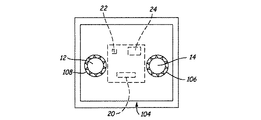
図2Aと図2Bは、図1に示す蓄電池10の上側平面図である。図2Aに示すように、バッテリテストモジュール16には、オプション入力部20とオプション出力部22、24が備わっている。入力部20には、オペレータによる起動やシステムによる自動操作が可能な入力部や押しボタンを採用できる。出力部22には、LEDやその他のバッテリテスト結果である合格/不合格を示す視覚表示素子を利用できる。しかしながら別例として、適当な技術を使用して、データを出力部24から遠隔地のコンピュータやモニタ装置へ送信することも可能である。また、出力部24から、バッテリテストの定量出力値を提供することもできる。図2Bでは、前記出力部22が、一列に配置された出力部23A、23B、23C、23Dで構成されており、この出力部は発光ダイオード(LED)であっても構わない。
2A and 2B are top plan views of the
図3は、図2の破線3に沿った蓄電池10の側断面図である。図3に示すように、蓄電池10は、鉛電池などの蓄電池であり、導線32で直列に電気接続された複数の電気化学セルを備えている。つまり、片端が導線34を介して正端子12に電気接続し、他端が導線36を介して負端子14に電気接続した複数のセル30が列を形成しているのである。図3に示すように、バッテリテストモジュール16は、ケルビン接続38および40である2対の電気接続を経由して端子12と14に結合している。なお、端子12と14への接続は、外部電池電極12または14への直接接合、電池電極12や14に工具形成、モールド形成、または、一体形成された電極延長部を介した接続、電池電極12または14への直接の内部または外部配線接続、あるいは、電池電極12または14と電池ケースの一体構造接続などにより実現することができる。
FIG. 3 is a side sectional view of the
実際の動作においては、ユーザがバッテリテストモジュール16を使って、蓄電池10の状態をテストすることができる。例えばボタン20や別の入力装置を介して起動させれば、蓄電池のテストを実行できるのである。このバッテリテストの結果は、出力部22または24に表示される。別の実施形態として、バッテリテストモジュール16が蓄電池をモニタリングし、この蓄電池が使用されていなかったり、蓄電池が接続される電気システムに過度のノイズが存在していなければ、一時停止した後バッテリテストを実行する。このバッテリテストの結果はメモリに記憶され、出力部22か24で表示される。このような実施形態では、テストの実行に入力部20などの入力器を必要としないが、長い時間に渡って、テストモジュール16に内蔵の回路が蓄電池を放電するおそれがある。
In actual operation, the user can use the
図2Bに示す実施形態では、バッテリテストモジュール16において、端子12と端子14との間の電圧値を、複数の異なるしきい値電圧と比較する。そして、蓄電池10の電圧値に応じて、テストモジュール16上のLED23A〜Dが所定数だけ点灯する。各LEDはそれぞれ異なるしきい値に対応させておくことが可能である。このしきい値については、所望の間隔で設定できる。また、LED23A〜Dは、例えば23Aを赤色LED、23Dを緑色LEDというようにそれぞれ異なる色に設定することも可能である。もう少し複雑な実施形態として、電圧の測定中または測定前に、モジュール16中の負荷抵抗などの負荷が蓄電池10に加えられることができる。この場合のモジュール16の出力値は、印加された負荷の関数となる。
In the embodiment shown in FIG. 2B, the
また別の実施形態では、所定しきい値に到達するまで、テストモジュール16の出力部23A〜Dを連続的に点灯させる。また、より理想的なユーザインターフェースを提供するために、各LEDが点灯する間隔をすこし遅延させることも可能である。点灯タイミングは適当でよい。バッテリテストの結果は、出力部23A〜Dにおいて、ユーザがその結果を確認できるような十分な長さの、所望する時間のあいだ保持することもできる。さらに別の実施形態として、テストが終了するまで所定数のLEDを点灯したままに保持する。また、一度に1つのLEDしか点灯させない実施形態も可能である。つまり、これらLEDやしきい値の数は任意で選択すればよいのである。さらに、記号や警告を示すLEDを点灯させて、オペレータに追加の情報を伝達するような実施形態でもよい。
In another embodiment, the
図2Bの実施形態におけるバッテリテスタの回路は、当業者には自明であるような簡単なコンパレータとタイミング回路とにより実現できる。より複雑な実施形態として、小型マイクロプロセッサの採用も可能である。一般的にバッテリテストモジュール16の回路は、蓄電池10から電力が供給される。
The circuit of the battery tester in the embodiment of FIG. 2B can be realized by a simple comparator and timing circuit as will be apparent to those skilled in the art. As a more complicated embodiment, a small microprocessor can be adopted. In general, the circuit of the
図4には、前記蓄電池10における、バッテリテストモジュール16とセル30との電気接続をより詳細に示す。図中では、セル30を電池の電気記号で表示してある。バッテリテストモジュール16は、ケルビン接続38および40によって電気化学セル30に結合している。
FIG. 4 shows the electrical connection between the
前記バッテリテストモジュール16のマイクロプロセッサーは、後で検索できるように情報をメモリ44に蓄積できる。例えば、電池の使用履歴および充電履歴に関する情報を、後で取り出せるようメモリに保存しておくことができる。このデータを出力部22や24、または、その他の出力部に出力するには、特別なアクセスコードをユーザ入力部に入力すればよい。前記出力が、連続する音色や予め録音された音声などの音響出力であるような実施形態も可能である。また、前記入力部を、特定のボタン列、または、ボタンを押すタイミングで構成することもできる。さらに、この入力部には、IRセンサ、振動センサ、磁気スイッチ、外部装置などに誘導結合する近接レシーバなどを利用することも可能である。前記出力は、外部装置で読み取られるデジタル記号に応じたLEDの点灯により表示できる。他の種類の出力部として、IRリンク、誘導結合などの近接通信技術等によっても実現できる。前記以外の出力技術には、シリアル出力、または、ハードワイヤ出力、RF出力、光学出力がある。さらに、前記いずれかの通信技術を用いて、遠隔コンピュータまたはその他の回路から入力部20や26を経由して受信された入力信号に基きバッテリテストを開始することも可能である。同様の技術を使って、メモリに記憶されている情報のデータ廃棄も実行できる。また、正端子12および負端子14にてデータ変調を行い、テストモジュール16へ出力および入力することもできる。前記データは、バッテリモジュール16内の送受信回路により受信または送信する。前記データ変調技術については、様々なものが当業者において知られている。さらにまた、蓄電池10が接続できる外部回路に干渉しない変調技術を選択できるような実施形態も可能である。
The
前記データの記録/報告技術を使えば、製造者がバッテリの使用状況をモニタすることもできる。例えば、バッテリの故障の原因となるような、バッテリが販売前に長期間にわたって未充電状態で放置されていたかどうかを製造者が判別できる。バッテリ18の寿命中に発生する様々な事象を日付で特定できるよう、日付データがバッテリテストモジュール16のマイクロプロセッサに記憶されている場合、前記メモリに記憶されたデータを日付情報に関連付けすることも可能である。メモリ44に記憶可能なその他の情報には、製造日、バッテリ定格、別のIDであるバッテリ通し番号、販売網などがある。
Using the data recording / reporting technology, the manufacturer can also monitor battery usage. For example, the manufacturer can determine whether or not the battery has been left uncharged for a long time before sale, which may cause a battery failure. If date data is stored in the microprocessor of the
図4は、本発明の別の実施例を示す。つまり、図4の素子10は、内部バッテリ30を備えたスタンバイジャンパ、つまり、補助システム10である。ジャンパケーブルや、その他タバコ点火用アダプターなどの出力部を内部バッテリ30に結合すれば、自動車の補助電源としても使用可能である。このような装置は、たとえば自動車への短時間の充電や、バッテリの故障した別の自動車の始動、つまり「ジャンプスタート」にも使用できる。前記ような装置は、当業者には公知のものであり、内部電池を備えた一般的に小型で持ち運び可能なものである。この内部電池には、ゲルセル、NICAD電池、ニッケル水素電池、または、その他の種類の電池を採用できる。しかしながら、このような補助電源装置の問題点の1つは、ユーザが気付かないうちに内部電池が故障する可能性があることである。つまり、補助電源装置を使用する必要が生じたときに、その電池が壊れてしまっているかもしれないのである。さらにその故障は、正常な電圧値を出力しながら必要な電流がまったく供給できないという、発見しにくいものである可能性がある。しかしながら本発明においては、装置10に、電池30をテストするためのテストモジュール16を装備することもできる。このような実施形態においては、故障していないことを確認するため、ユーザによる定期的な電池30のテストが実行できるのである。さらに、テストモジュール16では、定期的なテストの結果、電池30が故障していた場合には、警告音や点滅ライトにより警告を発する。また、本発明の特徴の1つとして、補助電池装置のテストで使用するバッテリテスタの種類は問わないことである。
FIG. 4 shows another embodiment of the present invention. That is, the
本発明の一つの特徴は、前記バッテリテストモジュールが、図4に示すような時間依存強制関数(time varying forcing function)Fを使って得られる電池の測定値、つまり、電池の動的パラメータに基いて、電池の状態を判定できることである。図4の測定結果の信号は、前記動的パラメータの判定に利用できる。動的パラメータとして、例えば、動的コンダクタンス、レジスタンス、インピーダンス、アドミタンスなどがある。別の例では、電池における測定に単接点を使用することも可能である。 One feature of the present invention is that the battery test module is based on battery measurements obtained using a time varying forcing function F as shown in FIG. In other words, the state of the battery can be determined. The measurement result signal shown in FIG. 4 can be used to determine the dynamic parameter. Examples of the dynamic parameter include dynamic conductance, resistance, impedance, and admittance. In another example, a single contact can be used for measurements in a battery.
メモリ44などテストモジュール16に備わるメモリには、電池10の定格などの電池の固有情報を蓄積できる。これらの情報は、製造過程で永久メモリに取込むことが可能である。そのため、ユーザは電池に関する情報を何も入力する必要がない。前記情報は、バッテリテストの実施、および、電池の質に関する出力値をユーザに提供できる。
The memory provided in the
出力部22には、視覚的出力器などあらゆる種類の出力器具を採用できる。例えば、2色または3色の発光ダイオード(LED)を使用してもよい。このLEDの発光色により、良好、不良、低充電量、(低量過ぎるため)測定不能、または、その他の電池状態および測定結果を示せる。また、LEDの点滅を使って、システムノイズや不良セル、その他の電池状態および測定結果を表示することもできる。ユーザ入力部20の使用中は、起動されないかぎり回路から電池へのドレイン供給は行われない。しかしながら、スイッチなどの入力部を採用した場合、コストの増加と、高システムノイズ発生中などの不適切な時にユーザがテストを実行しかねないという欠点がある。
Any kind of output device such as a visual output device can be adopted for the
入力部20を備えない実施形態では、テストモジュール16を、静止時間、または、テスト実施に適した時間だけ、待機状態にできる。測定結果は、内部メモリに記憶され、定期的に出力部22/24で短時間表示される。しかしながら、テストモジュールを長時間作動させると、蓄電池が消耗する。実施形態の1つとして、蓄電池充電中の電圧上昇時に、スタートアップ回路は、テストモジュールを「起動」させるように、トリガされることができる。この回路は、充電終了後など充電が行われていない間は、節電のため「スリープ」モードに入ることができる。
In an embodiment that does not include the
本発明によるバッテリテストモジュールは、蓄電池と一体形成されることが好ましい。例えば、前記モジュールは、ハウジング、例えばその上カバー部に取り付けることが可能である。その他の実施形態として、前記モジュールをハウジング体に内蔵したり、ハウジング体内の個別の仕切部分に収容したりしても構わない。前記ケルビン接続は、外部または内部の導線を介して前記電池の端子に結合できる。 The battery test module according to the present invention is preferably formed integrally with the storage battery. For example, the module can be attached to a housing, for example an upper cover part thereof. As other embodiments, the module may be built in the housing body or housed in an individual partition portion in the housing body. The Kelvin connection can be coupled to the battery terminals via external or internal leads.
前記テスト回路とテストモジュールは、当然、蓄電池の収納体の変更を必要としない技術を含む、あらゆる技術を用いて前記蓄電池に取付け可能である。例えば、ボルトを使った蓄電池の電極への固定や、電極への圧着つまり「トラップ」構造による固定が利用できる。このように、前記回路は、既存のバッテリに随意に取り付けることが可能なのである。 Naturally, the test circuit and the test module can be attached to the storage battery using any technique including a technique that does not require a change in the storage body of the storage battery. For example, fixing of the storage battery to the electrode using bolts, or crimping to the electrode, that is, fixing by a “trap” structure can be used. Thus, the circuit can be optionally attached to an existing battery.
さらに、本発明の特徴として、冷クランク電流(cold cranking amps;CCA)などの電池の状態に関するデータ出力の提供、および/または、電池への結合のためのケルビン接続の使用が可能な、電池と一体型形成または電池に半永久的に固定されたあらゆるテスタを提供する。 In addition, as a feature of the present invention, a battery capable of providing data output regarding battery status, such as cold cranking amps (CCA), and / or using a Kelvin connection for coupling to the battery, Provide any tester that is monolithic or semi-permanently secured to the battery.
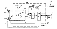
図5は、テストモジュール16の簡略化された回路図である。図中のモジュール16は蓄電池10に接続されており、本発明の実施例にしたがって作動し、蓄電池10のコンダクタンス(GBAT)と、端子12と14との間の電圧電位(VBAT)とを測定する。モジュール16には、電流源50、差動増幅器52、アナログ/デジタル変換器54、および、マイクロプロセッサ56が備わる。増幅器52は、キャパシタC1およびC2を介して蓄電池10に容量接続している。また、増幅器52は、アナログ/デジタル変換器54の入力部に接続する出力部を備える。マイクロプロセッサ56は、システムクロック58、メモリ60、視覚出力部62、アナログ/デジタル変換器54とに接続している。さらに、マイクロプロセッサ56は、入力装置26からの入力信号を受信する機能も備えている。また前記プロセッサには、入力/出力(I/O)ポート67が備わっている。
FIG. 5 is a simplified circuit diagram of the
実際の動作において、電流源50は、マイクロプロセッサ56で制御され、図5の矢印で示した方向に電流を供給する。実施形態では、この電流が方形波またはパルス波形をもつ。差動増幅器52は、蓄電池10の端子22と24にそれぞれキャパシタC1とC2を介して接続しており、端子12と14との間の電圧の電位差に関する出力を行う。増幅器52が高入力インピーダンスをもつような好適実施形態も可能である。回路16には、端子14と12にそれぞれ接続された反転および非反転入力端を有する差動増幅器70が備わる。この増幅器70は、端子12と14との間の蓄電池10の開回路の電位圧(VBAT)を測定するために、接続されている。増幅器70の出力は、マイクロプロセッサ56で端子12と14との間の電圧を測定するために、アナログ/デジタル変換器54へ送られる。
In actual operation, the
モジュール16は、ケルビン接続で知られる4端子接続技術により、蓄電池10に接続されている。このケルビン接続により、電流Iは第1対端子を経由して蓄電池10へ流れ、端子12と14の間の電圧Vが第2対接続端子にて測定される。増幅器52にはわずかな電流しか流れないため、入力部から増幅器52における電圧降下は、バッテリ12の端子12と14との間の電圧降下とほぼ同等である。差動増幅器52の出力信号は、デジタル形式に変換され、マイクロプロセッサ56へ入力される。マイクロプロセッサ56は、システムクロック58で定められた周波数で、メモリ60に記憶されたプログラム指示に従って動作する。
The
マイクロプロセッサ56は、電流源50を使って電流パルスIを流すことにより、蓄電池10のコンダクタンスを決定する。また、該マイクロプロセッサは、増幅器52とアナログ/デジタル変換器54とを使って、電流パルスIによるバッテリ電圧の変化を測定する。電流源50で生成される電流Iの値は公知のものであり、メモリ60に記憶されている。一実施形態として、蓄電池10に負荷をかけることで電流Iを生成することもできる。マイクロプロセッサ56では、下記の式により蓄電池10のコンダクタンスを算出する。
コンダクタンス=GBAT=ΔI/ΔV (式1)
ただし、ΔIは、電流源50により蓄電池10を流れる電流の変動値であり、ΔVは、電流ΔIが流れることによる蓄電池の電圧の変動値である。蓄電池10に温度センサ62を熱接続して、蓄電池における測定を補正することも可能である。この温度測定値は、後で検索できるようメモリ60に記憶しておいても構わない。
The
Conductance = G BAT = ΔI / ΔV (Formula 1)
However, ΔI is a fluctuation value of the current flowing through the
本発明は、テストモジュール16に、蓄電池の充電/放電電流値を測定する電流センサ63を備えるような実施形態も可能である。この蓄電池の電流測定値は、蓄電池10の健全性や充電状態を比較的正確に判定するために、マイクロプロセッサ56で処理される。
In the present invention, an embodiment in which the
図6は、図2Bに示すモジュール16の一実施形態の概略図である。コンパレータ90では、定期的に電圧測定値を複数の参照数値と比較し、それに応じて蓄電池10の状態を表示できるようLED23A〜Dを駆動させる。この表示装置は、スイッチやその他の設定により実現または作動できる。なお、これまで示した図におけるすべての特徴と説明は、別の適切な構造にも適用できるもので、ここに挙げた特定の実施例のみに限定されるものではない。
FIG. 6 is a schematic diagram of one embodiment of the
本発明の特徴の1つは、バッテリテストモジュール16が、自動車の製造過程および/または搬送中でも使用できることである。モジュール16は、自動車製造工程において、蓄電池10に装着可能である。自動車が組立ラインを移動する間には、例えばラジオがオンになる、スタータが駆動する、ヘッドライトが点灯するといったように、多様な負荷が電気システムに加わる。このときバッテリが放電した場合にはモジュール16が表示を出すので、ディーラへ搬入したり顧客に販売する前に、再充電(故障、または、故障しそうな場合は交換)しなくてはならない。モジュール16は、蓄電池10が放電し再充電が必要であることを示す、視覚的出力などの出力を行う。
One feature of the present invention is that the
モジュール16を、特定の蓄電池10の定格に基く情報を記憶するように設定することも可能である。この情報はバッテリテストにおいて、蓄電池の再充電が必要かどうかを判断するのに使用できる。モジュール16は、自動車の組立てや搬入が終わると蓄電池10から取り外しでき、組立ラインの別の車両に接続し直して再使用することができる。
It is also possible to set the
車両の製造過程や運搬中に使用されるモジュールを含む本発明の様々な実施例においても、モジュール16は、単数または複数の彩色LEDにより、簡単な合格/不合格の視覚出力を提供できる。また、IR、RF、外部データバスまたは接続を介して車両のデータバスに接続して、追加データを別の装置へ出力させることも可能である。また、バッテリの温度、使用履歴、サイクル履歴などに関する情報等の追加データを、後で検索できるよう記憶しておける。前記データは、タイムスタンプ処理または日付スタンプ処理をして、車両製造中に発生しがちな共通の故障を診断するのにも使用できる。シリアル番号、複数の蓄電池特性、自己学習機能などの追加情報も、メモリに記憶することができる。
In various embodiments of the present invention, including modules used during vehicle manufacturing and transportation, the
一般的に、モジュール16において実行される測定や算定は、タイムスタンプ処理または日付スタンプ処理することが可能である。このタイムスタンプ処理や日付スタンプ処理された情報に基いて、モジュール16は、車両に装着後の蓄電池の未使用期間、蓄電池の在庫期間、蓄電池が完全に放電状態にあった期間等に関するデータ出力を行う。
In general, the measurements and calculations performed in
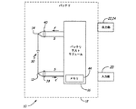
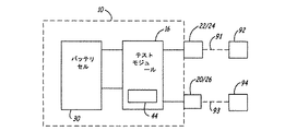
図7は、本発明による蓄電池の別の実施形態を示す。図7に示す複数の部品は、図1〜図6に示したものと同様であるため、同じ参照番号を付けてある。加えて図7には、テストモジュール16がそれぞれ通信リンク91と93を介して通信可能な、遠隔に設置した出力部92および入力部94も示す。テストモジュール16は、出力部22/24、および/または、遠隔出力装置92へ、蓄電池状態の情報を出力できる。前記遠隔出力装置として、ゲージ、メータ、スピーカなどのあらゆる出力装置を採用できる。遠隔出力装置92は、例えば、蓄電池10を装備する車の運転席や、ダッシュボードなどに設置してもよい。前記遠隔出力装置92は、アナログ出力装置やデジタル出力装置であっても構わない。通信リンク91には、ワイヤレス通信リンク、結線通信リンク、光通信リンクなど、あらゆるタイプの通信リンクの使用が可能である。また、通信リンク91は、コントローラエリアネットワーク(CAN)バス、ローカルインターコネクトネットワーク(LIN)バスなど、車両搭載バスであってもよい。テストモジュール16は、通信リンク91および遠隔出力装置92の種類に応じた形式で、テスト状況の情報を遠隔出力部92へ送信できる。つまり、テスト状況の情報は、アナログ形式、デジタル形式、RF信号形式、IR信号、音響信号などで伝送可能なのである。また、テストモジュール16は、通信リンク93を介して、遠隔入力装置94から起動信号を受信することができる。前記通信リンク91と同様に通信リンク93は、遠隔入力部94からテストモジュール16への起動信号を伝送できる通信リンクであれば、どんなものでも構わない。例えば、通信リンク93を介してテストモジュール16に起動信号を発信するような、遠隔地に設置された押しボタン式起動装置で入力部94を構成できる。また、蓄電池10を装備した車両が走行または停止すると、遠隔入力部94が自動的に起動信号を発信するような例でも構わない。この起動信号は、RF信号、IR信号、音響信号、デジタル信号、CANバス信号、LINバス信号などの形式であってもよい。前記遠隔入力部94は、蓄電池10を装備した車の運転席やダッシュボードなどに設置することができる。入力部20/26には、所定時間を過ぎると起動信号を発信するよう設定されたタイミングコントローラを装備してもよい。また、遠隔入力部94にも、所定時間を過ぎると起動信号を発信するよう設定されたタイミングコントローラを装備できる。テストモジュール16は、通信リンク91を介して、蓄電池状態の履歴情報を遠隔出力装置92へ伝送することも可能である。本発明の実施形態では、蓄電池のテスト装置を、テストモジュール16、通信リンク91および93、遠隔出力装置92、遠隔入力装置94で構成しても構わない。
FIG. 7 shows another embodiment of a storage battery according to the present invention. The parts shown in FIG. 7 are the same as those shown in FIG. 1 to FIG. In addition, FIG. 7 also shows remotely installed output unit 92 and
図8は、異なる出力部に伝送された蓄電池状態の情報内容を示すブロック図である。図8に示すように、蓄電池状態の情報96には、ブロック97に表示されるリアルタイムの測定値(バッテリ電流値、電圧値など)と算出結果、および、ブロック98に表示されるメモリ44に記憶された測定値と結果とがある。バッテリテストモジュール16は、蓄電池状態の情報96を、出力部22、24、92など別々の出力部に伝送することもできる。
FIG. 8 is a block diagram showing information contents of storage battery states transmitted to different output units. As shown in FIG. 8, the storage
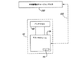
図9は、本発明のさらに別の実施形態である一体型バッテリテストモジュールを備えた蓄電池を示す。なお、図9中の図1〜図7に示すものと同様の部品には、同じ番号を付けてある。図9には、テストモジュール16が通信リンク102を介して通信できる、外部蓄電池チャージャ/テスタ100も示してある。
FIG. 9 shows a storage battery including an integrated battery test module according to still another embodiment of the present invention. In addition, the same number is attached | subjected to the components similar to what is shown in FIGS. 1-7 in FIG. Also shown in FIG. 9 is an external battery charger /
通信リンク102は、通信リンク91と93(図7)で説明したように、あらゆる形式の結線リンクまたはワイヤレスリンクであってもよく、テストモジュール16からの蓄電池状態の情報を、外部の蓄電池チャージャ/テスタ100に伝送する機能をもつ。さらに、通信リンク102を介して、外部の蓄電池チャージャ/テスタ100からのデータをテストモジュール16で受信することもできる。また、蓄電池状態の情報に、蓄電池10の品質保証コードを含むような実施例も可能である。この品質保証コードは、テストモジュール16または外部の蓄電池チャージャ/テスタ100で決定できる。バッテリモジュール16は、さらに、蓄電池状態の履歴情報を、メモリ44から外部の蓄電池チャージャ/テスタ100へ伝送する機能ももつ。前述のように、この履歴情報は、蓄電池の使用状態をモニタし、蓄電池の寿命期間で発生する様々な出来事の記録を保持するのに利用できる。本発明の別の実施形態として、バッテリテストモジュール16に、外部の蓄電池チャージャ/テスタ100の計算アルゴリズムとほぼ同様で、互換性のある1つまたは複数の計算アルゴリズムを実行させることも可能である。さらに別の実施例として、前記互換性計算アルゴリズムで、蓄電池100の健全性や充電状態を判断することもできる。このような計算アルゴリズムの互換性により、テストモジュール16と外部の蓄電池チャージャ/テスタ100との間での、中間計算や計算結果の交換が可能となる。これらの交換された中間値や計算結果は、テストモジュール16と外部の蓄電池チャージャ/テスタ100で追加の計算を行うために使用されることができる。
The
前述した本発明の実施形態では、前記テストモジュールについて、例えば蓄電池の電極にボルトで脱着可能に取り付けられた、または、バッテリに半永久的に固定された装置であると説明してきた。これらの実施形態におけるバッテリテストモジュールは、通常、電子部品が搭載された固体プリント基板(PCB)を備えているため、そのサイズは比較的大きい。一般的に、前記ようなバッテリテストモジュールにバッテリハウジング体を一体化させるには、バッテリケースやハウジング体の変更が必要がある。さらに、蓄電池は外部寸法に基いてサイズ分類されているため、比較的大きいバッテリテストモジュールを取付けると、その蓄電池のサイズ分類が変ってしまうことがある。そのため、前記バッテリテストモジュールは、蓄電池と別個の部品である従来のものよりも優れた点があるにも関わらず、その製造および搭載にかかるコストが高くなってしまう。そこで、バッテリケースの変更が不用で、蓄電池サイズ分類に影響せず、どのようなサイズ分類の蓄電池にも取り付け可能な本発明の実施形態について、図10を用いて説明する。 In the above-described embodiment of the present invention, the test module has been described as an apparatus that is detachably attached to an electrode of a storage battery, for example, or is semi-permanently fixed to a battery. Since the battery test modules in these embodiments usually include a solid printed circuit board (PCB) on which electronic components are mounted, the size thereof is relatively large. Generally, in order to integrate the battery housing body into the battery test module as described above, it is necessary to change the battery case and the housing body. Furthermore, since the storage batteries are sized according to external dimensions, the size classification of the storage battery may change if a relatively large battery test module is installed. Therefore, although the said battery test module has the point superior to the conventional thing which is a separate component from a storage battery, the cost concerning the manufacture and mounting will become high. Therefore, an embodiment of the present invention that can be attached to a storage battery of any size classification without changing the battery case and not affecting the storage battery size classification will be described with reference to FIG.
図10は、バッテリテストモジュール104を装着した蓄電池10の側面図である。この実施形態におけるバッテリテストモジュール104の構成部品は、前記バッテリテストモジュール16のものと同様の機能をもつ。しかしながら、バッテリテストモジュール104は、フレキシブル回路技術および/またはフリップチップ技術により形成され、埋込み電子部品を備えた柔軟性のある「バッテリラベル」形式である。そのため、バッテリテストモジュール104は、ワンサイズで製造でき、どんな分類サイズの蓄電池のハウジング体の壁面にも装着可能である。さらに、このモジュール104は比較的薄いラベル形状であるため、モジュールを装着するバッテリの寸法つまり分類サイズの変更は必要ない。前述した利点により、バッテリテストモジュール104は、比較的低コストで大量生産が可能なのである。バッテリテストモジュール104を蓄電池10に機械的および電気的に接続する技術については、図11に関連して以下に説明する。
FIG. 10 is a side view of the
図11は、図10の蓄電池10の上側平面図である。図から分るように、バッテリテストモジュール104は、テストモジュール16(図2A)のものと同様の部品から構成されているが、テストモジュール104は複数の前記柔軟層から形成されている。このバッテリテストモジュール104は、番号106と108で示す「トラップ」構造により、蓄電池電極12および14に嵌合されている。電極つまり端子の把持部106と108は、バッテリテストモジュール104中の溝からなり、電極12と14に電気接続できるように、その溝に出っ張る導電歯部が設けられている。バッテリテストモジュール104の把持部は、異なる蓄電池サイズの電極に接続できるよう弾力性をもたせても構わない。また、このテストモジュール104の底面を、適当な接着剤で蓄電池10の表面に接着することもできる。別の実施形態として、バッテリテストモジュール104の第1部分を蓄電池のハウジング体の表面に接着し、その残りの部分を湾曲させて前記ハウジング体の側面に接着することも可能である。さらに、バッテリテストモジュール104が、バッテリハウジング体の外面(上面と側面)上の凸凹と整合できるよう薄く柔軟性をもつような実施形態でも構わない。本発明のさらに別の実施形態として、バッテリテストモジュール104を蓄電池10のハウジング体に半永久的に接着することもできる。またさらに、バッテリテストモジュール104を、蓄電池10のハウジング体に一時的に固定したり、または、随意に脱着可能とする実施形態も可能である。
FIG. 11 is an upper plan view of the
図12は、テストモジュール104の実施形態の部分断面図である。図から分るように、テストモジュール104は、熱拡散層110、接着層112、フレキシブル基板114、フレキシブル回路116、保護層118からなる多層構造をもつ。バッテリテストを実行するためにテストモジュール104を起動させる押しボタン20などの部品は、フレキシブル回路116の表面に載置され、演算増幅器52および70とマイクロプロセッサ56などの部品はフレキシブル回路の底面に設置されており、フレキシブル基板114と封止材124にて支持されている。増幅器52と70、マイクロプロセッサ56のような部品を封止することで、テストモジュール104の強度が向上し、部品にかかるストレスが軽減される。増幅器52、70、およびマイクロプロセッサ56などの部品は、フリップチップ技術、表面搭載技術、その他当業者に公知の工業技術、または将来開発される技術により、フレキシブル回路116に搭載しても構わない。前記部品の搭載にフリップチップ技術を採用する例は、米国特許第6,410,415号、『フリップチップ搭載技術』で解説してある。
FIG. 12 is a partial cross-sectional view of an embodiment of the
フレキシブル回路116は多層構造であって、前述のようにその上にはレジスタや(20のような)押しボタンのような部品が加減形成法によって形成され、(増幅器52、70、およびマイクロプロセッサ56などの)他の部品が搭載されている。フレキシブル回路の形成法の一例は、米国特許第6,150,071号、『フレックス回路アプリケーションの製造工程』に説明されている。
The
図12に関連したテストモジュール104の実施形態は、本発明の一実施例にすぎない。本発明の本質や範囲から逸脱することなく、これらの層の数や種類の変更や、(20、52、56、70などの)部品の異なる層への配置、および、各層の形成には別の適当な素材(混合材でもよい)を使用することも可能である。
The embodiment of
本発明について、好適な実施形態を参照しながら説明してきたが、本発明の本質と範囲から逸脱することなく、その形式と細部への変更が可能であることは当業者にとって明白であろう。なお、蓄電池10については、複数の電気化学セルを備えた形態で説明してきたが、単体の電気化学セルからなる蓄電池10を採用する実施形態も可能であることを付け加えておく。
Although the present invention has been described with reference to preferred embodiments, it will be apparent to those skilled in the art that changes can be made in form and detail without departing from the spirit and scope of the invention. In addition, although the
10……蓄電池、12……正(+)端子、14……負(−)端子、16……バッテリテストモジュール、18……ハウジング体、20……オプション入力部、22,24……オプション出力部、23A,23B,23C,23D……一列に配置された出力部、30……セル、32,34,36……導線、38,40……ケルビン接続 10 ... Storage battery, 12 ... Positive (+) terminal, 14 ... Negative (-) terminal, 16 ... Battery test module, 18 ... Housing body, 20 ... Option input section, 22, 24 ... Option output , 23A, 23B, 23C, 23D ... Outputs arranged in a row, 30 ... Cell, 32, 34, 36 ... Conductor, 38, 40 ... Kelvin connection
Claims (17)
蓄電池ハウジング体と、
前記蓄電池の正端子と負端子に直列に電気的に接続された、前記蓄電池ハウジング体内の少なくとも1個の電気化学セルと、
前記蓄電池の正端子に結合された第1ケルビン接続部と、
前記蓄電池の負端子に結合された第2ケルビン接続部と、
前記第1と第2のケルビン接続部をそれぞれ経由して前記正端子と負端子に電気的に接続され、前記蓄電池ハウジング体に固定され、かつ埋め込まれた電子部品を有する可撓性多層構造である蓄電池テストモジュールと、
蓄電池状態情報を出力できるよう形成された前記蓄電池テストモジュールからの出力部とからなる蓄電池。 A storage battery,
A storage battery housing body;
At least one electrochemical cell in the storage battery housing electrically connected in series with the positive and negative terminals of the storage battery;
A first Kelvin connection coupled to the positive terminal of the storage battery;
A second Kelvin connection coupled to the negative terminal of the storage battery;
A flexible multi-layer structure having electronic components electrically connected to the positive and negative terminals via the first and second Kelvin connections, respectively, fixed to the storage battery housing body and embedded; A storage battery test module,
A storage battery comprising: an output unit from the storage battery test module formed to output storage battery state information.
前記蓄電池の正端子に接続された第1ケルビン接続部と、
前記蓄電池の負端子に接続された第2ケルビン接続部と、
前記第1と第2のケルビン接続部をそれぞれ経由して前記正端子と負端子に電気的に接続され、蓄電池の蓄電池ハウジング体に固定され、かつ埋め込まれた電子部品を有する可撓性多層構造である蓄電池テストモジュールと、
蓄電池状態情報を出力できるよう形成された前記蓄電池テストモジュールからの出力部とからなる蓄電池テスト装置。 A storage battery testing device,
A first Kelvin connection connected to the positive terminal of the storage battery;
A second Kelvin connection connected to the negative terminal of the storage battery;
A flexible multilayer structure having electronic components that are electrically connected to the positive and negative terminals via the first and second Kelvin connections, respectively, fixed to the storage battery housing body of the storage battery and embedded A storage battery test module,
A storage battery test device comprising: an output unit from the storage battery test module formed to output storage battery state information.
補助蓄電池と、
前記補助蓄電池に電気接続され、前記補助蓄電池の電池テストを行なって電池テスト値を出力できるよう形成され、かつ前記補助蓄電池に固定され、埋め込まれた電子部品を有する可撓性多層構造である電池テストモジュールと、
前記電池テスト結果を出力できるよう形成された出力部とからなる補助電力装置。 An auxiliary power device,
An auxiliary storage battery,
A battery having a flexible multilayer structure that is electrically connected to the auxiliary storage battery, is formed so that a battery test value of the auxiliary storage battery can be output and a battery test value is output, and is fixed to the auxiliary storage battery and has an embedded electronic component A test module;
An auxiliary power device including an output unit configured to output the battery test result.
Applications Claiming Priority (2)
| Application Number | Priority Date | Filing Date | Title |
|---|---|---|---|
| US10/310385 | 2002-12-05 | ||
| US10/310,385 US6795782B2 (en) | 1999-04-08 | 2002-12-05 | Battery test module |
Publications (2)
| Publication Number | Publication Date |
|---|---|
| JP2004200159A true JP2004200159A (en) | 2004-07-15 |
| JP4916087B2 JP4916087B2 (en) | 2012-04-11 |
Family
ID=32770126
Family Applications (1)
| Application Number | Title | Priority Date | Filing Date |
|---|---|---|---|
| JP2003404695A Expired - Fee Related JP4916087B2 (en) | 2002-12-05 | 2003-12-03 | Storage battery with integrated battery tester |
Country Status (1)
| Country | Link |
|---|---|
| JP (1) | JP4916087B2 (en) |
Cited By (4)
| Publication number | Priority date | Publication date | Assignee | Title |
|---|---|---|---|---|
| JP2014038862A (en) * | 2013-10-17 | 2014-02-27 | Mitsubishi Motors Corp | Inspection system of battery pack |
| JP2017503177A (en) * | 2013-10-02 | 2017-01-26 | エルジー・ケム・リミテッド | Battery cell assembly |
| JP2019212453A (en) * | 2018-06-02 | 2019-12-12 | 株式会社Kkbテクノロジー | Lead storage battery |
| CN112339608A (en) * | 2019-08-09 | 2021-02-09 | 广州汽车集团股份有限公司 | Battery thermal runaway monitoring method, device and system based on smoke concentration and vehicle |
Citations (13)
| Publication number | Priority date | Publication date | Assignee | Title |
|---|---|---|---|---|
| JPS59117290A (en) * | 1982-12-24 | 1984-07-06 | 松下電器産業株式会社 | Flexible copper-lined printed printed board |
| JPS62140760A (en) * | 1985-12-16 | 1987-06-24 | Akio Kato | Barrel polishing device |
| JPH0449474A (en) * | 1990-06-19 | 1992-02-18 | Daikin Ind Ltd | Method and device for generating thick line |
| JPH05251596A (en) * | 1992-03-06 | 1993-09-28 | Sony Corp | Ic chip package structure of flip chip system |
| JPH08106940A (en) * | 1994-09-30 | 1996-04-23 | K Ii C Kk | Lead wire connecting metal fixture and anode connecting structure of flyback transformer |
| JPH09147935A (en) * | 1995-11-22 | 1997-06-06 | Sumitomo Wiring Syst Ltd | Earth terminal mounting structure |
| JP2000082868A (en) * | 1998-09-07 | 2000-03-21 | Sony Corp | Flexible printed wiring board, flexible printed circuit board, and their manufacture |
| JP2000149998A (en) * | 1998-11-02 | 2000-05-30 | Agilent Technol Inc | Battery control system and manufacture of intelligent battery pack |
| WO2001059443A1 (en) * | 2000-02-11 | 2001-08-16 | Midtronics, Inc. | Storage battery with integral battery tester |
| JP2002043500A (en) * | 2000-05-17 | 2002-02-08 | Ngk Spark Plug Co Ltd | Wiring board |
| JP2002198394A (en) * | 2000-11-28 | 2002-07-12 | Polymer Flip Chip Corp | Method for mounting flip-chip on substrate |
| JP2002261421A (en) * | 2001-03-06 | 2002-09-13 | Matsushita Electric Ind Co Ltd | Method of manufacturing component mounted with electronic component, method of manufacturing finished product mounted with electronic component and finished product mounted with semiconductor component |
| JP2002280613A (en) * | 2001-03-19 | 2002-09-27 | Matsushita Electric Ind Co Ltd | Method and member for manufacturing illuminating device |
-
2003
- 2003-12-03 JP JP2003404695A patent/JP4916087B2/en not_active Expired - Fee Related
Patent Citations (13)
| Publication number | Priority date | Publication date | Assignee | Title |
|---|---|---|---|---|
| JPS59117290A (en) * | 1982-12-24 | 1984-07-06 | 松下電器産業株式会社 | Flexible copper-lined printed printed board |
| JPS62140760A (en) * | 1985-12-16 | 1987-06-24 | Akio Kato | Barrel polishing device |
| JPH0449474A (en) * | 1990-06-19 | 1992-02-18 | Daikin Ind Ltd | Method and device for generating thick line |
| JPH05251596A (en) * | 1992-03-06 | 1993-09-28 | Sony Corp | Ic chip package structure of flip chip system |
| JPH08106940A (en) * | 1994-09-30 | 1996-04-23 | K Ii C Kk | Lead wire connecting metal fixture and anode connecting structure of flyback transformer |
| JPH09147935A (en) * | 1995-11-22 | 1997-06-06 | Sumitomo Wiring Syst Ltd | Earth terminal mounting structure |
| JP2000082868A (en) * | 1998-09-07 | 2000-03-21 | Sony Corp | Flexible printed wiring board, flexible printed circuit board, and their manufacture |
| JP2000149998A (en) * | 1998-11-02 | 2000-05-30 | Agilent Technol Inc | Battery control system and manufacture of intelligent battery pack |
| WO2001059443A1 (en) * | 2000-02-11 | 2001-08-16 | Midtronics, Inc. | Storage battery with integral battery tester |
| JP2002043500A (en) * | 2000-05-17 | 2002-02-08 | Ngk Spark Plug Co Ltd | Wiring board |
| JP2002198394A (en) * | 2000-11-28 | 2002-07-12 | Polymer Flip Chip Corp | Method for mounting flip-chip on substrate |
| JP2002261421A (en) * | 2001-03-06 | 2002-09-13 | Matsushita Electric Ind Co Ltd | Method of manufacturing component mounted with electronic component, method of manufacturing finished product mounted with electronic component and finished product mounted with semiconductor component |
| JP2002280613A (en) * | 2001-03-19 | 2002-09-27 | Matsushita Electric Ind Co Ltd | Method and member for manufacturing illuminating device |
Cited By (5)
| Publication number | Priority date | Publication date | Assignee | Title |
|---|---|---|---|---|
| JP2017503177A (en) * | 2013-10-02 | 2017-01-26 | エルジー・ケム・リミテッド | Battery cell assembly |
| KR101833439B1 (en) * | 2013-10-02 | 2018-02-28 | 주식회사 엘지화학 | Battery cell assembly |
| JP2014038862A (en) * | 2013-10-17 | 2014-02-27 | Mitsubishi Motors Corp | Inspection system of battery pack |
| JP2019212453A (en) * | 2018-06-02 | 2019-12-12 | 株式会社Kkbテクノロジー | Lead storage battery |
| CN112339608A (en) * | 2019-08-09 | 2021-02-09 | 广州汽车集团股份有限公司 | Battery thermal runaway monitoring method, device and system based on smoke concentration and vehicle |
Also Published As
| Publication number | Publication date |
|---|---|
| JP4916087B2 (en) | 2012-04-11 |
Similar Documents
| Publication | Publication Date | Title |
|---|---|---|
| US7039533B2 (en) | Battery test module | |
| US6795782B2 (en) | Battery test module | |
| JP2004077480A (en) | Battery test module | |
| US7505856B2 (en) | Battery test module | |
| US7977914B2 (en) | Battery maintenance tool with probe light | |
| US20020010558A1 (en) | Storage battery with integral battery tester | |
| US7446536B2 (en) | Scan tool for electronic battery tester | |
| US7598744B2 (en) | Scan tool for electronic battery tester | |
| WO2001059443A9 (en) | Storage battery with integral battery tester | |
| US7319304B2 (en) | Shunt connection to a PCB of an energy management system employed in an automotive vehicle | |
| US7705602B2 (en) | Automotive vehicle electrical system diagnostic device | |
| US7598699B2 (en) | Replaceable clamp for electronic battery tester | |
| US6888468B2 (en) | Apparatus and method for protecting a battery from overdischarge | |
| US6933727B2 (en) | Electronic battery tester cable | |
| US7808375B2 (en) | Battery run down indicator | |
| US20130127611A1 (en) | Battery marvel 1.0 | |
| US20050212521A1 (en) | Electronic battery tester or charger with databus connection | |
| US20070001680A1 (en) | Condition detection and indicating means for a storage battery | |
| US20020065619A1 (en) | Battery test module | |
| US20050077904A1 (en) | Electronic battery tester with probe light | |
| WO2007027702A2 (en) | Automotive vehicle electrical system diagnostic device | |
| JP5141089B2 (en) | Reader | |
| JP2003264009A (en) | Battery test module | |
| JP5050489B2 (en) | Battery state detection device and lead battery | |
| JP4916087B2 (en) | Storage battery with integrated battery tester |
Legal Events
| Date | Code | Title | Description |
|---|---|---|---|
| A621 | Written request for application examination |
Free format text: JAPANESE INTERMEDIATE CODE: A621 Effective date: 20061023 |
|
| A131 | Notification of reasons for refusal |
Free format text: JAPANESE INTERMEDIATE CODE: A131 Effective date: 20100811 |
|
| A521 | Written amendment |
Free format text: JAPANESE INTERMEDIATE CODE: A523 Effective date: 20101105 |
|
| A131 | Notification of reasons for refusal |
Free format text: JAPANESE INTERMEDIATE CODE: A131 Effective date: 20110831 |
|
| A521 | Written amendment |
Free format text: JAPANESE INTERMEDIATE CODE: A523 Effective date: 20111122 |
|
| TRDD | Decision of grant or rejection written | ||
| A01 | Written decision to grant a patent or to grant a registration (utility model) |
Free format text: JAPANESE INTERMEDIATE CODE: A01 Effective date: 20120111 |
|
| A01 | Written decision to grant a patent or to grant a registration (utility model) |
Free format text: JAPANESE INTERMEDIATE CODE: A01 |
|
| A61 | First payment of annual fees (during grant procedure) |
Free format text: JAPANESE INTERMEDIATE CODE: A61 Effective date: 20120124 |
|
| FPAY | Renewal fee payment (event date is renewal date of database) |
Free format text: PAYMENT UNTIL: 20150203 Year of fee payment: 3 |
|
| R150 | Certificate of patent or registration of utility model |
Ref document number: 4916087 Country of ref document: JP Free format text: JAPANESE INTERMEDIATE CODE: R150 Free format text: JAPANESE INTERMEDIATE CODE: R150 |
|
| R250 | Receipt of annual fees |
Free format text: JAPANESE INTERMEDIATE CODE: R250 |
|
| R250 | Receipt of annual fees |
Free format text: JAPANESE INTERMEDIATE CODE: R250 |
|
| R250 | Receipt of annual fees |
Free format text: JAPANESE INTERMEDIATE CODE: R250 |
|
| R250 | Receipt of annual fees |
Free format text: JAPANESE INTERMEDIATE CODE: R250 |
|
| LAPS | Cancellation because of no payment of annual fees |