JP2004194352A - Image decoding apparatus and image decoding method - Google Patents
Image decoding apparatus and image decoding method Download PDFInfo
- Publication number
- JP2004194352A JP2004194352A JP2004045105A JP2004045105A JP2004194352A JP 2004194352 A JP2004194352 A JP 2004194352A JP 2004045105 A JP2004045105 A JP 2004045105A JP 2004045105 A JP2004045105 A JP 2004045105A JP 2004194352 A JP2004194352 A JP 2004194352A
- Authority
- JP
- Japan
- Prior art keywords
- vop
- information
- unit
- time
- header
- Prior art date
- Legal status (The legal status is an assumption and is not a legal conclusion. Google has not performed a legal analysis and makes no representation as to the accuracy of the status listed.)
- Pending
Links
Images


Classifications
-
- H—ELECTRICITY
- H04—ELECTRIC COMMUNICATION TECHNIQUE
- H04N—PICTORIAL COMMUNICATION, e.g. TELEVISION
- H04N19/00—Methods or arrangements for coding, decoding, compressing or decompressing digital video signals
- H04N19/50—Methods or arrangements for coding, decoding, compressing or decompressing digital video signals using predictive coding
- H04N19/587—Methods or arrangements for coding, decoding, compressing or decompressing digital video signals using predictive coding involving temporal sub-sampling or interpolation, e.g. decimation or subsequent interpolation of pictures in a video sequence
-
- H—ELECTRICITY
- H04—ELECTRIC COMMUNICATION TECHNIQUE
- H04N—PICTORIAL COMMUNICATION, e.g. TELEVISION
- H04N19/00—Methods or arrangements for coding, decoding, compressing or decompressing digital video signals
- H04N19/10—Methods or arrangements for coding, decoding, compressing or decompressing digital video signals using adaptive coding
- H04N19/102—Methods or arrangements for coding, decoding, compressing or decompressing digital video signals using adaptive coding characterised by the element, parameter or selection affected or controlled by the adaptive coding
- H04N19/132—Sampling, masking or truncation of coding units, e.g. adaptive resampling, frame skipping, frame interpolation or high-frequency transform coefficient masking
-
- H—ELECTRICITY
- H04—ELECTRIC COMMUNICATION TECHNIQUE
- H04N—PICTORIAL COMMUNICATION, e.g. TELEVISION
- H04N19/00—Methods or arrangements for coding, decoding, compressing or decompressing digital video signals
- H04N19/20—Methods or arrangements for coding, decoding, compressing or decompressing digital video signals using video object coding
-
- H—ELECTRICITY
- H04—ELECTRIC COMMUNICATION TECHNIQUE
- H04N—PICTORIAL COMMUNICATION, e.g. TELEVISION
- H04N19/00—Methods or arrangements for coding, decoding, compressing or decompressing digital video signals
- H04N19/46—Embedding additional information in the video signal during the compression process
- H04N19/463—Embedding additional information in the video signal during the compression process by compressing encoding parameters before transmission
-
- H—ELECTRICITY
- H04—ELECTRIC COMMUNICATION TECHNIQUE
- H04N—PICTORIAL COMMUNICATION, e.g. TELEVISION
- H04N19/00—Methods or arrangements for coding, decoding, compressing or decompressing digital video signals
- H04N19/60—Methods or arrangements for coding, decoding, compressing or decompressing digital video signals using transform coding
- H04N19/61—Methods or arrangements for coding, decoding, compressing or decompressing digital video signals using transform coding in combination with predictive coding
-
- H—ELECTRICITY
- H04—ELECTRIC COMMUNICATION TECHNIQUE
- H04N—PICTORIAL COMMUNICATION, e.g. TELEVISION
- H04N19/00—Methods or arrangements for coding, decoding, compressing or decompressing digital video signals
- H04N19/70—Methods or arrangements for coding, decoding, compressing or decompressing digital video signals characterised by syntax aspects related to video coding, e.g. related to compression standards
-
- H—ELECTRICITY
- H04—ELECTRIC COMMUNICATION TECHNIQUE
- H04N—PICTORIAL COMMUNICATION, e.g. TELEVISION
- H04N21/00—Selective content distribution, e.g. interactive television or video on demand [VOD]
- H04N21/20—Servers specifically adapted for the distribution of content, e.g. VOD servers; Operations thereof
- H04N21/23—Processing of content or additional data; Elementary server operations; Server middleware
- H04N21/234—Processing of video elementary streams, e.g. splicing of video streams, manipulating MPEG-4 scene graphs
- H04N21/23412—Processing of video elementary streams, e.g. splicing of video streams, manipulating MPEG-4 scene graphs for generating or manipulating the scene composition of objects, e.g. MPEG-4 objects
-
- H—ELECTRICITY
- H04—ELECTRIC COMMUNICATION TECHNIQUE
- H04N—PICTORIAL COMMUNICATION, e.g. TELEVISION
- H04N21/00—Selective content distribution, e.g. interactive television or video on demand [VOD]
- H04N21/20—Servers specifically adapted for the distribution of content, e.g. VOD servers; Operations thereof
- H04N21/23—Processing of content or additional data; Elementary server operations; Server middleware
- H04N21/234—Processing of video elementary streams, e.g. splicing of video streams, manipulating MPEG-4 scene graphs
- H04N21/2343—Processing of video elementary streams, e.g. splicing of video streams, manipulating MPEG-4 scene graphs involving reformatting operations of video signals for distribution or compliance with end-user requests or end-user device requirements
- H04N21/234318—Processing of video elementary streams, e.g. splicing of video streams, manipulating MPEG-4 scene graphs involving reformatting operations of video signals for distribution or compliance with end-user requests or end-user device requirements by decomposing into objects, e.g. MPEG-4 objects
-
- H—ELECTRICITY
- H04—ELECTRIC COMMUNICATION TECHNIQUE
- H04N—PICTORIAL COMMUNICATION, e.g. TELEVISION
- H04N21/00—Selective content distribution, e.g. interactive television or video on demand [VOD]
- H04N21/20—Servers specifically adapted for the distribution of content, e.g. VOD servers; Operations thereof
- H04N21/23—Processing of content or additional data; Elementary server operations; Server middleware
- H04N21/236—Assembling of a multiplex stream, e.g. transport stream, by combining a video stream with other content or additional data, e.g. inserting a URL [Uniform Resource Locator] into a video stream, multiplexing software data into a video stream; Remultiplexing of multiplex streams; Insertion of stuffing bits into the multiplex stream, e.g. to obtain a constant bit-rate; Assembling of a packetised elementary stream
- H04N21/23614—Multiplexing of additional data and video streams
-
- H—ELECTRICITY
- H04—ELECTRIC COMMUNICATION TECHNIQUE
- H04N—PICTORIAL COMMUNICATION, e.g. TELEVISION
- H04N21/00—Selective content distribution, e.g. interactive television or video on demand [VOD]
- H04N21/40—Client devices specifically adapted for the reception of or interaction with content, e.g. set-top-box [STB]; Operations thereof
- H04N21/43—Processing of content or additional data, e.g. demultiplexing additional data from a digital video stream; Elementary client operations, e.g. monitoring of home network or synchronising decoder's clock; Client middleware
- H04N21/4302—Content synchronisation processes, e.g. decoder synchronisation
- H04N21/4307—Synchronising the rendering of multiple content streams or additional data on devices, e.g. synchronisation of audio on a mobile phone with the video output on the TV screen
- H04N21/43072—Synchronising the rendering of multiple content streams or additional data on devices, e.g. synchronisation of audio on a mobile phone with the video output on the TV screen of multiple content streams on the same device
-
- H—ELECTRICITY
- H04—ELECTRIC COMMUNICATION TECHNIQUE
- H04N—PICTORIAL COMMUNICATION, e.g. TELEVISION
- H04N21/00—Selective content distribution, e.g. interactive television or video on demand [VOD]
- H04N21/40—Client devices specifically adapted for the reception of or interaction with content, e.g. set-top-box [STB]; Operations thereof
- H04N21/43—Processing of content or additional data, e.g. demultiplexing additional data from a digital video stream; Elementary client operations, e.g. monitoring of home network or synchronising decoder's clock; Client middleware
- H04N21/434—Disassembling of a multiplex stream, e.g. demultiplexing audio and video streams, extraction of additional data from a video stream; Remultiplexing of multiplex streams; Extraction or processing of SI; Disassembling of packetised elementary stream
- H04N21/4348—Demultiplexing of additional data and video streams
-
- H—ELECTRICITY
- H04—ELECTRIC COMMUNICATION TECHNIQUE
- H04N—PICTORIAL COMMUNICATION, e.g. TELEVISION
- H04N21/00—Selective content distribution, e.g. interactive television or video on demand [VOD]
- H04N21/40—Client devices specifically adapted for the reception of or interaction with content, e.g. set-top-box [STB]; Operations thereof
- H04N21/43—Processing of content or additional data, e.g. demultiplexing additional data from a digital video stream; Elementary client operations, e.g. monitoring of home network or synchronising decoder's clock; Client middleware
- H04N21/44—Processing of video elementary streams, e.g. splicing a video clip retrieved from local storage with an incoming video stream, rendering scenes according to MPEG-4 scene graphs
- H04N21/44012—Processing of video elementary streams, e.g. splicing a video clip retrieved from local storage with an incoming video stream, rendering scenes according to MPEG-4 scene graphs involving rendering scenes according to scene graphs, e.g. MPEG-4 scene graphs
-
- H—ELECTRICITY
- H04—ELECTRIC COMMUNICATION TECHNIQUE
- H04N—PICTORIAL COMMUNICATION, e.g. TELEVISION
- H04N21/00—Selective content distribution, e.g. interactive television or video on demand [VOD]
- H04N21/60—Network structure or processes for video distribution between server and client or between remote clients; Control signalling between clients, server and network components; Transmission of management data between server and client, e.g. sending from server to client commands for recording incoming content stream; Communication details between server and client
- H04N21/65—Transmission of management data between client and server
- H04N21/654—Transmission by server directed to the client
- H04N21/6547—Transmission by server directed to the client comprising parameters, e.g. for client setup
-
- H—ELECTRICITY
- H04—ELECTRIC COMMUNICATION TECHNIQUE
- H04N—PICTORIAL COMMUNICATION, e.g. TELEVISION
- H04N21/00—Selective content distribution, e.g. interactive television or video on demand [VOD]
- H04N21/80—Generation or processing of content or additional data by content creator independently of the distribution process; Content per se
- H04N21/85—Assembly of content; Generation of multimedia applications
- H04N21/854—Content authoring
- H04N21/8547—Content authoring involving timestamps for synchronizing content
-
- H—ELECTRICITY
- H04—ELECTRIC COMMUNICATION TECHNIQUE
- H04N—PICTORIAL COMMUNICATION, e.g. TELEVISION
- H04N7/00—Television systems
- H04N7/24—Systems for the transmission of television signals using pulse code modulation
- H04N7/52—Systems for transmission of a pulse code modulated video signal with one or more other pulse code modulated signals, e.g. an audio signal or a synchronizing signal
Abstract
Description
この発明は、画像処理を行う画像復号化装置および画像復号化方法に関するものである。 The present invention relates to an image decoding device and an image decoding method for performing image processing.
従来のデコード側においては、VOPヘッダ情報を解析する以前に、解析が不必要なVOP(画信号のコマ落しの場合、コマ落しされる情報)と解析が必要なVOP(画信号のコマ落しの場合、コマ落しされない情報)との区別がつかないものであった。 On the conventional decoding side, before analyzing the VOP header information, a VOP that does not need to be analyzed (information that is dropped in the case of frame dropping of the image signal) and a VOP that needs analysis (frame dropping of the image signal). In this case, the information cannot be distinguished from information that is not dropped.
従来の装置は上記のように構成されているため、各VOPヘッダに含まれるVOPスタートコードとモジュロ・タイム・ベースとVOPタイムインクリメントとを必ず解析しなければならないため、処理が面倒で処理精度の低下を招く恐れがあるという課題があった。 Since the conventional device is configured as described above, the VOP start code, the modulo time base, and the VOP time increment included in each VOP header must be analyzed without fail. There was a problem that it could lead to a decrease.
また、画像を構成する被写体、背景、ロゴ等のオブジェクトを単位とし、符号化された信号を復号化及び合成する場合、それぞれのオブジェクトには、復号、合成する際に必要な合成タイミング信号(絶対時刻を表現する情報)が付加されなければならない。画像復号化装置は、絶対時刻を表現する情報を得なければ、各オブジェクトの合成を行えないので、画像再生成が不可能である。要するに、この絶対時間を示す情報を持たないオブジェクトを含む複数オブジェクトから1つの画像を作成しようとする場合、絶対時間を示す情報を持たないオブジェクトとのコンポジションが不可能となる課題があった。
さらに、モジュロ・タイム・ベースのビット長は、次のGOVヘッダが多重化されるまで増加するもので、オプションであるGOVヘッダが多重化されていないと、モジュロ・タイム・ベースのビット長が増加し続けるという課題があった。
In addition, when decoding and synthesizing an encoded signal in units of objects such as a subject, a background, and a logo constituting an image, each object is provided with a synthesizing timing signal (absolute Information representing time) must be added. Unless the image decoding apparatus obtains information representing the absolute time, it is not possible to synthesize the objects, and thus it is impossible to reproduce the image. In short, when one image is to be created from a plurality of objects including an object having no information indicating the absolute time, there has been a problem that the composition with an object having no information indicating the absolute time becomes impossible.
Furthermore, the bit length of the modulo time base increases until the next GOV header is multiplexed, and if the optional GOV header is not multiplexed, the bit length of the modulo time base increases. There was a problem of continuing to do so.
この発明は上記のような課題を解決するためになされたもので、簡単な処理で処理精度が向上する、不必要な情報量の発生を防止する画像復号化装置および画像復号化方法を提供することを目的とする。 SUMMARY OF THE INVENTION The present invention has been made to solve the above problems, and provides an image decoding apparatus and an image decoding method capable of improving the processing accuracy with simple processing and preventing the generation of unnecessary information amount. The purpose is to:
この発明に係る画像復号化装置は、複数のVOPからなるVOPレイヤより上位であるレイヤのヘッダ情報部分に符号化されて含まれ、単位時間あたりに表示するVOPの数が固定レートであるか可変レートかを表すVOPレート情報を復号するVOPレート情報復号手段を備えたものである。 According to the image decoding apparatus of the present invention, the number of VOPs coded and included in a header information portion of a layer higher than a VOP layer including a plurality of VOPs and displayed per unit time is a fixed rate or a variable rate. It is provided with VOP rate information decoding means for decoding VOP rate information indicating a rate.
この発明に係る画像復号化方法は、複数のVOPからなるVOPレイヤより上位であるレイヤのヘッダ情報部分に符号化されて含まれ、単位時間あたりに表示するVOPの数が固定レートであるか可変レートかを表すVOPレート情報を復号するVOPレート情報復号ステップを備えたものである。 According to the image decoding method of the present invention, the number of VOPs that are coded and included in a header information portion of a layer higher than a VOP layer composed of a plurality of VOPs and displayed per unit time is a fixed rate or a variable rate. It comprises a VOP rate information decoding step of decoding VOP rate information indicating a rate.
この発明によれば、少ない符号化伝送量による簡単な処理で画像の復元処理を一層円滑かつ精度よく行なうことができる。不必要な情報量の発生を防止し、簡易な構成で複数のオブジェクトを合成して再生画像を得るシステムを実現することができる効果がある。 According to the present invention, image restoration processing can be performed more smoothly and accurately with simple processing using a small amount of encoded data. This has the effect of preventing the generation of an unnecessary amount of information and realizing a system for obtaining a reproduced image by combining a plurality of objects with a simple configuration.
実施の形態1.
本実施の形態1では、ISO/IEC JTC11 SC29/WG11/N1796で開示されるMPEG−4ビデオ符号化方式に、本実施の形態の要素であるオブジェクトの表示速度情報に基づいて符号化を行う手段と、用いた表示速度情報をオブジェクトごとに付加して符号化ビットストリームに多重化する手段を備えたVOPエンコーダについて説明する。
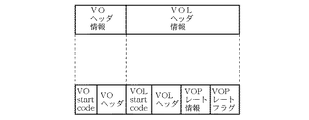
In the first embodiment, means for performing encoding based on the display speed information of an object, which is an element of the present embodiment, in the MPEG-4 video encoding system disclosed in ISO / IEC JTC11 SC29 / WG11 / N1796 And a VOP encoder including means for adding used display speed information to each object and multiplexing the encoded bit stream.
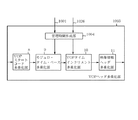
MPEG−4は動画像シーケンスを時間/空間的に任意の形状をとる動画像オブジェクトの集合体としてとらえ、各動画像オブジェクトを単位として符号化・復号を行う方式である。MPEG−4におけるビデオデータ構造を図1に示す。MPEG−4では時間軸を含めた動画像オブジェクトをビデオ オブジェクト〔Video Object(VO)〕と呼び、VOの構成要素をビデオ オブジェクト レイア〔Video Object Layer(VOL)〕と呼び、VOLの構成要素をグループ オブ ビデオ オブジェクト プレーン〔Group of Video Object Plane (GOP)〕と呼び、GOVの各時刻の状態を表し、符号化の単位となる画像データをビデオ オブジェクト プレーン〔Video Object Plane(VOP)〕と呼ぶ。VOは例えば、テレビ会議のシーンの中のそれぞれの話者や背景などに相当し、VOLはそれらの話者や背景などの固有の時間・空間解像度をもつ単位であり、VOPはそれらVOLの各時刻(=フレームに相当)における画像データである。GOVはVOPを複数集めた編集やランダムアクセスなどの単位となるデータ構造で、必ずしも符号化に用いられなくてもよい。 MPEG-4 is a system in which a moving image sequence is regarded as a set of moving image objects having an arbitrary shape in time / space, and encoding / decoding is performed for each moving image object. FIG. 1 shows a video data structure in MPEG-4. In MPEG-4, a moving image object including a time axis is called a video object [Video Object (VO)], a component of the VO is called a video object layer [Video Object Layer (VOL)], and a component of the VOL is grouped. A video object plane [Group of Video Object Plane (GOP)], which represents the state of each time of the GOV, and image data that is a unit of encoding is called a video object plane [Video Object Plane (VOP)]. The VO corresponds to, for example, each speaker or background in a video conference scene, the VOL is a unit having a unique time / spatial resolution such as the speaker or the background, and the VOP is a unit of each of the VOLs. This is image data at a time (corresponding to a frame). The GOV is a data structure that is a unit of editing, random access, and the like in which a plurality of VOPs are collected, and is not necessarily used for encoding.
VOPの具体例を図2に示す。図において、2つのVOP(VOP1は人物、VOP2は壁にかけられた絵画)を示している。各VOPはカラー濃淡レベルを表わすテクスチャデータと、VOPの形状を表わす形状データとからなる。テクスチャデータは画素あたり8ビットの輝度信号、色差信号(輝度信号に対して水平・垂直方向に1/2にサブサンプルされたサイズ)からなり、形状データはVOP内部を1、VOP外部を0とする輝度信号の画像サイズと同じ2値のマトリクスデータである。 FIG. 2 shows a specific example of the VOP. In the figure, two VOPs (VOP1 is a person, VOP2 is a painting on a wall) are shown. Each VOP is composed of texture data representing the color shading level and shape data representing the shape of the VOP. The texture data is composed of an 8-bit luminance signal and a chrominance signal (a size obtained by subsampling the luminance signal in half in the horizontal and vertical directions) per pixel. This is binary matrix data that is the same as the image size of the luminance signal to be processed.
VOPによる動画像表現において、従来のフレーム画像は複数のVOPを画面中に配置することによって得られる。ただし、動画像シーケンス中でVOが1つの場合、各VOPはフレームと同義となる。この場合は形状データは存在せず、テクスチャデータだけが符号化される。 In expressing a moving image by a VOP, a conventional frame image is obtained by arranging a plurality of VOPs on a screen. However, when there is one VO in the moving image sequence, each VOP has the same meaning as a frame. In this case, there is no shape data, and only the texture data is encoded.
以下、本実施の形態1における画像符号化装置について説明する。これはMPEG−4ビデオエンコーダをベースとしており、MPEG−4ビデオデコーダは、上記VOPを単位として符号化を実施するので、以下、VOPエンコーダと呼ぶ。既存のVOPエンコーダの動作はISO/IEC JTC1/SC29/WG11/N1796などに開示されるので、ここでは既存のVOPエンコーダそのものの説明は避け、本実施の形態1の要素を含むVOPエンコーダの説明を行う。 Hereinafter, the image encoding device according to the first embodiment will be described. This is based on the MPEG-4 video encoder, and since the MPEG-4 video decoder performs encoding in units of the above VOP, it is hereinafter referred to as a VOP encoder. Since the operation of the existing VOP encoder is disclosed in, for example, ISO / IEC JTC1 / SC29 / WG11 / N1796, the description of the existing VOP encoder itself will be avoided here, and the description of the VOP encoder including the elements of the first embodiment will be omitted. Do.
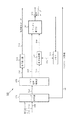
図3は本実施の形態1におけるVOPエンコーダの構成例を示すもので、110は符号化VOP決定部、111は形状符号化部、113は動き推定部、115は動き補償部、118はテクスチャ符号化部、122はメモリ、124はヘッダ多重化部、126はビデオ信号多重化部、128は減算器、129は加算器である。
FIG. 3 shows an example of the configuration of the VOP encoder according to the first embodiment.
次に動作について説明する。符号化VOP決定部110は、外部設定や符号化状況に応じて設定されるVOPレート情報7に基づき入力オブジェクト画像のうちの符号化対象となるVOPの決定を行い、符号化対象であるVOPを形状符号化部111と動き推定部113と減算器128に出力する。ここで、VOPレート情報7とは、本発明でいうところの表示速度情報に相当するものであり、VOL、GOVなどの単位の中に含まれるVOPを秒あたり何枚表示させるか(固定レート)、あるいは可変レートであるかを表わす情報を言う。
Next, the operation will be described. The coding
符号化VOP決定部110の動作について具体例を示す。固定レートとは、VOLまたはGOVなどの単位の中に含まれるVOPを秒あたり何枚表示させるかについて、該VOLまたはGOV内において常に一定である場合を示す。例えば、入力オブジェクト画像が30枚/秒、VOPレート情報7が15枚/秒であった場合、符号化VOP決定部110は入力オブジェクト画像に含まれるVOPのうち符号化対象となるVOPは1枚おきであると判断し、1枚おきに符号化対象となるVOPを出力する。
これは、秒あたり何枚表示させるかを示す情報が固定である場合を示すものであり、符号化VOP決定部110が入力オブジェクト画像に含まれるVOPのうち符号化対象となるVOPは1枚おきであると判断できる根拠は、秒あたり何枚表示させるかを示す情報が常に一定の間隔(15枚/秒)であるためである。。
また、可変レートとは固定レートでない場合を指し、VOLまたはGOPなどの単位の中に含まれるある期間(秒単位)における表示させる枚数と、前記VOLまたはGOVなどの単位の中に含まれる前記期間(秒単位)における表示させる枚数と異なる場合を示す。
A specific example of the operation of the coding
This shows a case where the information indicating how many images are displayed per second is fixed, and the encoding
Further, the variable rate indicates a case where the rate is not a fixed rate, and the number of sheets to be displayed in a certain period (second unit) included in a unit such as VOL or GOP and the period included in the unit such as VOL or GOV. This shows a case where the number of displayed images is different from the number of displayed images (in seconds).
符号化VOP決定部110によって符号化対象と特定されたVOPは、形状データをアルファブロックとよばれる16画素×16画素の領域ごとに、また、テクスチャデータをマクロブロックとよばれる16画素×16画素の領域ごとに符号化する。
The VOP specified as the encoding target by the encoding
形状符号化部111は、入力されるアルファブロックの符号化を行い、形状符号化情報112と局所復号形状情報109とを出力する。形状符号化情報112はビデオ信号多重化部126に送られ、局所復号形状情報109は動き推定部113とテクスチャ符号化部115およびテクスチャ符号化部118に入力される。動き推定部113では、メモリ122中の参照データ123aを入力し、マクロブロック単位にてブロックマッチングを行い、動き情報114を得る。この際、局所復号形状情報109に基づきマクロブロック中に含まれるオブジェクトのみを対象としたブロックマッチングにより動き情報を得る。
The
動き補償部115では、メモリ122中の動き情報114が示す位置の参照データ123bを入力し局所復号形状情報109に基づき予測画像を作成する。動き推定部115において作成された予測画像116は減算器128と加算器129に入力される。
減算器128では、予測画像116と入力マクロブロックの差分を計算し、予測誤差画像117を作成する。
テクスチャ符号化部118では、入力された予測誤差画像117をMPEG−4で定められる所定の方法で符号化し、テクスチャ符号化情報119及び局所復号予測誤差画像120を得る。この際、局所復号形状情報109に基づきブロック中に含まれるオブジェクトのみを対象とした符号化を行う。テクスチャ符号化情報119はビデオ信号多重化部126へ送られ、局所復号予測誤差画像120を加算器129へ出力する。
The
The
The
加算器129は、予測画像116と局所復号予測誤差画像120の加算を行い復号画像121を作成し、メモリ122へ書き込む。
ヘッダ多重化部124では各ヘッダ情報が多重化され、各ヘッダ情報が多重化されたビットストリーム125はビデオ信号多重化部126に入力される。
ビデオ信号多重化部126は、各ヘッダ情報が多重化されたビットストリーム125に形状符号化情報112と動き情報114とテクスチャ符号化情報119の多重化を行い、符号化VOPビットストリームを出力する。
The
Each header information is multiplexed in the
The video
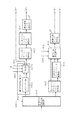
図4は図3のヘッダ多重化部の構成を示すブロック図である。図において、1はVOヘッダ多重化部、2はVOLヘッダ多重化部、3はGOVヘッダ多重化選択部、4はGOVヘッダ多重化部、5はVOPヘッダ多重化部、6はGOV多重化情報、7はVOPレート情報である。 FIG. 4 is a block diagram showing the configuration of the header multiplexing unit of FIG. In the figure, 1 is a VO header multiplexing section, 2 is a VOL header multiplexing section, 3 is a GOV header multiplexing selecting section, 4 is a GOV header multiplexing section, 5 is a VOP header multiplexing section, and 6 is GOV multiplexing information. , 7 are VOP rate information.
次に動作について説明する。VOヘッダ多重化部1では、VOヘッダ情報を多重化したビットストリームを作成し、作成したビットストリームをVOLヘッダ多重化部2に出力する。
VOLヘッダ多重化部2は、入力されたビットストリームにVOLヘッダ情報の多重化を行い、多重化後のビットストリームをGOVヘッダ多重化選択部3へ出力する。
Next, the operation will be described. The VO
The VOL
GOVヘッダ多重化選択部3では、VOLヘッダ多重化部2より出力されたビットストリームの出力先を、GOVヘッダの多重化を行うか否かを示すGOV多重化情報6に基づき判断する。GOV多重化情報6がGOVヘッダの多重化を行わないことを示す場合は、VOPヘッダ多重化部5へ、GOV多重化情報6がGOVヘッダの多重化を行うことを示す場合はGOVヘッダ多重化部4へビットストリームを出力する。
The GOV header
GOVヘッダ多重化部4は、入力されたビットストリームにVOPレート情報7を多重化し、VOPヘッダ多重化部5にビットストリームを出力する。表1は上記VOPレート情報7の一例を示すもので、4種類のVOPレートを表現する例を示している。VOPレートが30枚/秒の場合は「01」を多重化する。また直前に符号化したVOPと符号化対象のVOPが同じであれば、VOPレート情報「00」を多重化するとともに、後に続くVOPヘッダ情報とVOPデータ情報の多重化を行わない。また、VOPレートが可変である場合には、VOPレート情報「11」を多重化する。すなわち、VOPレート情報7は、VOPレートが固定であるか可変であるかを示すとともに、固定の場合のレートの値を示している。
The GOV header multiplexing unit 4 multiplexes the
VOPヘッダ多重化部5にあるVOPスタートコード多重化部8は、入力されたビットストリームにVOPスタートコードの多重化を行ったビットストリームをモジュロ・タイム・ベース(modulo _time_base) 多重化部9およびVOPタイムインクリメント(VOP_time_increment)多重化部10に出力する。
A VOP start
ここで、モジュロ・タイム・ベース13とは、図5に示すように、当該VOPがある基準時刻から何秒経過した後に表示されるかを示す情報であり、VOPタイムインクリメント14とは、同じく図5に示すように、モジュロ・タイム・ベースで定められる時刻から1000分の1秒の精度で表示時刻を微調整する情報である。すなわち、MPEG−4ではVOPの表示時刻を1000分の1秒の精度で規定することができる。
Here, as shown in FIG. 5, the modulo
VOPヘッダ多重化部5にある管理時間作成部12は、VOPレート情報7に基づきモジュロ・タイム・ベース13とVOPタイムインクリメント14とを作成し、モジュロ・タイム・ベース13をモジュロ・タイム・ベース多重化部9に、VOPタイムインクリメント14をVOPタイムインクリメント多重化部10に出力する。ただし、VOPレート情報7が可変であることを示す場合は、モジュロ・タイム・ベース13およびVOPタイムインクリメント14はVOPレート情報7に関係なく設定される。
A management
上記モジュロ・タイム・ベース多重化部9は、VOPスタートコード多重化部8より出力されたビットストリームにモジュロ・タイム・ベース13の多重化を行い、多重化後のビットストリームをVOPタイムインクリメント多重化部10へ出力する。このVOPタイムインクリメント多重化部10はモジュロ・タイム・ベース多重化部9より出力されたビットストリームに管理時間作成部12から出力されたVOPタイムインクリメント14の多重化を行い、多重化後のビットストリームを映像情報ヘッダ多重化部11へ出力する。この映像情報ヘッダ多重化部11は、VOPタイムインクリメント多重化部10より出力されたビットストリームに映像情報ヘッダの多重化を行い、多重化後のビットストリームをビデオ信号多重化部126へ出力する。
The modulo time base multiplexing unit 9 multiplexes the bit stream output from the VOP start
以上のように、この実施の形態1によればGOVヘッダにVOPレート情報を多重化するよう構成したため、デコーダ側において、各VOPヘッダのVOPスタートコードのみを解析すれば、復号化対象のVOPの復号が必要であるか否かを判断したり、複数のオブジェクトを簡単に合成したりすることを可能とするビットストリームを作成できる効果がある。 As described above, according to the first embodiment, since the VOP rate information is multiplexed in the GOV header, if only the VOP start code of each VOP header is analyzed on the decoder side, the VOP of the decoding target VOP can be obtained. There is an effect that it is possible to determine whether decoding is necessary or not, and to create a bit stream that allows a plurality of objects to be easily synthesized.
なお、図6に示すように、VOLを単位としてVOPレート情報を規定し、符号化およびVOPレート情報の多重化を行うようにしてもよい。この場合は、VOPレート情報7はVOL単位で決定され、VOLヘッダ多重化部2で多重化される。これに基づいて、モジュロ・タイム・ベース13やVOPタイムインクリメント14が決定される。
As shown in FIG. 6, VOP rate information may be defined in units of VOL, and encoding and multiplexing of VOP rate information may be performed. In this case, the
以上のように本実施の形態1においては、オブジェクト単位に画像を符号化する画像符号化装置において、所定の表示速度情報に基づいて画像を符号化する符号化手段と、該符号化手段で符号化された画像符号化信号に上記所定の表示速度情報を多重化して出力する多重化手段を備えたものの一実施例を開示した。
また、本実施の形態1においては、多重化手段は、上記表示速度情報をオブジェクトごとに多重化するものの一実施例を開示した。
As described above, in the first embodiment, in the image encoding device that encodes an image in object units, an encoding unit that encodes an image based on predetermined display speed information, An embodiment having a multiplexing means for multiplexing and outputting the predetermined display speed information to the coded image coded signal has been disclosed.
In the first embodiment, an example of the multiplexing unit that multiplexes the display speed information for each object has been disclosed.
実施の形態2.
本実施の形態2では、実施の形態1で述べたVOPエンコーダの別の実施の形態を説明する。本実施の形態2におけるVOPエンコーダは、表示速度情報としてオブジェクトの表示速度が固定速度であるか可変速度であるかを示す1ビットのVOPレートフラグとオブジェクトの表示速度の値を示すVOPレート情報との符号化を行い、ビットストリームに多重化する手段を備えたものである。
In the second embodiment, another embodiment of the VOP encoder described in the first embodiment will be described. The VOP encoder according to the second embodiment includes, as display speed information, a 1-bit VOP rate flag indicating whether the display speed of an object is a fixed speed or a variable speed, and VOP rate information indicating a value of the display speed of the object. And a means for multiplexing into a bit stream.
上記VOPレートフラグが可変速度を示す場合は、実施の形態1で述べた表1においてVOPレートが可変に相当するものであり、上記VOPレートフラグが固定速度を示す場合は、実施の形態1で述べた表1においてVOPレートが30枚/秒、あるいは15枚/秒に相当するものである。
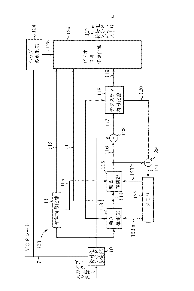
図7はこの発明の実施の形態2におけるVOPエンコーダの構成例を示すものであり、1000はヘッダ多重化部、1001はVOPレートフラグ、1026はVOPレートである。本実施の形態2におけるVOPエンコーダは、実施の形態1で述べたVOPエンコーダのヘッダ多重化部124に相当するヘッダ多重化部1000の構成動作のみが異なるので、この部分についてのみ説明する。
FIG. 7 shows a configuration example of a VOP encoder according to the second embodiment of the present invention, where 1000 is a header multiplexing unit, 1001 is a VOP rate flag, and 1026 is a VOP rate. The VOP encoder according to the second embodiment differs only in the configuration operation of the
図8はこの発明の実施の形態2におけるVOPエンコーダ部のヘッダ多重化部1000の構成を示すブロック図である。図において、1002はVOLヘッダ多重化部、1003はVOPヘッダ多重化部である。
FIG. 8 is a block diagram showing a configuration of a
次に動作について説明する。
VOヘッダ多重化部1では、VOヘッダ情報を多重化したビットストリームを作成し、作成したビットストリームをVOLヘッダ多重化部1002に出力する。VOLヘッダ多重化部1002は、入力されたビットストリームにVOLヘッダ情報の多重化を行い、多重化後のビットストリームをGOVヘッダ多重化選択部3へ出力する。この際、VOPレート情報とVOPレートフラグの多重化も行う。
Next, the operation will be described.
The VO
表2はVOPレート1026の多重化例を示す。この場合、VOPレート1026が2枚/秒の場合は「000」を、VOPレートが5枚/秒の場合は「001」を、VOPレートが25枚/秒の場合は「010」を、VOPレートが30枚/秒の場合は「011」を、また上記以外のVOPレート(例えば、VOPレートが10枚/秒)の場合は「100」をVOPレート情報として多重化する。
VOPレートフラグについては、VOPレートフラグが固定速度を示す場合は「1」を、可変速度を示す場合は「0」を多重化する。図9は、VOLヘッダ多重化部1002より出力されたビットストリームの一例を示す。
GOVヘッダ多重化選択部3では、VOLヘッダ多重化部1002より出力されたビットストリームの出力先を、GOVヘッダの多重化を行うか否かを示すGOV多重化情報6に基づき判断する。GOV多重化情報6がGOVヘッダの多重化を行わないことを示す場合は、VOPヘッダ多重化部1003へ、GOV多重化情報6がGOVヘッダの多重化を行うことを示す場合はGOVヘッダ多重化部4ヘビットストリームを出力する。
As for the VOP rate flag, "1" is multiplexed when the VOP rate flag indicates a fixed speed, and "0" is multiplexed when the VOP rate flag indicates a variable speed. FIG. 9 shows an example of a bit stream output from the VOL
The GOV header
GOVヘッダ多重化部4は、入力されたビットストリームにGOVヘッダ情報の多重化を行い、多重化後のビットストリームをVOPヘッダ多重化部1003へ出力する。図10にVOPヘッダ多重化部1003の詳細を示す。図10において、1004は管理時間作成部である。
The GOV header multiplexing unit 4 multiplexes the input bitstream with the GOV header information, and outputs the multiplexed bitstream to the VOP
次に動作について説明する。管理時間作成部1004は、入力されるVOPレートフラグ1001が固定速度を示す場合にはVOPレート1026に基づき、入力されるVOPレートフラグ1001が可変速度を示す場合にはVOPエンコーダが内部に持つタイマーに基づき、モジュロ・タイム・ベースとVOPタイムインクリメントを作成する。作成したモジュロ・タイム・ベースはモジュ口・タイム・ベース多重化部9へ、作成したVOPタイムインクリメントはVOPタイムインクリメント多重化部10へ出力する。
Next, the operation will be described. The management
VOPスタートコード多重化部8は、入力されたビットストリームにVOPスタートコードの多重化を行い、多重化後のビットストリームをモジュロ・タイム・ベース多重化部9に出力する。モジュロ・タイム・ベース多重化部9は、入力されたビットストリームにモジュロ・タイム・ベースの多重化を行い、多重化後のビットストリームをVOPタイムインクリメント多重化部10へ出力する。
The VOP start
VOPタイムインクリメント多重化部10は、入力されたビットストリームにVOPタイムインクリメントの多重化を行い、多重化後のビットストリームを映像情報ヘッダ多重化部11へ出力する。映像情報ヘッダ多重化部11は、VOPタイムインクリメント多重化部10より出力されたビットストリームに映像情報ヘッダの多重化を行い、多重化後のビットストリームをビデオ信号多重化部126へ出力する。
The VOP time
以上のように、この実施の形態2によれば、VOLレイヤにVOPレートフラグとVOPレート情報を多重化するように構成したため、デコーダ側において、VOPレートフラグとVOPレートを用いれば、ユーザが所望するVOPを瞬時に特定することができるため、各VOPヘッダのVOPスタートコードのみを解析すれば、復号化対象のVOPの復号が必要であるか否かを判断したり、複数のオブジェクトを簡単に合成したりすることを可能とするビットストリームを作成できる効果がある。
なお、VOPレートフラグのみを多重しても、可変、固定速度か否かの識別ができるので、復号化対象のVOPの復号処理が行えるものである。
As described above, according to the second embodiment, the VOP rate flag and the VOP rate information are configured to be multiplexed in the VOL layer. Since the VOP to be decoded can be specified instantaneously, if only the VOP start code of each VOP header is analyzed, it is possible to determine whether or not the VOP to be decoded needs to be decoded, and to easily determine a plurality of objects. There is an effect that a bit stream that can be combined can be created.
Note that even if only the VOP rate flag is multiplexed, it is possible to identify whether the speed is variable or fixed, so that the VOP to be decoded can be decoded.
以上のように本実施の形態2においては、オブジェクト単位に画像を符号化する画像符号化装置において、オブジェクトの表示速度が固定速度であるか可変速度であるかを示すフラグの符号化手段と、該符号化手段で符号化された画像符号化信号に上記フラグを多重化して出力する多重化手段と、所定の表示速度情報に基づいて画像を符号化する符号化手段と、該符号化手段で符号化された画像符号化信号に上記所定の表示速度情報を多重化して出力する多重化手段とを備えたものの一実施例を開示した。 As described above, in the second embodiment, in the image encoding device that encodes an image in object units, a flag encoding unit that indicates whether the display speed of the object is a fixed speed or a variable speed, A multiplexing unit that multiplexes the flag with the image-encoded signal encoded by the encoding unit and outputs the multiplexed flag; an encoding unit that encodes an image based on predetermined display speed information; An embodiment has been disclosed which includes multiplexing means for multiplexing and outputting the predetermined display speed information to the coded image coded signal.
実施の形態3.
本実施の形態3では、符号化ビットストリーム中から実施の形態1で述べたVOPレート情報を復号し出力するための画像復号化装置、すなわちMPEG−4ビデオデコーダ(以下、VOPデコーダと呼ぶ)を各オブジェクトに対応して複数備え、複数の復号されたオブジェクトを合成して画像を再生するシステムについて説明する。
In the third embodiment, an image decoding apparatus for decoding and outputting the VOP rate information described in the first embodiment from an encoded bit stream, that is, an MPEG-4 video decoder (hereinafter, referred to as a VOP decoder). A system in which a plurality of objects are provided corresponding to the respective objects and a plurality of decoded objects are combined to reproduce an image will be described.
まず、本実施の形態3における画像復号化装置(VOPデコーダ)の構成と動作について説明する。既存のVOPデコーダの動作はISO/IEC JTC1/SC29/WG11/N1796などに開示されるので、ここでは既存のVOPデコーダそのものの説明は避け、本実施の形態3の要素を含むVOPデコーダの説明を行う。本実施の形態3におけるVOPデコーダは、実施の形態1に述べたVOPエンコーダで生成される符号化ビットストリームを復号可能なデコーダである。 First, the configuration and operation of the image decoding device (VOP decoder) according to the third embodiment will be described. Since the operation of the existing VOP decoder is disclosed in ISO / IEC JTC1 / SC29 / WG11 / N1796 or the like, the description of the existing VOP decoder itself is avoided here, and the description of the VOP decoder including the elements of the third embodiment will be described. Do. The VOP decoder according to the third embodiment is a decoder that can decode the coded bit stream generated by the VOP encoder described in the first embodiment.
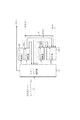
図11は、この発明の実施の形態3におけるVOPデコーダの内部構成例を示したものである。VOPのデコーダは実施の形態1および図2に示したように、テクスチャデータと形状データとからなるものとし、本デコーダはこれらを圧縮符号化したデータを入力としてそれぞれのデータを復元する機能を持つものとする。図において、150は符号化VOPビットストリーム、151はヘッダ解析部、152はヘッダ情報が解析されたビットストリーム、153はビデオ信号解析部、154は形状符号化データ、155は形状復号部、156は復号形状データ、157はテクスチャ符号化データ、158は動き情報、159は動き補償部、160は予測テクスチャデータ、161はテクスチャ復号部、162は復号テクスチャデータ、164はメモリ、165は参照データである。
FIG. 11 shows an example of the internal configuration of the VOP decoder according to the third embodiment of the present invention. As shown in
以下、同図をもとに動作について詳述する。符号化VOPビットストリーム150はヘッダ解析部151に入力され、所定のシンタックスにしたがってヘッダ情報が解析される。ヘッダ解析部151においてヘッダ情報が解析されたビットストリーム152はビデオ信号解析部153に入力され、形状符号化データ154とテクスチャ符号化データ157と動き情報158とに解析される。形状復号部155は入力される形状符号化データ154の復号を行い、復号形状データ156を出力する。
動き補償部159はメモリ164中の参照データ165とビデオ信号解析部153から入力される動き情報158から予測テクスチャデータ160を出力する。テクスチャ復号部161は、テクスチャ符号化データ157と予測テクスチャデータ160とに基づいてMPEG−4で定められる所定の方法で画像データに復元し、復号テクスチャデータ162を生成する。この復号テクスチャデータ162は以降のVOPの復号に用いられるので、メモリ164に書き込まれる。
Hereinafter, the operation will be described in detail with reference to FIG. The encoded
The
図12はこの発明の実施の形態3の特徴であるヘッダ解析部151の内部構成を示したものである。図において、51はスタートコード解析部、52はVOヘッダ解析部、53はVOLヘッダ解析部、54はGOVヘッダ解析部、58はVOPレート情報、55はVOPヘッダ解析部である。本実施の形態3におけるヘッダ解析部151は、GOVヘッダ解析部54において当該GOVに含まれるVOPのVOPレート情報58をビットストリーム中から復号してこれを外部へ出力することを特徴とする。このVOPレート情報58の使用方法は後述する。
FIG. 12 shows the internal configuration of the
スタートコード解析部51は、入力される符号化VOPビットストリーム150に含まれるスタートコードの解析を行う。解析したスタートコードがVOを示すものであればVOヘッダ解析部52へ、解析したスタートコードがVOLを示すものであればVOLヘッダ解析部53へ、解析したスタートコードがGOVを示すものであればGOVヘッダ解析部54へ、解析したスタートコードがVOPを示すものであればVOPヘッダ解析部55へビットストリームを出力する。なお、VOPヘッダ解析部55の解析処理を終了した後、ビットストリームはビデオ信号解析部153に出力される。
The start
VOヘッダ解析部52は、入力されるビットストリームよりVOヘッダ情報の解析を行い、解析を終えたビットストリームをスタートコード解析部51へ出力する。VOLヘッダ解析部53は、入力されるビットストリームよりVOLヘッダ情報の解析を行い、解析を終えたビットストリームをスタートコード解析部51へ出力する。GOVヘッダ解析部54は、入力されるビットストリームよりGOVヘッダ情報の解析を行い、解析を終えたビットストリームをスタートコード解析部51へ出力する。この際、GOVヘッダ情報中に含まれるVOPレート情報58を復号して出力する。VOPヘッダ解析部55は、入力されるビットストリームよりVOPヘッダ情報の解析を行い、解析を終えたビットストリームをスタートコード解析部51を介してビデオ信号解析部153へ出力する。
The VO
以上の構成と動作によるVOPデコーダによれば、GOVの単位でそれに含まれるVOPのVOPレート情報を出力させることができる。この情報を用いて複数のオブジェクトを合成するシステムを図13に示す。図において、200は符号化VOPビットストリームa、201は符号化VOPビットストリームb、202は符号化VOPビットストリームc、203aは符号化VOPビットストリームa200を復号するVOPデコーダ部、203bは符号化VOPビットストリームb201を復号するVOPデコーダ部、203cは符号化VOPビットストリームc202を復号するVOPデコーダ部、204は復号オブジェクト画像a、205は復号オブジェクト画像b、206は復号オブジェクト画像c、207はVOPレート情報a,208はVOPレート情報b、209はVOPレート情報c、210はコンポジション部、211は復号画像である。復号オブジェクト画像とは、各VOPの復号形状データ156と対応する復号テクスチャデータ162とをまとめ、かつ、これをVOPをまとめる単位(例えばGOV,VOLなど)でまとめたものを指すものとする。
According to the VOP decoder having the above configuration and operation, it is possible to output the VOP rate information of the VOP included in the GOV in GOV units. FIG. 13 shows a system for synthesizing a plurality of objects using this information. In the figure, 200 is an encoded VOP bit stream a, 201 is an encoded VOP bit stream b, 202 is an encoded VOP bit stream c, 203a is a VOP decoder unit for decoding the encoded VOP bit stream a200, and 203b is an encoded VOP bit stream. A VOP decoder section for decoding the bit stream b201, 203c is a VOP decoder section for decoding the encoded VOP bit stream c202, 204 is a decoded object image a, 205 is a decoded object image b, 206 is a decoded object image c, and 207 is a VOP rate. Information a and 208 are VOP rate information b, 209 is VOP rate information c, 210 is a composition unit, and 211 is a decoded image. The decoded object image refers to an image in which the decoded
符号化VOPビットストリームa200〜c202はそれぞれ対応するVOPデコーダ部203a〜203cで復号され、復号VOP画像a204〜c206が生成される。この際、各VOPデコーダ部は対応するVOPレート情報a207〜c209を復号してこれをコンポジション部210に出力する。コンポジション部210は、同VOPレート情報a207〜c209に基づいて、各復号VOP画像を、復号画像211のいずれの時刻の画像フレームに合成するかを決定して、対応する時刻の画像フレームにマッピングする。例えば、復号画像211が1秒あたり30枚(これは通常のテレビ信号の表示速度に相当する)で表示されるものとする。更に以下の状況を想定する。
○復号VOP画像a204が1秒あたり5枚で表示(即ち、VOPレート情報a207が5枚/秒を表わす)。
○復号VOP画像b205が1秒あたり10枚で表示(即ち、VOPレート情報b208が10枚/秒を表わす)。
○復号VOP画像c206が1秒あたり15枚で表示(即ち、VOPレート情報c209が15枚/秒を表わす)。
この場合、復号画像211の各秒の先頭の画像フレームには復号VOP画像a204〜c206のすべてがマッピングされ、各秒の先頭から5枚おきの画像フレームに復号VOP画像a204がマッピングされ、各秒の先頭から10枚おきの画像フレームに復号VOP画像b205がマッピングされ、各秒の先頭から15枚おきの画像フレームに復号VOP画像c206がマッピングされる、という動作を行うことができる。これによって、複数の映像オブジェクトを各々の表示速度に合わせて画像フレームに合成した映像を表示することができる。
The encoded VOP bit streams a200 to c202 are decoded by the corresponding VOP decoder units 203a to 203c, respectively, to generate decoded VOP images a204 to c206. At this time, each VOP decoder unit decodes the corresponding VOP rate information a207 to c209 and outputs this to the
The decoded VOP image a204 is displayed at 5 frames per second (that is, the VOP rate information a207 indicates 5 frames / sec).
The decoded VOP image b205 is displayed at 10 frames per second (that is, the VOP rate information b208 indicates 10 frames / second).
The decoded VOP image c206 is displayed at 15 frames per second (that is, the VOP rate information c209 indicates 15 frames / second).
In this case, all of the decoded VOP images a204 to c206 are mapped to the first image frame of each second of the decoded
以上のように、GOVのレイヤにVOPレート情報を符号化した符号化ビットストリームを復号するVOPデコーダを用いることにより、簡易な構成で複数のオブジェクトを合成して再生画像を得るシステムを実現することが可能である。
なお、VOPレート情報はVOLを単位として画像符号化装置側で符号化されていてもよい。この場合、画像復号化装置側では、VOLを単位として符号化されたVOPレート情報を復号化し、VOLを単位として上述したような簡易な複数のオブジェクトの合成が可能である。
As described above, by using a VOP decoder that decodes an encoded bit stream obtained by encoding VOP rate information in a GOV layer, a system that obtains a reproduced image by combining a plurality of objects with a simple configuration is realized. Is possible.
Note that the VOP rate information may be encoded on the image encoding device side in VOL units. In this case, the image decoding device side can decode the VOP rate information encoded in units of VOL, and synthesize a plurality of simple objects as described above in units of VOL.
また、本実施の形態3では複数のオブジェクトを合成するシステムとしてVOPデコーダを用いたが、1つのオブジェクトだけを復号し再生するシステムにおいて1つのVOPデコーダだけを使用するような構成も可能である。
以上のように本実施の形態3においては、オブジェクト単位に画像を符号化した符号化ビットストリームを復号化する画像復号化装置において、上記符号化ビットストリームから表示速度情報を復号する表示速度情報復号手段と、該表示速度情報復号手段によって復号された表示速度情報に基づいてオブジェクト単位で処理された画像の再生処理を制御する制御手段を備えるものの一実施例を開示した。
また、本実施の形態3においては、表示速度情報復号手段は、上記表示速度情報をオブジェクトごとに復号するものの一実施例を開示した。
Further, in the third embodiment, a VOP decoder is used as a system for synthesizing a plurality of objects, but a configuration in which only one VOP decoder is used in a system for decoding and reproducing only one object is also possible.
As described above, according to the third embodiment, in an image decoding device that decodes an encoded bit stream obtained by encoding an image in object units, display speed information decoding that decodes display speed information from the encoded bit stream An embodiment has been disclosed which comprises means and control means for controlling a reproduction process of an image processed on an object basis based on the display speed information decoded by the display speed information decoding means.
Also, in the third embodiment, an example in which the display speed information decoding unit decodes the display speed information for each object has been disclosed.
実施の形態4.
本実施の形態4では、実施の形態3で述べたVOPデコーダの別の実施の形態を説明する。本実施の形態4におけるVOPデコーダは、デコーダが想定するVOPレートの値に基づいて、復号対象となるVOPを特定して復号する機能を持つものとする。
本実施の形態4のVOPデコーダは、実施の形態2で述べたVOPデコーダのヘッダ解析部151の構成動作のみが異なるので、この部材についてのみ説明する。
Embodiment 4 FIG.
In the fourth embodiment, another embodiment of the VOP decoder described in the third embodiment will be described. The VOP decoder according to the fourth embodiment has a function of specifying a VOP to be decoded and decoding based on the value of the VOP rate assumed by the decoder.
The VOP decoder according to the fourth embodiment differs from the VOP decoder according to the second embodiment only in the configuration operation of the
図14はこの発明の実施の形態4によるVOPデコーダ部のヘッダ解析部の構成を示すブロック図であり、エンコーダ側のVOPレートとデコード側のVOPレートが不一致の場合である。図において、59はデコードVOP選択部であり、GOVヘッダ解析部54から出力されたVOPレート58とデコード側で想定したVOPレート61とを対比してVOP選択情報62を出力する。また、VOPヘッダ解析部55は時間管理情報ヘッダ解析部56、映像情報ヘッダ解析部57の他にカウンター部60を有する。
FIG. 14 is a block diagram showing a configuration of a header analysis unit of a VOP decoder unit according to Embodiment 4 of the present invention, where the VOP rate on the encoder side does not match the VOP rate on the decode side. In the figure,
次に動作について説明する。デコードVOP選択部59は、GOVヘッダ解析部54において解析されたVOPレート58とデコーダ側が想定するVOPレート61との比較に基づき復号化を行うVOPの情報を示すVOP選択情報62をVOPヘッダ解析部55のカウンター部60へ出力する。このカウンター部60は入力されたビットストリームに含まれるVOPスタートコードに続くVOPヘッダ情報の復号を行うか否かをVOP選択情報62に基づき判断する。
Next, the operation will be described. The decoding
具体的には、GOVヘッダ解析部55において解析されたVOPレート58が30枚/秒、デコーダ側が想定するVOPレートが15枚/秒の場合は、1VOPおきに解析を行うVOPがあることを示すVOP選択情報62をVOPヘッダ解析部55にあるカウンター部60に出力する。カウンター部60では、まず、VOPヘッダが入力される毎にカウンター60aでカウントする。
Specifically, when the
次いで判定器60bは、カウンター60aから入力されるカウント数とデコータVOP選択部59から入力されるVOPレート選択情報62に基づき、入力されるVOPの解析を行う必要があるか否かを判定する。入力されるVOPの解析を行う必要があると判定した場合は、入力されるビットストリームを時間管理情報ヘッダ解析部56へ出力する。また、入力されるVOPの解析を行う必要がないと判定した場合は、入力されるビットストリームをスタートコード解析部51に出力する。
Next, the determiner 60b determines whether or not it is necessary to analyze the input VOP based on the count number input from the
以下に具体例を示す。VOPレート選択情報62が3枚のVOPに対して1枚のVOPを解析する必要があるという情報である場合、判定器60bでは、カウンター60aより入力されるカウント数を3で割った余りが0となる場合を解析必要なVOPと判断し、カウンター60aより入力されるカウント数を3で割った余りが1または2の場合を解析不必要なVOPと判断する。
なお、本実施の形態4では、GOVヘッダにVOPレート情報が含まれる場合に対応するVOPデコーダについて述べたが、実施の形態2で述べたように、VOPレート情報がVOLヘッダ中に含まれていてもよい。その場合は、図15に示すように、VOLヘッダ解析部300にVOPレート情報58の復号機能を持たせればよい。
また、本実施の形態4における、VOPデコーダは、複数のオブジェクトを合成するシステムでも、1つのオブジェクトだけを復号し再生するシステムでも使用することが可能である。
Specific examples are shown below. If the VOP
In the fourth embodiment, the VOP decoder corresponding to the case where the GOV header includes the VOP rate information has been described. However, as described in the second embodiment, the VOP rate information is included in the VOL header. May be. In that case, as shown in FIG. 15, the
Further, the VOP decoder according to the fourth embodiment can be used in a system that combines a plurality of objects or a system that decodes and reproduces only one object.
以上のように、本実施の形態4においては、制御手段は、上記表示速度情報復号手段によって復号されたオブジェクトの表示速度情報と、復号化装置において予め設定されたオブジェクトの表示速度情報とに基づいて、該オブジェクトにおいて復号対象となる時刻を特定する復号時刻特定手段と、該復号時刻特定手段によって得られる復号対象時刻に基づいてオブジェクトの復号を行う復号化手段とを備えるものの一実施例を開示した。 As described above, in the fourth embodiment, the control unit performs the processing based on the display speed information of the object decoded by the display speed information decoding unit and the display speed information of the object preset in the decoding device. An embodiment of the present invention includes a decoding time specifying unit that specifies a time to be decoded in the object, and a decoding unit that decodes the object based on the decoding target time obtained by the decoding time specifying unit. did.
実施の形態5.
本実施の形態5では、実施の形態3または実施の形態4で述べたVOPデコーダの別の実施の形態を説明する。本実施の形態5におけるVOPデコーダは、オブジェクトの表示速度が固定速度であるか可変速度であるかを示すVOPレートフラグとオブジェクトの表示速度を示すVOPレート情報とユーザが外部より設定する時刻情報を示す外部設定表示制御情報とタイムコードとに基づいて、復号対象となるVOPを特定して復号する機能を持つものとする。
In the fifth embodiment, another embodiment of the VOP decoder described in the third embodiment or the fourth embodiment will be described. The VOP decoder according to the fifth embodiment stores a VOP rate flag indicating whether the display speed of an object is a fixed speed or a variable speed, VOP rate information indicating the display speed of an object, and time information set externally by a user. It has a function of specifying a VOP to be decoded and decoding based on the external setting display control information and the time code shown.
本実施の形態5のVOPデコーダは、図16に示すように実施の形態3で述べたVOPデコーダのヘッダ解析部151に相当するヘッダ解析部1005の構成動作のみが異なるので、この部分についてのみ説明する。
図17はこの実施の形態によるVOPデコーダ部のヘッダ解析部1005の構成を示すブロック図である。図において、1006はVOLヘッダ解析部、1007はGOVヘッダ解析部、1008はVOPヘッダ解析部、1009は外部設定表示制御情報、1010はVOPレートフラグ、1011はタイムコードである。なお、外部設定表示制御情報1009は、絶対時刻を示す情報であっても良いし、何枚のVOPに対して1枚のVOPを復号する必要があるかを示すVOP選択情報であっても良い。
The VOP decoder according to the fifth embodiment differs from the VOP decoder according to the third embodiment only in the configuration operation of the
FIG. 17 is a block diagram showing the configuration of the
次に動作について説明する。スタートコード解析部51は、入力される符号化VOPビットストリームに含まれるスタートコードの解析を行う。解析したスタートコードがVOを示すものであればVOヘッダ解析部52へ、解析したスタートコードがVOLを示すものであればVOLヘッダ解析部1006へ、解析したスタートコードがGOVを示すものであればGOVヘッダ解析部1007へ、解析したスタートコードがVOPを示すものであればVOPヘッダ解析部1008ヘビットストリームを出力する。なお、VOPヘッダ解析部1008の解析処理を終了した後、ビットストリームはビデオ信号解析部153に出力される。
Next, the operation will be described. The start
次に上記のVOヘッダ解析部52は、入力されるビットストリームよりVOヘッダの解析を行い、解析を終えたビットストリームをスタートコード解析部51へ出力する。
また、VOLヘッダ解析部1006は、入力されるビットストリームよりVOLヘッダとVOPレート情報58とVOPレートフラグ1010の解析を行い、解析を終えたビットストリームをスタートコード解析部51へ出力するとともに、VOPレート情報58をコンポジション部210とVOPヘッダ解析部1008へ、VOPレートフラグ1010をVOPヘッダ解析部1008へ出力する。
Next, the VO
The VOL
GOVヘッダ解析部1007は、入力されるビットストリームよりGOVへッダの解析を行い、解析を終えたビットストリームをスタートコード解析部51へ出力するとともに、解析されたGOVヘッダに含まれるタイムコード1011をVOPヘッダ解析部1008へ出力する。
The GOV
図18は、VOPヘッダ解析部1008の詳細を示す図である。1012は復号VOP決定部(1)であり、カウンター部1012a、判定器1012bを有する。1013はモジュロ・タイム・ベース解析部、1014はVOPタイムインクリメント解析部、1015は復号VOP決定部(2)、1016は復号VOP決定方法選択部である。
FIG. 18 is a diagram showing details of the VOP
次に動作について説明する。復号VOP決定方法選択部1016では、VOPレートフラグ1010に基づき、入力されるビットストリームの出力先を選択する。VOPレートフラグ1010が固定速度を示す場合には復号VOP決定部(1)1012を、VOPレートフラグ1010が可変速度を示す場合にはモジュロ・タイム・ベース解析部1013を出力先とする。
Next, the operation will be described. The decoding VOP determination
まず、VOPレートフラグ1010が固定速度を示す場合について説明する。復号VOP決定部(1)1012にあるカウンター部1012aは、スタートコード解析部51においてVOPスタートコードが検出されてVOPヘッダ解析部1006にビットストリームが入力される度にカウント数をインクリメントし、カウント数とビットストリームを判定器1012bに出力する。
次いで判定器1012bでは復号対象VOPの復号を行う必要があるか否かの判定を行う。判定器1012bの動作について、外部設定表示制御情報1009が絶対時刻で与えられた場合を第一のケース、外部設定表示制御情報1009がVOP選択情報で与えられた場合を第二のケースとして下記に説明する。
First, a case where the
Next, the determiner 1012b determines whether it is necessary to decode the VOP to be decoded. Regarding the operation of the determiner 1012b, the case where the external setting
(第一のケース)
カウンター部1012aより入力されるカウント数とVOPレート情報58とタイムコード1011とに基づき、復号対象VOPが持つ絶対時刻を算出する。例えば、カウント数が4、VOPレート情報が2枚/秒を示し、絶対時刻が0h10m0sec0msecである場合、復号対象VOPが持つ絶対時刻は0h10m02sec0msecと算出される。算出した復号対象VOPが持つ絶対時刻と外部設定表示制御情報1009とが等しければ、復号を行う必要があると判断する。
(First case)
The absolute time of the decoding target VOP is calculated based on the count number input from the counter unit 1012a, the
一方、等しくない場合は、次に復号対象となるVOPの絶対時刻を算出する。これは、次に復号対象となるVOPの絶対時刻と、現在復号対象とされているVOPの絶対時刻とを比較して、より外部設定表示制御情報1009に近い絶対時刻を持つVOPを復号するようにするためである。次に復号対象となるVOPの絶対時刻は、すでに算出した現在復号対象とされているVOPの絶対時刻とVOPレート情報58とから算出する。この算出値が外部設定表示制御情報1009を超えない、もしくは等しい場合は、次に復号対象となるVOPを復号するものと判断し、現在復号対象とされているVOPの復号は行わない。また、算出値が外部設定表示制御情報1009を超える場合には、
○現在復号対象とされているVOPを復号
○次に復号対象となるVOPを復号(=現在復号対象とされているVOPは復号しない)
○外部設定表示制御情報1009との差が小さい、つまり外部設定表示制御情報1009に近い絶対時刻をもつVOPを復号
のいずれを選択してもよい。
On the other hand, if they are not equal, the absolute time of the next VOP to be decoded is calculated. This is so that the absolute time of the VOP to be decoded next is compared with the absolute time of the VOP currently being decoded, and a VOP having an absolute time closer to the external setting
○ Decode the VOP currently being decoded ○ Decode the next VOP to be decoded (= Do not decode the VOP currently being decoded)
O Decoding of a VOP having a small difference from the external setting
(第二のケース)
VOPデコーダ側において表示速度を制御する場合であり、例えば、ユーザが表示速度を決めることが可能となったり、CPUリソースに応じて最適な表示速度を指定することが可能となる。
(Second case)
This is a case where the display speed is controlled on the VOP decoder side. For example, it is possible for the user to determine the display speed or to specify the optimum display speed according to the CPU resources.
次に動作について説明する。VOP選択情報が3枚のVOPに対して1枚のVOPを復号する必要があるという情報である場合を想定する。この場合、判定器1012bは、カウンター部1012aより入力されるカウント数を3で割った余りが0となる場合を復号を行う必要があるVOPと判断し、カウンター部1012aより入力されるカウント数を3で割った余りが1または2の場合を復号を行う必要がないVOPと判断する。 Next, the operation will be described. It is assumed that the VOP selection information is information indicating that one VOP needs to be decoded for three VOPs. In this case, the determiner 1012b determines that the remainder obtained by dividing the count number input from the counter unit 1012a by 3 is 0 as a VOP that requires decoding, and determines the count number input from the counter unit 1012a. When the remainder obtained by dividing by 3 is 1 or 2, it is determined that the VOP does not need to be decoded.
第一のケース、第二のケースとも、復号対象VOPの復号を行う必要があると判断した場合には、ビットストリームをモジュロ・タイム・ベース解析部1013へ、復号を行う必要がないと判断した場合には、入力されるビットストリームをスタートコード解析部51に出力する。モジュロ・タイム・ベース解析部1013ではモジュロ・タイム・ベースの解析を行い、VOPタイムインクリメント解析部1014ヘビットストリームを出力する。
VOPタイムインクリメント解析部1014ではVOPタイムインクリメントの解析を行い、映像情報ヘッダ解析部57ヘビットストリームを出力する。映像情報ヘッダ解析部57では映像情報ヘッダの解析を行い、スタートコード解析部51ヘビットストリームを出力する。
In both the first case and the second case, when it is determined that the decoding target VOP needs to be decoded, it is determined that the bit stream need not be decoded by the modulo time
The VOP time
次に、VOPレートフラグ1010が可変速度を示す場合について説明する。モジュロ・タイム・ベース解析部1013ではモジュロ・タイム・ベースの解析を行い、VOPタイムインクリメント解析部1014ヘビットストリームを出力する。VOPタイムインクリメント解析部1014ではVOPタイムインクリメントの解析を行い、復号VOP決定部(2)1015ヘビットストリームを出力する。
Next, a case where the
復号VOP決定部(2)1015は、モジュロ・タイム・ベース解析部1013において解析されたモジュロ・タイム・ベースと、VOPタイムインクリメント解析部1014において解析されたVOPタイムインクリメントと、タイムコード1011とに基づき、復号対象VOPが持つ絶対時刻を作成し、作成した絶対時刻と外部設定表示制御情報1009とに基づき、復号対象VOPの復号を行う必要があるか否かを判定する。復号を行う必要があると判断した場合は、ビットストリームを映像情報ヘッダ解析部57へ、復号を行う必要がないと判断した場合には、ビットストリームをスタートコード解析部51に出力する。映像情報ヘッダ解析部57では映像情報ヘッダの解析を行い、スタートコード解析部51ヘビットストリームを出力する。
The decoding VOP determination unit (2) 1015 is based on the modulo time base analyzed by the modulo time
以上のように、この実施の形態5によれば、VOLレイヤにVOPレートフラグとVOPレート情報を符号化したビットストリームを解析可能とするよう構成したため、VOPレートフラグとVOPレートとを用いれば、ユーザが所望するVOPを瞬時に特定することができ、各VOPヘッダ情報に含まれるVOPスタートコードのみを解析することにより、復号化対象のVOPの復号が必要であるか否かを判断したり、複数のオブジェクトを簡単に合成したりすることができる効果がある。
なお、VOPデコーダに入力される符号化VOPビットストリームに含まれるVOPが全てイントラ符号化されている場合には、ユーザが所望するVOPを瞬時に特定し、表示させることも可能となる効果もある。
As described above, according to the fifth embodiment, the VOL layer is configured to be able to analyze the bit stream obtained by encoding the VOP rate flag and the VOP rate information. Therefore, if the VOP rate flag and the VOP rate are used, A VOP desired by the user can be specified instantaneously, and by analyzing only the VOP start code included in each VOP header information, it can be determined whether or not the VOP to be decoded needs to be decoded. There is an effect that a plurality of objects can be easily synthesized.
When all the VOPs included in the coded VOP bit stream input to the VOP decoder are intra-coded, there is an effect that a user can instantly specify and display a desired VOP. .
以上のように、本実施の形態5においては、制御手段は、該表示速度情報復号手段によって復号された表示速度識別情報が固定を示す場合は表示速度情報に基づいて、可変速度を示す場合は各時刻の画像ごとに多重化される表示時刻情報に基づいて各時刻の画像の表示時刻を特定して再生を特徴とするものの一実施例を開示した。 As described above, in the fifth embodiment, the control unit performs control based on the display speed information when the display speed identification information decoded by the display speed information decoding unit indicates a fixed speed, An embodiment has been disclosed in which the display time of an image at each time is specified based on the display time information multiplexed for each image at each time, and reproduction is characterized.
実施の形態6.
本実施の形態6では、実施の形態5で述べたVOPデコーダの別の実施の形態を説明する。本実施の形態6におけるVOPデコーダは、オブジェクトの表示速度が固定速度であるか可変速度であるかを示すVOPレートフラグとオブジェクトの表示速度を示すVOPレートとユーザが外部より設定する時刻情報を示す外部設定表示制御情報とタイムコードとに基づいて、復号対象となるVOPを特定して復号する機能を持つものとする。
In the sixth embodiment, another embodiment of the VOP decoder described in the fifth embodiment will be described. The VOP decoder according to the sixth embodiment indicates a VOP rate flag indicating whether the display speed of an object is a fixed speed or a variable speed, a VOP rate indicating the display speed of an object, and time information externally set by a user. It has a function of specifying and decoding a VOP to be decoded based on the external setting display control information and the time code.
図19は、この発明の実施の形態6におけるヘッダ解析部を示す図である。本実施の形態6のVOPデコーダは、実施の形態5で述べたヘッダ解析部にあるVOLヘッダ解析部1006とVOPヘッダ解析部1008の構成動作のみが異なるので、この部材についてのみ説明する。
VOLヘッダ解析部1017は、入力されるビットストリームよりVOLヘッダとVOPレート情報とVOPレートフラグの解析を行い、解析を終えたビットストリームをスタートコード解析部51へ、VOPレートフラグ1010をVOPヘッダ解析部1018へ出力するとともに、解析したVOPレート情報が何らかの固定レート値であるということを示す場合(例えば、表2においてVOPレート情報「100」が示すVOPレート)はVOPレート情報58をVOPヘッダ解析部1018へ、解析したVOPレート情報がある固有値を示す場合(例えば、表2においてVOPレート情報「000」、「001」、「010」、「011」が示すVOPレート)はVOPレート情報58をVOPヘッダ解析部1018とコンポジション部210へ出力する。
FIG. 19 shows a header analysis unit according to the sixth embodiment of the present invention. The VOP decoder according to the sixth embodiment differs only in the configuration operation of the VOL
The VOL
図20は、VOPヘッダ解析部1018の詳細を示す図である。1025は復号VOP決定方法選択部、1019は復号VOP決定部(3)であり、カウンター部1019a、カウント数判定部1019b、判定器1019cを有する。1020は時間情報保持部、1021はVOPレート情報算出部、1022はVOPレート情報保持部、1023はモジュロ・タイム・ベース解析部、1024はVOPタイムインクリメント解析部である。
FIG. 20 is a diagram illustrating details of the VOP
復号VOP決定方法選択部1025では、入力されるVOPレートフラグ1010とVOPレート情報58とに基づき入力されるビットストリームの出力先を選択する。具体的には、VOPレートフラグ1010が固定速度を示しVOPレート情報58が何らかの固定レート値を示す場合には復号VOP決定部(3)1019を出力先とする。また、VOPレートフラグ1010が可変速度を示す場合は、実施の形態5に記した通りの動作となるので、説明を省略する。また、VOPレートフラグ1010が固定速度を示しVOPレート情報58がある固有値を示す場合は、復号VOP決定部(1)1012ヘビットストリームを出力する。この場合、復号VOP決定部(1)1012以降の動作は、実施の形態5に記した通りの動作となるので、説明を省略する。
従って、VOPレートフラグ1010が固定速度を示しVOPレート情報58が何らかの固定レート値を示す場合について、下記に説明する。
The decoding VOP determination
Accordingly, a case where the
復号VOP決定部(3)1019にあるカウンター部1019aは、スタートコード解析部51においてVOPスタートコードが検出されてVOPヘッダ解析部1018にビットストリームが入力される度にカウント数をインクリメントし、カウント数とビットストリームをカウント数判定部1019bに出力する。カウント数判定部1019bでは、カウント数が1枚目のVOP、または2枚目のVOPを示す場合、モジュロ・タイム・ベース解析部1023にビットストリームとカウント数を出力し、上記以外の場合には判定器1019cにビットストリームとカウント数を出力する。
The counter unit 1019a in the decoding VOP determination unit (3) 1019 increments the count number each time a VOP start code is detected by the start
モジュロ・タイム・ベース解析部1023では、モジュロ・タイム・ベースの解析を行い、入力されたカウント数が1枚目のVOPを示す場合には時間情報保持部1020へ、入力されたカウント数が2枚目のVOPを示す場合にはVOPレート情報算出部1021ヘモジュロ・タイム・ベースを出力するとともにビットストリームとカウント数をVOPタイムインクリメント解析部1024へ出力する。
VOPタイムインクリメント解析部1024では、VOPタイムインクリメントの解析を行い、入力されたカウント数が1枚目のVOPを示す場合には時間情報保持部1020へ、入力されたカウント数が2枚目のVOPを示す場合にはVOPレート情報算出部1021へVOPタイムインクリメントを出力するとともに、映像情報ヘッダ解析部57へビットストリームを出力する。映像情報ヘッダ解析部57では映像情報ヘッダの解析を行い、スタートコード解析部51ヘビットストリームを出力する。
The modulo time
The VOP time
時間情報保持部1020では、入力されるモジュロ・タイム・ベースとVOPタイムインクリメントとを保持する。VOPレート情報算出部1021は、2枚目のVOPに関するモジュロ・タイム・ベースとVOPタイムインクリメントとが入力されると、時間情報保持部1020より1枚目のVOPに関するモジュロ・タイム・ベースと同じく1枚目のVOPに関するVOPタイムインクリメントとを入力し、これらに基づきVOPレート情報を算出し、VOPレート情報保持部1022へVOPレート情報を出力する。VOPタイムインクリメントを6ビット精度にて表現した場合において、VOPレート情報算出部1021におけるVOPレート情報の算出に関する具体例を下記に示す。
The time
1枚目のVOPに関するモジュロ・タイム・ベースが「10」、1枚目のVOPに関するVOPタイムインクリメントが「000000」(即ち、1枚目のVOPに関する時刻情報は1.0秒)、2枚目のVOPに関するモジュロ・タイム・ベースが「10」、2枚目のVOPに関するVOPタイムインクリメントが「100000」(即ち、2枚目のVOPに関する時刻情報は1.5秒)の場合、両者の時間情報の差分は0.5秒となる。これは、0.5秒に1枚の割合にて復号対象のVOPが存在すること、即ちVOPレートは2枚/秒である(表2を用いればVOPレート情報は「1111」)ことを意味する。
なお、VOPレート情報58が多重化されていない場合でも、VOPレートフラグ1010さえ多重化されていれば、これによって固定レートであることが判断できるので、上記のような動作が可能である。
The modulo time base for the first VOP is “10”, the VOP time increment for the first VOP is “000000” (that is, the time information for the first VOP is 1.0 second), and the second If the modulo time base for the VOP is “10” and the VOP time increment for the second VOP is “100000” (ie, the time information for the second VOP is 1.5 seconds), the time information of both Is 0.5 seconds. This means that there is a VOP to be decoded at a rate of one per 0.5 second, that is, the VOP rate is 2 / sec (VOP rate information is "1111" using Table 2). I do.
Note that even when the
VOPレート情報保持部1022は、入力されたVOPレート情報を保持するとともに、VOPレート情報をコンポジション部210へ出力する。判定器1019cの動作について、外部設定表示制御情報1009が絶対時刻で与えられた場合を第一のケース、外部設定表示制御情報1009がVOPレートで与えられた場合を第二のケースとして下記に説明する。
The VOP rate
(第一のケース)
判定器1019cは、カウント数判定部1019bより入力されるカウント数とVOPレート情報保持部1022より出力されるVOPレート情報に基づき、複号対象VOPが持つ絶対時刻を算出する。算出した復号対象VOPが持つ絶対時刻と外部設定表示制御情報1009とが等しければ、復号を行う必要があると判断する。
(First case)
The determiner 1019c calculates the absolute time of the decoding target VOP based on the count number input from the count number determination unit 1019b and the VOP rate information output from the VOP rate
一方、等しくない場合は、次に復号対象となるVOPの絶対時刻を算出する。これは、次に復号対象となるVOPの絶対時刻と、現在復号対象とされているVOPの絶対時刻とを比較して、より外部設定表示制御情報1009に近い絶対時刻を持つVOPを復号するようにするためである。次に復号対象となるVOPの絶対時刻は、すでに算出した現在復号対象とされているVOPの絶対時刻とVOPレート情報58とから算出する。この算出値が外部設定表示制御情報1009を超えない、もしくは等しい場合は、次に復号対象となるVOPを復号するものと判断し、現在復号対象とされているVOPの復号は行わない。また、算出値が外部設定表示制御情報1009を超える場合には、
○現在復号対象とされているVOPを復号
○次に復号対象となるVOPを復号(=現在復号対象とされているVOPは復号しない)
○外部設定表示制御情報1009との差が小さい、つまり外部設定表示制御情報1009に近い絶対時刻をもつVOPを復号
のいずれを選択してもよい。
On the other hand, if they are not equal, the absolute time of the next VOP to be decoded is calculated. This is so that the absolute time of the VOP to be decoded next is compared with the absolute time of the VOP currently being decoded, and a VOP having an absolute time closer to the external setting
○ Decode the VOP currently being decoded ○ Decode the next VOP to be decoded (= Do not decode the VOP currently being decoded)
O Decoding of a VOP having a small difference from the external setting
(第二のケース)
判定器1019cは、外部設定表示制御情報1009により与えられたVOPレートが2枚/秒、VOPレート情報保持部1022より出力されるVOPレート情報が示すVOPレートが4枚/秒であった場合、何枚のVOPに対して1枚のVOPを復号する必要があるかを示すVOP選択情報は2枚に1枚のVOPを復号する必要があるという情報となる。この場合、判定器1019cは、カウント数判定部1019bより入力されるカウント数を2で割った余りが0となる揚合を復号を行う必要があるVOPと判断し、カウント数判定部1019bより入力されるカウント数を2で割った余りが1の場合を復号を行う必要がないVOPと判断する。
(Second case)
When the VOP rate given by the external setting
第一のケース、第二のケースとも、復号対象VOPの復号を行う必要があると判断した場合には、ビットストリームをモジュロ・タイム・ベース解析部1013へ、復号を行う必要がないと判断した場合には、入力されるビットストリームをスタートコード解析部51に出力する。モジュロ・タイム・ベース解析部1013ではモジュロ・タイム・ベースの解析を行い、VOPタイムインクリメント解析部1014ヘビットストリームを出力する、VOPタイムインクリメント解析部1014ではVOPタイムインクリメントの解析を行い、映像情報ヘッダ解析部57ヘビットストリームを出力する、映像情報ヘッダ解析部57では映像情報ヘッダの解析を行い、スタートコード解析部51ヘビットストリームを出力する。
In both the first case and the second case, when it is determined that the decoding target VOP needs to be decoded, it is determined that the bit stream need not be decoded by the modulo time
以上のように、この実施の形態6によれば、VOLレイヤにVOPレートフラグとVOPレート情報を符号化したビットストリームを解析可能とし、VOPレートフラグが固定速度を示す場合において、1枚目のVOPと2枚目のVOPとが持つ絶対時刻よりVOPレート情報を算出するように構成したため、VOPレートフラグとVOPレートとを用いれば、ユーザが所望するVOPを瞬時に特定することができ、任意の固定VOPレートに対して各VOPヘッダ情報に含まれるVOPスタートコードを解析することにより、復号化対象のVOPの復号が必要であるか否かを判断したり、複数のオブジェクトを簡単に合成したりすることができる効果がある。
なお、VOPデコーダに入力される符号化VOPビットストリームに含まれるVOPが全てイントラ符号化されている場合には、ユーザが所望するVOPを瞬時に特定し、表示させることも可能となる効果もある。
As described above, according to the sixth embodiment, it is possible to analyze the bit stream obtained by encoding the VOP rate flag and the VOP rate information in the VOL layer, and when the VOP rate flag indicates a fixed speed, the first Since the VOP rate information is calculated from the absolute time of the VOP and the second VOP, the VOP desired by the user can be instantaneously specified by using the VOP rate flag and the VOP rate. By analyzing the VOP start code included in each VOP header information with respect to the fixed VOP rate, it is possible to determine whether or not the VOP to be decoded needs to be decoded, and to easily combine a plurality of objects. There is an effect that can be.
When all the VOPs included in the coded VOP bit stream input to the VOP decoder are intra-coded, there is an effect that a user can instantly specify and display a desired VOP. .
以上のように、本実施の形態6においては、制御手段は、該表示速度情報復号手段によって復号された表示速度情報が固定を示し且つ該固定速度が前記表示速度情報で表現されていない値である場合は各時刻の画像ごとに多重化される表示時刻情報に基づいて各時刻の画像の表示時刻を特定して再生を制御することを特徴とするものの一実施例を開示した。 As described above, in the sixth embodiment, the control unit determines that the display speed information decoded by the display speed information decoding unit indicates fixed, and the fixed speed is a value not expressed by the display speed information. An embodiment has been disclosed in which, in some cases, the reproduction time is controlled by specifying the display time of the image at each time based on the display time information multiplexed for each image at each time.
実施の形態7.
本実施の形態7では、実施の形態1で述べたVOPエンコーダの別の実施の形態を説明する。本実施の形態7におけるVOPエンコーダは、VOLの単位で、当該VOLに含まれる各VOPの絶対表示時刻を規定するタイムコードを付加する機能を持つものとする。
ここで、タイムコードとは、IEC standard publication 461 for “time and control codes for video tape recorders”で開示される時間情報であって、動画像を構成する各時刻の画像(MPEG−2で言えばフレーム、MPEG−4で言えばVOPなど)の表示時刻を、時間・分・秒の精度で規定する情報である。これは例えば、業務用映像編集機器などでフレーム単位で編集を行う場合に、各フレームにこの情報を付加することにより、タイムコードの値を指定するだけで所望のフレームにアクセスできるなどの効果を持つ。
In the seventh embodiment, another embodiment of the VOP encoder described in the first embodiment will be described. It is assumed that the VOL encoder according to the seventh embodiment has a function of adding, in VOL units, a time code that specifies the absolute display time of each VO included in the VOL.
Here, the time code is time information disclosed in the IEC standard publication 461 for “time and control codes for video tape recorders”, and is an image of each time constituting a moving image (a frame in MPEG-2). , MPEG-4 in VOP, etc.) with the precision of hours, minutes, and seconds. For example, when editing on a frame basis by a professional video editing device or the like, by adding this information to each frame, it is possible to access a desired frame simply by specifying a time code value. Have.
本実施の形態7のVOPエンコーダは、実施の形態1で述べたVOPエンコーダのヘッダ多重化部124の構成動作のみが異なるので、この部材についてのみ説明する。
図21はこの発明の実施の形態7によるVOPエンコーダ部のヘッダ多重化部の構成を示すブロック図であり、前記図4に示す実施の形態1と同一部分には同一符号を付して重複説明を省略する。
The VOP encoder according to the seventh embodiment differs from the VOP encoder according to the first embodiment only in the configuration operation of the
FIG. 21 is a block diagram showing a configuration of a header multiplexing unit of a VOP encoder according to a seventh embodiment of the present invention. The same parts as those of the first embodiment shown in FIG. Is omitted.
次に動作について説明する。VOヘッダ多重化部1においてVOヘッダ情報が多重化されたビットストリームは、VOLヘッダ多重化部2に入力される。このVOLヘッダ多重化部2は、入力されたビットストリームにVOLヘッダ情報と時間管理の基本となるタイムコード18を多重化したビットストリームをGOVヘッダ多重化選択部3に出力する。 GOVヘッダ多重化選択部3では、VOLヘッダ多重化部2より出力されたビットストリームの出力先を、GOVヘッダの多重化を行うか否かを示すGOV多重化情報6に基づき判断する。GOV多重化情報6がGOVヘッダの多重化を行わないことを示す場合は、VOPヘッダ多重化部5へ、GOV多重化情報6がGOVヘッダの多重化を行うことを示す場合はGOVヘッダ多重化部4へビットストリームを出力する。この場合、GOVヘッダ多重化部4は、GOVヘッダ多重化選択部3より出力されたビットストリームにGOVヘッダ情報の多重化を行い、VOPヘッダ多重化部5へ出力する。
VOPヘッダ多重化部5は、入力されたビットストリームにVOPスタートコード、時間管理情報ヘッダ、映像情報ヘッダの多重化を行ったビットストリームをビデオ信号多重化部126(図3参照)へ出力する。
なお、ビデオ信号多重化部126以降の動作については、上述で説明した内容と同一である。
Next, the operation will be described. The bit stream in which the VO header information is multiplexed by the VO
The VOP
The operations after the video
以上のように、この実施の形態7によれば、MPEG−4で必ず符号化されるVOLヘッダにタイムコードを多重化したため、タイムコードを基準として複数のオブジェクトにより構成される画面の作成が可能なビットストリームを構成できる。また、本実施の形態7による符号化ビットストリームを業務用の映像オブジェクト単位の編集機器などにおいて復号しながら編集操作を行うような場合に、オブジェクトの任意の時刻のVOPに常に自由にランダムアクセスが可能であるという効果がある。このような効果から、映像合成の自由度を高めることができる。
なお、本実施の形態7ではVOLの単位でタイムコードを付加するエンコーダについて述べたが、タイムコード情報をVOPの単位で付加するように構成してもよい。この場合は、図22に示すように、VOPヘッダ多重化部301に各VOPの絶対表示時刻を規定するタイムコード18を入力して、これを多重化するように構成すればよい。
また、本実施の形態7ではVOPレート情報の符号化を伴う例を示したが、もちろんタイムコードの多重化はVOPレート情報とは独立であり、VOPレート情報を符号化しない場合であっても同じような効果が得られる。
As described above, according to the seventh embodiment, since the time code is multiplexed on the VOL header necessarily encoded by MPEG-4, it is possible to create a screen composed of a plurality of objects based on the time code. A simple bit stream. Further, when the editing operation is performed while the encoded bit stream according to the seventh embodiment is being decoded by an editing device for each business video object, random access to the VOP at an arbitrary time of the object is always free. The effect is that it is possible. From such an effect, the degree of freedom in video synthesis can be increased.
Although the seventh embodiment has been described with respect to the encoder that adds a time code in VOL units, the encoder may be configured to add time code information in VOP units. In this case, as shown in FIG. 22, a
Although the seventh embodiment has shown an example involving encoding of VOP rate information, multiplexing of time codes is independent of VOP rate information, and even if VOP rate information is not encoded. Similar effects can be obtained.
以上のように本実施の形態7においては、オブジェクト単位に画像を符号化する画像符号化装置において、オブジェクト毎に該オブジェクトに対する絶対時刻を表現する情報を該符号化された画像信号に多重化する絶対時刻多重化手段を備えたものの一実施例を開示した。 As described above, in the seventh embodiment, in the image encoding device that encodes an image in object units, information representing an absolute time for the object is multiplexed into the encoded image signal for each object. One embodiment having absolute time multiplexing means has been disclosed.
実施の形態8.
本実施の形態8では、符号化ビットストリーム中のVOLヘッダからタイムコードを復号し出力するVOPデコーダを複数備え、複数の復号されたオブジェクトを合成して画像を再生するシステムについて説明する。
まず、本実施の形態8におけるVOPデコーダの構成と動作について説明する。本実施の形態8におけるVOPデコーダの内部構成を図23に示す。本デコーダは、実施の形態2に述べたVOPデコーダの構成動作に対してヘッダ解析部302のみが異なるので、以下、この部材についてのみ説明する。ヘッダ解析部302は、VOLヘッダ中のタイムコードを復号し出力する機能を持つ。
In the eighth embodiment, a system will be described in which a plurality of VOP decoders for decoding and outputting a time code from a VOL header in an encoded bit stream are provided, and a plurality of decoded objects are combined to reproduce an image.
First, the configuration and operation of the VOP decoder according to the eighth embodiment will be described. FIG. 23 shows the internal configuration of the VOP decoder according to the eighth embodiment. This decoder differs from the VOP decoder described in the second embodiment only in the configuration operation of the VOP decoder, and therefore, only this member will be described below. The header analysis unit 302 has a function of decoding and outputting the time code in the VOL header.
図24は、ヘッダ解析部302の内部構成を示したものである。図において、303はVOLヘッダ解析部である。スタートコード解析部51は、入力される符号化VOPビットストリーム150に含まれるスタートコードの解析を行う。解析したスタートコードがVOを示すものであればVOヘッダ解析部52へ、解析したスタートコードがVOLを示すものであればVOLヘッダ解析部303へ、解析したスタートコードがGOVを示すものであればGOVヘッダ解析部54へ、解析したスタートコードがVOPを示すものであればVOPヘッダ解析部55へビットストリームを出力する。なお、VOPヘッダ解析部55の解析処理を終了した後、ビットストリームはビデオ信号解析部153に出力される。
FIG. 24 shows the internal configuration of the header analysis unit 302. In the figure,
VOヘッダ解析部52は、入力されるビットストリームよりVOヘッダ情報の解析を行い、解析を終えたビットストリームをスタートコード解析部51へ出力する。VOLヘッダ解析部303は、入力されるビットストリームよりVOLヘッダ情報の解析を行い、解析を終えたビットストリームをスタートコード解析部51へ出力する。この際、VOLヘッダ情報中に含まれるタイムコード64を復号して出力する。GOVヘッダ解析部54は、入力されるビットストリームよりGOVヘッダ情報の解析を行い、解析を終えたビットストリームをスタートコード解析部51へ出力する。VOPヘッダ解析部55は、入力されるビットストリームよりVOPヘッダ情報の解析を行い、解析を終えたビットストリームをスタートコード解析部51を介してビデオ信号解析部153へ出力する。
The VO
以上の構成と動作によるVOPデコーダによれば、VOLの単位でそれに含まれるVOPの絶対表示時刻を出力させることができる。この情報を用いて複数のオブジェクトを合成するシステムを図25に示す。
図において、400は符号化VOPビットストリームa、401は符号化VOPビットストリームb、402は符号化VOPビットストリームc、403aは符号化VOPビットストリームa400を復号するVOPデコーダ部、403bは符号化VOPビットストリームb401を復号するVOPデコーダ部、403cは符号化VOPビットストリームc402を復号するVOPデコーダ部、404は復号オブジェクト画像a、405は復号オブジェクト画像b、406は復号オブジェクト画像c、407はタイムコードa、408はタイムコードb、409はタイムコードc、410はコンポジション部、411は復号画像である。復号オブジェクト画像とは、各VOPの復号形状データ156と対応する復号テクスチャデータ162とをまとめ、かつこれをVOPをまとめる単位(例えばGOV、VOLなど)でまとめたものを指すものとする。
符号化VOPビットストリームa400〜符号化VOPビットストリームc402はそれぞれ対応するVOPデコーダ部403a〜403cで復号され、復号オブジェクト画像a404〜c406が生成される。この際、各VOPデコーダ部は対応するタイムコードa407〜c409を復号してこれをコンポジション部410に出力する。コンポジション部410は、同タイムコードa407〜c409に基づいて、各復号オブジェクト画像の各時刻のVOPを、復号画像411の、いずれの時刻の画像フレームに合成するかを決定して、対応する時刻の画像フレームにマッピングする。例えば、以下の状況を想定する。
・コンポジション部は、タイムコード発生機能を持ち、合成する各画像フレームの絶対表示時刻を決定する。
・復号オブジェクト画像a404の先頭VOPのタイムコードとして01:00:00が復号されたとする。ここで、01:00:00は、(時間):(分):(秒)を表す。
・復号オブジェクト画像b405の先頭VOPのタイムコードとして01:00:10が復号されたとする。
・復号オブジェクト画像c406の先頭VOPのタイムコードとして01:01:00が復号されたとする。
According to the VOP decoder having the above configuration and operation, the absolute display time of the VOP included in the VOL can be output. FIG. 25 shows a system for synthesizing a plurality of objects using this information.
In the figure, 400 is an encoded VOP bit stream a, 401 is an encoded VOP bit stream b, 402 is an encoded VOP bit stream c, 403a is a VOP decoder for decoding the encoded VOP bit stream a400, and 403b is an encoded VOP A VOP decoder unit for decoding the bit stream b401, a VOP decoder unit 403c for decoding the encoded VOP bit stream c402, a decoded object image a 404, a decoded
The encoded VOP bit stream a400 to the encoded VOP bit stream c402 are decoded by the corresponding VOP decoder units 403a to 403c, respectively, to generate decoded object images a404 to c406. At this time, each VOP decoder unit decodes the corresponding time code a407 to c409 and outputs this to the
The composition unit has a time code generation function and determines the absolute display time of each image frame to be combined.
Suppose that 01:00:00 is decoded as the time code of the first VOP of the decoded object image a404. Here, 01: 00: 0 indicates (time) :( minute) :( second).
Suppose that 01:00:10 is decoded as the time code of the first VOP of the decoded object image b405.
-It is assumed that 01:01:00 is decoded as the time code of the first VOP of the decoded object image c406.
ここで、コンポジション部410で規定される復号画像411の先頭画像フレームのタイムコードが01:00:00であったとすると、復号オブジェクト画像a404は復号画像411の先頭フレームからマッピングされ、復号オブジェクト画像b405は復号画像411の先頭フレームから10秒後からマッピングされ、復号オブジェクト画像c406は復号画像411の先頭フレームから1分後からマッピングされ、画面に表示されるという動作を行うことができる。これによって、複数の映像オブジェクトを基準となる絶対時刻に合わせて画像フレームに合成した映像を表示することができる。
Here, assuming that the time code of the first image frame of the decoded
以上のように、VOLのレイヤにタイムコードを符号化した符号化ビットストリームを復号するVOPデコーダを用いることにより、簡易な構成で複数オブジェクトを合成して再生画像を得るシステムを実現することが可能である。
なお、図26に示すように、タイムコードはVOPを単位として画像符号化装置側で符号化されていてもよい。この場合、画像符号化装置側では、VOLを単位として符号化されたタイムコードを復号化し、VOPごとに上述したような簡易な複数オブジェクトの合成が可能である。
As described above, by using the VOP decoder that decodes the encoded bit stream obtained by encoding the time code in the VOL layer, it is possible to realize a system that combines a plurality of objects with a simple configuration to obtain a reproduced image. It is.
As shown in FIG. 26, the time code may be encoded on the image encoding device side in VOP units. In this case, the image encoding device side can decode the time code encoded in VOL units, and synthesize the simple multiple objects as described above for each VOP.
また、図27に示すように、VOLヘッダにタイムコードと共に、VOPレート情報を多重化した符号化ビットストリームを入力とするVOPデコーダを考えることもできる。この場合は、タイムコードによってVOLの先頭のVOPの絶対表示時刻を決定し、次いでVOPレート情報によって簡単に各VOPの絶対表示時刻を知ることができるので、より簡易に複数オブジェクトの合成システムを構成することができる。
また、本実施の形態8では、複数のオブジェクトを合成するシステムとしてVOPデコーダを用いたが、1つのオブジェクトだけを復号し再生するシステムにおいて1つのVOPデコーダだけを使用するような構成も可能である。
Further, as shown in FIG. 27, a VOP decoder that receives a coded bit stream obtained by multiplexing VOP rate information together with a time code in a VOL header can be considered. In this case, the absolute display time of the first VOP of the VOL is determined by the time code, and the absolute display time of each VOP can be easily known from the VOP rate information. can do.
Further, in the eighth embodiment, a VOP decoder is used as a system for synthesizing a plurality of objects, but a configuration in which only one VOP decoder is used in a system for decoding and reproducing only one object is also possible. .
以上のように、本実施の形態8においては、オブジェクト単位に画像を符号化した符号化ビットストリームを復号化する画像復号化装置において、オブジェクト毎に該オブジェクトに対する絶対時刻を表現する情報を解析する絶対時刻解析手段と、該絶対時刻解析手段によって解析された絶対時刻を表現する情報に基づいて、オブジェクト単位で処理された画像の再生処理を行うものの一実施例を開示した。 As described above, in the eighth embodiment, in the image decoding device that decodes the coded bit stream obtained by coding the image in object units, information representing the absolute time for the object is analyzed for each object. An embodiment has been disclosed in which an absolute time analyzing means and a processing for reproducing an image processed in units of objects based on information representing the absolute time analyzed by the absolute time analyzing means have been disclosed.
実施の形態9.
本実施の形態9では、現在MPEG−4で用いられているモジュロ・タイム・ベース(第1の時間情報に相当)とVOPタイムインクリメント(第2の時間情報に相当)の表現において、モジュロ・タイム・ベースの符号化方法を改善した表現手法と、それを実現するVOPエンコーダについて説明する。
Embodiment 9 FIG.
In the ninth embodiment, the modulo time base (corresponding to the first time information) and the VOP time increment (corresponding to the second time information) currently used in MPEG-4 are represented by the modulo time base. A description will be given of an expression method in which the base encoding method is improved and a VOP encoder that realizes the expression method.
それに先立ち、まずMPEG−4におけるモジュロ・タイム・ベース20の表現方法を説明する。
実施の形態1でも述べたように、モジュロ・タイム・ベースの値は、図5に示すように当該VOPがある基準となる時刻から何秒後に表示されるかを示す情報で、その秒数を値”1”のビットの個数で表現する。値”0”を付加することによってデータの終端を明示する。即ち、5秒後であれば”111110”となる。この表現方法では、基準時刻が全く変化しない場合、モジュロ・タイム・ベースの情報量は限りなく大きくなっていく。現在MPEG−4では、この基準時刻をGOVヘッダ中に多重化されるタイムコードによって規定しているが、GOVはオプションであるため、MPEG−4の規定として必ずしもGOVヘッダが符号化されている必要はない。つまり、GOVヘッダが現われない限り、モジュロ・タイム・ベースの値は限りなく長くなる危険性がある。本実施の形態9は、モジュロ・タイム・ベースのデータを符号化するに当たってこのような問題を回避するエンコーダを実現する。
Prior to that, a method of expressing the
As described in the first embodiment, the value of the modulo time base is information indicating how many seconds after the VOP is displayed as a certain reference time as shown in FIG. It is represented by the number of bits of the value “1”. The end of data is specified by adding a value “0”. That is, after 5 seconds, it becomes "111110". In this expression method, if the reference time does not change at all, the amount of information on the modulo time base becomes infinitely large. At present, in MPEG-4, this reference time is specified by a time code multiplexed in a GOV header. However, since GOV is optional, the GOV header must be encoded as MPEG-4 specification. There is no. That is, unless the GOV header appears, there is a risk that the value of the modulo time base will be infinitely long. The ninth embodiment realizes an encoder that avoids such a problem when encoding modulo time base data.
本実施の形態9では、これまでに述べたVOPエンコーダのヘッダ多重化部124の構成動作のみを変更するだけなので、この部材についてのみ説明する。
図28は、この発明の実施の形態9におけるヘッダ多重化部124の内部構成を示したものである。500はVOPヘッダ多重化部、19はビット長演算部、20はモジュロ・タイム・ベース、21はシフト化モジュロ・タイム・ベース、22は繰り返し回数を示す情報ビット、501はモジュロ・タイム・ベース多重化部である。
In the ninth embodiment, since only the configuration operation of the
FIG. 28 shows an internal configuration of
次に動作について説明する。VOヘッダ多重化部1においてVOヘッダ情報が多重化されたビットストリームは、VOLヘッダ多重化部2に入力される。このVOLヘッダ多重化部2は、入力されたビットストリームにVOLヘッダ情報の多重化を行い、多重化後のビットストリームをGOVヘッダ多重化選択部3へ出力する。
Next, the operation will be described. The bit stream in which the VO header information is multiplexed by the VO
GOVヘッダ多重化選択部3では、VOLヘッダ多重化部2より出力されたビットストリームの出力先を、GOVヘッダの多重化を行うか否かを示すGOV多重化情報6に基づき判断する。GOV多重化情報6がGOVヘッダの多重化を行わないことを示す場合は、VOPヘッダ多重化部5へ、GOV多重化情報6がGOVヘッダの多重化を行うことを示す場合はGOV多重化部4へビットストリームを出力する。この場合、GOVヘッダ多重化部4は、GOVヘッダ多重化選択部3より出力されたビットストリームにGOVヘッダ情報の多重化を行いVOPヘッダ多重化部5へ出力する。
The GOV header
VOPヘッダ多重化部500にあるVOPスタートコード多重化部8は、入力されたビットストリームにVOPスタートコードの多重化を行い、多重化後のビットストリームをモジュロ・タイム・ベース多重化部501に出力する。VOPヘッダ多重化部500にあるビット長算出部19は、モジュロ・タイム・ベース20のビット長とあらかじめ設定した正の値をとるしきい値との比較を行い、モジュロ・タイム・ベース20のビット長の方が長い場合には、モジュロ・タイム・ベース20のビット長が上記のしきい値を下回るまでしきい値の長さ分ずつ繰り返し左シフトを行い、この結果得られたビット列であるシフト化モジュロ・タイム・ベース21と繰り返しシフト回数を示す情報ビット22を出力する。繰り返しシフト回数を示す情報ビット22は、繰り返しシフト回数を所定の固定ビット数で表現した2進数表記であってもよいし、繰り返しシフト回数を可変長符号で表現した可変ビット長表記であってもよい。
The VOP start
以下に、ビット長算出部19における動作の具体例を示す。上記しきい値を4と設定した場合、モジュロ・タイム・ベース20が”1111111110”であれば、繰り返しシフト回数は2回であり、シフト化モジュロ・タイム・ベース21は”10”となる。繰り返しシフト回数を示す情報ビット22は、固定長2ビットで表現するならば”10”となる。
VOPヘッダ多重化部500にあるモジュロ・タイム・ベース多重化部501は、VOPスタートコード多重化部8より出力されたビットストリームにシフト化モジュロ・タイム・ベース21と繰り返しシフト回数を示す情報ビット22の多重化を行ったビットストリームをVOPタイムインクリメント多重化部10へ出力する。
VOPタイムインクリメント多重化部10は、モジュロ・タイム・ベース多重化部501より出力されたビットストリームにVOPタイムインクリメントの多重化を行ったビットストリームを映像情報ヘッダ多重化部11へ出力する。映像情報ヘッダ多重化部11は、VOPタイムインクリメント多重化部10より出力されたビットストリームに映像情報ヘッダの多重化を行ったビットストリームをビデオ信号多重化部26へ出力する。
Hereinafter, a specific example of the operation of the bit
The modulo time
The VOP time
以上のように、この実施の形態9によれば、モジュロ・タイム・ベースを2種類の情報ビット(シフト化モジュロ・タイム・ベースと繰り返しシフト回数を示す情報ビット)で表現し、MPEG−4で現在規定されるモジュロ・タイム・ベースの表現そのままで符号化する代わりに前記2種類の情報ビットを多重化するように構成したため、MPEG−4における表現方法よりも情報発生量を抑えることが可能となる効果がある。 As described above, according to the ninth embodiment, the modulo time base is represented by two types of information bits (shifted modulo time base and information bits indicating the number of repetitive shifts), and is expressed by MPEG-4. Since the two types of information bits are configured to be multiplexed instead of being encoded with the currently specified modulo time base expression, it is possible to reduce the amount of information generation as compared with the expression method in MPEG-4. There is an effect.
以上のように本実施の形態9においては、オブジェクト単位に画像を符号化する画像符号化装置において、オブジェクト毎に各時刻の画像の表示時刻を規定する情報として、基準時刻から表示時刻までの時間を規定する第1の時間情報と、該第1の時間情報で定められる時刻からさらに細かい精度で表示時刻を規定する第2の時間情報と、各時刻に対応する画像とを符号化する時間情報符号化手段を備え、該時間情報符号化手段は、前記第1の時間情報をビット長に換算することにより表現して、該第1の時間情報のビット長が所定の設定値よりも長い場合、該設定値より短くなるまで該設定値分のビットシフトを繰り返すと共にビットシフト実施回数をカウントし、該ビットシフト実施回数と繰り返しビットシフトの結果から得られるビット列とを符号化するものの一実施例を開示した。 As described above, in the ninth embodiment, in the image encoding apparatus that encodes an image on an object basis, the time from the reference time to the display time is defined as information defining the display time of the image at each time for each object. Time information defining the display time, second time information defining the display time with a finer precision from the time defined by the first time information, and time information encoding the image corresponding to each time Encoding means, wherein the time information encoding means expresses the first time information by converting it to a bit length, and the bit length of the first time information is longer than a predetermined set value. The bit shift of the set value is repeated until the set value becomes shorter than the set value, and the number of times of the bit shift is counted. And a column has been disclosed an example of what coding.
実施の形態10.
本実施の形態10では、実施の形態9で述べたモジュロ・タイム・ベース多重化部501によって符号化ビットストリームに多重化されたモジュロ・タイム・ベースの情報を復元し、これとVOPタイムインクリメントとに基づいて各VOPの表示時刻を規定するVOPデコーダについて説明する。
In the tenth embodiment, the information of the modulo time base multiplexed into the coded bit stream by the modulo time
本実施の形態10では、これまでに述べたVOPデコーダのヘッダ解析部151の構成動作のみを変更するだけなので、この部材についてのみ説明する。
図29は、この発明の実施の形態10におけるヘッダ解析部151の内部構成を示したものである。502はVOPヘッダ解析部、65はモジュロ・タイム・ベース解析部、66はVOPタイムインクリメント解析部、67はモジュロ・タイム・ベース算出部、69はシフト化モジュロ・タイム・ベース、70は繰り返しシフト回数を示す情報ビットである。
In the tenth embodiment, since only the configuration operation of the
FIG. 29 shows an internal configuration of
次に動作について説明する。スタートコード解析部51は、入力されるシフト化モジュロ・タイム・ベース69と繰り返しシフト回数を示す情報ビット70が多重化された符号VOPビットストリームよりスタートコードの解析を行い、解析したスタートコードがVOヘッダに含まれるものであればVOヘッダ解析部52へ、解析したスタートコードがVOLヘッダに含まれるものであればVOLヘッダ解析部53へ、解析したスタートコードがGOVヘッダに含まれるものであればGOVヘッダ解析部54へ、解析したスタートコードがVOPヘッダに含まれるものであればVOPヘッダ解析部55へ、解析したスタートコードがVOPデータ情報に含まれるものであればビデオ信号解析部153(図11参照)へビットストリーム152を出力する。ビデオ信号解析部153以降の動作については上述で説明した内容と同一である。
VOPヘッダ解析部502にあるモジュロ・タイム・ベース解析部65は、スタートコード解析部51より出力されたビットストリームよりシフト化モジュロ・タイム・ベース69と繰り返しシフト回数を示す情報ビット70の解析を行い、シフト化モジュロ・タイム・ベース69と繰り返しシフト回数を示す情報ビット70をモジュロ・タイム・ベース算出部67へ、ビットストリームをVOPタイムインクリメント解析部66へ出力する。
Next, the operation will be described. The start
The modulo time base analysis unit 65 in the VOP
モジュロ・タイム・ベース算出部67は、入力されるシフト化モジュロ・タイム・ベース69と繰り返しシフト回数を示す情報ビット70よりモジュロ・タイム・ベースを算出してコンポジション部210に出力する。具体的には、実施の形態9で示した手順の逆の操作によってモジュロ・タイム・ベースの値を復元する。あらかじめ設定した正の値をとるしきい値(これは実施の形態9のエンコーダの例で示した同様のしきい値とまったく同じ値をデコーダ側でも設定しておかなければならない)を4、シフト化モジュロ・タイム・ベース69が”10”、繰り返しシフト回数を示す情報ビット70が”10”の場合、”10”の上位ビットに”11111111”をつけ加えた”1111111110”がモジュロ・タイム・ベースの復元値となる。得られたモジュロ・タイム・ベースの復元値は、VOPタイムインクリメント情報と共に当該VOPの表示時刻を規定する目的で使用される。
The modulo time
VOPタイムインクリメント解析部66は、モジュロ・タイム・ベース解析部65より出力されたビットストリームにVOPタイムインクリメントの解析を行い、解析後のビットストリームを映像情報ヘッダ解析部57へ出力する。映像情報ヘッダ解析部57は、VOPタイムインクリメント解析部66より出力されたビットストリームに映像情報ヘッダの解析を行い、解析後のビットストリームをビデオ信号解析部153へ出力する。
The VOP time
以上のように、この実施の形態10によれば2種類の情報ビット(シフト化モジュロ・タイム・ベースと繰り返し回数を示す情報ビット)を用いてモジュロ・タイム・ベースを算出できるよう構成したため、MPEG−4に規定される符号化表現よりも情報発生量を抑えた実施の形態12に記すビットストリームを解析することが可能となる効果がある。 As described above, according to the tenth embodiment, since the modulo time base can be calculated using the two types of information bits (shifted modulo time base and information bit indicating the number of repetitions), MPEG is used. This has an effect that it is possible to analyze the bit stream described in the twelfth embodiment in which the amount of generated information is suppressed as compared with the encoded expression defined in -4.
以上のように、本実施の形態10においては、オブジェクト単位に画像を符号化したビットストリームを復号化する画像表示装置において、オブジェクト毎の各時刻の画像の表示時刻を規定する情報として、基準時刻から表示時刻までの時間を規定する第1の時間情報と、該第1の時間情報で定められる時刻からさらに細かい精度で表示時刻を規定する第2の時間情報とを、各時刻に対応する画像とを復号する時間情報復号手段と、入力符号化画像信号をオブジェクト単位に復号化し、これらの復号化画像信号を合成する復号合成手段とを備え、該時間情報復号手段は、前記第1の時間情報の符号化データとして、ビットシフト実施回数と繰り返しビットシフトの結果から得られたビット列とを復号し、該ビット列に所定の設定値の長さの符号をビットシフト実施回数分だけ付加することによって前記第1の時間情報を復号し、該復号合成手段は、該時間情報復号手段で復号化された第1の時間情報及び第2の時間情報に基づいて、復号化画像信号を合成するものの一実施例を開示した。 As described above, according to the tenth embodiment, in the image display device that decodes a bit stream obtained by encoding an image in object units, the reference time is used as information that defines the image display time at each time for each object. The first time information that defines the time from the first time information to the display time and the second time information that specifies the display time with finer accuracy from the time defined by the first time information are stored in an image corresponding to each time. And a decoding / synthesizing unit for decoding the input coded image signal on an object basis and synthesizing these decoded image signals, wherein the time information decoding unit includes: As encoded data of information, the number of bit shifts performed and the bit string obtained from the result of the repeated bit shift are decoded, and a code of a predetermined set value Is added by the number of times of the bit shift, to decode the first time information, and the decoding / synthesizing means performs decoding based on the first time information and the second time information decoded by the time information decoding means. Thus, an embodiment for combining decoded image signals has been disclosed.
実施の形態11.
本実施の形態11では、現在MPEG−4で用いられているモジュロ・タイム・ベースとVOPタイムインクリメントの表現において、モジュロ・タイム・ベースの符号化方法を改善した別の表現手法と、それを実現するVOPエンコーダについて説明する。
In the eleventh embodiment, in the expression of the modulo time base and the VOP time increment currently used in MPEG-4, another expression method in which the encoding method of the modulo time base is improved and realized. The following describes a VOP encoder that performs this operation.
本実施の形態11では、これまでに述べたVOPエンコーダのヘッダ多重化部124の構成動作のみを変更するだけなので、この部材についてのみ説明する。
図30は、本実施の形態11におけるヘッダ多重化部124の内部構成を示したものである。503はVOPヘッダ多重化部、23はモジュロ・タイム・ベース保持部、24は差分モジュロ・タイム・ベース作成部、25は差分モジュロ・タイム・ベース多重化部、26は差分モジュロ・タイム・ベースである。
VOPヘッダ多重化部503にあるVOPスタートコード多重化部8は、入力されたビットストリームにVOPスタートコードの多重化を行い、多重化後のビットストリームを差分モジュロ・タイム・ベース多重化部25に出力する。
VOPヘッダ多重化部503にあるモジュロ・タイム・ベース保持部23は、直前に符号化したVOPのモジュロ・タイム・ベースの値を保持しており、直前に符号化したVOPのモジュロ・タイム・ベースを出力後、符号化対象VOPのモジュロ・タイム・ベースが書き込まれる。
VOPヘッダ多重化部503にある差分モジュロ・タイム・ベース作成部24は、モジュロ・タイム・ベース保持部23より入力される、直前に符号化したVOPのモジュロ・タイム・ベースと符号化対象VOPのモジュロ・タイム・ベースとの差分ビット列を計算し、計算された差分ビット列に含まれる”1”ビットの数に基づき差分モジュロ・タイム・ベース26を求め、差分モジュロ・タイム・ベース多重化部25に出力する。
In the eleventh embodiment, since only the configuration operation of the
FIG. 30 shows an internal configuration of
The VOP start
The modulo time
The differential modulo time
ここで、差分モジュロ・タイム・ベース生成の具体例を示す。
直前に符号化したVOPのモジュロ・タイム・ベースを”11110”(10進数表示:30)、符号化対象VOPのモジュロ・タイム・ベースを”111110”(10進数表示:62)とした場合、差分ビット列は”100000”(10進数表示:32)となる。次に、先に計算して得た差分ビット列”100000”に含まれる”1”ビットの数を数えると1個である。表4に示すような変換表を用いて差分モジュロ・タイム・ベースを求めた場合、”1”ビットの数が1個に対応する差分モジュロ・タイム・ベースは”10”であるため、”10”を差分モジュロ・タイム・ベースとして出力する。表4の変換表は一例であって、他の変換表を定義して使用してもよい。
Here, a specific example of the difference modulo time base generation will be described.
When the modulo time base of the VOP encoded immediately before is “11110” (decimal notation: 30) and the modulo time base of the VOP to be encoded is “111110” (decimal notation: 62), the difference is The bit string is "100,000" (decimal notation: 32). Next, the number of “1” bits included in the difference bit string “100000” obtained in advance is counted as one. When the difference modulo time base is obtained using the conversion table as shown in Table 4, the difference modulo time base corresponding to one “1” bit is “10”, and thus “10” is obtained. Is output as the differential modulo time base. The conversion table in Table 4 is an example, and another conversion table may be defined and used.
また、別の差分モジュロ・タイム・ベースの表現として、単純にビット長だけの比較を行う方法も考えられる。例えば、上記の例で直前に符号化したVOPのモジュロ・タイム・ベースのビット長は5であり、符号化対象VOPのモジュロ・タイム・ベースのビット長は6であるので、その差分として1という値が得られる。これを表4に示す変換表の「差分ビット列に含まれる”1”ビットの数」の代わりに代用して差分モジュロ・タイム・ベースを表現することもできる。
VOPヘッダ多重化部503にある差分モジュロ・タイム・ベース多重化部25は、入力されるビットストリームに差分モジュロ・タイム・ベース26の多重化を行い、多重化後のビットストリームをVOPタイムインクリメント多重化部10へ出力する。
VOPヘッダ多重化部503にあるVOPタイムインクリメント多重化部10は、差分モジュロ・タイム・ベース多重化部25より出力されたビットストリームにVOPタイムインクリメントの多重化を行い、多重化後のビットストリームを映像情報ヘッダ多重化部11へ出力する。
As another expression of the differential modulo time base, a method of simply comparing only the bit length can be considered. For example, in the above example, the bit length of the modulo time base of the VOP encoded immediately before is 5, and the bit length of the modulo time base of the VOP to be encoded is 6, so that the difference is 1 Value is obtained. This can be substituted for “the number of“ 1 ”bits included in the differential bit string” in the conversion table shown in Table 4 to express the differential modulo time base.
The differential modulo time
The VOP time
以上のように、この実施の形態11によればモジュロ・タイム・ベースを差分モジュロ・タイム・ベースで表現し、MPEG−4で現在規定されるモジュロ・タイム・ベースの表現そのままで符号化する代わりに差分モジュロ・タイム・ベースを多重化するように構成したため、MPEG−4における表現方法よりも情報発生量を抑えることが可能となる効果がある。 As described above, according to the eleventh embodiment, the modulo time base is represented by the differential modulo time base, and instead of encoding the modulo time base currently specified in MPEG-4 as it is, Since the differential modulo time base is configured to be multiplexed, the amount of generated information can be suppressed as compared with the expression method in MPEG-4.
以上のように、本実施の形態11においては、オブジェクト単位に画像を符号化する画像符号化装置において、オブジェクト毎に各時刻の画像の表示時刻を規定する情報として、基準時刻から表示時刻までの時間を規定する第1の時間情報と、該第1の時間情報で定められる時刻からさらに細かい精度で表示時刻を規定する第2の時間情報と、各時刻に対応する画像とを符号化する時間情報符号化手段を備え、該時間情報符号化手段は、直前の時刻の画像において符号化された第1の時間情報を保持する第1の時間情報保持手段と、被符号化画像の第1の時間情報と前記第1の時間情報保持手段から得られる直前の時刻の画像の第1の時間情報との差分ビット列を求め、該差分ビット列を被符号化画像の第1の時間情報として符号化するものの一実施例を開示した。 As described above, in the eleventh embodiment, in the image encoding device that encodes an image in object units, information defining the display time of the image at each time for each object is defined as the information from the reference time to the display time. First time information that defines time, second time information that defines display time with a finer precision from the time defined by the first time information, and time that encodes an image corresponding to each time Information encoding means, the time information encoding means comprising: first time information holding means for holding first time information encoded in the image at the immediately preceding time; and first time information holding means for storing the first time information of the image to be encoded. A difference bit sequence between the time information and the first time information of the image at the immediately preceding time obtained from the first time information holding means is obtained, and the difference bit sequence is encoded as the first time information of the encoded image. thing It disclosed an embodiment.
実施の形態12.
本実施の形態12では、実施の形態11で述べた差分モジュロ・タイム・ベース多重化部25によって符号化ビットストリームに多重化された差分モジュロ・タイム・ベースの情報から当該VOPのモジュロ・タイム・ベースの値を復元し、これに基づいて各VOPの表示時刻を規定するVOPデコーダについて説明する。
In the twelfth embodiment, the modulo time base of the VOP is obtained from the information of the differential modulo time base multiplexed on the coded bit stream by the differential modulo time
本実施の形態12では、これまでに述べたVOPデコーダのヘッダ解析部151の構成動作のみを変更するだけなので、この部材についてのみ説明する。
図31は、この発明の実施の形態12におけるヘッダ解析部151の内部構成を示したものである。504はVOPヘッダ解析部、71は差分モジュロ・タイム・ベース解析部、72はモジュロ・タイム・ベース作成部、73はVOPタイムインクリメント解析部、74はモジュロ・タイム・ベース保持部、75は差分モジュロ・タイム・ベースである。
VOPヘッダ解析部504にある差分モジュロ・タイム・ベース解析部71は、スタートコード解析部51より出力されたビットストリームより差分モジュロ・タイム・ベース75の解析を行い、解析された差分モジュロ・タイム・ベース75をモジュロ・タイム・ベース作成部72へ、解析後のビットストリームをVOPタイムインクリメント解析部73へ出力する。
VOPヘッダ解析部504にあるモジュロ・タイム・ベース作成部72では、まず解析された差分モジュロ・タイム・ベース75より、表4に示す変換表に基づいて、直前に解析したVOPのモジュロ・タイム・ベースと解析対象VOPのモジュロ・タイム・ベースとの差分ビット列に含まれる”1”ビットの数を求め、求めた”1”ビットの数とモジュロ・タイム・ベース保持部74から得られる直前に解析したVOPのモジュロ・タイム・ベースに基づきモジュロ・タイム・ベースを作成し、作成したモジュロ・タイム・ベースをモジュロ・タイム・ベース保持部74へ出力する。
In the twelfth embodiment, since only the configuration operation of the
FIG. 31 shows the internal configuration of the
The difference modulo time
The modulo time
モジュロ・タイム・ベースの作成に関する具体例を示す。解析された差分モジュロ・タイム・ベースは”10”、直前に解析されてモジュロ・タイム・ベース保持部に保持されているモジュロ・タイム・ベースを“11110”と仮定する。表4に示す変換表を用いて直前に解析したVOPのモジュロ・タイム・ベースと解析対象VOPのモジュロ・タイム・ベースとの差分ビット列に含まれる”1”ビットの数を求めた場合、差分モジュロ・タイム・ベース”10”に対応する差分ビット列に含まれる”1”ビットの数は1個であることがわかる。次に、直前に解析したVOPのモジュロ・タイム・ベース”11110”の最上位ビットに1個の”1”ビットをつけ加え、モジュロ・タイム・ベース”111110”を求める。表4の変換表は一例であって、他の変換表を定義して使用してもよい。得られたモジュロ・タイム・ベースの復元値は、VOPタイムインクリメント情報と共に当該VOPの表示時刻を規定する目的で使用される。
また、「直前に解析したVOPのモジュロ・タイム・ベースと解析対象VOPのモジュロ・タイム・ベースとの差分ビット列に含まれる”1”ビットの数」を、実施の形態8に述べたように「直前に解析したVOPのモジュロ・タイム・ベースのビット長と解析対象VOPのモジュロ・タイム・ベースのビット長との差分値」として符号化されているビットストリームであっても、表4のような変換表の解釈を変更することによって対応可能である。
VOPヘッダ解析部504にあるモジュロ・タイム・ベース保持部74は、直前に解析したVOPのモジュロ・タイム・ベースを保持しており、直前に解析したVOPのモジュロ・タイム・ベースを出力後、解析対象VOPのモジュロ・タイム・ベースが入力される。
VOPヘッダ解析部504にあるVOPタイムインクリメント解析部73は、差分モジュロ・タイム・ベース解析部71より出力されたビットストリームよりVOPタイムインクリメントの解析を行い、解析後のビットストリームを映像情報ヘッダ解析部57へ出力する。
Further, as described in the eighth embodiment, “the number of“ 1 ”bits included in the difference bit string between the modulo time base of the VOP analyzed immediately before and the modulo time base of the analysis target VOP” is described in “
The modulo time
The VOP time
以上のように、この実施の形態12によれば、少ない情報量で表現された差分モジュロ・タイム・ベースを用いてモジュロ・タイム・ベースを算出できるよう構成したため、MPEG−4に規定される符号化表現よりも情報発生量を抑えた実施の形態8に記載するビットストリームを解析することが可能となる効果がある。 As described above, according to the twelfth embodiment, since the modulo time base can be calculated using the differential modulo time base expressed with a small amount of information, the code defined in MPEG-4 is used. There is an effect that it is possible to analyze the bit stream described in the eighth embodiment in which the amount of generated information is reduced as compared with the coded representation.
以上のように、本実施の形態12においては、オブジェクト単位に画像を符号化したビットストリームを復号化する画像復号化装置において、画像系列中の各時刻の画像の表示時刻を規定する情報として、基準時刻から表示時刻までの時間を規定する第1の時間情報と、該第1の時間情報で定められる時刻からさらに細かい精度で表示時刻を規定する第2の時間情報とを、各時刻に対応する画像とを復号する時間情報復号手段と、入力符号化画像信号をオブジェクト単位に復号化し、これらの復号化画像信号を合成する復号合成手段とを備え、該時間情報復号手段は、直前に復号された画像の第1の時間情報を保持し、被復号画像の第1の時間情報として復号されたビット列に、前記第1の時間情報保持手段から得られる直前に復号された画像の第1の時間情報を加算して被復号画像の第1の時間情報を復号し、該復号合成手段は、該時間情報復号手段で復号化された第1の時間情報及び第2の時間情報に基づいて、復号化画像信号を合成するものの一実施例を開示した。 As described above, in the twelfth embodiment, in an image decoding device that decodes a bit stream obtained by encoding an image in object units, information that defines the display time of an image at each time in an image sequence includes: First time information that defines the time from the reference time to the display time, and second time information that defines the display time with finer precision from the time defined by the first time information correspond to each time. Time information decoding means for decoding an image to be decoded, and decoding / synthesizing means for decoding an input coded image signal on an object basis and synthesizing these decoded image signals. The first time information of the decoded image is held, and the bit string decoded as the first time information of the image to be decoded is added to the bit stream decoded immediately before obtained from the first time information holding means. To decode the first time information of the image to be decoded, and the decoding / synthesizing means outputs the first time information and the second time information decoded by the time information decoding means. An embodiment has been disclosed in which a decoded image signal is synthesized based on the above.
実施の形態13.
上述の実施の形態1ないし12において、画像符号化装置は表示速度情報を画像符号化信号に多重化する点、及び画像符号化装置は絶対時刻を表現する情報を画像符号化信号に多重化する点を開示したが、一台の画像符号化装置が表示速度情報及び絶対時刻を表現する情報を画像符号化信号に多重化してもよい。
なお、構成及び動作については、上述の実施の形態1ないし12で述べたそれぞれの画像符号化装置を並列または直列に配置すれば良い。
In the first to twelfth embodiments, the image encoding device multiplexes the display speed information into the image encoded signal, and the image encoding device multiplexes the information representing the absolute time into the image encoded signal. Although the point has been disclosed, one image encoding device may multiplex display speed information and information representing absolute time into an image encoded signal.
Regarding the configuration and operation, the respective image encoding devices described in the first to twelfth embodiments may be arranged in parallel or in series.
一方、画像復号化装置側においても同様である。簡単に説明すると、上述の実施の形態1ないし12において、画像復号化装置は表示速度情報を復号化し、この復号化された表示速度情報に基づいて、オブジェクト単位で処理された画像の再生処理を行う点、及び画像復号化装置は絶対時刻を表現する情報を復号化し、この復号化された絶対時刻を表現する情報に基づいてオブジェクト単位で処理された画像の再生処理を行う点を開示したが、一台の画像復号化装置が表示速度情報及び絶対時刻を表現する情報に基づいて、オブジェクト単位で処理された画像の再生処理を行ってもよい。
なお、構成及び動作については、上述の実施の形態1ないし12で述べたそれぞれの画像復号化装置の表示速度情報復号部と絶対時刻を表現する情報復号部とを並列又は直列に配置して、それぞれの復号部で復号化された情報に基づき、オブジェクト単位で処理された画像の再生処理を行ってもよい。
以上の構成により、画像の復元処理及び合成処理を、一層円滑かつ精度よく行うことができる。
On the other hand, the same applies to the image decoding device side. In brief, in the first to twelfth embodiments, the image decoding device decodes the display speed information, and performs a reproduction process of the image processed on an object basis based on the decoded display speed information. However, the disclosed image decoding apparatus decodes information representing an absolute time, and performs a reproduction process of an image processed on an object basis based on the decoded information representing the absolute time. Alternatively, one image decoding apparatus may perform a reproduction process of an image processed on an object basis based on display speed information and information representing absolute time.
Note that, regarding the configuration and operation, the display speed information decoding unit and the information decoding unit expressing the absolute time of each of the image decoding devices described in
With the above configuration, the image restoration processing and the synthesis processing can be performed more smoothly and accurately.
実施の形態14.
上述の実施の形態1ないし13において、画像符号化装置は表示速度情報を画像符号化信号に多重化する点、及び画像符号化装置は第1の時間情報と第2の時間情報と画像とを符号化及び多重化する点を開示したが、一台の画像符号化装置が表示速度情報及び第1の時間情報と第2の時間情報と画像とを符号化多重してもよい。
なお、構成及び動作については上述の実施の形態1ないし13で述べたそれぞれの画像符号化装置を並列又は直列に配置すれば良い。
In the first to thirteenth embodiments, the image encoding device multiplexes the display speed information into the image encoded signal, and the image encoding device compares the first time information, the second time information, and the image. Although encoding and multiplexing are disclosed, one image encoding device may encode and multiplex display speed information, first time information, second time information, and an image.
Note that the configuration and operation may be such that the image encoding devices described in the first to thirteenth embodiments are arranged in parallel or in series.
一方、画像復号化装置側においても同様である。簡単に説明すると、上述の実施の形態1ないし13で画像復号化装置は表示速度情報を復号化し、この復号化された表示速度情報に基づいて、オブジェクト単位で処理された画像の再生処理を行う点、及び画像復号化装置は第1の時間情報と第2の時間情報と画像とを復号化し、復号化された第1の時間情報、第2の時間情報、画像とに基づいて、画像の再生処理を行う点について開示したが、一台の画像復号化装置が表示速度情報及び復号化された第1の時間情報、第2の時間情報とに基づいて画像の再生処理を行っても良い。
なお、構成及び動作については上述の実施の形態1ないし13で述べたそれぞれの画像復号化装置の表示速度情報復号部と時間情報復号手段とを並列又は直列に配置して、それぞれの復号部(手段)で復号化された情報に基づき、オブジェクト単位で処理された画像の再生処理を行っても良い。
以上の構成により、少ない符号化伝送量で、画像の復元処理を一層円滑かつ精度よく行うことができる。
On the other hand, the same applies to the image decoding device side. In brief, the image decoding device decodes the display speed information in the above-described first to thirteenth embodiments, and performs a reproduction process of an image processed on an object basis based on the decoded display speed information. The point and image decoding device decodes the first time information, the second time information, and the image, and, based on the decoded first time information, the second time information, and the image, Although the point that the reproduction process is performed has been disclosed, one image decoding device may perform the image reproduction process based on the display speed information and the decoded first time information and second time information. .
Regarding the configuration and operation, the display speed information decoding unit and the time information decoding unit of each of the image decoding apparatuses described in the first to thirteenth embodiments are arranged in parallel or in series, and the respective decoding units ( The reproduction processing of the image processed on an object basis may be performed based on the information decoded by the means.
With the above configuration, the image restoration process can be performed more smoothly and accurately with a small amount of encoded transmission.
実施の形態15.
上述の実施の形態1ないし14において、画像符号化装置は絶対時刻を表現する情報、画像符号化信号に多重化する点、及び画像符号化装置は第1の時間情報と第2の時間情報と画像とを符号化及び多重化する点を開示したが、一台の画像符号化装置が絶対時刻を表現する情報、及び第1の時間情報と第2の時間情報と画像とを符号化多重してもよい。
なお、構成及び動作については、上述の実施の形態1ないし14で述べたそれぞれの画像符号化装置を並列又は直列に配置すれば良い。
Embodiment 15 FIG.
In the above-described first to fourteenth embodiments, the image encoding device performs the multiplexing on the information representing the absolute time and the image encoded signal, and the image encoding device performs the first time information and the second time information. Although the point of encoding and multiplexing an image is disclosed, one image encoding apparatus encodes and multiplexes information representing an absolute time, and first time information, second time information, and an image. May be.
Regarding the configuration and operation, the respective image encoding devices described in
一方、画像復号化装置側においても同様である。簡単に説明すると、上述の実施の形態1ないし14で画像復号化装置は、絶対時刻を表現する情報を復号化し、この復号化された絶対時刻を表現する情報に基づいて、オブジェクト単位で処理された画像の再生処理を行う点、及び画像復号化装置は第1の時間情報と第2の時間情報と画像とを復号化し、復号化された第1の時間情報、第2の時間情報、画像とに基づいて画像の再生処理を行う点について開示したが、一台の画像復号化装置が絶対時刻を表現する情報、及び復号化された第1の時間情報、第2の時間情報とに基づいて画像の再生処理を行っても良い。
なお、構成及び動作については、上述の実施の形態1ないし14で述べたそれぞれの画像復号化装置の絶対時刻を表現する情報復号部と時間情報復号手段とを並列又は直列に配置して、それぞれの復号部(手段)で復号化された情報に基づき、オブジェクト単位で処理された画像の再生処理を行っても良い。
以上の構成により、少ない符号化伝送量で、画像の合成処理を円滑かつ精度よく行うことができる。
On the other hand, the same applies to the image decoding device side. In brief, the image decoding apparatus according to
Regarding the configuration and operation, the information decoding unit expressing the absolute time and the time information decoding unit of each of the image decoding apparatuses described in
According to the above configuration, the image combining process can be performed smoothly and accurately with a small amount of encoded transmission.
200,201,202 符号化VOPビットストリームa,b,c、203a,203b,203c VOPデコーダ部。 200, 201, 202 Encoded VOP bitstreams a, b, c, 203a, 203b, 203c VOP decoder unit.
Claims (2)
複数のVOPからなりVOPレイヤより上位であるレイヤのヘッダ情報部分に符号化されて含まれ、単位時間あたりに表示するVOPの数が固定レートであるか可変レートかを表すVOPレート情報を復号するVOPレート情報復号手段
を備えたことを特徴とする画像復号化装置。 In an image decoding device that decodes an encoded bit stream obtained by encoding an image in object units,
Decodes VOP rate information that is coded and included in the header information portion of a layer that is composed of a plurality of VOPs and is higher than the VOP layer and that indicates whether the number of VOPs displayed per unit time is a fixed rate or a variable rate. An image decoding device comprising: VOP rate information decoding means.
複数のVOPからなりVOPレイヤより上位であるレイヤのヘッダ情報部分に符号化されて含まれ、単位時間あたりに表示するVOPの数が固定レートであるか可変レートかを表すVOPレート情報を復号するVOPレート情報復号ステップ
を備えたことを特徴とする画像復号化方法。 An image decoding method for decoding an encoded bit stream obtained by encoding an image in object units,
Decodes VOP rate information that is coded and included in the header information portion of a layer that is composed of a plurality of VOPs and is higher than the VOP layer and that indicates whether the number of VOPs displayed per unit time is a fixed rate or a variable rate. An image decoding method, comprising a VOP rate information decoding step.
Priority Applications (1)
| Application Number | Priority Date | Filing Date | Title |
|---|---|---|---|
| JP2004045105A JP2004194352A (en) | 1997-10-20 | 2004-02-20 | Image decoding apparatus and image decoding method |
Applications Claiming Priority (2)
| Application Number | Priority Date | Filing Date | Title |
|---|---|---|---|
| PCT/JP1997/003785 WO1999021367A1 (en) | 1997-10-20 | 1997-10-20 | Image encoder and image decoder |
| JP2004045105A JP2004194352A (en) | 1997-10-20 | 2004-02-20 | Image decoding apparatus and image decoding method |
Related Parent Applications (1)
| Application Number | Title | Priority Date | Filing Date |
|---|---|---|---|
| JP2000517558 Division | 1998-03-06 |
Related Child Applications (1)
| Application Number | Title | Priority Date | Filing Date |
|---|---|---|---|
| JP2006153761A Division JP4708263B2 (en) | 1997-10-20 | 2006-06-01 | Image decoding apparatus and image decoding method |
Publications (2)
| Publication Number | Publication Date |
|---|---|
| JP2004194352A true JP2004194352A (en) | 2004-07-08 |
| JP2004194352A5 JP2004194352A5 (en) | 2005-06-30 |
Family
ID=14181344
Family Applications (7)
| Application Number | Title | Priority Date | Filing Date |
|---|---|---|---|
| JP2004045105A Pending JP2004194352A (en) | 1997-10-20 | 2004-02-20 | Image decoding apparatus and image decoding method |
| JP2004045076A Expired - Lifetime JP3803348B2 (en) | 1997-10-20 | 2004-02-20 | Image decoding apparatus and image decoding method |
| JP2004045089A Expired - Lifetime JP3803349B2 (en) | 1997-10-20 | 2004-02-20 | Image decoding apparatus and image decoding method |
| JP2006153761A Expired - Lifetime JP4708263B2 (en) | 1997-10-20 | 2006-06-01 | Image decoding apparatus and image decoding method |
| JP2009185663A Expired - Lifetime JP4588795B2 (en) | 1997-10-20 | 2009-08-10 | Image coding apparatus and image coding method |
| JP2010257031A Pending JP2011061852A (en) | 1997-10-20 | 2010-11-17 | Image decoding device and image decoding method |
| JP2011281596A Expired - Lifetime JP5409762B2 (en) | 1997-10-20 | 2011-12-22 | Image decoding apparatus and image decoding method |
Family Applications After (6)
| Application Number | Title | Priority Date | Filing Date |
|---|---|---|---|
| JP2004045076A Expired - Lifetime JP3803348B2 (en) | 1997-10-20 | 2004-02-20 | Image decoding apparatus and image decoding method |
| JP2004045089A Expired - Lifetime JP3803349B2 (en) | 1997-10-20 | 2004-02-20 | Image decoding apparatus and image decoding method |
| JP2006153761A Expired - Lifetime JP4708263B2 (en) | 1997-10-20 | 2006-06-01 | Image decoding apparatus and image decoding method |
| JP2009185663A Expired - Lifetime JP4588795B2 (en) | 1997-10-20 | 2009-08-10 | Image coding apparatus and image coding method |
| JP2010257031A Pending JP2011061852A (en) | 1997-10-20 | 2010-11-17 | Image decoding device and image decoding method |
| JP2011281596A Expired - Lifetime JP5409762B2 (en) | 1997-10-20 | 2011-12-22 | Image decoding apparatus and image decoding method |
Country Status (9)
| Country | Link |
|---|---|
| US (5) | US6983014B1 (en) |
| EP (11) | EP2278812A3 (en) |
| JP (7) | JP2004194352A (en) |
| KR (1) | KR100413935B1 (en) |
| CN (5) | CN100388794C (en) |
| DE (1) | DE69842007D1 (en) |
| HK (2) | HK1081773A1 (en) |
| TW (1) | TW376661B (en) |
| WO (2) | WO1999021367A1 (en) |
Families Citing this family (12)
| Publication number | Priority date | Publication date | Assignee | Title |
|---|---|---|---|---|
| EP1152622B9 (en) * | 1997-04-01 | 2009-09-09 | Sony Corporation | Image encoder, image encoding method, image decoder, image decoding method, and distribution media |
| WO1999021367A1 (en) * | 1997-10-20 | 1999-04-29 | Mitsubishi Denki Kabushiki Kaisha | Image encoder and image decoder |
| JP4208398B2 (en) * | 2000-10-05 | 2009-01-14 | 株式会社東芝 | Moving picture decoding / reproducing apparatus, moving picture decoding / reproducing method, and multimedia information receiving apparatus |
| US20040179610A1 (en) * | 2003-02-21 | 2004-09-16 | Jiuhuai Lu | Apparatus and method employing a configurable reference and loop filter for efficient video coding |
| US7283591B2 (en) * | 2003-03-28 | 2007-10-16 | Tarari, Inc. | Parallelized dynamic Huffman decoder |
| US7660352B2 (en) * | 2003-04-04 | 2010-02-09 | Sony Corporation | Apparatus and method of parallel processing an MPEG-4 data stream |
| US20040223547A1 (en) * | 2003-05-07 | 2004-11-11 | Sharp Laboratories Of America, Inc. | System and method for MPEG-4 random access broadcast capability |
| US8243826B2 (en) | 2006-03-17 | 2012-08-14 | Nec Corporation | Encoded stream transmitter |
| US7839835B2 (en) * | 2006-08-22 | 2010-11-23 | Nec Laboratories America, Inc. | Quantized precoding over a set of parallel channels |
| CN102148961B (en) * | 2010-08-30 | 2013-01-09 | 华为软件技术有限公司 | Monitoring processing method and device and network video monitoring system |
| US10699721B2 (en) * | 2017-04-25 | 2020-06-30 | Dts, Inc. | Encoding and decoding of digital audio signals using difference data |
| CN113902785B (en) * | 2021-09-15 | 2022-04-15 | 珠海视熙科技有限公司 | Depth image processing method, system, device and computer storage medium |
Family Cites Families (22)
| Publication number | Priority date | Publication date | Assignee | Title |
|---|---|---|---|---|
| JP2776401B2 (en) | 1993-08-13 | 1998-07-16 | 日本電気株式会社 | Image / audio compression device and playback device |
| US5515377A (en) * | 1993-09-02 | 1996-05-07 | At&T Corp. | Adaptive video encoder for two-layer encoding of video signals on ATM (asynchronous transfer mode) networks |
| US5539663A (en) * | 1993-11-24 | 1996-07-23 | Intel Corporation | Process, apparatus and system for encoding and decoding video signals using temporal filtering |
| US5694173A (en) * | 1993-12-29 | 1997-12-02 | Kabushiki Kaisha Toshiba | Video data arranging method and video data encoding/decoding apparatus |
| JP3274563B2 (en) * | 1994-03-25 | 2002-04-15 | 日本電気株式会社 | Image playback device |
| JPH08294127A (en) * | 1995-04-24 | 1996-11-05 | Matsushita Electric Ind Co Ltd | Image compressor |
| JPH09116897A (en) * | 1995-10-16 | 1997-05-02 | Mitsubishi Electric Corp | Picture transmission device |
| US5899575A (en) | 1996-09-04 | 1999-05-04 | Hitachi, Ltd. | Video capture device, video recording/playing apparatus having the video capture device attached thereto, and video input device |
| JP3261993B2 (en) | 1995-12-15 | 2002-03-04 | 株式会社日立製作所 | Moving image recording method and moving image storage / reproduction method |
| US6031575A (en) * | 1996-03-22 | 2000-02-29 | Sony Corporation | Method and apparatus for encoding an image signal, method and apparatus for decoding an image signal, and recording medium |
| DE69707720T2 (en) * | 1996-07-05 | 2002-08-08 | Matsushita Electric Ind Co Ltd | Synchronization of several video object levels |
| US6266370B1 (en) * | 1996-09-03 | 2001-07-24 | Nippon Telegraph And Telephone Corporation | Brightness-variation compensation method and coding/decoding apparatus for moving pictures |
| KR100297830B1 (en) * | 1996-11-09 | 2001-08-07 | 윤종용 | Device and method for controlling bit generation amount per object |
| US5748789A (en) * | 1996-10-31 | 1998-05-05 | Microsoft Corporation | Transparent block skipping in object-based video coding systems |
| US6173013B1 (en) * | 1996-11-08 | 2001-01-09 | Sony Corporation | Method and apparatus for encoding enhancement and base layer image signals using a predicted image signal |
| US6028539A (en) * | 1997-02-07 | 2000-02-22 | Matsushita Electric Industrial Co., Ltd. | Buffer control method, and decoding apparatus performing buffer control |
| US5790196A (en) * | 1997-02-14 | 1998-08-04 | Mitsubishi Electric Information Technology Center America, Inc. | Adaptive video coding method |
| US5969764A (en) * | 1997-02-14 | 1999-10-19 | Mitsubishi Electric Information Technology Center America, Inc. | Adaptive video coding method |
| US6011868A (en) * | 1997-04-04 | 2000-01-04 | Hewlett-Packard Company | Bitstream quality analyzer |
| US6057884A (en) * | 1997-06-05 | 2000-05-02 | General Instrument Corporation | Temporal and spatial scaleable coding for video object planes |
| US6233356B1 (en) * | 1997-07-08 | 2001-05-15 | At&T Corp. | Generalized scalability for video coder based on video objects |
| WO1999021367A1 (en) * | 1997-10-20 | 1999-04-29 | Mitsubishi Denki Kabushiki Kaisha | Image encoder and image decoder |
-
1997
- 1997-10-20 WO PCT/JP1997/003785 patent/WO1999021367A1/en active Application Filing
-
1998
- 1998-03-06 EP EP20100011634 patent/EP2278812A3/en not_active Withdrawn
- 1998-03-06 EP EP10011631.8A patent/EP2278809B1/en not_active Expired - Lifetime
- 1998-03-06 CN CNB988124548A patent/CN100388794C/en not_active Expired - Lifetime
- 1998-03-06 EP EP10011633.4A patent/EP2278811B1/en not_active Expired - Lifetime
- 1998-03-06 CN CNB2005100078416A patent/CN100350803C/en not_active Expired - Lifetime
- 1998-03-06 EP EP20080075001 patent/EP1909501A3/en not_active Withdrawn
- 1998-03-06 DE DE69842007T patent/DE69842007D1/en not_active Expired - Lifetime
- 1998-03-06 EP EP20100075285 patent/EP2242277A1/en not_active Withdrawn
- 1998-03-06 EP EP20100011632 patent/EP2278810A3/en not_active Withdrawn
- 1998-03-06 EP EP20050013383 patent/EP1585341A3/en not_active Withdrawn
- 1998-03-06 EP EP08075002.9A patent/EP1909502B9/en not_active Expired - Lifetime
- 1998-03-06 EP EP20050013384 patent/EP1585342B1/en not_active Expired - Lifetime
- 1998-03-06 TW TW087103320A patent/TW376661B/en not_active IP Right Cessation
- 1998-03-06 EP EP98905800A patent/EP1032220A4/en not_active Withdrawn
- 1998-03-06 CN CN2008100866032A patent/CN101304523B/en not_active Expired - Lifetime
- 1998-03-06 EP EP20080075003 patent/EP1909503A3/en not_active Withdrawn
- 1998-03-06 CN CNB2005100068912A patent/CN100377596C/en not_active Expired - Lifetime
- 1998-03-06 CN CNA2008100862737A patent/CN101267570A/en active Pending
- 1998-03-06 WO PCT/JP1998/000941 patent/WO1999021370A1/en not_active Application Discontinuation
- 1998-03-06 KR KR10-2000-7004266A patent/KR100413935B1/en not_active IP Right Cessation
-
2000
- 2000-04-06 US US09/545,172 patent/US6983014B1/en not_active Expired - Lifetime
-
2001
- 2001-02-27 HK HK06101390A patent/HK1081773A1/en not_active IP Right Cessation
-
2004
- 2004-02-20 JP JP2004045105A patent/JP2004194352A/en active Pending
- 2004-02-20 JP JP2004045076A patent/JP3803348B2/en not_active Expired - Lifetime
- 2004-02-20 JP JP2004045089A patent/JP3803349B2/en not_active Expired - Lifetime
-
2005
- 2005-06-20 US US11/155,611 patent/US7356078B2/en not_active Expired - Fee Related
- 2005-06-20 US US11/155,483 patent/US8737463B2/en not_active Expired - Fee Related
-
2006
- 2006-06-01 JP JP2006153761A patent/JP4708263B2/en not_active Expired - Lifetime
-
2007
- 2007-08-08 US US11/835,711 patent/US8824561B2/en not_active Expired - Fee Related
- 2007-08-08 US US11/835,771 patent/US7876818B2/en not_active Expired - Fee Related
-
2009
- 2009-04-02 HK HK09103157A patent/HK1125523A1/en not_active IP Right Cessation
- 2009-08-10 JP JP2009185663A patent/JP4588795B2/en not_active Expired - Lifetime
-
2010
- 2010-11-17 JP JP2010257031A patent/JP2011061852A/en active Pending
-
2011
- 2011-12-22 JP JP2011281596A patent/JP5409762B2/en not_active Expired - Lifetime
Also Published As
Similar Documents
| Publication | Publication Date | Title |
|---|---|---|
| JP4708263B2 (en) | Image decoding apparatus and image decoding method | |
| US6989868B2 (en) | Method of converting format of encoded video data and apparatus therefor | |
| US6567427B1 (en) | Image signal multiplexing apparatus and methods, image signal demultiplexing apparatus and methods, and transmission media | |
| JP2007202026A (en) | Encoding apparatus, decoding apparatus, encoding method, decoding method, program for encoding method, program for decoding method, recording medium with program for encoding method recorded thereon, and recording medium with program for decoding method recorded thereon | |
| JP3927713B2 (en) | Broadcast receiving apparatus and method thereof | |
| JP4306850B2 (en) | Broadcast receiving apparatus and method thereof | |
| JP2004537931A (en) | Method and apparatus for encoding a scene | |
| JP4289753B2 (en) | REPRODUCTION METHOD AND DEVICE AND DISPLAY DEVICE | |
| JP2002077789A (en) | Method and apparatus for processing image | |
| JP2006339787A (en) | Coding apparatus and decoding apparatus | |
| JP2006512832A (en) | Video encoding and decoding method | |
| JPH10243403A (en) | Dynamic image coder and dynamic image decoder | |
| MXPA00003868A (en) | Picture coding device and picture decoding device |
Legal Events
| Date | Code | Title | Description |
|---|---|---|---|
| A521 | Written amendment |
Free format text: JAPANESE INTERMEDIATE CODE: A523 Effective date: 20041221 |
|
| A871 | Explanation of circumstances concerning accelerated examination |
Free format text: JAPANESE INTERMEDIATE CODE: A871 Effective date: 20050831 |
|
| A975 | Report on accelerated examination |
Free format text: JAPANESE INTERMEDIATE CODE: A971005 Effective date: 20051013 |
|
| A131 | Notification of reasons for refusal |
Free format text: JAPANESE INTERMEDIATE CODE: A131 Effective date: 20051025 |
|
| A521 | Written amendment |
Free format text: JAPANESE INTERMEDIATE CODE: A523 Effective date: 20051226 |
|
| A02 | Decision of refusal |
Free format text: JAPANESE INTERMEDIATE CODE: A02 Effective date: 20060404 |
|
| RD04 | Notification of resignation of power of attorney |
Free format text: JAPANESE INTERMEDIATE CODE: A7424 Effective date: 20071109 |