JP3927713B2 - Broadcast receiving apparatus and method thereof - Google Patents
Broadcast receiving apparatus and method thereof Download PDFInfo
- Publication number
- JP3927713B2 JP3927713B2 JP36613198A JP36613198A JP3927713B2 JP 3927713 B2 JP3927713 B2 JP 3927713B2 JP 36613198 A JP36613198 A JP 36613198A JP 36613198 A JP36613198 A JP 36613198A JP 3927713 B2 JP3927713 B2 JP 3927713B2
- Authority
- JP
- Japan
- Prior art keywords
- data
- image
- broadcast
- information
- layout
- Prior art date
- Legal status (The legal status is an assumption and is not a legal conclusion. Google has not performed a legal analysis and makes no representation as to the accuracy of the status listed.)
- Expired - Fee Related
Links
Images


Description
【0001】
【発明の属する技術分野】
本発明は放送受信装置およびその方法に関し、例えば、ディジタルテレビ放送を受信し、画像およびサウンドの再生が可能な放送受信装置およびその方法に関するものである。
【0002】
【従来の技術】
近年、衛星放送やケーブル放送を用いたディジタルテレビ放送が開始された。ディジタル放送の実現により、画像や音声を含むサウンドの品質向上、圧縮技術を利用した番組の種類や量の増大、インタラクティブサービスなど新しいサービスの提供、受信形態の進化など多くの効果が期待される。
【0003】
図1は衛星放送を用いたディジタル放送受信機10の構成例を示すブロック図である。
【0004】
まず、放送衛星によって送信されたテレビ(TV)情報がアンテナ1で受信される。受信されたTV情報はチューナ2で選局され復調される。その後、図示しないが、誤り訂正処理、必要であれば課金処理やデスクランブル処理などが行われる。次に、TV情報として多重化されている各種データを多重信号分離回路3で分離する。TV情報は画像情報、サウンド情報およびその他の付加データに分離される。分離された各データは復号回路4で復号される。こうして復号された各データのうち画像情報とサウンド情報はD/A変換回路5でアナログ化され、テレビジョン受像機(TV)6で再生される。一方、付加データは、番組サブデータとしての役割をもち各種機能に関与する。
【0005】
さらに、受信されたTV情報の記録再生にはVTR7が利用される。受信機10とVTR7との間はIEEE1394などのディジタルインタフェイスで接続されている。このVTR7は、ディジタル記録方式の記録形態を備え、例えばD-VHS方式などによりTV情報をビットストリーム記録する。なお、D-VHS方式のビットストリーム記録に限らず、その他の民生用ディジタル記録方式であるDVフォーマットや、各種ディスク媒体を用いたディジタル記録装置などでもディジタルテレビ放送のTV情報を記録することが可能である。ただし、フォーマット変換が必要になる場合がある。
【0006】
【発明が解決しようとする課題】
地上波放送およびディジタルテレビ放送におけるテレビ番組を家庭のテレビジョンで再生する場合、放送局から送られてくる映像をそのまま表示するのが普通である。言い換えれば、効果的に表示形態(レイアウト)を変化させる行為、例えば、必要に応じて映像中の物体を表示させたりさせなかったり、物体のサイズを変えたりすることは行われていない。このような表示形態を効果的に変化させる機能は、ディジタルテレビ放送の発展に伴う多チャンネル化および多プログラム化の過程で、効果的な表示方法の新機能を追加していくという観点から是非必要なものの一つと考えられる。
【0007】
レイアウトを設定したい状況として次の例があげられる。野球の中継放送は、同じカテゴリの番組ではあっても、放送局によって表示レイアウトが異なる。このため、例えば得点表示のオブジェクトなどを、放送局に関係なく共通のレイアウトで見るためには、ユーザにより好みに合ったレイアウトが設定できることが望ましい。しかし、現状ではレイアウト設定は困難である。
【0008】
本発明は、ディジタルテレビ放送における画像(映像)の再生形態に関する新たな機能を提供することを目的とする。
【0009】
【課題を解決するための手段】
本発明は、前記の目的を達成する一手段として、以下の構成を備える。
【0010】
本発明にかかる放送受信装置は、テレビ放送のディジタルデータ列を受信する受信手段と、前記受信されたディジタルデータ列から画像、サウンドおよびシステムデータを復号する復号手段と、前記復号されたシステムデータに基づき、前記復号された画像および/またはサウンドの再生形態を制御する制御手段とを有し、前記制御手段は、前記システムデータに含まれる放送内容を示すカテゴリ情報、および、前記復号された画像を構成する画像オブジェクトに対応する再生形態の設定データを記憶手段から読み出して受信中の放送番組に適用することを特徴とする。
【0012】
本発明にかかる放送受信方法は、テレビ放送のディジタルデータ列を受信し、前記受信したディジタルデータ列から画像、サウンドおよびシステムデータを復号し、前記復号したシステムデータに基づき、前記復号した画像および/またはサウンドの再生形態を制御する各ステップを有し、前記再生形態の制御は、前記システムデータに含まれる放送内容を示すカテゴリ情報、および、前記復号した画像を構成する画像オブジェクトに対応する再生形態の設定データを記憶手段から読み出して受信中の放送番組に適用する。
【0014】
【発明の実施の形態】
[概要]
本実施形態は、MPEG4符号化の特徴であるオブジェクトの概念を用いることによって、オブジェクト単位での表示位置の変更を可能にし、ユーザ固有、かつ、放送局に関係なく番組内容に応じて統一されたレイアウトの画像(映像)表示を実現する。オブジェクトとは、背景画像、話者およびその音声などであり、MPEG4符号化はそれぞれのオブジェクトを符号化/復号して、各オブジェクトを組み合わせることで一つのシーンを表現する。
【0015】
本実施形態の具体的なレイアウト設定機能は、MPEG4を用いた放送システムにおいて、リアルタイム画像情報の表示に関して、表示する画像をオブジェクト単位で操作することが可能であり、番組のカテゴリ情報に応じて統一されたレイアウトの画像(映像)表示を設定する機能を有する。このカテゴリに対応されたレイアウトには、所定位置およびユーザが任意の設定した位置が含まれる。
【0016】
また、本実施形態は、オブジェクトの内容を示すオブジェクト情報を参照して、番組のカテゴリに対応されたレイアウトを行う場合に、オブジェクトの分類および配置制御を行う。
【0017】
このように、本実施形態によれば、同一カテゴリの番組であっても、放送局により異なるレイアウトで表示される欠点を解消することができ、放送局に関係なく、カテゴリ毎に統一されたレイアウトで共通するオブジェクトを表示することができる。また、デフォルト設定のレイアウトを有するほか、ユーザが好むレイアウトを任意に設定することもできる。従って、ディジタルテレビ放送を視聴するユーザの視覚的効果およびユーザンタフェイスの質を向上することができ、テレビ放送の映像表示に新しい機能を追加することができる。
【0018】
以下では、本発明にかかる一実施形態の受信装置として、MPEG4符号化方式を用いるディジタルテレビ放送を受信する受信装置の構成例を説明するが、まずMPEG4に関する技術を分野ごとに分けて詳細に説明する。
【0019】
【MPEG4の概要】
[規格の全体構成]
MPEG4規格は大きな四つの項目からなる。このうち三つの項目はMPEG2と類似していて、ビジュアルパート、オーディオパートおよびシステムパートである。
【0020】
●ビジュアルパート
自然画、合成画、動画および静止画などを扱うオブジェクト符号化方式が規格として定められている。また、伝送路誤りの訂正や修復に適した符号化方式、同期再生機能および階層符号化が含まれている。表現上『ビデオ』は自然画像を意味し、『ビジュアル』は合成画像まで含む。
【0021】
●オーディオパート
自然音、合成音および効果音などを対象にしたオブジェクト符号化方式が規格として定められている。ビデオパートやオーディオパートでは複数の符号化方式を規定し、それぞれのオブジェクトの特徴に適した圧縮方式を適宜選択することで、符号化効率を高める工夫がされている。
【0022】
●システムパート
符号化された映像オブジェクトやサウンドオブジェクトの多重化処理と、その逆の分離処理を規定する。さらにバッファメモリや時間軸制御と再調整機能もこのパートに含まれる。上記のビジュアルパートおよびオーディオパートで符号化された映像オブジェクトやサウンドオブジェクトは、シーンのなかのオブジェクトの位置や出現時刻および消滅時刻などを記したシーン構成情報とともにシステムパートの多重化ストリームに統合される。復号処理としては、受信したビットストリームから、それぞれのオブジェクトを分離/復号し、シーン構成情報に基づきシーンを再構成する。
【0023】
[オブジェクトの符号化]
MPEG2ではフレームあるいはフィールドを単位として符号化するが、コンテンツの再利用や編集を実現するために、MPEG4では映像データやオーディオデータをオブジェクト(物体)として扱う。オブジェクトには以下のような種類がある。
サウンド
自然画像(背景映像: 二次元固定映像)
自然画像(主被写体映像: 背景なし)
合成画像
文字画像
【0024】
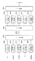
これらを同時に入力し符号化処理する場合のシステム構成例を図2に示す。サウンドオブジェクト符号化器5001、自然画像オブジェクト符号化器5002、合成画像オブジェクト符号化器5003および文字オブジェクト符号化器5004により、オブジェクトはそれぞれ符号化処理される。この符号化と略同時に、シーン内における各オブジェクトの関連を示すシーン構成情報を、シーン記述情報符号化器5005により符号化する。符号化されたオブジェクト情報およびシーン記述情報は、データ多重化器5006によりMPEG4ビットストリームへエンコード処理される。
【0025】
このようにエンコード側では、複数のビジュアルオブジェクトやオーディオオブジェクトの組み合わせを定義して、一つのシーン(画面)を表現する。ビジュアルオブジェクトに関しては、自然画像とコンピュータグラフィクスなどの合成画像とを組み合わせたシーンも構成できる。また、上記のような構成をとることで、例えば、テキスト音声合成の機能を使って、被写体映像とその音声との同期再生が可能になる。なお、前記のビットストリーム状態で送受信または記録再生が行われる。
【0026】
デコード処理は、先のエンコード処理の逆処理である。データ分離器5007により、MPEG4ビットストリームを各オブジェクトに分離し分配する。分離されたサウンド、自然画像、合成画像および文字などのオブジェクトは、対応する復号器5008から5011によりオブジェクトデータへ復号される。また、シーン記述情報も略同時に復号器5012により復号される。これらの復号情報を用いて、シーン合成器5013は、元のシーンを合成する。
【0027】
デコード側では、シーンに含まれるビジュアルオブジェクトの位置や、オーディオオブジェクトの順番など、部分的な変更が可能である。オブジェクト位置はドラッグにより変更でき、言語の変更などはユーザがオーディオオブジェクトを変更することで可能になる。
【0028】
複数のオブジェクトを自由に組み合わせてシーンを合成するために、次の四つの項目が規定されている。
【0029】
●オブジェクト符号化
ビジュアルオブジェクトおよびオーディオオブジェクト、並びに、それらを組み合わせたAV(オーディオビジュアル)オブジェクトを符号化対象とする。
【0030】
●シーン合成
ビジュアルオブジェクト、オーディオオブジェクトおよびAVオブジェクトを所望するシーンに構成するためのシーン構成情報と合成方式とを規定するために、Virtual Reality Modeling Language(VRML)をモディファイした言語を用いる。
【0031】
●多重化と同期
各オブジェクトを多重同期したストリーム(エレメンタリストリーム)の形式などを定める。このストリームをネットワークに流したり、記録装置に格納するときのサービス品質QOS(Quality of Service)も設定可能である。QOSパラメータには、最大伝送速度、誤り率および伝送方式などの伝送路条件や復号能力などが設けられている。
【0032】
●ユーザの操作(インタラクション)
ビジュアルオブジェクトやオーディオオブジェクトを、ユーザ端末側で合成する方式を定義する。MPEG4のユーザ端末は、ネットワークや記録装置から送られてくるデータを、エレメンタリストリームに分離して、各オブジェクトごとに復号する。複数の符号化されたデータから、同時に送られてきたシーン構成情報を基にしてシーンを再構成する。
【0033】
ユーザ操作(編集)を考慮に入れたシステムの構成例を図3に示す。また、ビデオオブジェクトに関するVOP処理回路のエンコーダ側のブロック図を図4に、デコーダ側のブロック図を図5に示す。
【0034】
[VOP(Video Object Plane)]
MPEG4における映像の符号化は、対象の映像オブジェクトを形状(Shape)とその絵柄(Texture)に分けてそれぞれ符号化する。この映像データの単位をVOPという。図6はVOPの符号化および復号の全体構成を示すブロック図である。
【0035】
例えば、画像が人物と背景の二つのオブジェクトから構成されている場合、各フレームを二つのVOPに分割して符号化する。各VOPを構成する情報は、図7Aに示されるように、オブジェクトの形状情報、動き情報およびテキスチャ情報である。一方、復号器は、ビットストリームをVOP毎に分離し個別に復号した後、これらを合成して画像を形成する。
【0036】
このように、VOP構造の導入により、処理対象の画像が複数の映像オブジェクトから構成されている場合、これを複数のVOPに分割し、個別に符号化/復号することができる。なお、VOPの数が1で、オブジェクト形状が矩形の場合は、図7Bに示すように、従来からのフレーム単位の符号化になる。
【0037】
VOPには三種類の予測方式、面内符号化(I-VOP)、前方向予測(P-VOP)および双方向予測(B-VOP)がある。予測単位は16×16画素のマクロブロック(MB)である。
【0038】
双方向予測B-VOPは、MPEG1およびMPEG2のBピクチャと同じく、過去のVOPおよび未来のVOPの両方向からVOPを予測する方式である。そして、マクロブロック単位に直接符号化/前方符号化/後方符号化/双方符号化の四種類のモードが選択可能である。そしてこのモードは、MBまたはブロック単位に切り替えることが可能である。P-VOPの動きベクトルのスケーリングで双方向予測する。
【0039】
[形状(Shape)符号化]
オブジェクト(物体)単位で画像を扱うためには、物体の形状が符号化および復号の際に既知でなければならない。また、後方にある物体が透けて見えるガラスのような物体を表現するためには、物体の透明度を表す情報が必要になる。この物体の形状および物体の透明度の情報を合わせて形状情報と呼ぶ。そして、形状情報の符号化を形状符号化と呼ぶ。
【0040】
[サイズ変換処理]
二値形状符号化は、画素毎に物体の外側にあるのか内側にあるのかを判定して、境界画素を符号化する手法である。従って、符号化すべき画素数が少ないほど発生符号量も少なくて済む。しかし、符号化すべきマクロブロックサイズを小さくすることは、元の形状符号が劣化して受信側に伝送されることになる。従って、サイズ変換により元の情報がどの程度劣化するかを測定し、所定のしきい値以下のサイズ変換誤差が得られる限りは、できるだけ小さなマクロブロックサイズを選択する。具体的なサイズ変換比率としては、原寸大、縦横1/2倍、縦横1/4倍の三種類が挙げられる。
【0041】
各VOPの形状情報は、8ビットのα値として与えられ、次のように定義される。
α = 0: 該当VOPの外側
α = 1〜254: 他のVOPと半透明状態で表示
α = 255: 該当VOPのみの表示領域
【0042】
二値形状符号化は、α値が0あるいは255をとる場合であり、該当VOPの内側と外側のみで形状が表現される。多値形状符号化は、α値が0から255のすべての値を取り得る場合で、複数のVOP同士が半透明で重畳された状態を表現することができる。
【0043】
テキスチャ符号化と同様に16×16画素のブロック単位に一画素精度の動き補償予測をする。オブジェクト全体を面内符号化する場合は形状情報の予測はしない。動きベクトルは、隣接するブロックから予測した動きベクトルの差分を用いる。求めた動きベクトルの差分値は、符号化してからビットストリームに多重化する。MPEG4では、動き補償予測したブロック単位の形状情報を二値形状符号化する。
【0044】
●フェザーリング
その他、二値形状の場合でも、境界部を不透明から透明に滑らかに変化させたい場合はフェザーリング(境界形状のスムージング)を使う。フェザーリングは、境界値を線形に補間する線形フェザーリングモードと、フィルタを使うフェザーリングフィルタモードがある。不透明度が一定な多値形状には、定アルファモードがあり、フェザーリングと組み合わせが可能である。
【0045】
[テキスチャ符号化]
オブジェクトの輝度成分や色差成分の符号化を行うもので、フィールド/フレーム単位のDCT(Discrete Cosine Tranfer)、量子化、予測符号化および可変長符号化の順に処理する。
【0046】
DCTは8×8画素のブロックを処理単位とするが、オブジェクト境界がブロック内にある場合は、オブジェクトの平均値でオブジェクト外の画素を補填する。その後、4タップの二次元フィルタ処理を施すことで、DCT係数に大きな擬似ピークが発生する現象を防ぐ。
【0047】
量子化はITU-T勧告H.263の量子化器あるいはMPEG2の量子化器の何れかを使う。MPEG2量子化器を使えば、直流成分の非線形量子化やAC成分の周波数重み付けが可能になる。
【0048】
量子化後の面内符号化係数は、可変長符号化する前にブロック間で予測符号化し冗長成分を削除する。とくに、MPEG4では直流成分と交流成分の両方に対して予測符号化する。
【0049】
テキスチャ符号化のAC/DC予測符号化は、図8に示すように、注目ブロックに隣接するブロック間で対応する量子化係数の差分(勾配)を調べ、小さい方の量子化係数を予測に使う。例えば、注目ブロックの直流係数xを予測する場合、対応する隣接ブロックの直流係数がa、bおよびcならば次のようになる。
|a - b| < |b - c| ならば直流係数cを予測に使う
|a - b| ≧ |b - c| ならば直流係数aを予測に使う
【0050】
注目ブロックの交流係数Xを予測する場合も、上記と同様に予測に使う係数を選んだ後、各ブロックの量子化スケール値QPで正規化する。
【0051】
直流成分の予測符号化は、隣接するブロック間で上下に隣接するブロックの直流成分の差(垂直勾配)と、左右に隣接するブロックの直流成分の差(水平勾配)を調べ、勾配の少ない方向のブロックの直流成分との差分を予測誤差として符号化する。
【0052】
交流成分の予測符号化は、直流成分の予測符号化に合わせて、隣接ブロックの対応する係数を用いる。ただし、量子化パラメータの値がブロック間で異なっている可能性があるので、正規化(量子化ステップスケーリング)してから差分をとる。予測の有無はマクロブロック単位に選択できる。
【0053】
その後、交流成分は、ジグザグスキャンされ、三次元(Last、RunおよびLevel)可変長符号化される。ここで、Lastはゼロ以外の係数の終りを示す1ビットの値、Runはゼロの継続長、Levelは非ゼロ係数の値である。
【0054】
面内符号化された直流成分の可変長符号化には、直流成分用可変長符号化テーブルまたは交流成分用可変長テーブルの何れかを使う。
【0055】
[動き補償]
MPEG4では任意の形状のビデオオブジェクトプレーン(VOP)を符号化することができる。VOPには、前述したように、予測の種類によって面内符号化(I-VOP)、前方向予測符号化(P-VOP)および双方向予測符号化(B-VOP)があり、予測単位は16ライン×16画素または8ライン×8画素のマクロブロックを使う。従って、VOPの境界上に跨るマクロブロックも存在することになる。このVOP境界の予測効率を改善するために、境界上のマクロブロックに対してはパディング(補填)およびポリゴンマッチング(オブジェクト部分のみのマッチング)を行う。
【0056】
[ウェーブレット符号化]
ウェーブレット(wavelet)変換は、一つの孤立波関数を拡大/縮小/平行移動して得られる複数の関数を変換基底とする変換方式である。このウェーブレット変換を用いた静止画像の符号化モード(Texture Coding Mode)は、とくにコンピュータグラフィックス(CG)画像と自然画像とが合成された画像を扱う場合に、高解像度から低解像度までの様々な空間解像度を備えた高画質の符号化方式として適している。ウェーブレット符号化は、画像をブロック分割せず一括して符号化することができるため、低ビットレートでもブロック歪みが発生せず、モスキート雑音も減少できる。このように、MPEG4の静止画像符号化モードは、低解像度かつ低画質の画像から高解像度かつ高画質の画像までの幅広いスケーラビリティ、処理の複雑性および符号化効率のトレードオフの関係をアプリケーションに応じて調整できる。
【0057】
[階層符号化(スケーラビリティ)]
スケーラビリティを実現するために、図9Aおよび9Bに示すようなシンタックスの階層構造を構成する。階層符号化は、例えばベースレイヤを下位レイヤ、補強レイヤを上位レイヤとし、補強レイヤにおいてベースレイヤの画質を向上する「差分情報」を符号化することによって実現される。空間スケーラビリティの場合、ベースレイヤは低解像度の動画像を、「ベースレイヤ+補強レイヤ」で高解像度の動画像を表す。
【0058】
さらに、画像全体の画質を階層的に向上させるほかに、画像中の物体領域のみ画質を向上させる機能がある。例えば、時間スケーラビリティの場合、ベースレイヤは画像全体を低いフレームレートで符号化したもの、補強レイヤは画像内の特定オブジェクトのフレームレートを向上させるデータを符号化したものになる。
【0059】
●時間スケーラビリティ
図9Aに示す時間スケーラビリティは、フレーム速度を階層化し、補強レイヤのオブジェクトのフレーム速度を速くすることができる。階層化の有無はオブジェクト単位で設定できる。補強レイヤのタイプは二つで、タイプ1はベースレイヤのオブジェクトの一部で構成する。タイプ2はベースレイヤと同じオブジェクトで構成する。
【0060】
●空間スケーラビリティ
図9Bに示す空間スケーラビリティは空間解像度を階層化する。ベースレイヤは、任意のサイズのダウンサンプリングが可能で、補強レイヤの予測に使用される。
【0061】
[スプライト符号化]
スプライトとは、三次元空間画像における背景画像などのように、オブジェクト全体が統一的に移動、回転、変形などを表現できる平面的なオブジェクトのことである。この平面的オブジェクトを符号化する手法をスプライト符号化と呼ぶ。
【0062】
スプライト符号化は四種、静的/動的およびオンライン/オフラインに区別される。詳しく説明すると、オブジェクトデータを予め復号器に送り、グローバル動き係数だけをリアルタイムに伝送する構成であって、テンプレートオブジェクトの直接変換で得られる静的スプライト。時間的に前のスプライトからの予測符号化により得られる動的スプライト。事前に面内符号化(I-VOP)により符号化され、復号器側に伝送されるオフラインスプライト。符号化中に符号化器および復号器で同時に作成されるオンラインスプライトがある。
【0063】
スプライト符号化に関して検討されている技術には、スタティックスプライト(Static Sprite)符号化、ダイナミックスプライト(Dynamic Sprite)符号化、グローバル動き補償などがある。
【0064】
●スタティックスプライト符号化
スタティックスプライト符号化は、ビデオクリップ全体の背景(スプライト)を予め符号化しておき、背景の一部を幾何変換することによって画像を表現する方法である。切り出された一部の画像は、平行移動、拡大/縮小、回転など様々な変形を表現することができる。これについて図10Aに示すように、画像の移動、回転、拡大/縮小、変形などにより三次元空間における視点移動を表現することをワープと呼ぶ。
【0065】
ワープの種類には遠近法変換、アフィン変換、等方拡大(a)/回転(θ)/移動(c, f)および平行移動があり、図10Bの各式で表される。図10Bに示す式の係数によって移動、回転、拡大/縮小、変形などが表される。また、スプライトの生成は符号化開始前にオフラインで行われる。
【0066】
このように、背景画像の一部領域を切り取り、この領域をワープして表現することでスタティックスプライト符号化は実現される。図11に示すスプライト(背景)画像に含まれる一部領域がワープされることになる。例えば、背景画像はテニスの試合における観客席などの画像であり、ワープされる領域はテニスプレーヤなどの動きのあるオブジェクトを含んだ画像である。また、スタティックスプライト符号化においては、幾何変換パラメータのみを符号化して、予測誤差を符号化しない。
【0067】
●ダイナミックスプライト符号化
スタティックスプライト符号化では符号化前にスプライトが生成される。これに対して、ダイナミックスプライト符号化では、符号化しながらオンラインにスプライトを更新することができる。また、予測誤差を符号化するという点でスタティックスプライト符号化とは異なる。
【0068】
●グローバル動き補償(GMC)
グローバル動き補償とは、オブジェクト全体の動きを、ブロックに分割することなく、一つの動きベクトルで表して動き補償する技術であり、剛体の動き補償などに適している。参照画像が、スプライトの代わりに直前の復号画像になる点、予測誤差を符号化する点では、スタティックスプライト符号化と同様である。ただし、スプライトを格納するためのメモリを必要としないこと、形状情報が不要であることは、スタティックスプライト符号化およびダイナミックスプライト符号化とは異なる。画面全体の動きや、ズームを含む画像などにおいて効果がある。
【0069】
[シーン構造記述情報]
シーン構成情報によりオブジェクトは合成される。MPEG4では、各オブジェクトをシーンに合成するための構成情報を伝送する。個別に符号化された各オブジェクトを受信したときに、シーン構成情報を使えば、送信側が意図したとおりのシーンに合成できる。
【0070】
シーン構成情報には、オブジェクトの表示時間や表示位置などが含まれ、これらがツリー状のノード情報として記述されている。各ノードは、親ノードに対する時間軸上の相対時刻情報と相対空間座標位置情報をもつ。シーン構成情報を記述する言語には、VRMLを修正したBIFS(Binary Format for Scenes)とJava(TM)を用いたAAVS(Adaptive Audio-Visual Session Format)がある。BIFSは、MPEG4のシーン構成情報を二値で記述する形式。AAVSはJava(TM)をベースとし、自由度が大きくBIFSを補う位置付けにある。図12はシーン記述情報の構成例を示す図である。
【0071】
[シーン記述]
シーン記述はBIFSによって行われる。ここでは、VRMLとBIFS共通の概念であるシーングラフとノードを中心に説明する。
【0072】
ノードは光源、形状、材質、色および座標などの属性や、座標変換を伴う下位ノードのグループ化を指定する。オブジェクト指向の考えを取り入れ、三次元空間中の各物体の配置やみえ方は、シーングラフと呼ばれる木を、頂点のノードから辿り、上位ノードの属性を継承することにより決定される。葉にあたるノードにメディアオブジェクト、例えば、MPEG4ビデオのビットストリームを同期をとって割当てれば、他のグラフィクスと伴に動画を三次元空間内に合成して表示することができる。
【0073】
また、VRMLとの差異は下記のとおりである。MPEG4システムでは次をBIFSでサポートする。
(1)MPEG4ビデオVOP符号化の二次元オーバラップ関係記述と、MPEG4オーディオの合成記述
(2)連続メディアストリームの同期処理
(3)オブジェクトの動的振る舞い表現(例えばスプライト)
(4)伝送形式(バイナリ)を標準化
(5)セッション中にシーン記述を動的に変更
【0074】
VRMLのノードのうちExtrusion、Script、ProtoおよびExtemProtoなどがサポートされていない以外は、VRMLノードのほぼすべてがBIFSでサポートされている。BIFSで新たに加えられたMPEG4特別ノードには、以下のものがある。
(1)2D/3D合成のためのノード
(2)2Dグラフィクスやテクストのためのノード
(3)アニメーションノード
(4)オーディオノード
【0075】
特筆すべきは、VRMLでは背景など特殊なノードを除き2D合成はサポートされていなかったが、BIFSでは、テキストやグラフィックオーバレイ、さらにMPEG4ビデオVOP符号化を画素単位で扱えるように記述が拡張されている。
【0076】
アニメーションノードには、3Dメッシュで構成された顔などMPEG4のCG画像のための特別なノードが規定されている。シーングラフ中のノードの置き換え、消去、追加および属性変更が動的に行えるメッセージ(BIFS Update)があり、セッションの途中で画面上に新たな動画像を表示したり、ボタンを追加することが可能になる。BIFSは、VRMLの予約語、ノード識別子および属性値をほぼ一対一にバイナリデータに置き換えることにより実現できる。
【0077】
[MPEG4オーディオ]
図13にMPEG4オーディオの符号化方式の種類を示す。オーディオおよびサウンドの符号化には、パラメトリック符号化、CELP(Code Excited Linear Prediction)符号化、時間/周波数変換符号化が含まれる。さらに、SNHC(Synthetic Natural Hybrid Coding)オーディオの機能も取り入れ、SA(Structured Audio: 構造化オーディオ)符号化とTTS(Text to Speech: テキストサウンド合成)符号化が含まれる。SAはMIDI(Music Instrument Degital Interface)を含む合成楽音の構造的記述言語であり、TTSは外部のテキスト音声合成装置にイントネーションや音韻情報などを送るプロトコルである。
【0078】
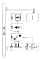
図14にオーディオ符号化方式の構成を示す。図14において、入力サウンド信号を前処理(201)し、パラメトリック符号化(204)、CELP符号化(205)および時間/周波数符号化(206)の三つの符号化を使い分けるように、帯域に応じて信号分割(202)し、それぞれに適した符号化器へ入力する。また、信号分析制御(203)により、入力オーディオ信号が分析され、入力オーディオ信号を各符号化器へ割り当てるための制御情報などが発生される。
【0079】
続いて、それぞれ別の符号化器であるパラメトリック符号化コア(204)、CELP符号化コア(205)、時間/周波数変換符号化コア(206)は、各符号化方式に基づいた符号化処理を実行する。これら三種の符号化方式については後述する。パラメトリック符号化およびCELP符号化されたオーディオデータは、小ステップ強化(207)され、時間/周波数変換符号化および小ステップ強化されたオーディオデータは、大ステップ強化(208)される。なお、小ステップ強化(207)および大ステップ強化(208)は、各符号化処理で発生する歪を減少させるためのツールである。こうして、大ステップ強化されたオーディオデータは、符号化されたサウンドビットストリームになる。
【0080】
以上が図75のサウンド符号化方式の構成の説明であるが、次に、図13を参照しながら各符号化方式について説明する。
【0081】
●パラメトリック符号化
音声信号や楽音信号を含むサウンド信号を周波数、振幅およびピッチなどのパラメータで表現し、それを符号化する。音声信号用の調波ベクトル駆動符号化(HVXC: Harmonic Vector Excitation Coding)と、楽音信号用の個別スペクトル(IL: Individual Line)符号化が含まれる。
【0082】
HVXC符号化は、主として2k〜4kbpsの音声符号化を目的とし、音声信号を有声音と無声音に分類し、有声音は線形予測係数(LPC: Linear Prediction Coefficient)の残差信号の調波(ハーモニック)構造をベクトル量子化する。無声音については、予測残差をそのままベクトル駆動符号化(vector excitation coding)する。
【0083】
IL符号化は、6k〜16kbpsの楽音の符号化を目的としており、信号を線スペクトルでモデル化して符号化するものである。
【0084】
●CELP符号化
入力サウンド信号をスペクトル包絡情報と音源情報(予測誤差)とに分離して符号化する方式である。スペクトル包絡情報は、入力サウンド信号から線形予測分析によって算出される線形予測係数によって表される。MPEG4のCELP符号化には帯域幅4kHzの狭帯域CELPと、帯域幅8kHzの広帯域CELPがあり、狭帯域(NB: Narrow Band) CELPは3.85〜12.2kbps、広帯域(WB: Wide Band) CELPは13.7k〜24kbpsの間においてビットレートの選択が可能である。
【0085】
●時間/周波数変換符号化
高音質を目指す符号化方式である。AAC(Advanced Audio Coding)に準拠する方式、およびTwinVQ(Transform-domain Weighted Interleave Vector Quantization: 変換領域重み付けインタリーブベクトル量子化)がこれに含まれる。この時間/周波数変換符号化には聴覚心理モデルが組み込まれ、聴覚マスキング効果を利用しながら適応量子化する仕組みになっている。
【0086】
AAC準拠方式は、オーディオ信号をDCTなどで周波数変換し、聴覚マスキング効果を利用しながら適応量子化する仕組みである。適応ビットレートは24k〜64kbpsである。
【0087】
TwinVQ方式は、オーディオ信号を線形予測分析したスペクトル包絡を用いて、オーディオ信号のMDCT係数を平坦化する。インタリーブを施した後、二つの符号長を用いてベクトル量子化する仕組みである。適応ビットレートは6k〜40kbpsである。
【0088】
[システム構造]
MPEG4のシステムパートでは、多重化、分離および合成(コンポジション)を定義する。以下、図15を用いてシステム構造を説明する。
【0089】
多重化においては、映像符号化器やオーディオ符号化器からの出力である各オブジェクトや、各オブジェクトの時空間配置を記述したシーン構成情報などのエレメンタリストリームごとに、アクセスユニットレイヤでパケット化される。アクセスユニットレイヤでは、アクセスユニット単位に同期を取るためのタイムスタンプや参照クロックなどがヘッダとして付加される。パケット化されたストリームは、次に、FlexMuxレイヤで表示や誤り耐性の単位で多重化され、TransMuxレイヤへ送られる。
【0090】
TransMuxレイヤでは、誤り耐性の必要度に応じて誤り訂正符号が保護サブレイヤで付加される。最後に、多重サブレイヤ(Mux Sub Layer)で一本のTransMuxストリームとして伝送路に送り出される。TransMuxレイヤは、MPEG4では定義されず、インターネットのプロトコルであるUDP/IP(User Datagram Protocol/Internet Protocol)やMPEG2のトランスポートストリーム(TS)、ATM(Asynchronous Transfer Mode)のAAL2(ATM Adaptation layer2)、電話回線利用のテレビ電話用多重化方式(ITU-T勧告H.223)、および、ディジタルオーディオ放送などの既存のネットワークプロトコルが利用可能である。
【0091】
システムレイヤのオーバヘッドを軽くし、従来のトランスポートストリームに容易に埋め込めるように、アクセスユニットレイヤやFlexMuxレイヤをバイパスすることも可能である。
【0092】
復号側では、各オブジェクトの同期を取るために、デマルチプレクス(分離)の後段にバッファ(DB: Decoding Buffer)を設け、各オブジェクトの到達時刻や復号時間のずれを吸収する。合成の前にもバッファ(CB: Composition Buffer)を設けて表示タイミングを調整する。
【0093】
[ビデオストリームの基本構造]
図16にレイヤ構造を示す。各階層をクラスと呼び、各クラスにはヘッダが付く。ヘッダとはstart code、end code、ID、形状およびサイズほかの各種符号情報である。
【0094】
●ビデオストリーム
ビデオストリームは複数のセッションで構成される。セッションとは、一連の完結したシーケンスのことである。
VS: セッションは複数のオブジェクトで構成される
VO: ビデオオブジェクト
VOL: オブジェクトは複数のレイヤを含むオブジェクト単位のシーケンス
GOV: オブジェクトは複数のレイヤで構成される
VOP: オブジェクトレイヤは複数のプレーンで構成される
ただし、プレーンはフレーム毎のオブジェクト
【0095】
[誤り耐性を有するビットストリーム構造]
MPEG4は、移動体通信(無線通信)などに対応すべく、符号化方式自体が伝送誤りに対する耐性を有している。既存の標準方式における誤り訂正は主にシステム側で行っているが、PHS(Personal Handy phone System)などのネットワークでは誤り率が非常に高く、システム側では訂正しきれない誤りがビデオ符号化部分に漏れ込んでくることが予想される。これを考慮して、MPEG4は、システム側で訂正しきれなかった各種のエラーパターンを想定し、このような環境の下でも可能な限り誤りの伝播が抑制されるような誤り耐性符号化方式とされている。ここでは、画像符号化に関する誤り耐性の具体的な手法と、そのためのビットストリーム構造を説明する。
【0096】
●Reversible VLC(RVLC)と双方向復号
図17に示すように、復号途中で誤りの混入が確認された場合、そこで復号処理を一旦停止し、次の同期信号の検出を行う。次の同期信号が検出できた段階で、今度はそこから逆向きにビットストリームの復号処理を行う。新たな付加情報なしに、復号のスタートポイントが増加していることになり、誤り発生時に復号できる情報量を従来よりも増やすことが可能になる。このような順方向と同時に逆方向からも復号可能な可変長符号により「双方向復号」が実現される。
【0097】
●重要情報の複数回伝送
図18に示すように、重要情報を複数回伝送することが可能な構成を導入し、誤り耐性を強化する。例えば、各VOPを正しいタイミングで表示するためにはタイムスタンプが必要であり、この情報は最初のビデオパケットに含まれている。仮に、誤りによってこのビデオパケットが消失しても、前記の双方向復号構造により次のビデオパケットから復号が再開できるが、このビデオパケットにはタイムスタンプがないため、結局、表示タイミングがわからないことになる。そのため各ビデオパケットにHEC(Header Extension Code)というフラグを立て、この後にタイムスタンプなどの重要情報を付加できる構造が導入された。HECフラグの後には、タイムスタンプとVOPの符号化モードタイプとが付加できる。
【0098】
同期はずれが生じた場合は、次の同期回復マーカ(RM)から復号が開始されるが、各ビデオパケットにはそのために必要な情報、そのパケットに含まれる最初のMBの番号およびそのMBに対する量子化ステップサイズがRM直後に配置されている。その後にHECフラグが挿入され、HEC=‘1’の場合にはTRおよびVCTがその直後に付加される。これらHEC情報により、仮に、先頭のビデオパケットが復号できずに廃棄されても、HEC=‘1’と設定したビデオパケット以降の復号および表示は正しく行われることになる。なお、HECを‘1’にするか否かは符号化側で自由に設定できる。
【0099】
●データパーティショニング
符号化側では、MB単位の符号化処理を繰り返してビットストリームを構成するため、途中に誤りが混入すると、それ以降のMBデータは復号できない。一方、複数のMB情報をまとめて幾つかのグループに分類し、それぞれをビットストリーム内に配置し、各グループの境目にマーカ情報を組み込めば、仮にビットストリームに誤りが混入してそれ以降のデータが復号できない場合でも、そのグループの最後にあるマーカで同期を取り直して、次のグループのデータを正しく復号することが可能になる。
【0100】
以上の考えに基づき、ビデオパケット単位に、動きベクトルとテクスチャ情報(DCT係数など)とにグループ分けするデータパーティショニング手法(Data Partitioning)が採用されている。また、グループの境目にはモーションマーカ(MM:
Motion Marker)が配置される。
【0101】
仮に、動きベクトル情報の途中に誤りが混入していても、MMの後にくるDCT係数は正しく復号できるため、誤り混入以前の動きベクトルに対応するMBデータはDCT係数とともに正確に再生できる。またTexture部分に誤りが混入した場合でも、動きベクトルが正しく復号されていれば、その動きベクトル情報と復号済みの前フレーム情報とを用いて、ある程度正確な画像が補間再生(コンシールメント)できる。
【0102】
●可変長間隔同期方式
ここでは、可変長パケットで構成されている同期回復手法を説明する。先頭に同期信号を含んだMB群は「ビデオパケット」と呼ばれ、その中に何個のMBを含めるかは符号化側で自由に設定することができる。可変長符号(VLC: Variable Length Code)を使用するビットストリームに誤りが混入した場合、それ以降の符号の同期が取れなくなり、復号不可能な状態になる。このような場合でも、次の同期回復マーカを検出することにより、その後の情報を正しく復号することが可能になる。
【0103】
[バイトアライメント]
システムとの整合性をとるために、情報の多重化はバイトの整数倍単位で行われる。ビットストリームは、バイトアラインメント(Byte alignment)構造となっている。バイトアラインメントを行うために、各ビデオパケットの最後にスタッフビットが挿入される。さらにこのスタッフビットは、ビデオパケット内のエラーチェック符号としても使用される。
【0104】
スタッフビットは‘01111’のように、最初の1ビットが‘0’で、それ以外のビットがすべて‘1’であるような符号で構成されている。つまりビデオパケット内の最後のMBまで正しく復号されれば、その次に来る符号は必ず‘0’であり、その後にはスタッフビットの長さより1ビット分だけ短い‘1’の連続があるはずである。もし、このルールに反したパターンが検出された場合、それ以前の復号が正しく行われていないことになり、ビットストリームに誤りが混入していたことが検出できる。
【0105】
以上、「国際標準規格MPEG4の概要決まる」(日経エレクトロニス 1997.9.22号 p.147-168)、「見えてきたMPEG4の全貌」(社団法人映像情報メディア学会テキスト 1997.10.2)、「MPEG4の最新標準化動向と画像圧縮技術」(日本工業技術センター セミナー資料 1997.2.3)などを参考にして、MPEG4の技術に関して説明した。
【0106】
【第1実施形態】
[構成]
以下、本発明にかかる一実施形態のテレビ放送受信装置を図面を参照して詳細に説明する。図19は本発明にかかる実施形態のテレビ放送受信装置の構成例を示すブロック図である。
【0107】
ディジタルテレビ放送の信号は、その放送形態に応じて、衛星放送のときは衛星アンテナ21およびチューナ23により、ケーブル放送のときはケーブル22を介してチューナ24により、選局され受信される。こうして衛星放送もしくはケーブル放送から受信されたテレビ情報は、データ選択器43により一方のデータ列が選択され、復調回路25で復調され、誤り訂正回路26で誤り訂正される。
【0108】
続いて、テレビ情報は、多重データ分離回路27により多重されている各データ、つまり画像データ、サウンドデータおよびその他のシステムデータ(追加データ)に分離される。このうち、サウンドデータは、サウンド復号回路28で復号され、ステレオオーディオデータA(L),A(R)になり、サウンド制御部30により音量や音場定位の調整および主/副音声などサウンド多重への対応が処理された後、出力するサウンドが選択され、ディジタル-アナログコンバータ(D/A)29によりアナログ信号に変換されて、スピーカ31により再生される。
【0109】
一方、画像データは、画像データ中の各オブジェクトにそれぞれに対応して復号処理を行う複数の復号器からなる画像復号回路32で復号される。この復号方式は、既に説明したMPEG4の画像復号方式に基づくオブジェクト単位の復号である。復号された画像データは、オブジェクトの数に相当する画像v(1)からv(i)になり、表示制御部34により表示に基づく様々な処理が施される。
【0110】
表示制御部34が行う表示制御とは、各オブジェクトを合成して一つの出力画像としたり、各オブジェクトを表示するか否か、各オブジェクトの拡大/縮小、どこに表示するかなどを行う。さらに、表示制御は、オブジェクトとキャラクタ発生回路40で発生されたキャラクタ画像(時間表示やインデックスタイトルなど)との合成などの各種表示処理も行う。これらの表示制御は、各オブジェクトの配置情報、すなわちシーン記述データ変換回路39からのシーン記述情報に基づき、システムコントローラ38の制御に応じて行われるものである。
【0111】
形成された表示画像は、D/A33でアナログ化されCRT35に表示されるか、もしくは、ディジタル信号のまま液晶ディスプレイ(LCD)44などに送られて表示される。
【0112】
他方、システムデータ(シーン記述データや追加データを含む)はシステムデータ復号回路36で復号される。復号されたシステムデータの中からは、カテゴリ情報検出部37により番組に付加されたカテゴリ情報が検出される。検出されたカテゴリ情報は、システムコントローラ38へ入力され、レイアウト設定におけるコマンド発生の基準になる。また、復号されたシステムデータの中から、シーン記述に関するデータがシーン記述データ変換部39に入力される。その他のシステムデータ(オブジェクトの内容をコマンドで表すオブジェクト情報はここに含まれる)は、システムコントローラ38に各種コマンドとして入力される。なお、追加データには、番組のタイトルインデックスなど、ドキュメントなども含まれていてもよい。
【0113】
オブジェクト情報は、各テレビ局が共通に用いるコマンドセットにより、各オブジェクトにタイトル的に割当てられる。受信時、オブジェクト情報を解析することで、オブジェクトの内容を判別し分類することができる。本実施形態では、このオブジェクト情報を利用して、指定されたオブジェクト情報をもつオブジェクトを設定された位置に配置する、レイアウト設定機能を実現する。
【0114】
シーン記述データ変換部39で構成されたシーン記述データを用いて、表示制御部34における各オブジェクトの配置や合成、サウンド制御部30における音量や音場定位などの設定が行われる。また、システムコントローラ38の制御に基づき、シーン記述データ変換部39を調整し、表示制御部34を制御することで、基本レイアウトとは異なる配置にオブジェクトをレイアウトする、つまりレイアウトが設定された場合の配置制御を行うことができる。このレイアウト設定方法については後述する。
【0115】
また、オブジェクトとしては扱われていない表示画像、例えば時間表示画面やタイトルインデックスなどを生成するときは、キャラクタ発生回路40が用いられる。システムコントローラ38の制御により、追加データに含まれる時間データもしくは受信機内部で生成された時間情報などから、キャラクタデータが保存されているROMなどのメモリ42を用いて、時間表示キャラクタが生成される。タイトルインデックスも同様である。ここで生成された画像は、表示制御部34において合成などが行われる。
【0116】
また、ユーザは指示入力部45を介して各種コマンドを入力することができる。ユーザの指示入力に基づき、レイアウト設定処理における位置調整を行うことができる。すなわち、レイアウト位置の補正や、新規設定値の入力は指示入力部45から行われる。指示入力値に応じてシステムコントローラ38は、所望の出力(表示、再生)形態が得られるように各部の動作を適切に制御する。
【0117】
[レイアウトの設定]
カテゴリ情報を判別して、カテゴリ毎にオブジェクトを所定配置するレイアウト設定は、二つの方法で実行することができる。第一の方法は、予めプログラムされたデフォルト設定としてメモリ41に工場出荷時から保持されているレイアウト設定データを用いてレイアウト設定する方法であり、第二の方法は、ユーザが任意に設定したレイアウトのレイアウト設定データをメモリ41にカテゴリ毎に保持しておいて、これを利用するものである。
【0118】
ここで、具体的なレイアウトの設定方法を説明する。図20はレイアウト設定する際の位置データの設定方法を説明する図、図21はレイアウト設定する際のイメージと指示の入力方法とを説明する図である。
【0119】
オブジェクトの位置設定には二つ方法がある。第一の方法はシーン記述データで規定される基本レイアウトを位置補正(シフト)する方法であり、第二の方法はユーザが任意の場所にオブジェクトの位置を新規に設定する方法である。両者は、ユーザの操作に応じて、図20に示すセレクタ302で選択可能である。
【0120】
まず、第一の方法であるシフトする方法について説明する。オブジェクトとして画像データが入力され、そのオブジェクトの基本位置はシーン記述データで指定される位置データ(X0,Y0)で表される。ユーザがオブジェクトのシフトを望む場合、加算器301により補正量(ΔX,ΔY)が位置データ(X0,Y0)に加算され、新たな位置データ(X',Y')がオブジェクトのレイアウト設定データになる。第二の方法である新規設定する方法について説明する。基本位置データに関係なく、全く新たにオブジェクトの位置(X,Y)を設定し、これを基本位置データに代わる位置データ(X',Y')にする。このようにして、ユーザが設定したレイアウト設定用の位置データを、シーン記述データで規定される基本レイアウトのオブジェクト位置データに置き換えて、表示する。
【0121】
以上が指定画像オブジェクトのレイアウトを設定する方法の説明である。対象となるオブジェクトを判別するオブジェクト情報もレイアウト設定データの一部として必要なデータである。表示処理はシステムコントローラ38により制御されるが、このときの制御データ、対象オブジェクトを判別するためのオブジェクト情報およびレイアウト設定データを、カテゴリに対応させたユーザレイアウト設定データとしてメモリ41に保持しておく。
【0122】
次に図12について説明する。図12はこれまでに説明した位置の設定方法を図示したものである。CRTなどの表示装置303において、操作の対象になる基本位置にあるオブジェクト306(位置は(X0,Y0))を、シフト位置307までシフトしたとき、その時の補正量を基本位置データに加えて、最終的な位置データ(レイアウト設定データ)は、(X’,Y’)=(X0+ΔX,Y0+ΔY)になる。また、ユーザが任意で新規に新規設定位置308にオブジェクトを配置した場合は、その位置データ(レイアウト設定データ)は(X’,Y’)=(X,Y)になる。図11で説明した、設定方法は、このように図示される。
【0123】
また、図21には指示入力部45に含まれるポインティングデバイスの一例としてマウス304およびリモートコントローラ305を示す。マウス304を使ったり、リモートコントローラ305の方向入力キー(十字キー、ジョイスティックおよびジョイパッドなどでもよい)を使うことによって、自由なオブジェクトの移動を容易に操作することが可能である。なお、オブジェクトを移動する位置および新たに設定する位置は、画面の四隅や中央などプリセットされた幾つかの位置から選ぶような構成をとることもできる。
【0124】
テレビ放送データの中にはカテゴリ情報が含まれている。このカテゴリ情報を利用することで、各番組毎に、設定されたレイアウトをカテゴリ情報と対応付けてデータ化し、レイアウト設定データとして記憶しておくことができる。この記憶場所は、EEPROMなどの不揮発性メモリ41が利用される。システムコントローラ38は、テレビ放送データからメモリ41に記憶されているカテゴリ情報が検出されると、そのカテゴリ情報に対応するレイアウト設定データを基に、シーン記述データ変換部39および表示制御部34を制御し、設定されたレイアウトで画像表示およびサウンド再生を行う。
【0125】
続いて、レイアウト設定データについて説明する。レイアウト設定データには、予めプログラムされ保持されているデフォルトの設定データ、および、ユーザが設定したデータがある。ユーザ設定データは、基本的には、シーン記述データから得られるオブジェクト配置情報を基にして、オブジェクト配置情報に加え、ユーザがレイアウト設定したときのオブジェクトの位置をデータ化して、各部の制御データおよび対象となるオブジェクト情報とともに、レイアウト設定データとして記憶すればよい。シーン記述データについては図12を用いて既に説明したが、各シーンを構成するオブジェクトをツリー型に配列し、それぞれのオブジェクトが表示されるべき時間や、表示されるべき位置を指定するための情報である。
【0126】
また、その他のレイアウト設定データの構成として、図22に示すように、そのオブジェクトを表示するか否かを示すオン/オフデータ、表示位置をXおよびY軸で二次元表現したときの表示位置データ、並びに、大きさを示すデータを保持することによって、対象となるオブジェクトのレイアウト設定データとして活用することができる。
【0127】
図23は一般的なMPEG4ビットストリームの構成を示す図である。図23のオブジェクト1から5までのデータベースに番組内容、(番組に応じてオブジェクトの種類は異なるが)自然画像オブジェクト、サウンドオブジェクトおよびCGなどのオブジェクトが組み込まれている。一例として、野球の中継放送では、背景オブジェクト(スプライト)、人物、その他の自然画像オブジェクト、得点表示の合成画像オブジェクトおよびサウンドオブジェクトなどが該当する。加えて、ビットストリームにはシステムデータとして、シーン記述情報および追加データが多重化されている。追加データには、カテゴリ情報やオブジェクト情報も含まれる。
【0128】
図24および図25は野球の中継放送における画面設定例を示す図、図26および図27は野球の中継放送の表示例を示す図である。
【0129】
野球の中継放送において、レイアウトを設定するオブジェクトとして、図24および図26に示す得点表示オブジェクト310およびカウント表示オブジェクト311があり、図25および図27に示す打率表示オブジェクト312があるとする。上記三つのオブジェクトは野球の中継放送において欠かせないものであるが、それらの表示位置は放送局によって様々であるから、本実施形態によりレイアウトを設定する上で好適なオブジェクトである。これらのオブジェクトはCGなどによる合成画像オブジェクトであるが、本実施形態はオブジェクトの種類は問わない。
【0130】
レイアウト設定モードに移行後、ユーザは画面をみながら、上述した方法によりテレビ画面上の任意の位置、すなわち好みの位置や、みやすい位置へオブジェクトを配置すればよい。
【0131】
このように、本実施形態のレイアウト設定機能を用いることで、図24から図27に示す野球の中継放送の1シーンのように、デフォルト設定またはユーザ設定された位置に、そのオブジェクトを表示するタイミング(シーン)毎に、得点表示オブジェクト310、カウント表示オブジェクト311および打率表示オブジェクト312を表示することができる。このレイアウト表示は放送局を問わず同じレイアウトになる。
【0132】
一度設定されたレイアウト設定データが保持された後は、同一のカテゴリ情報を検出することでレイアウト設定機能が作動し、オブジェクト情報から対象のオブジェクトであるか否かを判別する。対象オブジェクトの場合は、その表示タイミング(シーン)において、保持されているレイアウト設定データに基づく位置へ自動的にレイアウト表示される。なお、放送局毎に、オブジェクト情報のデータ構成が異なる場合は、オブジェクト情報を再設定するようにしてもよい。
【0133】
[動作手順]
図28および図29は本実施形態のテレビ放送受信装置の動作手順例を説明するフローチャートで、図28はユーザがレイアウトを設定する際のフローを、図29はテレビ映像の表示におけるフローである。
【0134】
図28に示すレイアウト設定モードにおいて、テレビ情報中の画像データを構成する各オブジェクトの内、レイアウトを設定するオブジェクトが選択される(ステップS1)。そして、ユーザは、選択(指定)したオブジェクトを任意位置に配置する(ステップS2)。選択されたオブジェクトの配置が完了すると、レイアウト設定を終了するか否かが判断され(ステップS3)、他のオブジェクトについてもレイアウトを設定する場合はステップS1へ戻り、オブジェクトの選択および配置を繰り返す。レイアウト設定が終了ならば、レイアウトが設定された各オブジェクトの位置がデータ化される。そして、そのオブジェクトのカテゴリ情報、オブジェクト情報、位置データおよび各部の制御データが統合され、レイアウト設定データとしてメモリ41に格納される(ステップS4)。
【0135】
図29に示す表示モードにおいて、テレビ情報を受信し(ステップS11)、テレビ情報に付加されたシステムデータから番組のカテゴリ情報を検出する(ステップS12)。カテゴリ情報は、各放送局が統一したコマンドセットなどを用いて、番組のカテゴリ(ジャンル)に対応する情報をシステムデータに付加して送信するものであり、番組の内容を大別させるためのデータである。仮に、放送局毎に番組カテゴリ情報が異なる場合は、放送局間の整合性を取るための再設定手段を設けてもよい。
【0136】
続いて、検出されたカテゴリ情報に対応するレイアウト設定データが既に保存されているか否かが判断される(ステップS13)。レイアウト設定データが保存されていないカテゴリの場合は、放送局から送られてくるそのままの基本レイアウトでテレビ放送の映像を表示する(ステップS14)。
【0137】
レイアウト設定データが保存されたカテゴリの場合は、メモリ41から検出されたカテゴリ情報に対応するレイアウト設定データを読み出し(ステップS15)、そのレイアウト設定データに記録されているオブジェクト情報が出現したら、その対象オブジェクトのレイアウトを変更する制御が行えるようにスタンバイする。従って、ステップS16では、レイアウト設定の対象外のオブジェクトは基本レイアウトで表示され、レイアウト設定の対象オブジェクトは、その対象オブジェクトの表示タイミング(シーン)において、設定されたレイアウトで表示される。
【0138】
番組が終了したり、別のチャネルに移行して新たな番組の受信が開始されるまでは、ステップS14またはステップS16の表示状態が維持される。新たな番組の受信が開始された場合は、現行のレイアウト設定がリセットされ、フローはステップS11のテレビ放送受信の初期状態から繰り返される。
【0139】
本実施形態では、番組のカテゴリとして『野球中継放送』を取り上げたが、これに限らず、『サッカー中継放送』やスポーツ以外の番組のカテゴリであっても同様に対応することができる。
【0140】
このように、本実施形態によれば、ディジタルテレビ放送を視聴するユーザは、番組のカテゴリ情報に対応してオブジェクトのレイアウトを任意に設定することができる。従って、番組のカテゴリおよびユーザの好みに応じた映像表示が可能になり、視覚的および聴覚的ユーザインタフェイスの質的向上を期待することができ、ユーザに対してより自由度のあるテレビ番組表示が可能になる。
【0141】
また、オブジェクトの内容を示すオブジェクト情報を参照して、番組のカテゴリ情報毎にレイアウト設定する場合、オブジェクトの分類および配置制御を行うことにより、指定するオブジェクトのみのレイアウト設定が可能になる。
【0142】
また、同一の番組カテゴリであっても、放送局によって異なるレイアウトで表示される欠点を解消することができ、放送局に関係なく番組カテゴリ毎に統一されたレイアウトで共通するオブジェクトを表示することができる。
【0143】
【第2実施形態】
以下、本発明にかかる第2実施形態のテレビ放送受信装置を説明する。なお、本実施形態において、第1実施形態と略同様の構成については、同一符号を付して、その詳細説明を省略する。
【0144】
第2実施形態においては、MPEG4以外の符号化方式で符号化された画像をMPEG4の一つオブジェクトとして利用、代用したテレビ放送におけるオブジェクトのレイアウト設定について説明する。
【0145】
ここでは、自然画像符号化方式にMPEG2を用いた例を説明する。つまり、MPEG2で符号化された画像(以下「MPEG2画像」と呼ぶ場合がある)がMPEG4のビットストリームに多重化されて伝送され、これを受信して表示するテレビ放送受信装置に関する説明を行う。なお、第2実施形態におけるレイアウトの設定方法は、第1実施形態で説明したものと同様であり、テレビ放送受信装置の基本構成および動作は図19により説明したものと同様である。ただし、第2実施形態におけるテレビ放送の復号方法に関係して、図19に示すサウンド復号回路28、画像復号回路32およびシステムデータ復号回路36の細部が異なるので、これらを図30および図31を用いて説明する。
【0146】
図30は、送信側である放送局において、MPEG4によるテレビ放送を送信するためのシステムに搭載される符号化部である。データ多重化器5006は、図2で説明したサウンド、自然画像、合成画像、文字およびシーン記述情報の各オブジェクトの符号化器5001〜5005からの出力をMPEG4のビットストリームに多重化するとともに、MPEG2方式の業務用放送機器や中継システムまたはDVD(Digital Video Disc)の再生などにより抽出されるMPEG2ビットストリーム61を、MPEG4のビットストリームへ多重化する。
【0147】
図31はMPEG4ビットストリームを復号する側、つまりテレビ放送受信装置に搭載される復号部の構成例である。図31に示される復号部は、第2実施形態のテレビ放送受信装置を構成する復号系およびそれに関連する回路であるサウンド復号回路28、画像復号回路32、システムデータ復号回路36およびシーン記述データ変換部39などに含まれる。
【0148】
受信されたMPEG4ビットストリームは、復号前にデータ分離器5007によりそれぞれのデータに分離される。分離された各データのうちMPEG4のオブジェクトであるサウンド、自然画像、合成画像、文字およびシーン記述情報は、各オブジェクトに対応する復号部5008〜5012において復号される。また、MPEG4のオブジェクトとともに多重化されたMPEG2のデータは、MPEG4のオブジェクトの復号器とは別に設けられた専用のMPEG2デコーダ62で復号される。なお、MPEG2デコーダ62は、MPEG4の画像復号回路32の一部を利用した構成であってもよい。
【0149】
こうして復号されたサウンド、画像およびシステムデータであるシーン記述データからテレビ番組の映像を表示するための情報が構成され、各オブジェクトおよびMPEG2データがシーン合成部5013でテレビ出力すべき形態に合成され、シーン情報として出力される。
【0150】
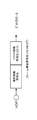
続いて、第1実施形態で説明したレイアウトの設定方法を用いて、MPEG2画像を含むMPEG4のテレビ放送の映像を表示する場合の説明を図26を用いて行う。第2実施形態では、図26に示す野球中継全体の画像で背景や選手を含む中継画像401がMPEG2画像であるとする。その他のオブジェクトである得点表示オブジェクト310、カウント表示オブジェクト311および展開に応じた上記以外のオブジェクトはMPEG4のデータからなる。すなわち、MPEG2画像を含むMPEG4のテレビ放送の映像表示例である。このときのMPEG4のビットストリーム例を図32に示す。
【0151】
図32に示すMPEG4のビットストリームには、MPEG2のデータストリームである野球中継画像401のデータがオブジェクト2として多重化されている。MPEG2のデータストリームは、一般的にオーディオ、ビデオおよびシステムデータ(MPEG2付加情報)の三種のデータから構成される。オブジェクト2には、伝送に関する所定のタイミング調整に従い、所定量毎のセグメントに分けられたMPEG2データストリームがそれぞれ多重化される。MPEG2とMPEG4とでは、下位レベルで共通化可能な符号化/復号回路もあるので、必要であれば共通化して、符号化/復号に関する無駄を避けた処理を行う。
【0152】
このように、MPEG2方式により符号化された画像および/またはサウンドデータを含むMPEG4方式のTV放送であっても、第1実施形態で説明したようなレイアウト設定が可能になる。
【0153】
表示画像のレイアウト設定データについては、第1実施形態と同様に、シーン記述情報から得られるオブジェクト配置情報を基に、ユーザによりレイアウトが変更されたオブジェクトの位置データを算出し、番組のカテゴリ情報、対象のオブジェクト情報および各部の制御データを対応させたレイアウト設定データとして記憶しておく。また、表示に関する動作も第1実施形態と同様である。
【0154】
第2実施形態は、MPEG2画像が多重化されたMPEG4のテレビ放送であるから、MPEG2コンテンツ、例えば現場中継などに用いる画像中継システムなどとの複合する場合に、MPEG2装置の出力を、複雑なデータ変換を介さずに、MPEG4の放送システムに流用でき、MPEG2とMPEG4との親和性から扱いも容易である。なお、中継画像などに限らず、代表的なMPEG2映像装置であるDVDを用いた資料映像表示などの多重画像出力例や、または他のMPEG2装置を用いた場合にも、勿論利用可能である。
【0155】
また、MPEG2とMPEG4とでは、共通化できる符号化/復号回路も多数あるので、システムの効率化に加え、回路構成も複雑な構成を必要とせずに効果的である。勿論、ソフトウェアデコーダの場合でもシステムの効率化は図れる。
【0156】
本実施形態によれば、第1実施形態の効果に加えて、MPEG2で符号化されたテレビ情報を、MPEG4テレビシステムにも流用できるようにしたので、従来あるコンテンツをそのまま使え、かつMPEG2をわざわざMPEG4にデータ変換する必要もないので、扱いが容易であり非常に効果的である。
【0157】
【第3実施形態】
以下、本発明にかかる第3実施形態のテレビ放送受信装置を説明する。なお、本実施形態において、第1実施形態と略同様の構成については、同一符号を付して、その詳細説明を省略する。
【0158】
本実施形態のレイアウト設定の対象オブジェクトは、放送データに含まれているオブジェクトに限らず、受信装置内で生成された画像であってもよい。このような受信装置内で生成される画像の例としては、文字情報などからなる時間情報およびタイトル、並びに、CGその他のグラフィックスなどが考えられる。本実施形態は、時間情報、タイトルおよびグラフィックスなどの表示位置を番組のカテゴリに対応させて自動的に変化させるものである。
【0159】
キャラクタ画像、例えば時間情報に関しては、MPEG4ビットストリームの追加データに含まれて送られてくる時間表示の基になる時間データや、テレビ放送受信装置内のクロック信号などを利用して、キャラクタ発生部40で生成される。さらに、キャラクタ発生部40は、追加データ中に受信装置内のクロックによる時間表示を行わせるコマンドが存在する場合、または、システムコントローラ38により独自に時間表示命令が発行された場合、これに従い、内部クロックを用いてそれぞれのコマンドに応じた時間表示画像を出力する。なお、実際に時間表示画像103を生成する、つまりキャラクタ発生動作の役割を担うのはキャラクタ発生部40およびキャラクタのデータが格納されたメモリ42であり、画像の合成は表示制御部34が行い、システムコントローラ38はそれらを制御することで時間表示画像103を生成させ表示させる。
【0160】
なお、MPEG2データストリームのサブコード内に一情報として含まれるタイムスタンプを利用しても同様の動作を実現できる。タイトルやグラフィックスに関する画像生成も同様であり、追加データに含まれたコマンドに従い、適切なタイミングで所定の画像が生成、合成、表示される。第1実施形態で取り上げた野球中継放送では、例えば、得点表示オブジェクト310の代わりにチーム名および得点を示す付加情報を追加データから取り出し、チーム名および得点を表す画像を生成する、なども考えられる。このように、受信装置内で生成された画像を、放送データに含まれるオブジェクトの如く扱うようにすれば、より扱いやすいシステムが構築できる。
【0161】
本実施形態の受信装置内で生成したキャラクタや画像のレイアウト設定に関しては、生成されたキャラクタや画像のレイアウト位置(オブジェクト位置)をデータ化し、その位置データ、番組のカテゴリ情報、そのキャラクタや画像(オブジェクト)の識別情報、および、キャラクタや画像の生成動作の制御を含む各部の制御データを、レイアウト設定データとして記憶しておく。なお、位置データの設定は図20および図21で説明した方法と同様である。これに加えて、メモリ42から読み出すキャラクタ生成用データや、キャラクタ発生部40で生成するキャラクタの生成動作をコマンドに対応させて制御し、適切なキャラクタを生成させる。
【0162】
発生されたキャラクタや画像は、第1実施形態と同様、受信されたオブジェクトと合成され表示される。この場合もまた、番組のカテゴリ情報によって合成や表示方法が制御される。
【0163】
本実施形態によれば、第1実施形態の効果に加えて、受信装置内で生成したキャラクタや画像に対しても、レイアウト設定機能を実現することができるので、通信(伝送)にかかる負荷を低減する効果を有する。
【0164】
このように、ディジタルテレビ放送において、パーソナルコンピュータ(PC)との融合も容易になり、現在、PCのデスクトップ上で行っているようなレイアウト設定などを、テレビ映像に対してもカスタマイズできるので、テレビ放送とPCとの相性もよくなり、また、ディジタル複合製品の分野において市場拡大の効果が期待できる。
【0165】
【他の実施形態】
なお、本発明は、複数の機器(例えばホストコンピュータ、インタフェイス機器、リーダ、プリンタなど)から構成されるシステムに適用しても、一つの機器からなる装置(例えば、複写機、ファクシミリ装置など)に適用してもよい。
【0166】
また、本発明の目的は、前述した実施形態の機能を実現するソフトウェアのプログラムコードを記録した記憶媒体を、システムあるいは装置に供給し、そのシステムあるいは装置のコンピュータ(またはCPUやMPU)が記憶媒体に格納されたプログラムコードを読出し実行することによっても、達成されることは言うまでもない。この場合、記憶媒体から読出されたプログラムコード自体が前述した実施形態の機能を実現することになり、そのプログラムコードを記憶した記憶媒体は本発明を構成することになる。また、コンピュータが読出したプログラムコードを実行することにより、前述した実施形態の機能が実現されるだけでなく、そのプログラムコードの指示に基づき、コンピュータ上で稼働しているOS(オペレーティングシステム)などが実際の処理の一部または全部を行い、その処理によって前述した実施形態の機能が実現される場合も含まれることは言うまでもない。
【0167】
さらに、記憶媒体から読出されたプログラムコードが、コンピュータに挿入された機能拡張カードやコンピュータに接続された機能拡張ユニットに備わるメモリに書込まれた後、そのプログラムコードの指示に基づき、その機能拡張カードや機能拡張ユニットに備わるCPUなどが実際の処理の一部または全部を行い、その処理によって前述した実施形態の機能が実現される場合も含まれることは言うまでもない。
【0168】
【発明の効果】
以上説明したように、本発明によれば、ディジタルテレビ放送における画像(映像)の再生形態に関する新たな機能を提供することができる。
【図面の簡単な説明】
【図1】衛星放送を用いたディジタル放送受信機の構成例を示すブロック図、
【図2】複数種類のオブジェクトを同時に入力し符号化処理する構成例を示すブロック図、
【図3】ユーザ操作(編集)を考慮に入れたシステムの構成例示す図、
【図4】ビデオオブジェクトに関するVOP処理回路のエンコーダ側のブロック図、
【図5】ビデオオブジェクトに関するVOP処理回路のデコーダ側のブロック図、
【図6】 VOPの符号化および復号の全体構成を示すブロック図、
【図7A】 VOPを構成する情報を示す図、
【図7B】 VOPを構成する情報を示す図、
【図8】テキスチャ符号化のAC/DC予測符号化を説明するための図、
【図9A】スケーラビリティを実現するためのシンタックスの階層構造を説明するための図、
【図9B】スケーラビリティを実現するためのシンタックスの階層構造を説明するための図、
【図10A】ワープを説明する図、
【図10B】ワープの種類を説明する図、
【図11】ワープを説明する図、
【図12】シーン記述情報の構成例を示す図、
【図13】 MPEG4オーディオの符号化方式の種類を示す図、
【図14】オーディオ符号化方式の構成を示す図、
【図15】 MPEG4のシステム構造を説明する図、
【図16】 MPEG4のレイヤ構造を説明する図、
【図17】双方向復号を説明する図、
【図18】重要情報の複数回伝送を説明する図、
【図19】本発明にかかる実施形態のテレビ放送受信装置の構成例を示すブロック図、
【図20】レイアウト設定する際の位置データの設定方法を説明する図、
【図21】レイアウト設定する際のイメージと指示の入力方法とを説明する図、
【図22】レイアウト設定データの構成を説明する図、
【図23】一般的なMPEG4ビットストリームの構成を示す図、
【図24】本実施形態による映像の表示形態例を示す図、
【図25】本実施形態による映像の表示形態例を示す図、
【図26】本実施形態による映像の表示形態例を示す図、
【図27】本実施形態による映像の表示形態例を示す図、
【図28】本実施形態のテレビ放送受信装置の動作手順例を説明するフローチャート、
【図29】本実施形態のテレビ放送受信装置の動作手順例を説明するフローチャート、
【図30】 MPEG4によるテレビ放送を送信するためのシステムに搭載される符号化部の構成例を示すブロック図、
【図31】テレビ放送受信装置に搭載される復号部の構成例を示すブロック図、
【図32】 MPEG2画像を含むMPEG4のビットストリーム例を示す図である。[0001]
BACKGROUND OF THE INVENTION
The present invention relates to a broadcast receiving apparatus and method thereof, and more particularly to a broadcast receiving apparatus and method capable of receiving a digital television broadcast and reproducing images and sound.
[0002]
[Prior art]
In recent years, digital television broadcasting using satellite broadcasting and cable broadcasting has been started. By realizing digital broadcasting, images and voice Many effects are expected, such as improving the quality of sound including sound, increasing the types and volume of programs using compression technology, providing new services such as interactive services, and evolving reception formats.
[0003]
FIG. 1 is a block diagram showing a configuration example of a
[0004]
First, television (TV) information transmitted by a broadcasting satellite is received by the
[0005]
Further, the
[0006]
[Problems to be solved by the invention]
When a television program in terrestrial broadcasting or digital television broadcasting is reproduced on a home television, it is common to display the video sent from the broadcasting station as it is. In other words, an act of effectively changing the display form (layout), for example, not displaying an object in the video as necessary, or changing the size of the object is not performed. Such a function to change the display format effectively is necessary from the viewpoint of adding new functions of effective display methods in the process of multi-channel and multi-programming with the development of digital television broadcasting. It is considered one of the things.
[0007]
The following are examples of situations where you want to set the layout. Baseball broadcasts have different display layouts depending on the broadcasting station, even if they are programs of the same category. For this reason, for example, in order to view a score display object or the like in a common layout regardless of the broadcasting station, it is desirable that the user can set a layout that suits his / her preference. However, layout setting is difficult at present.
[0008]
The present invention relates to an image in digital television broadcasting. (Video) playback format The purpose is to provide new functions.
[0009]
[Means for Solving the Problems]
The present invention has the following configuration as one means for achieving the above object.
[0010]
A broadcast receiving apparatus according to the present invention includes a receiving unit that receives a digital data sequence of a television broadcast, a decoding unit that decodes an image, sound, and system data from the received digital data sequence, and the decoded system data. And control means for controlling the playback mode of the decoded image and / or sound based on the category information indicating the broadcast content included in the system data. And an image object constituting the decoded image Playback format corresponding to Setting data Is read from the storage means and applied to the broadcast program being received.
[0012]
The broadcast receiving method according to the present invention receives a digital data sequence of a television broadcast, decodes an image, sound and system data from the received digital data sequence, and based on the decoded system data, decodes the decoded image and / or Alternatively, each step of controlling the sound reproduction form includes category information indicating broadcast contents included in the system data. And image objects constituting the decoded image Playback format corresponding to Setting data Is read from the storage means and applied to the broadcast program being received.
[0014]
DETAILED DESCRIPTION OF THE INVENTION
[Overview]
This embodiment uses the concept of an object, which is a feature of MPEG4 coding, to enable the display position to be changed in units of objects, and is specific to the user and unified according to the program content regardless of the broadcasting station. Realize layout image (video) display. An object is a background image, a speaker and its voice, and MPEG4 encoding encodes / decodes each object and combines each object to express one scene.
[0015]
In the broadcast system using MPEG4, the specific layout setting function of the present embodiment is capable of manipulating the displayed image in units of objects for the display of real-time image information, and is unified according to the category information of the program A function for setting an image (video) display of the arranged layout. The layout corresponding to this category includes a predetermined position and a position arbitrarily set by the user.
[0016]
Also, in the present embodiment, object layout and layout control are performed when a layout corresponding to a category of a program is performed with reference to object information indicating the contents of the object.
[0017]
As described above, according to the present embodiment, it is possible to eliminate the drawbacks that are displayed in different layouts depending on the broadcasting station even for programs in the same category, and a layout that is unified for each category regardless of the broadcasting station. Can display common objects. In addition to having a default layout, it is also possible to arbitrarily set a layout preferred by the user. Therefore, it is possible to improve the visual effect and user interface quality of the user who views the digital television broadcast, and to add a new function to the video display of the television broadcast.
[0018]
In the following, a configuration example of a receiving apparatus that receives a digital television broadcast using the MPEG4 encoding method will be described as a receiving apparatus according to an embodiment of the present invention. First, a technology related to MPEG4 will be described in detail for each field. To do.
[0019]
[Outline of MPEG4]
[General structure of the standard]
The MPEG4 standard consists of four major items. Three of these items are similar to MPEG2, and are a visual part, an audio part, and a system part.
[0020]
● Visual part
An object encoding method that handles natural images, composite images, moving images, still images, and the like is defined as a standard. Also included are an encoding method suitable for correcting and repairing transmission path errors, a synchronous reproduction function, and hierarchical encoding. In terms of expression, “video” means a natural image, and “visual” includes a composite image.
[0021]
● Audio part
An object encoding method for natural sounds, synthesized sounds, and sound effects is defined as a standard. The video part and the audio part are devised to increase the encoding efficiency by defining a plurality of encoding methods and appropriately selecting a compression method suitable for the characteristics of each object.
[0022]
● System part
It stipulates the multiplexing processing of encoded video objects and sound objects and vice versa. In addition, buffer memory, time axis control and readjustment functions are included in this part. The video objects and sound objects encoded in the above visual part and audio part are integrated into the multiplexed stream of the system part together with scene configuration information describing the position, appearance time and disappearance time of the object in the scene. . As a decoding process, each object is separated / decoded from the received bit stream, and a scene is reconstructed based on the scene configuration information.
[0023]
[Object encoding]
In MPEG2, encoding is performed in units of frames or fields, but in order to realize reuse and editing of content, MPEG4 handles video data and audio data as objects (objects). There are the following types of objects:
sound
Natural image (background video: 2D fixed video)
Natural image (main subject video: no background)
Composite image
Character image
[0024]
FIG. 2 shows an example of a system configuration in which these are simultaneously input and encoded. The
[0025]
In this way, on the encoding side, a combination of a plurality of visual objects and audio objects is defined to express one scene (screen). As for visual objects, a scene combining a natural image and a composite image such as computer graphics can be configured. Further, by adopting the above-described configuration, for example, a synchronized reproduction of the subject video and the sound can be performed using a text-to-speech synthesis function. Note that transmission / reception or recording / reproduction is performed in the bit stream state.
[0026]
The decoding process is a reverse process of the previous encoding process. The
[0027]
On the decoding side, partial changes such as the position of visual objects included in the scene and the order of audio objects can be made. The object position can be changed by dragging, and the language can be changed by the user changing the audio object.
[0028]
In order to synthesize a scene by freely combining a plurality of objects, the following four items are defined.
[0029]
● Object coding
A visual object, an audio object, and an AV (audio visual) object obtained by combining them are set as encoding targets.
[0030]
● Scene synthesis
In order to define scene composition information and a composition method for composing a visual object, an audio object, and an AV object into a desired scene, a language in which Virtual Reality Modeling Language (VRML) is modified is used.
[0031]
● Multiplexing and synchronization
The format of a stream (elementary stream) in which each object is multiple-synchronized is determined. Quality of service (QOS) can also be set when this stream is sent to the network or stored in the recording device. QOS parameters include transmission path conditions such as maximum transmission rate, error rate, and transmission method, and decoding capability.
[0032]
● User operation (interaction)
A method for synthesizing visual objects and audio objects on the user terminal side is defined. An MPEG4 user terminal separates data sent from a network or a recording device into elementary streams and decodes each object. A scene is reconstructed from a plurality of encoded data based on the scene configuration information sent simultaneously.
[0033]
Figure 3 shows an example of a system configuration that takes user operations (editing) into consideration. FIG. 4 is a block diagram on the encoder side of the VOP processing circuit for the video object, and FIG. 5 is a block diagram on the decoder side.
[0034]
[VOP (Video Object Plane)]
Video encoding in MPEG4 is performed by dividing a target video object into a shape (Shape) and a picture (Texture). The unit of this video data is called VOP. FIG. 6 is a block diagram showing the overall configuration of VOP encoding and decoding.
[0035]
For example, when an image is composed of two objects, a person and a background, each frame is divided into two VOPs and encoded. Information constituting each VOP is object shape information, motion information, and texture information, as shown in FIG. 7A. On the other hand, the decoder separates the bitstreams for each VOP and decodes them individually, and then combines them to form an image.
[0036]
Thus, by introducing the VOP structure, when the image to be processed is composed of a plurality of video objects, it can be divided into a plurality of VOPs and individually encoded / decoded. When the number of VOPs is 1 and the object shape is a rectangle, encoding is performed in units of frames as in the past, as shown in FIG. 7B.
[0037]
There are three types of VOPs: intra-frame coding (I-VOP), forward prediction (P-VOP), and bidirectional prediction (B-VOP). The prediction unit is a 16 × 16 pixel macroblock (MB).
[0038]
Bidirectional prediction B-VOP is a method for predicting a VOP from both the past VOP and the future VOP in the same way as MPEG1 and MPEG2 B pictures. Then, four types of modes of direct coding / forward coding / backward coding / bidirectional coding can be selected for each macroblock. This mode can be switched in MB or block units. Bi-directional prediction using P-VOP motion vector scaling.
[0039]
[Shape coding]
In order to handle an image in object (object) units, the shape of the object must be known at the time of encoding and decoding. Further, in order to express an object such as glass through which an object behind can be seen, information indicating the transparency of the object is required. The information on the shape of the object and the transparency of the object are collectively referred to as shape information. The encoding of shape information is called shape encoding.
[0040]
[Size conversion processing]
Binary shape coding is a method of coding a boundary pixel by determining whether the pixel is outside or inside the object. Therefore, the smaller the number of pixels to be encoded, the smaller the amount of generated code. However, if the macroblock size to be encoded is reduced, the original shape code is degraded and transmitted to the receiving side. Therefore, how much the original information is degraded by the size conversion is measured, and a macro block size as small as possible is selected as long as a size conversion error equal to or less than a predetermined threshold value is obtained. Specific size conversion ratios include three types: full size, vertical / horizontal 1/2 times, and vertical / horizontal 1/4 times.
[0041]
The shape information of each VOP is given as an 8-bit α value and is defined as follows.
α = 0: Outside the corresponding VOP
α = 1 to 254: Displayed in a translucent state with other VOPs
α = 255: Display area of the corresponding VOP only
[0042]
Binary shape coding is a case where the α value takes 0 or 255, and the shape is expressed only inside and outside the corresponding VOP. Multi-level shape coding is a case where α values can take all values from 0 to 255, and can represent a state in which a plurality of VOPs are semitransparently superimposed.
[0043]
Similar to texture coding, motion compensated prediction with one pixel accuracy is performed for each block of 16 × 16 pixels. When the entire object is encoded in-plane, the shape information is not predicted. As the motion vector, a difference between motion vectors predicted from adjacent blocks is used. The obtained difference value of the motion vector is encoded and then multiplexed into a bit stream. In MPEG4, the shape information of the block unit predicted by motion compensation is binary shape encoded.
[0044]
● Feathering
In addition, even in the case of a binary shape, feathering (border shape smoothing) is used to smoothly change the boundary from opaque to transparent. The feathering includes a linear feathering mode that linearly interpolates boundary values and a feathering filter mode that uses a filter. Multi-valued shapes with constant opacity have a constant alpha mode that can be combined with feathering.
[0045]
[Texture coding]
It encodes the luminance component and color difference component of an object, and processes in the order of DCT (Discrete Cosine Tranfer), quantization, predictive coding, and variable length coding in field / frame units.
[0046]
DCT uses a block of 8 × 8 pixels as a processing unit, but if the object boundary is within the block, the pixel outside the object is compensated by the average value of the object. After that, a 4-tap two-dimensional filter process is performed to prevent a phenomenon in which a large pseudo peak occurs in the DCT coefficient.
[0047]
Quantization uses either the ITU-T Recommendation H.263 quantizer or the MPEG2 quantizer. If MPEG2 quantizer is used, nonlinear quantization of DC component and frequency weighting of AC component are possible.
[0048]
The in-plane coding coefficient after quantization is predictively coded between blocks before variable length coding, and redundant components are deleted. In particular, MPEG4 predictively encodes both DC and AC components.
[0049]
As shown in Fig. 8, texture coding AC / DC predictive coding examines the difference (gradient) of the corresponding quantization coefficient between blocks adjacent to the target block, and uses the smaller quantization coefficient for prediction. . For example, when the DC coefficient x of the block of interest is predicted, if the DC coefficients of the corresponding adjacent blocks are a, b, and c, the following occurs.
| a-b | If <| b-c |, use DC coefficient c for prediction
If | a-b | ≥ | b-c |, use DC coefficient a for prediction
[0050]
When predicting the AC coefficient X of the block of interest, the coefficient used for prediction is selected in the same manner as described above, and then normalized with the quantization scale value QP of each block.
[0051]
Predictive coding of DC components is performed by examining the difference in DC components between adjacent blocks (vertical gradient) between adjacent blocks and the difference in DC components (horizontal gradient) between blocks adjacent to the left and right. The difference from the DC component of the block is encoded as a prediction error.
[0052]
The prediction encoding of the AC component uses the coefficient corresponding to the adjacent block in accordance with the prediction encoding of the DC component. However, since there is a possibility that the value of the quantization parameter is different between blocks, the difference is obtained after normalization (quantization step scaling). Presence / absence of prediction can be selected for each macroblock.
[0053]
Thereafter, the AC component is zigzag scanned and three-dimensional (Last, Run and Level) variable length encoded. Here, Last is a 1-bit value indicating the end of a non-zero coefficient, Run is a zero duration, and Level is a non-zero coefficient value.
[0054]
For variable length coding of the DC component subjected to in-plane coding, either a variable length coding table for DC component or a variable length table for AC component is used.
[0055]
[Motion compensation]
In MPEG4, a video object plane (VOP) having an arbitrary shape can be encoded. As described above, VOP includes in-plane coding (I-VOP), forward prediction coding (P-VOP), and bidirectional prediction coding (B-VOP) depending on the type of prediction. Use macroblocks of 16 lines x 16 pixels or 8 lines x 8 pixels. Therefore, there are macroblocks that straddle the VOP boundary. In order to improve the prediction efficiency of the VOP boundary, padding (complementation) and polygon matching (matching of only the object portion) are performed on the macroblock on the boundary.
[0056]
[Wavelet coding]
Wavelet transformation is a transformation method that uses a plurality of functions obtained by enlarging / reducing / translating one solitary wave function as a transformation base. This still image coding mode (Wavelet Transform) using wavelet transform is various, especially when dealing with a computer graphics (CG) image combined with a natural image. It is suitable as a high-quality encoding method with spatial resolution. In wavelet coding, an image can be coded all at once without being divided into blocks. Therefore, block distortion does not occur even at a low bit rate, and mosquito noise can be reduced. In this way, MPEG4 still image coding mode has a wide range of scalability from low-resolution and low-quality images to high-resolution and high-quality images, processing complexity, and coding efficiency trade-offs depending on the application. Can be adjusted.
[0057]
[Hierarchical coding (scalability)]
In order to realize scalability, a hierarchical structure of syntax as shown in FIGS. 9A and 9B is configured. Hierarchical coding is realized, for example, by coding “difference information” that improves the image quality of the base layer in the reinforcement layer, with the base layer as the lower layer and the reinforcement layer as the upper layer. In the case of spatial scalability, the base layer represents a low-resolution moving image, and the “base layer + reinforcement layer” represents a high-resolution moving image.
[0058]
In addition to improving the image quality of the entire image hierarchically, there is a function of improving the image quality of only the object region in the image. For example, in the case of temporal scalability, the base layer is obtained by coding the entire image at a low frame rate, and the reinforcement layer is obtained by coding data for improving the frame rate of a specific object in the image.
[0059]
● Time scalability
The temporal scalability shown in FIG. 9A can layer the frame speed and increase the frame speed of the object in the reinforcement layer. Whether to hierarchize can be set for each object. There are two types of reinforcement layers, and
[0060]
● Spatial scalability
Spatial scalability shown in FIG. 9B layers the spatial resolution. The base layer can be down-sampled of any size and is used for prediction of the reinforcement layer.
[0061]
[Sprite coding]
A sprite is a planar object that can express movement, rotation, deformation, and the like as a whole, such as a background image in a three-dimensional space image. This method of encoding a planar object is called sprite encoding.
[0062]
There are four types of sprite coding: static / dynamic and online / offline. More specifically, a static sprite that is configured to send object data to a decoder in advance and transmit only global motion coefficients in real time, and is obtained by direct conversion of a template object. A dynamic sprite obtained by predictive coding from the previous sprite in time. An off-line sprite that is encoded in advance by in-plane encoding (I-VOP) and transmitted to the decoder side. There are online sprites that are created simultaneously at the encoder and decoder during encoding.
[0063]
Techniques studied for sprite coding include static sprite coding, dynamic sprite coding, and global motion compensation.
[0064]
● Static sprite coding
Static sprite coding is a method of expressing an image by previously coding a background (sprite) of the entire video clip and geometrically converting a part of the background. Some of the cut out images can express various deformations such as translation, enlargement / reduction, and rotation. In this regard, as shown in FIG. 10A, expressing viewpoint movement in a three-dimensional space by moving, rotating, enlarging / reducing, or deforming an image is called warp.
[0065]
Warp types include perspective transformation, affine transformation, isotropic expansion (a) / rotation (θ) / movement (c, f), and translation, and are represented by the equations in FIG. 10B. Movement, rotation, enlargement / reduction, deformation, etc. are represented by the coefficients of the equation shown in FIG. 10B. Sprite generation is performed off-line before the start of encoding.
[0066]
In this way, static sprite coding is realized by cutting out a partial region of the background image and warping the region. A partial area included in the sprite (background) image shown in FIG. 11 is warped. For example, the background image is an image of a spectator seat in a tennis game, and the warped area is an image including a moving object such as a tennis player. In static sprite encoding, only the geometric transformation parameters are encoded, and the prediction error is not encoded.
[0067]
● Dynamic sprite coding
In static sprite encoding, sprites are generated before encoding. On the other hand, in dynamic sprite encoding, sprites can be updated online while encoding. Also, it differs from static sprite coding in that the prediction error is coded.
[0068]
● Global motion compensation (GMC)
Global motion compensation is a technique that compensates motion by representing motion of an entire object as a single motion vector without dividing the motion into blocks, and is suitable for motion compensation of a rigid body. It is the same as the static sprite coding in that the reference image becomes the immediately preceding decoded image instead of the sprite and the prediction error is encoded. However, the fact that a memory for storing sprites is not required and that shape information is not required is different from static sprite encoding and dynamic sprite encoding. This is effective for the movement of the entire screen and images including zoom.
[0069]
[Scene structure description information]
Objects are synthesized based on the scene configuration information. In MPEG4, configuration information for synthesizing each object into a scene is transmitted. When the individual encoded objects are received, the scene configuration information can be used to synthesize the scene as intended by the transmission side.
[0070]
The scene configuration information includes the display time and display position of the object, and these are described as tree-like node information. Each node has relative time information and relative space coordinate position information on the time axis with respect to the parent node. Languages for describing scene configuration information include BIFS (Binary Format for Scenes) with modified VRML and AAVS (Adaptive Audio-Visual Session Format) using Java (TM). BIFS is a format that describes MPEG4 scene configuration information in binary. AAVS is based on Java (TM) and has a high degree of freedom and is positioned to supplement BIFS. FIG. 12 is a diagram showing a configuration example of scene description information.
[0071]
[Scene description]
Scene description is done by BIFS. Here, we will focus on scene graphs and nodes, which are common concepts between VRML and BIFS.
[0072]
The node specifies attributes such as light source, shape, material, color, and coordinates, and grouping of lower nodes accompanied by coordinate transformation. Taking the object-oriented idea, the arrangement and appearance of each object in the three-dimensional space is determined by tracing a tree called a scene graph from the node at the vertex and inheriting the attribute of the upper node. If a media object, for example, a bit stream of MPEG4 video is allocated to a node corresponding to a leaf in synchronization, a moving image can be combined with other graphics and displayed in a three-dimensional space.
[0073]
Differences from VRML are as follows. The MPEG4 system supports the following with BIFS:
(1) MPEG4 video VOP coding two-dimensional overlap description and MPEG4 audio composition description
(2) Continuous media stream synchronization processing
(3) Dynamic behavior representation of objects (eg sprites)
(4) Standardized transmission format (binary)
(5) Dynamically change the scene description during the session
[0074]
Except for VRML nodes such as Extrusion, Script, Proto, and ExtemProto, almost all VRML nodes are supported by BIFS. The new MPEG4 special nodes added in BIFS are as follows.
(1) Node for 2D / 3D composition
(2) Node for 2D graphics and text
(3) Animation node
(4) Audio node
[0075]
It should be noted that VRML did not support 2D compositing except for special nodes such as the background, but BIFS has extended the description to handle text, graphic overlay, and MPEG4 video VOP encoding on a pixel-by-pixel basis. Yes.
[0076]
In the animation node, a special node for MPEG4 CG image such as a face composed of 3D mesh is defined. There is a message (BIFS Update) that can dynamically replace, delete, add and change attributes in the scene graph, and it is possible to display a new moving image on the screen or add a button during the session become. BIFS can be realized by replacing VRML reserved words, node identifiers, and attribute values with binary data almost on a one-to-one basis.
[0077]
[MPEG4 audio]
FIG. 13 shows the types of MPEG4 audio encoding methods. Audio and sound coding includes parametric coding, CELP (Code Excited Linear Prediction) coding, and time / frequency transform coding. Furthermore, it also incorporates SNHC (Synthetic Natural Hybrid Coding) audio functions and includes SA (Structured Audio) coding and TTS (Text to Speech) coding. SA is a structural description language for synthesized musical sounds including MIDI (Music Instrument Degital Interface), and TTS is a protocol for sending intonation and phonological information to an external text-to-speech synthesizer.
[0078]
FIG. 14 shows the configuration of the audio encoding method. In FIG. 14, the input sound signal is preprocessed (201), and the three encodings of parametric encoding (204), CELP encoding (205) and time / frequency encoding (206) are used according to the band. Then, the signal is divided (202) and input to an encoder suitable for each. Also, the signal analysis control (203) analyzes the input audio signal and generates control information for assigning the input audio signal to each encoder.
[0079]
Subsequently, the parametric coding core (204), the CELP coding core (205), and the time / frequency transform coding core (206), which are different encoders, perform coding processing based on each coding method. Execute. These three types of encoding will be described later. Audio data subjected to parametric coding and CELP coding is subjected to small step enhancement (207), and audio data subjected to time / frequency transform coding and small step enhancement is subjected to large step enhancement (208). The small step enhancement (207) and the large step enhancement (208) are tools for reducing distortion generated in each encoding process. Thus, the audio data enhanced by a large step becomes an encoded sound bitstream.
[0080]
The above is the description of the configuration of the sound encoding system in FIG. 75. Next, each encoding system will be described with reference to FIG.
[0081]
● Parametric coding
A sound signal including an audio signal and a musical sound signal is expressed by parameters such as frequency, amplitude, and pitch, and encoded. It includes harmonic vector drive coding (HVXC) for audio signals and individual spectrum (IL) coding for musical signals.
[0082]
HVXC coding is mainly intended for 2k to 4kbps speech coding. Voice signals are classified into voiced and unvoiced sounds, and the voiced sound is a harmonic of the residual signal of the linear prediction coefficient (LPC). ) Vector quantize the structure. For unvoiced sounds, the prediction residual is subjected to vector excitation coding as it is.
[0083]
IL coding is aimed at coding a musical sound of 6 k to 16 kbps, and a signal is modeled with a line spectrum and coded.
[0084]
CELP encoding
In this method, an input sound signal is separated into spectral envelope information and sound source information (prediction error) and encoded. The spectral envelope information is represented by a linear prediction coefficient calculated from the input sound signal by linear prediction analysis. MPEG4 CELP encoding includes narrowband CELP with a bandwidth of 4 kHz and wideband CELP with a bandwidth of 8 kHz. A bit rate can be selected between k and 24 kbps.
[0085]
● Time / frequency transform coding
This is an encoding method aiming at high sound quality. This includes an AAC (Advanced Audio Coding) compliant scheme and TwinVQ (Transform-domain Weighted Interleave Vector Quantization). This time / frequency transform coding incorporates an auditory psychological model, and has a mechanism for adaptive quantization using the auditory masking effect.
[0086]
The AAC compliant system is a mechanism for frequency-converting audio signals using DCT and performing adaptive quantization while using the auditory masking effect. The adaptive bit rate is 24k to 64kbps.
[0087]
The TwinVQ method flattens the MDCT coefficient of an audio signal using a spectral envelope obtained by linear prediction analysis of the audio signal. After interleaving, vector quantization is performed using two code lengths. The adaptive bit rate is 6k-40kbps.
[0088]
[System structure]
The MPEG4 system part defines multiplexing, demultiplexing and composition. Hereinafter, the system structure will be described with reference to FIG.
[0089]
In multiplexing, each object stream that is output from the video encoder and audio encoder, and elementary streams such as scene configuration information that describes the spatio-temporal arrangement of each object are packetized at the access unit layer. The In the access unit layer, a time stamp and a reference clock for synchronization in units of access units are added as headers. The packetized stream is then multiplexed in the FlexMux layer in units of display and error resilience and sent to the TransMux layer.
[0090]
In the TransMux layer, an error correction code is added in the protection sublayer according to the necessity of error resilience. Finally, it is sent out to the transmission path as a single TransMux stream in the multiple sublayer (Mux Sub Layer). The TransMux layer is not defined in MPEG4, but the Internet protocol UDP / IP (User Datagram Protocol / Internet Protocol), MPEG2 transport stream (TS), ATM (Asynchronous Transfer Mode) AAL2 (ATM Adaptation layer2), Existing network protocols such as a videophone multiplexing system using telephone lines (ITU-T recommendation H.223) and digital audio broadcasting can be used.
[0091]
It is also possible to bypass the access unit layer and the FlexMux layer so that the overhead of the system layer is reduced and can be easily embedded in a conventional transport stream.
[0092]
On the decoding side, in order to synchronize each object, a buffer (DB: Decoding Buffer) is provided after the demultiplexing (separation) to absorb the arrival time of each object and the deviation in decoding time. A buffer (CB: Composition Buffer) is also provided before composition to adjust the display timing.
[0093]
[Basic structure of video stream]
FIG. 16 shows the layer structure. Each hierarchy is called a class, and each class has a header. The header is various code information such as start code, end code, ID, shape and size.
[0094]
● Video stream
A video stream is composed of a plurality of sessions. A session is a series of complete sequences.
VS: Session consists of multiple objects
VO: Video object
VOL: Object is a sequence of objects including multiple layers
GOV: Object consists of multiple layers
VOP: Object layer consists of multiple planes
However, the plane is an object for each frame.
[0095]
[Error-resistant bitstream structure]
In MPEG4, the encoding method itself has resistance against transmission errors in order to cope with mobile communication (wireless communication) and the like. Error correction in the existing standard system is mainly performed on the system side, but the error rate is very high in networks such as PHS (Personal Handy phone System), and errors that cannot be corrected on the system side are in the video coding part. It is expected to leak. Considering this, MPEG4 assumes various error patterns that could not be corrected on the system side, and is an error-resistant coding method that suppresses error propagation as much as possible even under such an environment. Has been. Here, a specific technique of error resilience relating to image coding and a bit stream structure for that purpose will be described.
[0096]
● Reversible VLC (RVLC) and bidirectional decoding
As shown in FIG. 17, when it is confirmed that an error has occurred during decoding, the decoding process is temporarily stopped and the next synchronization signal is detected. At the stage where the next synchronization signal has been detected, the bit stream decoding process is performed in the reverse direction. The starting point of decoding increases without new additional information, and the amount of information that can be decoded when an error occurs can be increased as compared with the conventional case. “Bidirectional decoding” is realized by such a variable-length code that can be decoded from the forward direction as well as from the reverse direction.
[0097]
● Transmit important information multiple times
As shown in FIG. 18, a configuration capable of transmitting important information multiple times is introduced to enhance error tolerance. For example, in order to display each VOP at the correct timing, a time stamp is required, and this information is included in the first video packet. Even if this video packet is lost due to an error, decoding can be resumed from the next video packet by the bidirectional decoding structure. However, since this video packet has no time stamp, the display timing is not known after all. Become. For this reason, a structure has been introduced in which each video packet is flagged as HEC (Header Extension Code), and after this, important information such as a time stamp can be added. After the HEC flag, a time stamp and a VOP encoding mode type can be added.
[0098]
In the event of a loss of synchronization, decoding begins at the next synchronization recovery marker (RM), but each video packet contains the information required for it, the number of the first MB contained in the packet, and the quantum for that MB. The step size is placed immediately after RM. After that, the HEC flag is inserted. When HEC = '1', TR and VCT are added immediately after that. With these HEC information, even if the first video packet cannot be decoded and is discarded, decoding and display after the video packet set with HEC = '1' will be performed correctly. Whether or not HEC is set to “1” can be freely set on the encoding side.
[0099]
● Data partitioning
Since the encoding side repeats the encoding process in units of MB to form a bit stream, if an error is mixed in the middle, the subsequent MB data cannot be decoded. On the other hand, if multiple MB information is grouped into several groups, each is placed in the bitstream, and marker information is included at the boundary of each group, the bitstream will contain errors and the subsequent data Even if the data cannot be decoded, it is possible to re-synchronize with the marker at the end of the group and correctly decode the data of the next group.
[0100]
Based on the above idea, a data partitioning method (Data Partitioning) for grouping motion vectors and texture information (DCT coefficients, etc.) in units of video packets is employed. In addition, motion markers (MM:
Motion Marker) is placed.
[0101]
Even if an error is mixed in the motion vector information, the DCT coefficient that comes after the MM can be correctly decoded, so that MB data corresponding to the motion vector before the error mixing can be accurately reproduced together with the DCT coefficient. Even if an error is mixed in the texture portion, if the motion vector is correctly decoded, an image that is accurate to some extent can be interpolated and reproduced (concealed) using the motion vector information and the decoded previous frame information.
[0102]
● Variable-length interval synchronization method
Here, a synchronization recovery technique composed of variable-length packets will be described. An MB group including a synchronization signal at the head is called a “video packet”, and the number of MBs included in the MB group can be freely set on the encoding side. When an error is mixed in a bit stream using a variable length code (VLC), the subsequent codes cannot be synchronized and cannot be decoded. Even in such a case, subsequent information can be correctly decoded by detecting the next synchronization recovery marker.
[0103]
[Byte alignment]
In order to maintain consistency with the system, information is multiplexed in units of integer multiples of bytes. The bit stream has a byte alignment structure. To perform byte alignment, a stuff bit is inserted at the end of each video packet. Further, the stuff bit is also used as an error check code in the video packet.
[0104]
The stuff bit is composed of a code such as “01111” such that the first bit is “0” and all other bits are “1”. In other words, if the last MB in the video packet is correctly decoded, the next code is always' 0 ', and after that there should be a sequence of'1's that is one bit shorter than the stuff bit length. is there. If a pattern that violates this rule is detected, it means that the previous decoding has not been performed correctly, and it can be detected that an error has been mixed in the bitstream.
[0105]
As described above, "Overview of the international standard MPEG4 is determined" (Nikkei Electronics, September 22, 1997, p.147-168), "The whole picture of MPEG4 that has been visible" (Text of the Institute of Image Information and Television Engineers, 1997.10.2), The latest standardization trend and image compression technology (Nippon Industrial Technology Center seminar data 1997.2.3) etc. was referred and the MPEG4 technology was explained.
[0106]
[First Embodiment]
[Constitution]
Hereinafter, a television broadcast receiver according to an embodiment of the present invention will be described in detail with reference to the drawings. FIG. 19 is a block diagram showing a configuration example of the television broadcast receiving apparatus according to the embodiment of the present invention.
[0107]
The digital television broadcast signal is selected and received by the
[0108]
Subsequently, the television information is separated into each data multiplexed by the multiplexed
[0109]
On the other hand, the image data is decoded by an
[0110]
The display control performed by the
[0111]
The formed display image is converted into an analog form by the D /
[0112]
On the other hand, system data (including scene description data and additional data) is decoded by the system
[0113]
Object information is assigned to each object as a title by a command set commonly used by each television station. At the time of reception, by analyzing the object information, the contents of the object can be determined and classified. In the present embodiment, a layout setting function is realized that uses this object information to place an object having designated object information at a set position.
[0114]
Using the scene description data configured by the scene description
[0115]
When generating a display image that is not handled as an object, such as a time display screen or a title index, the
[0116]
Further, the user can input various commands via the
[0117]
[Layout settings]
Layout setting for discriminating category information and placing objects in a predetermined manner for each category can be executed by two methods. The first method is a method of setting a layout using pre-programmed default settings using layout setting data stored in the
[0118]
Here, a specific layout setting method will be described. FIG. 20 is a diagram for explaining a method for setting position data at the time of layout setting, and FIG. 21 is a diagram for explaining an image and an instruction input method for layout setting.
[0119]
There are two methods for positioning the object. The first method is a method of correcting (shifting) the position of the basic layout defined by the scene description data, and the second method is a method in which the user newly sets the position of the object at an arbitrary location. Both can be selected by a
[0120]
First, the shift method which is the first method will be described. Image data is input as an object, and the basic position of the object is represented by position data (X0, Y0) specified by scene description data. When the user wants to shift the object, the correction amount (ΔX, ΔY) is added to the position data (X0, Y0) by the
[0121]
This completes the description of the method for setting the layout of the designated image object. Object information for determining the target object is also necessary data as part of the layout setting data. The display process is controlled by the
[0122]
Next, FIG. 12 will be described. FIG. 12 illustrates the position setting method described so far. In the
[0123]
FIG. 21 shows a
[0124]
Category information is included in the television broadcast data. By using this category information, the set layout can be converted into data in association with the category information for each program and stored as layout setting data. As the storage location, a
[0125]
Next, layout setting data will be described. The layout setting data includes default setting data programmed and held in advance and data set by the user. Basically, the user setting data is based on the object arrangement information obtained from the scene description data, and in addition to the object arrangement information, the position of the object when the user sets the layout is converted into data, and the control data of each part and What is necessary is just to memorize | store as layout setting data with the object information used as object. The scene description data has already been described with reference to FIG. 12, but the information for designating the time at which each object should be displayed and the position at which each object should be displayed is arranged in a tree shape. It is.
[0126]
As other layout setting data configurations, as shown in FIG. 22, on / off data indicating whether or not to display the object, display position data when the display position is expressed two-dimensionally on the X and Y axes In addition, by holding data indicating the size, it can be used as layout setting data of a target object.
[0127]
FIG. 23 is a diagram showing a configuration of a general MPEG4 bit stream. In the database of
[0128]
FIGS. 24 and 25 are diagrams showing examples of screen settings in a baseball relay broadcast, and FIGS. 26 and 27 are diagrams showing display examples of a baseball relay broadcast.
[0129]
In baseball broadcast broadcasting, there are a
[0130]
After shifting to the layout setting mode, the user may place an object at an arbitrary position on the television screen, that is, a preferred position or an easy-to-see position by the above-described method while viewing the screen.
[0131]
In this way, by using the layout setting function of the present embodiment, the timing of displaying the object at the default setting or the user-set position as in one scene of the baseball relay broadcast shown in FIGS. A
[0132]
After the layout setting data once set is held, the layout setting function is activated by detecting the same category information, and it is determined whether or not the object is the target object from the object information. In the case of the target object, the layout is automatically displayed at the position based on the stored layout setting data at the display timing (scene). In addition, when the data structure of object information differs for every broadcasting station, you may make it reset object information.
[0133]
[Operation procedure]
28 and 29 are flowcharts for explaining an example of the operation procedure of the television broadcast receiving apparatus according to the present embodiment. FIG. 28 is a flow when the user sets a layout, and FIG.
[0134]
In the layout setting mode shown in FIG. 28, an object for setting a layout is selected from the objects constituting the image data in the television information (step S1). Then, the user places the selected (designated) object at an arbitrary position (step S2). When the arrangement of the selected object is completed, it is determined whether or not to end the layout setting (step S3), and when setting the layout for other objects, the process returns to step S1 to repeat the object selection and arrangement. When the layout setting is completed, the position of each object for which the layout is set is converted into data. Then, the category information, object information, position data, and control data of each part of the object are integrated and stored in the
[0135]
In the display mode shown in FIG. 29, television information is received (step S11), and program category information is detected from the system data added to the television information (step S12). The category information is information that adds information corresponding to the category (genre) of the program to the system data using a command set unified by each broadcasting station, and is used to divide the contents of the program roughly. It is. If the program category information is different for each broadcasting station, resetting means for ensuring consistency between broadcasting stations may be provided.
[0136]
Subsequently, it is determined whether layout setting data corresponding to the detected category information has already been saved (step S13). In the case of a category in which layout setting data is not stored, a television broadcast video is displayed with the basic layout sent from the broadcasting station (step S14).
[0137]
In the case of the category in which the layout setting data is stored, the layout setting data corresponding to the category information detected from the
[0138]
The display state of step S14 or step S16 is maintained until the program ends or the reception of a new program is started after moving to another channel. When reception of a new program is started, the current layout setting is reset, and the flow is repeated from the initial state of television broadcast reception in step S11.
[0139]
In the present embodiment, “baseball broadcast” is taken up as a program category. However, the present invention is not limited to this, and the same can be applied to “soccer broadcast” and categories of programs other than sports.
[0140]
As described above, according to the present embodiment, a user who views a digital television broadcast can arbitrarily set an object layout in accordance with program category information. Therefore, video display according to the program category and the user's preference is possible, and the quality improvement of the visual and auditory user interface can be expected, and the TV program display with more flexibility for the user. Is possible.
[0141]
When layout setting is performed for each category information of a program with reference to object information indicating the contents of the object, layout setting for only the specified object can be performed by performing object classification and arrangement control.
[0142]
Moreover, even in the same program category, it is possible to eliminate the drawbacks that are displayed in different layouts depending on the broadcasting station, and it is possible to display a common object with a unified layout for each program category regardless of the broadcasting station. it can.
[0143]
Second Embodiment
Hereinafter, a television broadcast receiver according to a second embodiment of the present invention will be described. Note that in the present embodiment, the same reference numerals are given to substantially the same configurations as those in the first embodiment, and detailed description thereof will be omitted.
[0144]
In the second embodiment, an object layout setting in a television broadcast that uses and substitutes an image encoded by an encoding method other than MPEG4 as one MPEG4 object will be described.
[0145]
Here, an example in which MPEG2 is used as a natural image encoding method will be described. That is, an explanation will be given regarding a television broadcast receiving apparatus that transmits an image encoded with MPEG2 (hereinafter, may be referred to as “MPEG2 image”) multiplexed in an MPEG4 bitstream, received, and displayed. The layout setting method in the second embodiment is the same as that described in the first embodiment, and the basic configuration and operation of the television broadcast receiving apparatus are the same as those described with reference to FIG. However, since the details of the
[0146]
FIG. 30 shows an encoding unit installed in a system for transmitting a television broadcast based on MPEG4 in a broadcasting station on the transmission side. The data multiplexer 5006 multiplexes the output from the
[0147]
FIG. 31 is a configuration example of a decoding unit mounted on the side that decodes an MPEG4 bit stream, that is, a television broadcast receiving apparatus. 31 includes a
[0148]
The received MPEG4 bit stream is separated into respective data by a
[0149]
Information for displaying the video of the television program is composed of the sound, image and system description data that are decoded in this way, each object and MPEG2 data is synthesized into a form to be output to the television by the
[0150]
Next, description will be made with reference to FIG. 26 when an MPEG4 television broadcast image including an MPEG2 image is displayed using the layout setting method described in the first embodiment. In the second embodiment, it is assumed that the
[0151]
In the MPEG4 bit stream shown in FIG. 32,
[0152]
As described above, the layout setting as described in the first embodiment is possible even for an MPEG4 system TV broadcast including an image and / or sound data encoded by the MPEG2 system.
[0153]
For the display image layout setting data, as in the first embodiment, based on the object arrangement information obtained from the scene description information, the position data of the object whose layout has been changed by the user is calculated, the program category information, The target object information and the control data of each part are stored as layout setting data in association with each other. The operation related to the display is the same as in the first embodiment.
[0154]
The second embodiment is an MPEG4 television broadcast in which MPEG2 images are multiplexed. Therefore, when combining with MPEG2 content, for example, an image relay system used for on-site relaying, the output of the MPEG2 device is complicated data. It can be diverted to the MPEG4 broadcasting system without conversion, and it is easy to handle because of the affinity between MPEG2 and MPEG4. Of course, the present invention can be used not only for relay images but also for multiple image output examples such as a material video display using a DVD, which is a typical MPEG2 video device, or other MPEG2 devices.
[0155]
In addition, since there are many encoding / decoding circuits that can be shared between MPEG2 and MPEG4, in addition to improving the efficiency of the system, the circuit configuration is effective without requiring a complicated configuration. Of course, even in the case of a software decoder, the efficiency of the system can be improved.
[0156]
According to the present embodiment, in addition to the effects of the first embodiment, the television information encoded with MPEG2 can be used for the MPEG4 television system, so that conventional contents can be used as they are, and MPEG2 is bothered. Since there is no need to convert the data to MPEG4, it is easy to handle and very effective.
[0157]
[Third Embodiment]
Hereinafter, a television broadcast receiver according to a third embodiment of the present invention will be described. Note that in the present embodiment, the same reference numerals are given to substantially the same configurations as those in the first embodiment, and detailed description thereof will be omitted.
[0158]
The layout setting target object of the present embodiment is not limited to the object included in the broadcast data, and may be an image generated in the receiving apparatus. As an example of an image generated in such a receiving apparatus, time information and titles composed of character information and the like, and CG and other graphics can be considered. In the present embodiment, the display positions of time information, titles, graphics, and the like are automatically changed in correspondence with program categories.
[0159]
For character images, for example, time information, the character generation unit uses time data that is included in the additional data of the MPEG4 bitstream and is sent as a basis for time display, or a clock signal in the television broadcast receiver. Generated at 40. Further, the
[0160]
The same operation can be realized by using a time stamp included as one information in the subcode of the MPEG2 data stream. The image generation related to the title and graphics is the same, and a predetermined image is generated, combined, and displayed at an appropriate timing in accordance with a command included in the additional data. In the baseball broadcast broadcast taken up in the first embodiment, for example, instead of the
[0161]
Regarding the layout setting of the character and image generated in the receiving apparatus of this embodiment, the layout position (object position) of the generated character and image is converted into data, the position data, program category information, the character and image ( Object) identification information and control data of each part including control of character and image generation operations are stored as layout setting data. The setting of the position data is the same as the method described with reference to FIGS. In addition, the character generation data read from the
[0162]
The generated character and image are combined with the received object and displayed as in the first embodiment. Also in this case, the composition and display method are controlled by the program category information.
[0163]
According to the present embodiment, in addition to the effects of the first embodiment, the layout setting function can be realized for characters and images generated in the receiving apparatus, so the load on communication (transmission) is reduced. It has the effect of reducing.
[0164]
In this way, digital TV broadcasting can be easily integrated with a personal computer (PC), and layout settings, etc. currently performed on the PC desktop can be customized for TV images. The compatibility between broadcasting and PC will be improved, and the effect of market expansion can be expected in the field of digital composite products.
[0165]
[Other Embodiments]
Note that the present invention can be applied to a system including a plurality of devices (for example, a host computer, an interface device, a reader, and a printer), and a device (for example, a copying machine and a facsimile device) including a single device. You may apply to.
[0166]
Another object of the present invention is to supply a storage medium storing software program codes for realizing the functions of the above-described embodiments to a system or apparatus, and the computer (or CPU or MPU) of the system or apparatus stores the storage medium. Needless to say, this can also be achieved by reading and executing the program code stored in the. In this case, the program code itself read from the storage medium realizes the functions of the above-described embodiments, and the storage medium storing the program code constitutes the present invention. Further, by executing the program code read by the computer, not only the functions of the above-described embodiments are realized, but also an OS (operating system) running on the computer based on the instruction of the program code. It goes without saying that a case where the function of the above-described embodiment is realized by performing part or all of the actual processing and the processing is included.
[0167]
Further, after the program code read from the storage medium is written into a memory provided in a function expansion card inserted in the computer or a function expansion unit connected to the computer, the function expansion is performed based on the instruction of the program code. It goes without saying that the CPU or the like provided in the card or the function expansion unit performs part or all of the actual processing and the functions of the above-described embodiments are realized by the processing.
[0168]
【The invention's effect】
As described above, according to the present invention, an image (video) in digital television broadcasting is recorded. Reproduction type New functions can be provided.
[Brief description of the drawings]
FIG. 1 is a block diagram showing a configuration example of a digital broadcast receiver using satellite broadcasting;
FIG. 2 is a block diagram illustrating a configuration example in which a plurality of types of objects are simultaneously input and encoded;
FIG. 3 is a diagram showing a configuration example of a system taking user operation (editing) into consideration;
FIG. 4 is a block diagram on the encoder side of a VOP processing circuit related to a video object;
FIG. 5 is a block diagram on the decoder side of a VOP processing circuit related to a video object;
FIG. 6 is a block diagram showing the overall configuration of VOP encoding and decoding;
FIG. 7A is a diagram showing information constituting a VOP;
FIG. 7B is a diagram showing information constituting a VOP;
FIG. 8 is a diagram for explaining AC / DC predictive coding of texture coding;
FIG. 9A is a diagram for explaining a hierarchical structure of syntax for realizing scalability;
FIG. 9B is a diagram for explaining a hierarchical structure of syntax for realizing scalability;
FIG. 10A is a diagram for explaining a warp;
FIG. 10B is a diagram for explaining types of warp;
FIG. 11 is a diagram for explaining a warp;
FIG. 12 is a diagram showing a configuration example of scene description information;
FIG. 13 is a diagram showing the types of MPEG4 audio encoding methods;
FIG. 14 is a diagram showing the configuration of an audio encoding system;
FIG. 15 is a diagram for explaining the MPEG4 system structure;
FIG. 16 is a diagram for explaining the MPEG4 layer structure;
FIG. 17 is a diagram for explaining bidirectional decoding;
FIG. 18 is a diagram for explaining multiple transmissions of important information;
FIG. 19 is a block diagram showing a configuration example of a television broadcast receiver according to an embodiment of the present invention;
FIG. 20 is a diagram for explaining a method of setting position data when setting a layout;
FIG. 21 is a diagram for explaining an image and instruction input method for layout setting;
FIG. 22 is a diagram for explaining the configuration of layout setting data;
FIG. 23 is a diagram showing the structure of a general MPEG4 bit stream;
FIG. 24 is a diagram showing an example of a video display mode according to the present embodiment;
FIG. 25 is a diagram showing an example of a video display mode according to the present embodiment;
FIG. 26 is a diagram showing an example of a video display mode according to the present embodiment;
FIG. 27 is a diagram showing an example of a video display mode according to the present embodiment;
FIG. 28 is a flowchart for explaining an operation procedure example of the television broadcast receiving apparatus of the present embodiment;
FIG. 29 is a flowchart for explaining an operation procedure example of the television broadcast receiving apparatus of the embodiment;
FIG. 30 is a block diagram showing a configuration example of an encoding unit installed in a system for transmitting a television broadcast by MPEG4;
FIG. 31 is a block diagram illustrating a configuration example of a decoding unit mounted on a television broadcast receiving device;
FIG. 32 is a diagram illustrating an example of an MPEG4 bit stream including an MPEG2 image.
Claims (11)
前記受信されたディジタルデータ列から画像、サウンドおよびシステムデータを復号する復号手段と、
前記復号されたシステムデータに基づき、前記復号された画像および/またはサウンドの再生形態を制御する制御手段とを有し、
前記制御手段は、前記システムデータに含まれる放送内容を示すカテゴリ情報、および、前記復号された画像を構成する画像オブジェクトに対応する再生形態の設定データを記憶手段から読み出して受信中の放送番組に適用することを特徴とする放送受信装置。Receiving means for receiving a digital data string of a television broadcast;
Decoding means for decoding image, sound and system data from the received digital data sequence;
Control means for controlling a reproduction mode of the decoded image and / or sound based on the decoded system data;
The control means reads out category information indicating the broadcast contents included in the system data , and setting data of a reproduction form corresponding to the image object constituting the decoded image from the storage means, and converts them into a broadcast program being received. A broadcast receiver characterized by being applied.
前記設定手段により設定されたレイアウトは、前記カテゴリ情報および前記画像オブジェクトの内容を示すオブジェクト情報とともに、前記再生形態の設定データとして前記記憶手段に記憶されることを特徴とする請求項1または請求項2に記載された放送受信装置。Further comprising a setting means for manually setting the layout of the image object,
The layout set by the setting unit is stored in the storage unit as setting data of the reproduction form together with the category information and object information indicating the content of the image object. The broadcast receiving apparatus described in 2.
前記受信したディジタルデータ列から画像、サウンドおよびシステムデータを復号し、
前記復号したシステムデータに基づき、前記復号した画像および/またはサウンドの再生形態を制御する各ステップを有し、
前記再生形態の制御は、前記システムデータに含まれる放送内容を示すカテゴリ情報、および、前記復号した画像を構成する画像オブジェクトに対応する再生形態の設定データを記憶手段から読み出して受信中の放送番組に適用することを特徴とする放送受信方法。Receive digital data stream of TV broadcast,
Decoding image, sound and system data from the received digital data sequence;
Based on the decoded system data, each step of controlling the playback mode of the decoded image and / or sound,
The control of the playback mode is performed by reading out category information indicating the broadcast content included in the system data and playback mode setting data corresponding to the image object constituting the decoded image from the storage means and receiving the broadcast program The broadcast receiving method characterized by being applied to.
前記設定したレイアウトは、前記カテゴリ情報および前記画像オブジェクトの内容を示すオブジェクト情報とともに、前記再生形態を示す情報として前記記憶手段の設定データに記憶されることを特徴とする請求項6または請求項7に記載された放送受信方法。And a step of manually setting the layout of the image object,
8. The set layout is stored in setting data of the storage unit as information indicating the reproduction mode together with the category information and object information indicating the contents of the image object. Broadcast receiving method described in 1.
Priority Applications (4)
| Application Number | Priority Date | Filing Date | Title |
|---|---|---|---|
| JP36613198A JP3927713B2 (en) | 1998-12-08 | 1998-12-08 | Broadcast receiving apparatus and method thereof |
| EP99309804A EP1018840A3 (en) | 1998-12-08 | 1999-12-07 | Digital receiving apparatus and method |
| US11/466,631 US7788690B2 (en) | 1998-12-08 | 2006-08-23 | Receiving apparatus and method |
| US11/466,515 US8081870B2 (en) | 1998-12-08 | 2006-08-23 | Receiving apparatus and method |
Applications Claiming Priority (1)
| Application Number | Priority Date | Filing Date | Title |
|---|---|---|---|
| JP36613198A JP3927713B2 (en) | 1998-12-08 | 1998-12-08 | Broadcast receiving apparatus and method thereof |
Publications (3)
| Publication Number | Publication Date |
|---|---|
| JP2000175155A JP2000175155A (en) | 2000-06-23 |
| JP2000175155A5 JP2000175155A5 (en) | 2006-01-26 |
| JP3927713B2 true JP3927713B2 (en) | 2007-06-13 |
Family
ID=18486001
Family Applications (1)
| Application Number | Title | Priority Date | Filing Date |
|---|---|---|---|
| JP36613198A Expired - Fee Related JP3927713B2 (en) | 1998-12-08 | 1998-12-08 | Broadcast receiving apparatus and method thereof |
Country Status (1)
| Country | Link |
|---|---|
| JP (1) | JP3927713B2 (en) |
Families Citing this family (9)
| Publication number | Priority date | Publication date | Assignee | Title |
|---|---|---|---|---|
| JP2002335499A (en) * | 2001-05-08 | 2002-11-22 | Sony Corp | Broadcast receiver |
| US7505485B2 (en) * | 2002-01-22 | 2009-03-17 | Microsoft Corporation | Methods and systems for start code emulation prevention and data stuffing |
| KR100571824B1 (en) * | 2003-11-26 | 2006-04-17 | 삼성전자주식회사 | Method for encoding/decoding of embedding the ancillary data in MPEG-4 BSAC audio bitstream and apparatus using thereof |
| JP2007215097A (en) * | 2006-02-13 | 2007-08-23 | Matsushita Electric Ind Co Ltd | Display data generating apparatus |
| WO2013077060A1 (en) * | 2011-11-22 | 2013-05-30 | 日本放送協会 | Receiver, program, and reception method |
| KR102396036B1 (en) | 2015-05-18 | 2022-05-10 | 엘지전자 주식회사 | Display device and controlling method thereof |
| CN112601121B (en) * | 2016-08-16 | 2022-06-10 | 上海交通大学 | Method and system for personalized presentation of multimedia content components |
| US10271069B2 (en) | 2016-08-31 | 2019-04-23 | Microsoft Technology Licensing, Llc | Selective use of start code emulation prevention |
| JP7263197B2 (en) * | 2019-09-30 | 2023-04-24 | 健樹 坂田 | Information processing system, information processing method and information processing program |
-
1998
- 1998-12-08 JP JP36613198A patent/JP3927713B2/en not_active Expired - Fee Related
Also Published As
| Publication number | Publication date |
|---|---|
| JP2000175155A (en) | 2000-06-23 |
Similar Documents
| Publication | Publication Date | Title |
|---|---|---|
| US8081870B2 (en) | Receiving apparatus and method | |
| US6377309B1 (en) | Image processing apparatus and method for reproducing at least an image from a digital data sequence | |
| US7054539B2 (en) | Image processing method and apparatus | |
| Koenen | MPEG-4 multimedia for our time | |
| US6567427B1 (en) | Image signal multiplexing apparatus and methods, image signal demultiplexing apparatus and methods, and transmission media | |
| Pereira | MPEG-4: Why, what, how and when? | |
| JP5409762B2 (en) | Image decoding apparatus and image decoding method | |
| JP3927713B2 (en) | Broadcast receiving apparatus and method thereof | |
| JP4306850B2 (en) | Broadcast receiving apparatus and method thereof | |
| US20030046691A1 (en) | Data processing apparatus and method | |
| JP4343411B2 (en) | Image processing method and apparatus, reproduction method, program, and storage medium | |
| JP4401463B2 (en) | Broadcast receiving apparatus and method thereof | |
| JP2004537931A (en) | Method and apparatus for encoding a scene | |
| JP4289753B2 (en) | REPRODUCTION METHOD AND DEVICE AND DISPLAY DEVICE | |
| JP7001639B2 (en) | system | |
| JP2001016582A (en) | Image processor and image processing method | |
| Puri et al. | Overview of the MPEG Standards | |
| Law et al. | The MPEG-4 Standard for Internet-based multimedia applications | |
| Danielsen | MPEG-4 for DTV | |
| JP2002044657A (en) | Image decoding method, image decoder and image decoding program recording medium | |
| Schaefer et al. | MPEG-4 for broadband communications | |
| Pereira | Av. Rovisco Pais, 1049-001 Lisboa Codex, Portugal E-mail: Fernando. Pereira@ lx. it. pt | |
| Puri | AT&T Labs-Research, Red Bank, New Jersey Alexandros Eleftheriadis Columbia University, New York, New York | |
| Puri et al. | AT&T Labs, Red Bank, New Jersey | |
| JP2005159878A (en) | Data processor and data processing method, program and storage medium |
Legal Events
| Date | Code | Title | Description |
|---|---|---|---|
| A521 | Written amendment |
Free format text: JAPANESE INTERMEDIATE CODE: A523 Effective date: 20051207 |
|
| A621 | Written request for application examination |
Free format text: JAPANESE INTERMEDIATE CODE: A621 Effective date: 20051207 |
|
| RD01 | Notification of change of attorney |
Free format text: JAPANESE INTERMEDIATE CODE: A7426 Effective date: 20051207 |
|
| RD03 | Notification of appointment of power of attorney |
Free format text: JAPANESE INTERMEDIATE CODE: A7423 Effective date: 20051207 |
|
| A977 | Report on retrieval |
Free format text: JAPANESE INTERMEDIATE CODE: A971007 Effective date: 20061020 |
|
| A131 | Notification of reasons for refusal |
Free format text: JAPANESE INTERMEDIATE CODE: A131 Effective date: 20061030 |
|
| A521 | Written amendment |
Free format text: JAPANESE INTERMEDIATE CODE: A523 Effective date: 20061222 |
|
| TRDD | Decision of grant or rejection written | ||
| A01 | Written decision to grant a patent or to grant a registration (utility model) |
Free format text: JAPANESE INTERMEDIATE CODE: A01 Effective date: 20070226 |
|
| A61 | First payment of annual fees (during grant procedure) |
Free format text: JAPANESE INTERMEDIATE CODE: A61 Effective date: 20070305 |
|
| R150 | Certificate of patent or registration of utility model |
Free format text: JAPANESE INTERMEDIATE CODE: R150 |
|
| FPAY | Renewal fee payment (event date is renewal date of database) |
Free format text: PAYMENT UNTIL: 20100309 Year of fee payment: 3 |
|
| FPAY | Renewal fee payment (event date is renewal date of database) |
Free format text: PAYMENT UNTIL: 20110309 Year of fee payment: 4 |
|
| FPAY | Renewal fee payment (event date is renewal date of database) |
Free format text: PAYMENT UNTIL: 20120309 Year of fee payment: 5 |
|
| FPAY | Renewal fee payment (event date is renewal date of database) |
Free format text: PAYMENT UNTIL: 20130309 Year of fee payment: 6 |
|
| FPAY | Renewal fee payment (event date is renewal date of database) |
Free format text: PAYMENT UNTIL: 20140309 Year of fee payment: 7 |
|
| LAPS | Cancellation because of no payment of annual fees |