JP2004184175A - Gas concentration sensor, and air-fuel mixture concentration detector for engine - Google Patents
Gas concentration sensor, and air-fuel mixture concentration detector for engine Download PDFInfo
- Publication number
- JP2004184175A JP2004184175A JP2002350129A JP2002350129A JP2004184175A JP 2004184175 A JP2004184175 A JP 2004184175A JP 2002350129 A JP2002350129 A JP 2002350129A JP 2002350129 A JP2002350129 A JP 2002350129A JP 2004184175 A JP2004184175 A JP 2004184175A
- Authority
- JP
- Japan
- Prior art keywords
- gas
- light
- detected
- mirror
- optical fibers
- Prior art date
- Legal status (The legal status is an assumption and is not a legal conclusion. Google has not performed a legal analysis and makes no representation as to the accuracy of the status listed.)
- Granted
Links
Images


Landscapes
- Investigating Or Analysing Materials By Optical Means (AREA)
- Ignition Installations For Internal Combustion Engines (AREA)
Abstract
Description
【0001】
【発明の属する技術分野】
本発明は、例えばエンジンの燃焼室内の混合気の濃度を検出するために用いられるガス濃度センサに関するものである。
【0002】
【従来の技術】
近年、インジェクタと呼ばれる燃料噴射装置が普及するにつれて、燃料を噴射するタイミングや噴射燃料量、つまり空燃比などの制御が容易になり、高出力化、低燃費化、排ガスのクリーン化などを促進することができるようになった。
しかしながら、燃焼室内の混合気の濃度、例えば濃度分布の状態をより正確に検出することができれば、更なる高出力化、低燃費化、排ガスのクリーン化などを達成することができる。このような要求に応えるべく、例えば赤外光等の所定の波長又は周波数の光を被検出ガスに入射し、当該被検出ガスを通過した光を取り出し、その光の強度から被検出ガスの濃度を検出することが提案されている(例えば非特許文献1参照)。
【0003】
更に、このガス濃度検出技術を用い、二本の光導波路、具体的には光ファイバを平行又は略平行に点火栓内に配設し、何れか一方の光ファイバから前記所定の波長又は周波数の光を被検出ガスに出射し、当該点火栓に設けた鏡でその光を反射し、当該被検出ガスを通過した反射光を他方の光ファイバに入射し、その反射光の強度からエンジン燃焼室内の混合気の濃度を検出するガス濃度センサが考えられている。
【0004】
【非特許文献1】
内燃機関シンポジウム、’00/9、冨田栄二他、「3.392μm赤外吸収方法用いたエンジンシリンダ内点火栓近傍炭化水素燃料濃度の計測」
【0005】
【発明が解決しようとする課題】
しかしながら、前記従来のガス濃度センサは、実際のエンジン運転状態では、低・中負荷の状態でしか使用できないという実情がある。特に、モータサイクル用エンジンや競技用エンジンは、使用回転域が高く、熱負荷が大きいため、例えば鏡が溶損してしまうとか、光ファイバを被覆している接着剤が溶損してしまうなどの問題がある。また、前記所定の波長又は周波数の光は、混合気の特定の成分に吸収されるが、同時に拡散してしまうので、反射光の回収量が少なく、感度が低い、所謂S/Nが悪いという問題もある。
【0006】
本発明は前記諸問題を解決すべく開発されたものであり、S/Nがよく、耐熱性に優れ、更に燃焼室内の混合気の濃度を正確に検出することができるガス濃度センサ及びエンジン用混合気濃度検出装置を提供することを目的とするものである。
【0007】
【課題を解決するための手段】
上記諸問題を解決するため、本発明のうち請求項1に係るガス濃度センサは、二以上の光導波路を平行又は略平行に配設し、所定の波長又は周波数の光を何れかの光導波路から被検出ガスに出射し、当該被検出ガス内を通り、鏡に反射したその反射光を異なる光導波路に入射し、その反射光の強度から被検出ガスの濃度を検出するためのガス濃度センサにおいて、前記反射光を入射するための光導波路を前記所定の波長又は周波数の光を被検出ガスに出射するための光導波路よりも多くしたことを特徴とするものである。
【0008】
また、本発明のうち請求項2に係るガス濃度センサは、二以上の光導波路を平行又は略平行に配設し、所定の波長又は周波数の光を何れかの光導波路から被検出ガスに出射し、当該被検出ガス内を通り、鏡に反射したその反射光を異なる光導波路に入射し、その反射光の強度から被検出ガスの濃度を検出するためのガス濃度センサにおいて、前記鏡をNi−Cr合金製としたことを特徴とするものである。
【0009】
また、本発明のうち請求項3に係るガス濃度センサは、前記請求項2の発明において、前記鏡を溶接により固着したことを特徴とするものである。
また、本発明のうち請求項4に係るガス濃度センサは、二以上の光導波路を平行又は略平行に配設し、所定の波長又は周波数の光を何れかの光導波路から被検出ガスに出射し、当該被検出ガス内を通り、鏡に反射したその反射光を異なる光導波路に入射し、その反射光の強度から被検出ガスの濃度を検出するためのガス濃度センサにおいて、前記二以上の光導波路をセラミックス系接着剤で被覆するように固着し、硬化後、セラミックス系接着剤ごと、光導波路の入出射端面を研削したことを特徴とするものである。
【0010】
また、本発明のうち請求項5に係るガス濃度センサは、前記請求項1乃至4の発明において、前記二以上の光導波路を点火栓内に配設したことを特徴とするものである。
また、本発明のうち請求項6に係るエンジン用混合気濃度検出装置は、一つの燃焼室に対し、前記鏡が当該燃焼室内に突出するようにして前記請求項1乃至5の何れかのガス濃度センサを二以上配設し、当該燃焼室内の異なる部位の混合気濃度を検出することを特徴とするものである。
【0011】
【発明の実施の形態】
以下、本発明の一実施形態について説明する。
図1は、例えばモータサイクル用のエンジン及びその制御装置の一例を示す概略構成である。このエンジン1は、比較的小排気量の単気筒4サイクルエンジンであり、シリンダボディ2、クランクシャフト3、ピストン4、燃焼室5、吸気管6、吸気バルブ7、排気管8、排気バルブ9、点火プラグ(点火栓)10、点火コイル11を備えている。また、吸気管6内には、アクセル開度に応じて開閉されるスロットルバルブ12が設けられ、このスロットルバルブ12の下流側の吸気管6に、燃料噴射装置としてのインジェクタ13が設けられている。このインジェクタ13は、燃料タンク19内に配設されているフィルタ18、燃料ポンプ17、圧力制御バルブ16に接続されている。なお、図中の符号30は例えば赤外光等の所定の波長又は周波数の光を創成するレーザ、符号31は前記レーザ30で創成された光を切り出すチョッパ(電子シャッタ)、符号32は後述する反射光の強度を検出する光強度検出器、符号33は光ファイバケーブルである。
【0012】
前記エンジン1の運転状態は、エンジンコントロールユニット15によって制御され、当該エンジンコントロールユニット15は、マイクロコンピュータ等の演算処理装置を備えて構成される。そして、このエンジンコントロールユニット15の制御入力、つまりエンジン1の運転状態を検出する手段として、クランクシャフト3の回転角度、つまり位相を検出するためのクランク角度センサ20、シリンダボディ2の温度又は冷却水温度、即ちエンジン本体の温度を検出する冷却水温度センサ21、排気管8内の空燃比を検出する排気空燃比センサ22、吸気管6内の吸気圧力を検出するための吸気圧力センサ24、吸気管6内の温度、即ち吸気温度を検出する吸気温度センサ25が設けられている。そして、前記エンジンコントロールユニット15は、これらのセンサの検出信号を入力し、前記燃料ポンプ17、圧力制御バルブ16、インジェクタ13、点火コイル11に制御信号を出力する。
【0013】
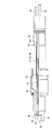
前記点火プラグ10には、燃焼室5内の混合気の濃度を検出するためのガス濃度センサが組み込まれている。具体的には、図2に示すように、例えば点火プラグ10の燃焼室5側を先端、逆側を後端としたとき、当該点火プラグ10の中心部には、後端部から中心電極41の先端部まで貫通孔51が形成されており、この貫通孔51に光ファイバロッド34が挿入されてガス濃度センサが構成されている。なお、前記貫通孔51の周囲には、円筒状の導電体52が配設されており、この導電体52を介して前記中心電極41に電力を供給する。また、後述するように点火プラグ10の先端部には鏡39が配設されるため、通常の点火プラグと異なり、前記中心電極41の側方に接地電極42が配設されている。ちなみに、図中の符号29はイグニッションケーブルである。
【0014】
前記貫通孔51の先端部には、光ファイバロッド34を熱負荷から保護するための透明なサファイヤロッド43が埋設されている。また、前記中心電極41の側方には、点火プラグ10の先端に向けて耐熱性のブラケット53が立設され、その先端部に、前記中心電極41、正確には前記サファイヤロッド43から所定の間隔を開けて鏡39が設けられている。この鏡39及びブラケット53は、従来、点火プラグの接地電極に使用されているNi−Cr合金製であり、当然ながら十分な耐熱性を有する。鏡39は、Ni−Cr合金製ブラケット53の先端部に形成され、研削により十分な鏡面を得てから、点火プラグ10本体に溶接により固着される。このように鏡39(ブラケット53)を溶接固着すると、例えばネジ止めなどに比して、熱伝達特性に優れる。また、Ni−Cr合金製の鏡39は、爆発の高温に曝されても、殆ど曇らないし、勿論、溶損することもない。
【0015】
一方、点火プラグ10の後端部には、金属製の連結部材54が取付けられており、この連結部材54にも前記貫通孔51が開口しており、その後端部には雌ネジが形成されている。前記光ファイバロッド34は、この連結部材54の後端部から挿入され、当該光ファイバロッド34に形成されている雄ネジを前記連結部材54の雌ネジに螺合して固定されている。この光ファイバロッド34と前記サファイヤロッド43との間には所定の空隙が形成されており、当該光ファイバロッド34を燃焼室5の高温から保護するように構成されている。
【0016】
前記光ファイバロッド34の中心部先端にはレンズ55が埋設されており、その後方に、複数本の光ファイバ35、36、即ち光導波路が平行又は略平行に配設されている。レンズ55は、光ファイバ35から出射される光の広がり角を調整して効率よくガス濃度検出部に導くためのものである。このレンズ55を装着する代わりにサファイヤロッド43の端面を架構してレンズ作用させてもよい。また、このほかにレンズのない構成にすることも可能である。レンズがないとやや効率が悪化するが、レーザ30を高出力のものにするとか、光強度検出器32を高感度のものにすることによって精度よくガス濃度を検出することが可能である。この構成では、点火栓内に組み込む部品点数が減少する分、小型化し易いという利点がある。
【0017】
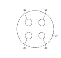
図3には、光ファイバロッド34中に配設されている光ファイバ35、36の配置の一例を示す。この例では、四本の光ファイバが配設され、そのうちの一本が前記所定の波長又は周波数の光を被検出ガスに入射するための入射光ファイバ35、残りの三本が、前記鏡に反射した反射光を前記光強度検出器に出射する出射光ファイバ36になる。前記入射光ファイバ35から出射した所定の波長又は周波数の光は、前記空隙、サファイヤロッド43を通り、被検出ガスを通過した後に鏡39に反射し、更に被検出ガス、サファイヤロッド43、空隙の順に通過して出射光ファイバ36に入射する。前述のように、所定の波長又は周波数の光、例えば赤外光は被検出ガスである混合気の炭化水素に吸収されるので、反射光の強度を検出すれば混合気の炭化水素量、即ち濃度が分かる。しかしながら、この濃度検出用の光は、混合気に吸収されると共に、混合気中に拡散もしてしまうので、反射光の回収量が少ないという問題がある。そこで、本実施形態では、四本の光ファイバのうちの一本を入射光ファイバ35、残りの三本を出射光ファイバ36とし、反射光の回収量を増大して、濃度検出感度を向上し、所謂S/Nを良好なものとする。
【0018】
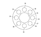
なお、入射光ファイバ35、出射光ファイバ36のレイアウトは、これ以外にも、例えば図4〜図6に示すものが挙げられる。このうち、図4のものは光ファイバロッドの中心部に一本の入射光ファイバ35を配設し、その外周に複数本の出射光ファイバ36を配設したものである。また、図5のものは、同じく光ファイバロッドの中心部に一本の入射光ファイバ35を配設し、その外周に複数本の出射光ファイバ36を配設したものであるが、入射光ファイバ35の径を大きくして被検出ガスへの検査光の入射量を増大したものである。また、図6のものは、光ファイバロッドの中心部に四本の入射光ファイバ35を配設し、その外周に複数本の出射光ファイバ36を配設したものであり、図5のものと同様に、被検出ガスへの検査光の入射量を増大することが可能となる。このように、出射光ファイバ36の数を入射光ファイバ35の数よりも大きくすることにより、感度を向上し、S/Nを良好なものとすることができる。
【0019】
前述した複数の光ファイバ35、36は、接着剤によって被覆され、一体に固着されている。本実施形態では、この接着剤にセラミックス系接着剤を用いた。セラミックス系接着剤の被覆層を符号37で示す。従来の接着剤は、所謂エポキシ系接着剤であり、熱に弱く、通常のエンジンの運転状態で容易に溶損してしまう。セラミックス系接着剤は耐熱性に優れるが、硬化後の研削が非常に困難である。特に、光ファイバの被覆に用いた場合には、接着剤の被覆層37と共に光ファイバの端面を研削する必要が生じる。本発明者等は、鋭意検討の末、硬化したセラミックス系接着剤ごと、光ファイバの端面を研削する技術を見出し、本実施形態のガス濃度センサを開発した。
【0020】
本実施形態のガス濃度センサ及びそれを用いたエンジン用混合気濃度検出装置によれば、S/N及び耐熱性に優れるため、低回転から高回転まで、高応答に混合気濃度を検出することが可能となる。図7aは、低スロットル開度から一気にスロットルを開いたときの混合気濃度の経時変化を示すものである。本実施形態では、非常に高応答に混合気濃度を検出することができるので、サンプリング周期を短くすることにより、例えば図7aのデータから図7bに示すような1サイクル間の混合気濃度変化を取り出すこともできるし、図7cに示すような回転数毎の混合気濃度変化、即ち過渡変化も取り出すことができる。
【0021】
また、本実施形態では、前述のような耐熱性の向上から、ガス濃度センサを組み込む点火プラグ10の大きさを小さくすることが可能となった、つまりガス濃度センサの小型化に成功した。従って、図8に示すように、前記鏡39部分が燃焼室5内に突出するようにして、一つの燃焼室5に対し、複数のガス濃度センサ(点火プラグ10)を取付け、夫々のガス濃度センサで燃焼室内の異なる部分の混合気濃度を検出することも可能である。このとき、例えば図9に示すように一つのレーザ30からの光をハーフミラー38で分光して各ガス濃度センサに供給したり、図10に示すように各ガス濃度センサの前記入射光ファイバ35を束ねて一つのレーザ30からの光を各入射光ファイバ35に入射するようにしたりすることにより、同位相の検査光を複数のガス濃度センサに供給することが可能となる。また、各入射光ファイバ35の入射端にレンズを介装して光のビーム径を調整すれば効率を向上することが可能となる。このようにして一つの燃焼室5の複数の箇所で混合気濃度を検出するようにすれば、燃焼室5内の混合気の濃度分布を検出することができる。
【0022】
なお、前記実施形態では、所定の波長又は周波数の光源としてレーザを用いたが、光源はこれに限定されない。例えば、混合気濃度を検出するためには赤外光が必要であるが、赤外光は熱体から放射するので、ヒータなどを用いることも可能である。
また、本発明のガス濃度センサは、エンジンの燃焼室内に限らず、あらゆる分野でガスの濃度を検出することが可能であり、特に熱負荷の大きい、高温条件で利用できる。その場合には、被検出ガスが効率よく吸収する光の波長又は周波数を設定すればよい。
【0023】
【発明の効果】
以上説明したように、本発明のうち請求項1に係るガス濃度センサによれば、所定の波長又は周波数の光を被検出ガスに出射するための光導波路よりも、その反射光を入射するための光導波路を多くしたことにより、反射光の回収量が多くなり、感度が向上し、S/Nが良好になる。
【0024】
また、本発明のうち請求項2に係るガス濃度センサによれば、鏡をNi−Cr合金製としたことにより、鏡の耐熱性が向上し、高回転型、高熱負荷エンジンにも適用可能となる。
また、本発明のうち請求項3に係るガス濃度センサによれば、鏡を溶接により固着したことにより、熱伝達特性が向上し、より高回転型、高熱負荷エンジンにも適用可能となる。
【0025】
また、本発明のうち請求項4に係るガス濃度センサによれば、二以上の光導波路をセラミックス系接着剤で被覆するように固着し、硬化後、セラミックス系接着剤ごと、光導波路の入出射端面を研削したことにより、光導波路被覆の耐熱性が向上し、高回転型、高熱負荷エンジンにも適用可能となる。
また、本発明のうち請求項5に係るガス濃度センサによれば、二以上の光導波路を点火栓内に配設したことにより、エンジンの燃焼室中、最も検出したい点火栓位置での混合気濃度の検出が可能となる。
【0026】
また、本発明のうち請求項6に係るエンジン用混合気濃度検出装置によれば、一つの燃焼室に対し、鏡が燃焼室内に突出するようにしてガス濃度センサを二以上配設し、当該燃焼室内の異なる部位の混合気濃度を検出する構成としたため、燃焼室内の混合気の分布状態まで検出することが可能となる。
【図面の簡単な説明】
【図1】モータサイクル用のエンジン及び混合気濃度検出装置の概略構成図である。
【図2】図1の点火プラグに配設されたガス濃度センサの詳細図である。
【図3】図2のガス濃度センサの光ファイバの配置図である。
【図4】図2のガス濃度センサの光ファイバの配置図である。
【図5】図2のガス濃度センサの光ファイバの配置図である。
【図6】図2のガス濃度センサの光ファイバの配置図である。
【図7】図1の混合気濃度検出装置による混合気濃度の検出結果の説明図である。
【図8】燃焼室の多点で混合気濃度を検出する説明図である。
【図9】検査光の分光方法の説明図である。
【図10】検査光の分光方法の説明図である。
【符号の説明】
1はエンジン
3はクランクシャフト
4はピストン
5は燃焼室
6は吸気管
7は吸気バルブ
8は排気管
9は排気バルブ
10は点火プラグ
11は点火コイル
12はスロットルバルブ
13はインジェクタ
15はエンジンコントロールユニット
16は圧力制御バルブ
17は燃料ポンプ
30はレーザ
31はチョッパ
32は光強度検出器
33は光ファイバケーブル
34は光ファイバロッド
35は入射光ファイバ
36は出射光ファイバ
37は接着剤被覆層
38はハーフミラー
39は鏡[0001]
TECHNICAL FIELD OF THE INVENTION
The present invention relates to a gas concentration sensor used for detecting the concentration of an air-fuel mixture in a combustion chamber of an engine, for example.
[0002]
[Prior art]
In recent years, with the spread of fuel injectors called injectors, it becomes easier to control the timing of fuel injection and the amount of injected fuel, that is, the air-fuel ratio, and to promote higher output, lower fuel consumption, and cleaner exhaust gas. Now you can do it.
However, if the concentration of the air-fuel mixture in the combustion chamber, for example, the state of the concentration distribution, can be detected more accurately, further higher output, lower fuel consumption, cleaner exhaust gas, and the like can be achieved. In order to respond to such a demand, for example, light of a predetermined wavelength or frequency such as infrared light is incident on the gas to be detected, light that has passed through the gas to be detected is extracted, and the concentration of the gas to be detected is determined from the intensity of the light. It has been proposed to detect (for example, see Non-Patent Document 1).
[0003]
Further, using this gas concentration detection technique, two optical waveguides, specifically, an optical fiber are disposed in a spark plug in parallel or substantially in parallel, and one of the optical fibers has the predetermined wavelength or frequency. The light is emitted to the gas to be detected, the light is reflected by a mirror provided on the ignition plug, the reflected light passing through the gas to be detected is incident on the other optical fiber, and the intensity of the reflected light is used to determine the intensity of the reflected light. A gas concentration sensor for detecting the concentration of an air-fuel mixture has been considered.
[0004]
[Non-patent document 1]
Internal combustion engine symposium, '00 / 9, Eiji Tomita et al., "Measurement of hydrocarbon fuel concentration near spark plug in engine cylinder using 3.392 µm infrared absorption method"
[0005]
[Problems to be solved by the invention]
However, there is a situation in which the conventional gas concentration sensor can be used only in a low / medium load state in an actual engine operation state. In particular, motorcycle engines and competition engines use a high rotation range and have a large heat load, so that, for example, the mirror is melted or the adhesive coating the optical fiber is melted. There is. In addition, the light of the predetermined wavelength or frequency is absorbed by a specific component of the air-fuel mixture, but is diffused at the same time. Therefore, the amount of reflected light recovered is small, the sensitivity is low, and so-called S / N is poor. There are also problems.
[0006]
The present invention has been developed to solve the above problems, and has a good S / N, excellent heat resistance, and a gas concentration sensor and an engine for an engine capable of accurately detecting the concentration of air-fuel mixture in a combustion chamber. It is an object of the present invention to provide a mixture concentration detecting device.
[0007]
[Means for Solving the Problems]
In order to solve the above-mentioned problems, the gas concentration sensor according to claim 1 of the present invention is configured such that two or more optical waveguides are arranged in parallel or substantially in parallel, and light of a predetermined wavelength or frequency is transmitted to any one of the optical waveguides. A gas concentration sensor for detecting the concentration of the gas to be detected from the intensity of the reflected light, which is emitted from the gas to the gas to be detected, passes through the gas to be detected, is reflected by a mirror, and is incident on a different optical waveguide. Wherein the number of optical waveguides for entering the reflected light is larger than the number of optical waveguides for emitting light of the predetermined wavelength or frequency to the gas to be detected.
[0008]
In the gas concentration sensor according to claim 2 of the present invention, two or more optical waveguides are disposed in parallel or substantially parallel, and light of a predetermined wavelength or frequency is emitted from any one of the optical waveguides to the gas to be detected. In the gas concentration sensor for detecting the concentration of the gas to be detected based on the intensity of the reflected light, the reflected light that has passed through the gas to be detected and reflected by the mirror is incident on a different optical waveguide. -Cr alloy.
[0009]
According to a third aspect of the present invention, in the gas concentration sensor according to the second aspect, the mirror is fixed by welding.
In the gas concentration sensor according to
[0010]
According to a fifth aspect of the present invention, in the gas concentration sensor according to the first to fourth aspects, the two or more optical waveguides are provided in an ignition plug.
Further, according to a sixth aspect of the present invention, there is provided an air-fuel mixture concentration detecting apparatus for an engine according to any one of the first to fifth aspects, wherein the mirror projects from one combustion chamber into the combustion chamber. It is characterized in that two or more concentration sensors are provided to detect the mixture concentration at different parts in the combustion chamber.
[0011]
BEST MODE FOR CARRYING OUT THE INVENTION
Hereinafter, an embodiment of the present invention will be described.
FIG. 1 is a schematic configuration showing an example of an engine for a motorcycle and a control device thereof. The engine 1 is a single-cylinder four-stroke engine having a relatively small displacement, and includes a cylinder body 2, a crankshaft 3, a
[0012]
The operating state of the engine 1 is controlled by an
[0013]
The
[0014]
A
[0015]
On the other hand, a
[0016]
A
[0017]
FIG. 3 shows an example of the arrangement of the
[0018]
The layout of the incident
[0019]
The plurality of
[0020]
According to the gas concentration sensor of the present embodiment and the mixture concentration detection device for an engine using the same, since the S / N and heat resistance are excellent, the mixture concentration can be detected with high response from low rotation to high rotation. Becomes possible. FIG. 7A shows the change over time in the mixture concentration when the throttle is opened all at once from a low throttle opening. In this embodiment, the mixture concentration can be detected with a very high response. Therefore, by shortening the sampling period, for example, the change in the mixture concentration during one cycle as shown in FIG. It is also possible to take out the change in the mixture concentration for each rotation speed as shown in FIG.
[0021]
Also, in the present embodiment, the size of the
[0022]
In the above embodiment, a laser is used as a light source having a predetermined wavelength or frequency, but the light source is not limited to this. For example, infrared light is required to detect the concentration of the air-fuel mixture. However, since infrared light is emitted from a heat source, a heater or the like can be used.
Further, the gas concentration sensor of the present invention can detect the concentration of gas not only in the combustion chamber of the engine but also in various fields, and can be used particularly under a high heat load and high temperature condition. In that case, the wavelength or frequency of the light to be efficiently absorbed by the gas to be detected may be set.
[0023]
【The invention's effect】
As described above, according to the gas concentration sensor according to claim 1 of the present invention, the reflected light is incident on the gas to be detected, rather than the optical waveguide for emitting light of a predetermined wavelength or frequency to the gas to be detected. By increasing the number of optical waveguides, the amount of reflected light recovered is increased, sensitivity is improved, and S / N is improved.
[0024]
Further, according to the gas concentration sensor according to claim 2 of the present invention, the mirror is made of a Ni-Cr alloy, so that the heat resistance of the mirror is improved, and the mirror can be applied to a high rotation type, high heat load engine. Become.
According to the gas concentration sensor according to claim 3 of the present invention, the mirror is fixed by welding, so that the heat transfer characteristics are improved, and the gas concentration sensor can be applied to a higher rotation type and higher heat load engine.
[0025]
According to the gas concentration sensor according to
According to the gas concentration sensor according to
[0026]
According to the mixture concentration detecting device for an engine according to claim 6 of the present invention, two or more gas concentration sensors are provided for one combustion chamber such that a mirror projects into the combustion chamber. Since the configuration is such that the mixture concentration is detected at different parts in the combustion chamber, it is possible to detect even the distribution state of the mixture in the combustion chamber.
[Brief description of the drawings]
FIG. 1 is a schematic configuration diagram of an engine for a motorcycle and an air-fuel mixture concentration detection device.
FIG. 2 is a detailed view of a gas concentration sensor provided in the ignition plug of FIG.
FIG. 3 is an arrangement diagram of optical fibers of the gas concentration sensor of FIG. 2;
FIG. 4 is an arrangement diagram of optical fibers of the gas concentration sensor of FIG. 2;
FIG. 5 is an arrangement diagram of optical fibers of the gas concentration sensor of FIG. 2;
FIG. 6 is an arrangement diagram of optical fibers of the gas concentration sensor of FIG. 2;
FIG. 7 is an explanatory diagram of a detection result of a mixture concentration by the mixture concentration detecting apparatus of FIG. 1;
FIG. 8 is an explanatory diagram for detecting an air-fuel mixture concentration at multiple points in a combustion chamber.
FIG. 9 is an explanatory diagram of a spectroscopic method of inspection light.
FIG. 10 is an explanatory diagram of a spectroscopic method of inspection light.
[Explanation of symbols]
1 is an engine 3 is a
Claims (6)
Priority Applications (1)
| Application Number | Priority Date | Filing Date | Title |
|---|---|---|---|
| JP2002350129A JP3784768B2 (en) | 2002-12-02 | 2002-12-02 | Gas concentration sensor |
Applications Claiming Priority (1)
| Application Number | Priority Date | Filing Date | Title |
|---|---|---|---|
| JP2002350129A JP3784768B2 (en) | 2002-12-02 | 2002-12-02 | Gas concentration sensor |
Publications (2)
| Publication Number | Publication Date |
|---|---|
| JP2004184175A true JP2004184175A (en) | 2004-07-02 |
| JP3784768B2 JP3784768B2 (en) | 2006-06-14 |
Family
ID=32752449
Family Applications (1)
| Application Number | Title | Priority Date | Filing Date |
|---|---|---|---|
| JP2002350129A Expired - Fee Related JP3784768B2 (en) | 2002-12-02 | 2002-12-02 | Gas concentration sensor |
Country Status (1)
| Country | Link |
|---|---|
| JP (1) | JP3784768B2 (en) |
Cited By (5)
| Publication number | Priority date | Publication date | Assignee | Title |
|---|---|---|---|---|
| JP2011089803A (en) * | 2009-10-20 | 2011-05-06 | Kawasaki Heavy Ind Ltd | Gas concentration measuring instrument of internal combustion engine and sensor plug |
| JP2016151515A (en) * | 2015-02-18 | 2016-08-22 | トヨタ自動車株式会社 | Fuel gas concentration measurement device for internal combustion engine |
| JP2016212013A (en) * | 2015-05-12 | 2016-12-15 | トヨタ自動車株式会社 | Gas density measuring device |
| JP2017040599A (en) * | 2015-08-21 | 2017-02-23 | トヨタ自動車株式会社 | Gas concentration measurement device |
| CN109557240B (en) * | 2017-09-26 | 2022-07-26 | 波音公司 | Rapid sample ignition test system |
Citations (8)
| Publication number | Priority date | Publication date | Assignee | Title |
|---|---|---|---|---|
| JPS61292875A (en) * | 1985-06-19 | 1986-12-23 | 日本特殊陶業株式会社 | Small ignition plug |
| JPH0741504A (en) * | 1993-06-25 | 1995-02-10 | Merck & Co Inc | Oil-coated atomized gelan rubber |
| JPH07158500A (en) * | 1993-12-06 | 1995-06-20 | Hitachi Ltd | Evaluation method for engine flame |
| JPH08510829A (en) * | 1993-03-05 | 1996-11-12 | アーメン エヌ サハゲン | Probe for monitoring fluid media |
| JPH1151866A (en) * | 1997-08-08 | 1999-02-26 | Toyota Central Res & Dev Lab Inc | Air fuel ratio detector of internal combustion engine |
| JPH11210610A (en) * | 1998-01-29 | 1999-08-03 | Nippon Soken Inc | Ionic current detecting device |
| JPH11311602A (en) * | 1998-02-24 | 1999-11-09 | Mitsubishi Cable Ind Ltd | Probe for measuring light transmission rate |
| JP2002236223A (en) * | 2001-02-09 | 2002-08-23 | Olympus Optical Co Ltd | Fiber probe photodetector |
-
2002
- 2002-12-02 JP JP2002350129A patent/JP3784768B2/en not_active Expired - Fee Related
Patent Citations (8)
| Publication number | Priority date | Publication date | Assignee | Title |
|---|---|---|---|---|
| JPS61292875A (en) * | 1985-06-19 | 1986-12-23 | 日本特殊陶業株式会社 | Small ignition plug |
| JPH08510829A (en) * | 1993-03-05 | 1996-11-12 | アーメン エヌ サハゲン | Probe for monitoring fluid media |
| JPH0741504A (en) * | 1993-06-25 | 1995-02-10 | Merck & Co Inc | Oil-coated atomized gelan rubber |
| JPH07158500A (en) * | 1993-12-06 | 1995-06-20 | Hitachi Ltd | Evaluation method for engine flame |
| JPH1151866A (en) * | 1997-08-08 | 1999-02-26 | Toyota Central Res & Dev Lab Inc | Air fuel ratio detector of internal combustion engine |
| JPH11210610A (en) * | 1998-01-29 | 1999-08-03 | Nippon Soken Inc | Ionic current detecting device |
| JPH11311602A (en) * | 1998-02-24 | 1999-11-09 | Mitsubishi Cable Ind Ltd | Probe for measuring light transmission rate |
| JP2002236223A (en) * | 2001-02-09 | 2002-08-23 | Olympus Optical Co Ltd | Fiber probe photodetector |
Cited By (5)
| Publication number | Priority date | Publication date | Assignee | Title |
|---|---|---|---|---|
| JP2011089803A (en) * | 2009-10-20 | 2011-05-06 | Kawasaki Heavy Ind Ltd | Gas concentration measuring instrument of internal combustion engine and sensor plug |
| JP2016151515A (en) * | 2015-02-18 | 2016-08-22 | トヨタ自動車株式会社 | Fuel gas concentration measurement device for internal combustion engine |
| JP2016212013A (en) * | 2015-05-12 | 2016-12-15 | トヨタ自動車株式会社 | Gas density measuring device |
| JP2017040599A (en) * | 2015-08-21 | 2017-02-23 | トヨタ自動車株式会社 | Gas concentration measurement device |
| CN109557240B (en) * | 2017-09-26 | 2022-07-26 | 波音公司 | Rapid sample ignition test system |
Also Published As
| Publication number | Publication date |
|---|---|
| JP3784768B2 (en) | 2006-06-14 |
Similar Documents
| Publication | Publication Date | Title |
|---|---|---|
| Hentschel et al. | Measurement of wall film thickness in the intake manifold of a standard production SI engine by a spectroscopic technique | |
| JP2009103630A (en) | Liquid membrane thickness measurement device and controller for internal combustion engine | |
| JP3784768B2 (en) | Gas concentration sensor | |
| Bertsch et al. | Thermodynamic and optical investigations on particle emissions in a DISI engine at boosted operation | |
| EP3535556B1 (en) | Combustion pressure sensor and its assembly in an engine component of an internal combustion engine | |
| FR2533316A1 (en) | QUICK-RESPONSE METHOD AND DEVICE FOR DETECTING POOR COMBUSTION | |
| WLoDARCZyK | Fiber optic-based in-cylinder pressure sensor for advanced engine control and monitoring | |
| JP2008045496A (en) | Light sensor-incorporated laser ignition device | |
| Kawahara et al. | In situ fuel concentration measurement near a spark plug in a spray-guided direct-injection spark-ignition engine using infrared absorption method | |
| JP2001132511A (en) | Air-fuel ratio control device for internal combustion engine | |
| JP3368687B2 (en) | Air-fuel ratio detection device for internal combustion engine | |
| JP3250491B2 (en) | Air-fuel ratio detection device for internal combustion engine | |
| JP4493075B2 (en) | Gas concentration detection device for internal combustion engine | |
| JPH0874651A (en) | Detecting device for inner state of cylinder of internal combustion engine | |
| Hall | Mid-IR fiber optic sensors for internal combustion engines | |
| JP2004093282A (en) | Fuel vapor concentration measuring device for internal combustion engine | |
| Witze | In-cylinder diagnostics for production spark ignition engines | |
| Spicher et al. | Soot, formation analysis within the combustion chamber of diesel engines by optical fibers | |
| JPS62243940A (en) | Fuel feeder for internal combustion engine | |
| Ohyama et al. | Study on Optical Combustion Sensor for Spark Ignition Engine | |
| JP2003014640A (en) | Fuel concentration measuring apparatus of engine | |
| JP2006145268A (en) | Air/fuel ratio detector, engine equipped therewith and vehicle equipped with them | |
| Hentschel | New methods in optical diagnostics on production engines with only minor modifications | |
| Bae et al. | Measurements of Equivalence Ratio in the Spark Plug Gap and Its-Effects on Combustion Under Stratified Mixture Conditions in a Constant Volume Chamber | |
| Pendlebury et al. | An optical sensor for determination of combustion parameters in a natural gas fuelled spark ignition engine |
Legal Events
| Date | Code | Title | Description |
|---|---|---|---|
| A977 | Report on retrieval |
Free format text: JAPANESE INTERMEDIATE CODE: A971007 Effective date: 20050706 |
|
| A131 | Notification of reasons for refusal |
Free format text: JAPANESE INTERMEDIATE CODE: A131 Effective date: 20050802 |
|
| A521 | Written amendment |
Free format text: JAPANESE INTERMEDIATE CODE: A523 Effective date: 20050927 |
|
| TRDD | Decision of grant or rejection written | ||
| A01 | Written decision to grant a patent or to grant a registration (utility model) |
Free format text: JAPANESE INTERMEDIATE CODE: A01 Effective date: 20060228 |
|
| A61 | First payment of annual fees (during grant procedure) |
Free format text: JAPANESE INTERMEDIATE CODE: A61 Effective date: 20060315 |
|
| R150 | Certificate of patent or registration of utility model |
Free format text: JAPANESE INTERMEDIATE CODE: R150 |
|
| FPAY | Renewal fee payment (event date is renewal date of database) |
Free format text: PAYMENT UNTIL: 20100324 Year of fee payment: 4 |
|
| S111 | Request for change of ownership or part of ownership |
Free format text: JAPANESE INTERMEDIATE CODE: R313117 |
|
| FPAY | Renewal fee payment (event date is renewal date of database) |
Free format text: PAYMENT UNTIL: 20100324 Year of fee payment: 4 |
|
| R350 | Written notification of registration of transfer |
Free format text: JAPANESE INTERMEDIATE CODE: R350 |
|
| LAPS | Cancellation because of no payment of annual fees |