JP2004175031A - Injection-molded article with opening and method for molding it - Google Patents
Injection-molded article with opening and method for molding it Download PDFInfo
- Publication number
- JP2004175031A JP2004175031A JP2002346175A JP2002346175A JP2004175031A JP 2004175031 A JP2004175031 A JP 2004175031A JP 2002346175 A JP2002346175 A JP 2002346175A JP 2002346175 A JP2002346175 A JP 2002346175A JP 2004175031 A JP2004175031 A JP 2004175031A
- Authority
- JP
- Japan
- Prior art keywords
- opening
- injection
- resin
- molding
- molded article
- Prior art date
- Legal status (The legal status is an assumption and is not a legal conclusion. Google has not performed a legal analysis and makes no representation as to the accuracy of the status listed.)
- Pending
Links
Images


Abstract
Description
【0001】
【発明の属する技術分野】
この発明は、ドアポケット、リヤピラーガーニッシュ等の自動車用内装部品に適用でき、開口を有する射出成形品及びその成形方法に係り、特に、ウエルドラインの形成位置を制御することで、タッチアップ塗装等の2次加工を廃止でき、製品コストを低減できる開口を有する射出成形品及びその成形方法に関する。
【0002】
【従来の技術】
従来から車両に内装される自動車用内装部品としては、コスト、成形性、物性等を考慮して、ポリプロピレン(PP)樹脂等の汎用樹脂を使用した射出成形品が多用されている。
【0003】
例えば、図10は、車両のドアパネルの室内側に装着される自動車用ドアトリム1を示すもので、この自動車用ドアトリム1の表面略中央部には、アームレスト機能を兼ねたドアポケット2が取り付けられている。このドアポケット2は、PP樹脂の射出成形体から構成され、意匠性を高め、かつ内部の収容備品を確認できるように正面側に開口3が設けられている(例えば、特許文献1参照。)。
【0004】
また、特許文献には示されていないが、図12に示すように、ドアポケット2の正面側に上下2列の開口3a,3bを有するドアポケット2も提案かつ実施されている。
【0005】
そして、図11,図12に示すドアポケット2は、射出成形時の樹脂流れを考慮した場合、開口3の長手方向に沿って樹脂が流れるように、ゲート位置は、ドアポケット2においては、左右側の一方端縁(図中符号Gで示す)に設定するのが一般的である。
【0006】
【特許文献1】
特開平10−244880号公報 (第3頁、図2、図3)
【0007】
【発明が解決しようとする課題】
このように、従来では、開口3を有するドアポケット2のような射出成形品においては、開口3の長手方向に沿って樹脂流れが生じるように、ドアポケット2の左右側の一方端側にゲートGが設定されているため、図11に示すドアポケット2においては、開口3を両側から挟むように分岐するそれぞれの流れがゲートGを基準として最も遠隔地点である部分でそれぞれの流れが合流し、開口3の図中右端からドアポケット2の右側端縁にかけてウエルドラインWが生じ、ドアポケット2の外観性能を著しく低下させるという問題点があった。
【0008】
この対策として、ウエルドラインWを被覆するように、タッチアップ塗装等の2次加工が必要となり、加工コストの高騰化を招き、製品コストを引き上げるという問題点が指摘されている。
【0009】
このことは、図12に示すように、2つの開口3a,3bを上下に設定した場合には、2つの開口3a,3bを挟んで、開口3の長手方向に沿う樹脂流れは3本に分岐された樹脂流れとなる。従って、2箇所の開口3a,3bの右端からドアポケット2の右側端末にかけて2本のウエルドラインWが形成され、図11よりも外観見栄えを低下させるという欠点は顕著なものとなる。
【0010】
この発明は、このような事情に鑑みてなされたもので、開口を有する射出成形品において、発生が不可避であるウエルドラインの形成箇所を制御することにより、タッチアップ塗装等の2次加工を廃止することで製作コストを引き下げることができる開口を有する射出成形品及びその成形方法を提供することを目的とする。
【0011】
【課題を解決するための手段】
上記課題を解決するために、本発明は、固定側金型と可動側金型との間に画成されるキャビティ内に溶融樹脂を射出充填することにより、所要形状に成形される開口を有する射出成形品であって、前記開口の長手方向に沿う両側部のうち、少なくとも一方側に樹脂流動性促進構造を採用することで、開口を挟んで開口の長手方向に沿う複数の樹脂流れが合流する箇所に形成されるウエルドラインの形成箇所を変更可能としたことを特徴とする。
【0012】
ここで、開口を有する射出成形品としては、ドアトリムに装着されるドアポケットや、車両のオペラウインドウ廻りに装着されるリヤピラーガーニッシュ等に適用できる。
【0013】
また、樹脂流動性促進構造としては、ガスインジェクション工法による中空部構造、リブ付設構造、厚肉部構造等が考えられる。
【0014】
そして、本発明によれば、開口を挟む両側のうち、少なくとも一方側にガスインジェクション工法による中空部構造、または開口の長手方向に沿うリブを付設するリブ付設構造、あるいは一般部厚みに対して増肉した厚肉部構造を採用することで、樹脂流れを極端に速めることができ、従来では、ウエルドラインはゲートから最も遠隔地点となる部位に必然的に形成されていたものの、部分的に流動性を速めることでウエルドラインの形成位置を変更可能とした。
【0015】
従って、樹脂流れを局部的に速めることにより、乗員の目に触れにくい箇所にウエルドラインを設定することもでき、そうした場合、ウエルドラインを隠すためのタッチアップ塗装等の2次加工を不要とできる。
【0016】
更に、樹脂流動性促進構造として、ガスインジェクション工法による中空部構造を採用した場合には、熱収縮歪みが原因となる変形や表面ヒケを防止できるとともに、強固な剛性を維持できる。
【0017】
次に、本発明に係る開口を有する射出成形品の成形方法は、固定側金型と、可動側金型間に画成されるキャビティ内に、成形金型のゲートを通じて溶融樹脂を射出充填して、開口を備えた所要形状の射出成形品を成形する開口を有する射出成形品の成形方法において、前記ゲートを開口の長手方向端末側の射出成形品の一方側縁部に設定するとともに、開口の長手方向に沿う両側部の少なくとも一方側の流路断面積を大きく設定することにより、開口におけるゲート反対側縁部での樹脂流れの合流を回避させるとともに、樹脂の流動性を調整することにより、ウエルドラインの形成位置を制御することを特徴とする。
【0018】
ここで、ゲートは、開口の長手方向に沿って樹脂流れが生じるように開口の長手方向端末から開口の長手方向に沿って射出成形品の端末側に延長した地点に設定する。
【0019】
従って、本発明に係る開口を有する射出成形品の成形方法によれば、開口の長手方向に沿う両側部のうち、少なくとも一方側は、樹脂の流動性を促進させるために、流路断面積が大きく設定されているため、分岐する樹脂流れが合流する地点に形成されるウエルドラインの形成位置は、この断面積を可変させることで任意位置に変更することができる。
【0020】
【発明の実施の形態】
以下、本発明に係る開口を有する射出成形品及びその成形方法の好適な実施の形態について、ドアトリムに装着されるドアポケットを例示して説明する。
【0021】
図1は本発明を適用したドアポケットを装着したドアトリムの構成を示す正面図、図2は同ドアポケットの正面図、図3は同ドアポケットの構成を示す断面図、図4は同ドアポケットの成形方法に使用する成形金型の全体構成を示す概要図、図5は同成形金型における可動側金型の平面図、図6は同ドアポケットの成形工程における樹脂充填初期時の樹脂流れを示す説明図、図7は同ドアポケットの成形工程における樹脂充填完了時の樹脂流れを示す説明図、図8,図9は本発明を適用したドアポケットの変形態様を示す各断面図である。
【0022】
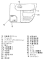
まず、図1乃至図7に基づいて、本発明の一実施形態について説明する。図1乃至図3において、自動車用ドアトリム10は、図示しないドアパネルの室内側にこれも図示しないクリップ等の固着手段を介して取り付けられており、ドアトリム10の表面略中央部には、乗員が肘を掛けて休めるようにアームレスト11が装着され、その上方の中接部のフロント側にインサイドハンドルエスカッション12が取り付けられ、かつドアトリム10の下部フロント側にスピーカグリル13が設けられている。更に、上記ドアトリム10のアームレスト11の下方には、各種備品、あるいは道路マップ等を収容できる射出成形品からなるドアポケット20が取り付けられている。
【0023】
このドアポケット20は、PP樹脂の射出成形体から構成されており、ドアトリム10に取り付けるには、要部ではないので図示は省略するが、ドアポケット20の裏面周縁部に沿って適宜ピッチ間隔で取付用ボスが立設され、ドアトリム10に上記取付用ボスに対応して開設されている取付孔に合致させて、ドアトリム10裏面側からビス等により固定するなどの慣用の固着手段を介して取り付けられている。
【0024】
ところで、本実施形態におけるドアポケット20は、上下2列に開口21(上部側開口21a、下部側開口21b)を有する射出成形品から構成され、良好なデザイン特性を備えるとともに、開口21の形状を考慮して、図2中符合Gで示す地点にゲートが設けられているものの、従来では、ゲートGから最遠隔地点に形成されるウエルドラインWが、本発明においては乗員から目立たないドアポケット20の下部側に設定されていることが特徴である。
【0025】
そして、ドアポケット20の下部側にウエルドラインWを形成するために、本実施形態では、上下2列の開口21a,21bのそれぞれの上部側に沿って開口21の長手方向に沿って延びる中空部22を備えた中空部構造が採用されている。尚、中空部22を形成するために、ガスインジェクション工法が使用されている。
【0026】
すなわち、図3に示すように、中空部22の外周部23は、奥行き寸法a×高さ寸法bが10mm×15mmに設定されており、ドアポケット20の射出成形時には、開口21の長手方向に沿って、外周部23の広い断面積(a×b寸法)が樹脂の流路面積となるため、この部分において樹脂流れが大幅に促進されることにより、ウエルドラインWがドアポケット20の下部側に形成されることになる。
【0027】
従って、この実施形態におけるドアポケット20においては、ガスインジェクション工法を使用した中空部22を開口21の長手方向に沿って設けたことで、ウエルドラインWを目立たないドアポケット20の下部側に変更することができる。
【0028】
よって、ウエルドラインWは、乗員から目立つことがないため、タッチアップ塗装等の2次加工を廃止でき、加工コストを低減できるとともに、中空部22構造であるため、熱収縮歪みが原因となる変形を有効に抑えることができ、しかも、製品表面にヒケ等が生じることがない。また、中空部22構造であるため、剛性も強化され、ドアを閉める際にドアポケット20を掴んで操作しても変形することがなく、使い勝手上も好ましい。
【0029】
次に、図4,図5に基づいて、ドアポケット20を成形する成形金型30の全体構成について、その概要を説明する。尚、この成形金型30は、左右のドアトリムに装着される左右対称状のドアポケット20を2個取りできる構造である。
【0030】
すなわち、図4に示すように、成形金型30は、固定側金型40と可動側金型50とから大略構成されている。固定側金型40は、固定側取付板41の下面に固定側型板42が取り付けられており、図4中ほぼ中央部に図示しない射出機から溶融樹脂を供給するためのマニホールド43が取り付けられている。
【0031】
一方、可動側金型50は、可動側取付板51にスペーサブロック52を介して可動側型板53が支持されており、固定側金型40と可動側金型50の型締め時、固定側型板42と可動側型板53間で画成されるキャビティC内に溶融樹脂が射出充填されることで、左右対称状のドアポケット20が所要形状に成形される。
【0032】
また、可動側金型50内には、スペーサブロック52で形成されるスペース内にエジェクタプレート54が内装されており、このエジェクタプレート54は、図示しないエジェクタプレート駆動シリンダにより所定ストローク上下動作を行ない、図4では図示するスプルロックピン55や図示しないエジェクタピンを突き上げることで成形後の成形品の脱型操作を円滑に行なうように機能する。更に、固定側型板42と可動側型板53との間に画成されるキャビティC内に供給される樹脂は、マニホールド43からスプル60、ランナ61、ゲート62を通じてキャビティC内に溶融樹脂が射出充填される。尚、可動側金型50は、可動側取付板51が図示しないプレスラムに連結され、このプレスラムの駆動により可動して、成形金型30の型締め、型開きが行なわれる。
【0033】
ところで、本実施形態におけるドアポケット20には、局部的に樹脂の流動性を高めるために、ガスインジェクション工法を利用した中空部22構造が採用されているが、この中空部22の形成手段としては、図5に示すように、ガス注入機構部70と、スピルアウト機構部80が設けられている。すなわち、スプル60、ランナ61、ゲート62を通じてキャビティC内に溶融樹脂が射出充填された後、ガス注入機構部70からガスが注入され、スピルアウト機構部80から余剰樹脂が排出されることで、中空部22が図5中点線で示す部分に形成される。
【0034】
次いで、本実施形態におけるドアポケット20において、中空部22を形成することにより、ウエルドラインWの形成位置を変更できる点について、図6,図7に基づいて説明する。図6は固定側金型40と可動側金型50との間に画成されるキャビティC内に射出充填される充填初期時の溶融樹脂の流れを示すもので、キャビティCの形状がドアポケット20の製品形状と対応するために、開口21a,21bで溶融樹脂は分岐した流れをとり、溶融樹脂の流れは(A)、(B)、(C)、(D)の4つの流れとなる。
【0035】
この場合、重要な流れは、(A)、(B)であり、この樹脂流れ(A)、(B)はそれぞれ奥行き寸法a×高さ寸法b=10mm×15mmの流路断面積を備えているため、溶融樹脂の充填初期時は、樹脂流れ(A)、(B)は開口21の長さ方向に沿って樹脂流れが著しく加速された状態となる。
【0036】
そして、図7に示すように、上部側の開口21aの長手方向端末付近で樹脂流れ(A)、(B)が合流するものの、これらは合流して更に下方向に向かうため、実質的にウエルドラインWは形成されない。そして、溶融樹脂の充填完了時には、キャビティCにおけるドアポケット20の下部において、樹脂流れ(A)、(B)と樹脂流れ(C)とが合流し、この合流地点にウエルドラインWが形成されることになる。
【0037】
このように、開口21a,21bの長手方向に沿って中空部22を形成する前段階では、この部分は、広い流路断面積を備えているため、樹脂流れ(A)、(B)は流動性が極めて高く、この樹脂の流動性を利用することで、ウエルドラインWを任意位置に制御することができる。
【0038】
従って、ドアポケット20の下部側にウエルドラインWを設定すれば、乗員の目に触れにくいため、ウエルドラインWを消すためのタッチアップ塗装等の2次加工が不要となり、加工工数を低減できる。
【0039】
次いで、図8,図9は、本発明をドアポケット20に適用した別の実施形態を示すもので、上述実施形態の中空部22に替えて、図8においては、成形品本体24の裏面に3条のリブ25が突設形成されている。従って、開口21に沿って裏面側にリブ25が条設されているため、この部分における樹脂の流動性が速まり、上述実施形態同様、上下の開口21a,21bの上方を流れる各樹脂流れは、下部側の開口21bの下側に廻り込み、この地点で樹脂流れが合流するため、ウエルドラインWを目立たない箇所に制御することができる。
【0040】
このように、図8に示すリブ25を形成したドアポケット20においても、上述したように、ウエルドラインWをドアポケット20の下部側に設定でき、ウエルドラインWが乗員の視線から目立たない箇所に設定できることから、タッチアップ塗装等の2次加工が不要となり、加工コストを低減化することができるとともに、リブ25により剛性が強化されているため、この部分を掴んでドアを閉めても、変形することがなく、優れた剛性を備えており、初期形状を長期に亘り維持することができる。
【0041】
更に、図9は、上下の開口21a,21bの長手方向に沿ってその上部側に厚肉部26を設定したドアポケット20であり、厚肉部26によりこの部分の樹脂の流動性が速められ、ウエルドラインWをドアポケット20の下部側に形成することで、タッチアップ塗装等の2次加工を不要とすることができる。尚、図9に示す厚肉部26を設ける構造では、収縮歪みが生じ易く、かつ重量化を伴なうという傾向はあるが、ガスインジェクション工法に使用するガス注入機構部、スピルアウト機構部が不要となり、かつリブ25を形成するための型加工が必要でないため、型設備、型加工が簡素化できるという利点がある。
【0042】
【発明の効果】
以上説明した通り、本発明によれば、開口を有する射出成形品及びその成形方法において、開口の長手方向に沿う両側のうち、少なくとも一方側にガスインジェクション工法による中空部構造、開口の長手方向に沿うリブの付設構造、厚肉部構造のいずれかを採用することで、一般部の樹脂流れに対して局部的に樹脂の流動性を速めることができ、従来、ゲートからの遠隔地点、という所定箇所に形成されるウエルドラインの形成位置を任意に制御することができ、目立たない部分にウエルドラインを設定することができるため、従来のようにウエルドラインを消すためのタッチアップ塗装等の2次加工が不要となり、加工コストを低減でき、コストダウンを招来できるという効果を有する。
【0043】
更に、ガスインジェクション工法による中空部構造を採用することで、樹脂の流動性を速めた場合には、中空部構造であるため、軽量でかつ熱収縮歪みが原因となる変形や製品表面にヒケ等が生じることがなく、しかも、剛性を強化できるという効果を有する。
【図面の簡単な説明】
【図1】本発明に係る射出成形品の一実施形態であるドアポケットを装着したドアトリムを示す正面図である。
【図2】本発明に係る射出成形品の一実施形態であるドアポケットを示す正面図である。
【図3】図2中III −III 線断面図である。
【図4】図2に示すドアポケットを成形するために使用する成形金型の全体構成を示す概要図である。
【図5】図4に示す成形金型における可動側金型のキャビティ部を示す平面図である。
【図6】図2に示すドアポケットの成形工程における樹脂充填初期時の樹脂流れを示す説明図である。
【図7】図2に示すドアポケットの成形工程における樹脂充填完了時の樹脂流れを示す説明図である。
【図8】本発明に係る射出成形品の別実施形態の構成を示す断面図である。
【図9】本発明に係る射出成形品の別実施形態の構成を示す断面図である。
【図10】従来の自動車用ドアトリムを示す正面図である。
【図11】従来のドアポケットを示す正面図である。
【図12】従来のドアポケットを示す正面図である。
【符号の説明】
10 自動車用ドアトリム
11 アームレスト
12 インサイドハンドルエスカッション
13 スピーカグリル
20 ドアポケット
21 開口
21a 上部側開口
21b 下部側開口
22 中空部
23 外周部
24 成形品本体
25 リブ
26 厚肉部
30 成形金型
40 固定側金型
42 固定側型板
50 可動側金型
53 可動側型板
60 スプル
61 ランナ
62 ゲート
70 ガス注入機構部
80 スピルアウト機構部
C キャビティ
W ウエルドライン[0001]
TECHNICAL FIELD OF THE INVENTION
INDUSTRIAL APPLICABILITY The present invention is applicable to interior parts for automobiles such as door pockets, rear pillar garnishes, etc., and relates to an injection molded product having an opening and a molding method thereof. The present invention relates to an injection-molded article having an opening capable of eliminating secondary processing and reducing product cost, and a molding method thereof.
[0002]
[Prior art]
2. Description of the Related Art Conventionally, as an automotive interior component to be installed in a vehicle, an injection molded product using a general-purpose resin such as a polypropylene (PP) resin is often used in consideration of cost, moldability, physical properties, and the like.
[0003]
For example, FIG. 10 shows an automobile door trim 1 mounted on the indoor side of a door panel of a vehicle. A
[0004]
Although not shown in the patent document, as shown in FIG. 12, a
[0005]
The gate position of the
[0006]
[Patent Document 1]
JP-A-10-244880 (page 3, FIG. 2, FIG. 3)
[0007]
[Problems to be solved by the invention]
As described above, conventionally, in an injection molded product such as the
[0008]
As a countermeasure, it has been pointed out that secondary processing such as touch-up painting is required so as to cover the weld line W, resulting in an increase in processing cost and an increase in product cost.
[0009]
This means that as shown in FIG. 12, when the two openings 3a and 3b are set up and down, the resin flow along the longitudinal direction of the opening 3 is branched into three with the two openings 3a and 3b interposed therebetween. Resin flow is obtained. Therefore, two weld lines W are formed from the right ends of the two openings 3a and 3b to the right end of the
[0010]
The present invention has been made in view of such circumstances, and eliminates secondary processing such as touch-up painting by controlling the formation of weld lines, which are inevitable, in an injection-molded article having an opening. It is an object of the present invention to provide an injection-molded article having an opening capable of reducing the production cost by doing so and a molding method therefor.
[0011]
[Means for Solving the Problems]
In order to solve the above problems, the present invention has an opening that is formed into a required shape by injecting and filling a molten resin into a cavity defined between a fixed mold and a movable mold. An injection-molded product, a resin flow promoting structure is adopted on at least one side of both sides along the longitudinal direction of the opening, so that a plurality of resin flows along the longitudinal direction of the opening across the opening merge. It is characterized in that the formation location of the weld line formed at the location where it is formed can be changed.
[0012]
Here, the injection molded product having an opening can be applied to a door pocket mounted on a door trim, a rear pillar garnish mounted around an opera window of a vehicle, and the like.
[0013]
Further, as the resin fluidity promoting structure, a hollow structure by a gas injection method, a structure provided with ribs, a thick-wall structure, or the like can be considered.
[0014]
According to the present invention, a hollow structure formed by a gas injection method on at least one of the two sides sandwiching the opening, a rib-attached structure having ribs extending along the longitudinal direction of the opening, or an increase in the thickness of the general portion. By adopting a thicker wall structure, the resin flow can be extremely accelerated.In the past, the weld line was inevitably formed at the farthest point from the gate, but it partially flowed. The position of the weld line can be changed by speeding up the process.
[0015]
Therefore, by locally accelerating the resin flow, a weld line can be set in a place where the occupant cannot easily see it, and in such a case, a secondary process such as touch-up painting for hiding the weld line can be omitted. .
[0016]
Further, when a hollow structure formed by a gas injection method is employed as the resin fluidity promoting structure, deformation and surface sink caused by heat shrinkage distortion can be prevented, and strong rigidity can be maintained.
[0017]
Next, in the method of molding an injection-molded article having an opening according to the present invention, the molten resin is injected and filled into a cavity defined between the fixed mold and the movable mold through a gate of the mold. A method for molding an injection-molded article having an opening for molding an injection-molded article having a required shape with an opening, wherein the gate is set at one side edge of the injection-molded article on the longitudinal end side of the opening; By setting the flow path cross-sectional area of at least one side of both sides along the longitudinal direction to be large, it is possible to prevent the resin flow from joining at the edge opposite to the gate at the opening and to adjust the flowability of the resin. , The position at which the weld line is formed is controlled.
[0018]
Here, the gate is set at a point extending from the longitudinal end of the opening to the terminal side of the injection molded article along the longitudinal direction of the opening so that the resin flows along the longitudinal direction of the opening.
[0019]
Therefore, according to the method for molding an injection-molded article having an opening according to the present invention, at least one side of both sides along the longitudinal direction of the opening has a flow path cross-sectional area in order to promote fluidity of the resin. Since it is set large, the formation position of the weld line formed at the point where the branched resin flows join can be changed to an arbitrary position by changing the cross-sectional area.
[0020]
BEST MODE FOR CARRYING OUT THE INVENTION
Hereinafter, a preferred embodiment of an injection-molded article having an opening according to the present invention and a molding method thereof will be described by exemplifying a door pocket mounted on a door trim.
[0021]
FIG. 1 is a front view showing a configuration of a door trim equipped with a door pocket to which the present invention is applied, FIG. 2 is a front view of the door pocket, FIG. 3 is a sectional view showing the configuration of the door pocket, and FIG. FIG. 5 is a schematic view showing the overall configuration of a molding die used in the molding method of FIG. 5, FIG. 5 is a plan view of a movable mold in the molding die, and FIG. FIG. 7 is an explanatory view showing the flow of resin when resin filling is completed in the molding process of the door pocket. FIGS. 8 and 9 are sectional views showing modified embodiments of the door pocket to which the present invention is applied. .
[0022]
First, an embodiment of the present invention will be described with reference to FIGS. 1 to 3, an automobile door trim 10 is attached to a room inside a door panel (not shown) via a fixing means such as a clip (not shown). An armrest 11 is mounted so as to rest on the inside, an
[0023]
The
[0024]
By the way, the
[0025]
In order to form a weld line W on the lower side of the
[0026]
That is, as shown in FIG. 3, the outer
[0027]
Therefore, in the
[0028]
Accordingly, since the weld line W is not noticeable by the occupant, secondary processing such as touch-up painting can be eliminated, and the processing cost can be reduced. In addition, since the weld line W has the
[0029]
Next, an outline of the overall configuration of the molding die 30 for molding the
[0030]
That is, as shown in FIG. 4, the molding die 30 is roughly composed of a fixed
[0031]
On the other hand, in the
[0032]
In the
[0033]
By the way, the
[0034]
Next, the point that the formation position of the weld line W can be changed by forming the
[0035]
In this case, the important flows are (A) and (B), and the resin flows (A) and (B) each have a channel cross-sectional area of depth dimension a × height dimension b = 10 mm × 15 mm. Therefore, at the initial stage of filling the molten resin, the resin flows (A) and (B) are in a state where the resin flow is remarkably accelerated along the length direction of the
[0036]
As shown in FIG. 7, although the resin flows (A) and (B) merge near the longitudinal end of the opening 21a on the upper side, they merge and go further downward, so that substantially the weld is formed. No line W is formed. When the filling of the molten resin is completed, the resin flows (A) and (B) and the resin flow (C) merge at the lower portion of the
[0037]
As described above, before the
[0038]
Therefore, if the weld line W is set on the lower side of the
[0039]
Next, FIGS. 8 and 9 show another embodiment in which the present invention is applied to a
[0040]
Thus, in the
[0041]
Further, FIG. 9 shows a
[0042]
【The invention's effect】
As described above, according to the present invention, in an injection-molded article having an opening and a method of molding the same, at least one of the two sides along the longitudinal direction of the opening has a hollow structure formed by a gas injection method, By adopting either the rib-attached structure along the wall or the thick-walled structure, it is possible to accelerate the fluidity of the resin locally with respect to the resin flow in the general part. It is possible to arbitrarily control the formation position of the weld line formed in the place, and to set the weld line in an inconspicuous part. There is an effect that the processing is not required, the processing cost can be reduced, and the cost can be reduced.
[0043]
Furthermore, when the fluidity of the resin is accelerated by adopting the hollow structure by the gas injection method, the hollow structure is lightweight, and it is lightweight and deforms due to heat shrinkage distortion, and sinks on the product surface. Is not generated, and the rigidity can be enhanced.
[Brief description of the drawings]
FIG. 1 is a front view showing a door trim equipped with a door pocket, which is one embodiment of an injection molded product according to the present invention.
FIG. 2 is a front view showing a door pocket which is an embodiment of the injection molded product according to the present invention.
FIG. 3 is a sectional view taken along line III-III in FIG. 2;
FIG. 4 is a schematic diagram showing the overall configuration of a molding die used to mold the door pocket shown in FIG.
5 is a plan view showing a cavity of a movable mold in the molding mold shown in FIG. 4;
FIG. 6 is an explanatory view showing a resin flow at an initial stage of resin filling in a door pocket forming step shown in FIG. 2;
FIG. 7 is an explanatory diagram showing a resin flow when resin filling is completed in a door pocket forming step shown in FIG. 2;
FIG. 8 is a cross-sectional view showing a configuration of another embodiment of the injection molded product according to the present invention.
FIG. 9 is a cross-sectional view showing a configuration of another embodiment of the injection molded product according to the present invention.
FIG. 10 is a front view showing a conventional automobile door trim.
FIG. 11 is a front view showing a conventional door pocket.
FIG. 12 is a front view showing a conventional door pocket.
[Explanation of symbols]
DESCRIPTION OF
Claims (5)
前記開口(21)の長手方向に沿う両側部のうち、少なくとも一方側に樹脂流動性促進構造を採用することで、開口(21)を挟んで開口(21)の長手方向に沿う複数の樹脂流れが合流する箇所に形成されるウエルドライン(W)の形成箇所を変更可能としたことを特徴とする開口を有する射出成形品。The cavity (C) defined between the fixed mold (40) and the movable mold (50) has an opening (21) formed into a required shape by injection filling with molten resin. An injection molded product (20),
By adopting a resin fluidity promoting structure on at least one side of both sides along the longitudinal direction of the opening (21), a plurality of resin flows along the longitudinal direction of the opening (21) across the opening (21). An injection-molded article having an opening, characterized in that a weld line (W) formed at a position where the two meet can be changed.
前記ゲート(62)を開口(21)の長手方向端末側の射出成形品(20)の一方側縁部に設定するとともに、開口(21)の長手方向に沿う両側部の少なくとも一方側の流路断面積を大きく設定することにより、開口(21)におけるゲート(62)反対側縁部での樹脂流れの合流を回避させるとともに、樹脂の流動性を調整することにより、ウエルドライン(W)の形成位置を制御することを特徴とする開口を有する射出成形品の成形方法。The molten resin is injected and filled into the cavity (C) defined between the fixed mold (40) and the movable mold (50) through the gate (62) of the molding mold (30). In a method for molding an injection molded product (20) having an opening (21) for molding an injection molded product (20) having a required shape having (21),
The gate (62) is set at one side edge of the injection molded product (20) on the terminal side in the longitudinal direction of the opening (21), and at least one of the flow paths on both sides along the longitudinal direction of the opening (21). By setting the cross-sectional area large, it is possible to prevent the resin flow from converging at the edge of the opening (21) opposite to the gate (62), and to form the weld line (W) by adjusting the flowability of the resin. A method for molding an injection-molded article having an opening, characterized by controlling a position.
Priority Applications (1)
| Application Number | Priority Date | Filing Date | Title |
|---|---|---|---|
| JP2002346175A JP2004175031A (en) | 2002-11-28 | 2002-11-28 | Injection-molded article with opening and method for molding it |
Applications Claiming Priority (1)
| Application Number | Priority Date | Filing Date | Title |
|---|---|---|---|
| JP2002346175A JP2004175031A (en) | 2002-11-28 | 2002-11-28 | Injection-molded article with opening and method for molding it |
Publications (1)
| Publication Number | Publication Date |
|---|---|
| JP2004175031A true JP2004175031A (en) | 2004-06-24 |
Family
ID=32707162
Family Applications (1)
| Application Number | Title | Priority Date | Filing Date |
|---|---|---|---|
| JP2002346175A Pending JP2004175031A (en) | 2002-11-28 | 2002-11-28 | Injection-molded article with opening and method for molding it |
Country Status (1)
| Country | Link |
|---|---|
| JP (1) | JP2004175031A (en) |
Cited By (6)
| Publication number | Priority date | Publication date | Assignee | Title |
|---|---|---|---|---|
| JP2013111857A (en) * | 2011-11-29 | 2013-06-10 | Toyota Boshoku Corp | Rib structure of molded structure |
| WO2014203617A1 (en) * | 2013-06-18 | 2014-12-24 | テイ・エス テック株式会社 | Interior trim member and manufacturing device therefor |
| JP2015050275A (en) * | 2013-08-30 | 2015-03-16 | 株式会社ケーヒン | Substrate housing case |
| WO2017075754A1 (en) * | 2015-11-03 | 2017-05-11 | Hewlett-Packard Development Company, L.P. | Mold, molding method and product produced through molding process |
| JPWO2018110646A1 (en) * | 2016-12-15 | 2019-10-24 | 住友化学株式会社 | Method for manufacturing plate-shaped body, mold and runner |
| JP2020097433A (en) * | 2018-12-18 | 2020-06-25 | 株式会社 ダイサン | Buffer |
-
2002
- 2002-11-28 JP JP2002346175A patent/JP2004175031A/en active Pending
Cited By (7)
| Publication number | Priority date | Publication date | Assignee | Title |
|---|---|---|---|---|
| JP2013111857A (en) * | 2011-11-29 | 2013-06-10 | Toyota Boshoku Corp | Rib structure of molded structure |
| WO2014203617A1 (en) * | 2013-06-18 | 2014-12-24 | テイ・エス テック株式会社 | Interior trim member and manufacturing device therefor |
| JP2015050275A (en) * | 2013-08-30 | 2015-03-16 | 株式会社ケーヒン | Substrate housing case |
| WO2017075754A1 (en) * | 2015-11-03 | 2017-05-11 | Hewlett-Packard Development Company, L.P. | Mold, molding method and product produced through molding process |
| JPWO2018110646A1 (en) * | 2016-12-15 | 2019-10-24 | 住友化学株式会社 | Method for manufacturing plate-shaped body, mold and runner |
| JP2020097433A (en) * | 2018-12-18 | 2020-06-25 | 株式会社 ダイサン | Buffer |
| JP7155493B2 (en) | 2018-12-18 | 2022-10-19 | 株式会社 ダイサン | buffer |
Similar Documents
| Publication | Publication Date | Title |
|---|---|---|
| US6838027B2 (en) | Method of making an interior trim panel | |
| US20030211311A1 (en) | Integrated co-injection molded vehicle components and methods of making the same | |
| US20200189664A1 (en) | Load bearing panel member | |
| US6171543B1 (en) | Rocker panel construction | |
| US5804117A (en) | Molding method for resin articles | |
| EP0630774B1 (en) | Resin panel with integrally molded hollow truss | |
| JP2008155395A (en) | Method and apparatus for molding laminated molding | |
| JP2004175031A (en) | Injection-molded article with opening and method for molding it | |
| JP4975313B2 (en) | Vehicle cowl top cover | |
| JP2009154428A (en) | Automobile interior component, and method for producing the same | |
| KR102161098B1 (en) | Hybrid panel for vehicle interior part with lightweight reinforcement structure | |
| US10596738B2 (en) | Method for producing a component assembly for a motor vehicle, component assembly for a motor vehicle, and motor vehicle having the component assembly | |
| JP4251443B2 (en) | Manufacturing method for interior parts for automobiles | |
| JP6539406B2 (en) | Resin molded article for vehicle and method for manufacturing resin molded article for vehicle | |
| JP4135917B2 (en) | Manufacturing method of automotive interior parts and molding die | |
| JP2009262499A (en) | Foamed resin molded article and its molding process | |
| JP3203870B2 (en) | Method of manufacturing resin products | |
| JP2008006620A (en) | Automotive interior trim and its manufacturing method | |
| JP2009262433A (en) | Molding method of foamed resin molded product | |
| EP1112831A1 (en) | Method of making an interior trim panel | |
| JP2005329544A (en) | Two-color molded product and its molding method | |
| JP2019142078A (en) | Manufacturing method of molded structure | |
| JP2011000788A (en) | Foamed resin molded article and method for molding the same | |
| JP2008142919A (en) | Molding method of multicolor molded product | |
| JP5013474B2 (en) | Foamed resin molded product |
Legal Events
| Date | Code | Title | Description |
|---|---|---|---|
| A621 | Written request for application examination |
Effective date: 20050602 Free format text: JAPANESE INTERMEDIATE CODE: A621 |
|
| A977 | Report on retrieval |
Free format text: JAPANESE INTERMEDIATE CODE: A971007 Effective date: 20061226 |
|
| A131 | Notification of reasons for refusal |
Effective date: 20070105 Free format text: JAPANESE INTERMEDIATE CODE: A131 |
|
| A02 | Decision of refusal |
Effective date: 20070425 Free format text: JAPANESE INTERMEDIATE CODE: A02 |