JP2004169999A - Incineration/melting furnace - Google Patents
Incineration/melting furnace Download PDFInfo
- Publication number
- JP2004169999A JP2004169999A JP2002336610A JP2002336610A JP2004169999A JP 2004169999 A JP2004169999 A JP 2004169999A JP 2002336610 A JP2002336610 A JP 2002336610A JP 2002336610 A JP2002336610 A JP 2002336610A JP 2004169999 A JP2004169999 A JP 2004169999A
- Authority
- JP
- Japan
- Prior art keywords
- incineration
- combustion chamber
- melting furnace
- water
- furnace
- Prior art date
- Legal status (The legal status is an assumption and is not a legal conclusion. Google has not performed a legal analysis and makes no representation as to the accuracy of the status listed.)
- Pending
Links
Images

Landscapes
- Incineration Of Waste (AREA)
- Gasification And Melting Of Waste (AREA)
Abstract
Description
【0001】
【発明の属する技術分野】
本発明は、ロストル下方の燃焼室において廃棄物を燃料として焼却処理しながら、発生した燃焼ガスを加熱して上方の燃焼室に送ることにより、ロストル上に投入された焼却物、汚染土壌、焼却残渣、金属類、汚泥等の廃棄物を焼却・溶融して無害化する焼却・溶融炉に関する。
【0002】
【従来の技術】
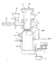
従来、この種の焼却・溶融炉は、図3のように構成されている。この炉では、、炉内中程に水冷ロストル1が配設され、その上に耐火物(セラミックボール)の充填層2が形成されている。この耐火物充填層2は、熱伝導のためと焼却物のロストル1からの落下を防止するためのものである。なお、3はスラグストッパー装置、4はスラグの取り出し口、5は廃棄プラスチックと空気の供給口、6は酸素の注入口、7は昇温用のオイルバーナ、8は水冷羽口、9は二重ダンパを備えた処理物の投入口、10は廃ガスの出口、11はスラグ鍋である。
【0003】
【発明が解決しようとする課題】
しかしながら、この焼却・溶融炉には、次のような問題があった。
(1)耐火物充填層は消耗が激しく、焼却物の3%の量を常時補給し続けなければならずランニングコストが嵩む。
(2)耐火物に含まれるアルミナ(Al2O3) がスラグに溶け込むことにより
、スラグの粘度が上昇して流動性が悪くなるとともに、スラグの量が多くなる。
(3)炉の径が大きくなると、充填層の厚みが不均一となり、吹き抜けが発生しやすく、燃焼が安定しない。
(4)充填層の密度が一定でないため圧力損失が大きくなり、静圧の大きい送風機が必要になる。
(5)炉頂から焼却物を投入するので、そのまま投入すると焼却物が炉壁にブリッジを形成する。そのため、焼却物を塊成するための前処理成形ラインを必要とした。
(6)同じく炉頂から焼却物を投入するので、最初の投入時には落差が大きくなり、ロストルおよび耐火物充填層がその衝撃により破損されることがあった。
【0004】
【課題を解決するための手段】
上記課題を解決するために、請求項1の発明は、炉内に水冷ロストルを配置しその下部の燃焼室で高温燃焼ガスを発生して上部の燃焼室へ送りその上部燃焼室に投入された焼却物を燃焼させる焼却・溶融炉において、前記水冷ロストルの配置を断面が千鳥配列となるようにして2段以上配置したことを特徴とする。
【0005】
請求項2の発明は、請求項1の発明において、前記水冷ロストルの位置よりも上の炉壁に焼却物の投入口を設けたことを特徴とする。
【0006】
請求項3の発明は、請求項1または2の発明において、前記焼却物の投入口の下方および上方の炉壁にそれぞれ燃焼空気供給口を設けたことを特徴とする。
【0007】
請求項4の発明は、請求項1乃至3のいずれかの発明において、前記下部燃焼室へ燃焼空気を供給する電動送風機をインバータ制御したことを特徴とする。
【0008】
請求項5の発明は、請求項1乃至4のいずれかの発明において、前記下部燃焼室に供給される燃料に可燃廃棄物を含むことを特徴とする。
【0009】
請求項6の発明は、請求項1乃至5のいずれかの発明において、前記下部燃焼室から上部燃焼室へ送られる高温燃焼ガスの温度を1500°C以上としたことを特徴とする。
【0010】
【発明の実施の形態】
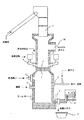
以下、図に基づいて本発明の実施形態を説明する。図1は本発明に係る焼却・溶融炉の構造図である。炉20の中程に、水冷ロストル1が、断面を千鳥の配列にして2段配設されている。この水冷ロストル1は3段以上に配置することも可能である。水冷ロストル1の下側に下部燃焼室21が形成され、水冷ロストル1の上側に上部燃焼室22が形成されている。下部燃焼室21には、供給口5から廃棄プラスチックと空気と酸素が供給されて燃焼されるとともに、昇温用のオイルバーナ7からオイルが供給されて燃焼される。
【0011】
さらに、必要な場合は、注入口6からも廃棄プラスチックと空気と酸素が注入される。なお、供給口5からは、廃棄プラスチックの他、廃油、紙屑、木屑等の廃棄物燃料が供給される。固形の廃棄物燃料は、破砕して空気輸送により下部燃焼室21へ送る。また、供給口5からの空気供給に用いる電動送風機は、インバータ制御することにより、送風量と圧力を連続的に制御することができる。他の部分の送風機も同様とする。これらの燃焼により、下部燃焼室21内で加熱されて1500°C以上となった燃焼ガスは、水冷ロストル1の隙間を通過して上部燃焼室22へ送られる。
【0012】
上部燃焼室22の側面には、焼却物の投入口23が設けられ、ホッパ24に投入された焼却物が、二重ダンパ25を経て落下すると、エアシリンダ26に駆動されるプッシャ27により、投入口23から上部燃焼室22内へ押し出される。なお、この投入口23は炉20の径が大きい場合は、両側に設けても良い。また、投入口23の下方のレベルには、一次燃焼空気供給口28が設けられ、投入口23の上方のレベルには、二次燃焼空気供給口29が設けられて、空気が供給される。また、焼却物としては、汚染土壌、焼却残渣、汚泥等が焼却可能である。
【0013】
上部燃焼室22内へ押し出された焼却物は、水冷ロストル1の上に落下して保持され、下方から供給された1500°C以上の燃焼ガスにより、加熱・焼却されて、水冷ロストル1の上には焼却溶融物が残る。この焼却溶融物は更に加熱されて、一部はガス化し、一次燃焼空気供給口28および二次燃焼空気供給口29からの空気供給により、完全燃焼する。残りの焼却溶融物は、溶融滴下し、下部燃焼室21へ落下する。ここで、一次燃焼空気供給口28および二次燃焼空気供給口29からの供給空気を酸素富化すると、より高温の燃焼が可能となる。
【0014】
このように、上部燃焼室22内は、下部燃焼室21から1500°C以上の高温の燃焼ガスが供給されるとともに、さらに、上部燃焼室22内で空気を供給しながら焼却物を燃焼することにより、高温燃焼が可能となり、燃焼中に発生したダイオキシンも完全分解されてから出口10より排出される。また、上部燃焼室22内で酸素を富化して高温燃焼されるため、排ガス量が減り、CO2も削減される。なお、下部燃焼室21へ落下したスラグは、スラグストッパー装置3を作動させて取り出し口4から排出されてスラグ鍋11に取り出され、路盤材料等に再利用される。
【0015】
図2は、図1の水冷ロストル1を拡大して示した断面図である。水冷ロストル1には、水平方向両側にフィン1a,1bが形成されている。このように水冷ロストル1を等間隔で交互にして他段に配設したことで、溶湯に熱伝導効果が得られる。また、水冷ロストル1の間隔が一定であるため、水冷ロストル1の間を通過する燃焼ガスの圧力損失が各部で均一となり、下部燃焼室21への空気供給の送風機は、静圧の低い送風機で充分となり、加えてインバータ制御することで動力の節電となる。なお、水冷ロストル1は、腐食防止のため、各種金属または耐火物によりライニングすると良い。
【0016】
このように、本発明の焼却・溶融炉は、水冷ロストル1を等間隔で交互にして多段に配設し、水冷ロストル1のやや上のレベルの炉壁に焼却物の投入口23を設けて、投入口23から水冷ロストル1の上に焼却物を直接投下しても、焼却物が水冷ロストル1の下方に落下することがないようにしたことで、従来のように水冷ロストル1上に耐火物充填層を形成する必要がなくなり、耐火物が不要になった分、ランニングコストが低減される。しかも、耐火物を投入しなくなったのでスラグにアルミナが混入しないため、スラグの流動性が損なわれず、またスラグの量が増えることもない。
【0017】
また、焼却物を炉頂からでなく、投入口23から投入するようにしたため、従来必要であったブリッジの発生を防止するために焼却物を塊成化する前工程(前処理ライン)が不要になる。同時に、投入時の水冷ロストル1へ加わる焼却物からの衝撃も弱められ、水冷ロストル1の寿命も伸びる。
【0018】
【発明の効果】
以上述べたように請求項1の発明によれば、水冷ロストルの配置を断面が千鳥配列となるようにして2段以上配置したことで、ロストルの間からの焼却物落下がなくなるため、耐火物充填層を形成する必要がなくなり、ランニングコストが低減される。また、耐火物を投入しないため、スラグの粘度が上昇しなくなり流動性が改善されるとともに、スラグの量も少なくなる。さらには、耐火物充填層がなくなるため、吹き抜けの発生がなくなり燃焼が安定するとともに、送風機の静圧を大きくする必要がなくなる。しかもロストルを多段にしたことで溶湯に熱伝導効果がある。
【0019】
請求項2の発明によれば、前記水冷ロストルの位置よりも上の炉壁に、焼却物の投入口を設けたことで、炉頂から焼却物が投入されないため、炉壁にブリッジが形成されることがなくなり、塊成化の前工程が不要になるとともに、水冷ロストルへの衝撃がなくなり水冷ロストルの寿命が長くなる。
請求項3の発明によれば、前記焼却物の投入口の下方および上方の炉壁にそれぞれ燃焼空気供給口を設けたことで、上部燃焼室内での焼却物の完全燃焼が可能となる。
【0020】
請求項4の発明によれば、下部燃焼室へ燃焼空気を供給する電動送風機をインバータ制御したことで、上部燃焼室の燃焼状態に応じて、下部燃焼室への燃焼空気の供給量を連続的に調整することが可能となるとともに、電動送風機の省エネにもなる。
請求項5の発明によれば、下部燃焼室に供給される燃料に可燃廃棄物を含むことで、燃料の節約をすることが可能となる。
請求項6の発明によれば、下部燃焼室から上部燃焼室へ送られる高温燃焼ガスの温度を1500°C以上としたことで、焼却物が完全燃焼して無害化され、ダイオキシンの発生も防止できる。
【図面の簡単な説明】
【図1】本発明に係る焼却・溶融炉の構造図である。
【図2】図1の水冷ロストルを拡大して示した断面図である。
【図3】従来の焼却・溶融炉の構造図である。
【符号の説明】
1 水冷ロストル
1a,1b フィン
3 スラグストッパー装置
4 取り出し口
5 供給口
6 注入口
7 オイルバーナ
10 出口
11 スラグ鍋
20 炉
21 下部燃焼室
22 上部燃焼室
23 投入口
24 ホッパ
25 二重ダンパ
26 エアシリンダ
27 プッシャ
28 一次燃焼空気供給口
29 二次燃焼空気供給口[0001]
TECHNICAL FIELD OF THE INVENTION
The present invention heats generated combustion gas and sends it to an upper combustion chamber while incinerating waste as a fuel in a combustion chamber below the roster, so that incinerated material, contaminated soil, The present invention relates to an incineration / melting furnace that incinerates and melts waste such as residues, metals, and sludge.
[0002]
[Prior art]
Conventionally, this kind of incineration / melting furnace is configured as shown in FIG. In this furnace, a water-cooled roaster 1 is provided in the middle of the furnace, and a refractory (ceramic ball) filling layer 2 is formed thereon. The refractory filled layer 2 is for heat conduction and for preventing the incinerated material from dropping from the rostral 1. 3 is a slag stopper device, 4 is a slag outlet, 5 is a supply port of waste plastic and air, 6 is an oxygen inlet, 7 is an oil burner for increasing temperature, 8 is a water cooling tuyere, and 9 is An inlet for a processed material provided with a heavy damper, an outlet for waste gas 10, and a slag pot 11 are provided.
[0003]
[Problems to be solved by the invention]
However, this incineration / melting furnace has the following problems.
(1) The refractory packed bed is severely consumed, and 3% of the incinerated material must be constantly replenished, increasing running costs.
(2) As alumina (Al2O3) contained in the refractory melts into the slag, the viscosity of the slag increases, the fluidity deteriorates, and the amount of the slag increases.
(3) If the diameter of the furnace is large, the thickness of the packed bed is not uniform, so that blow-through easily occurs and combustion is not stable.
(4) Since the density of the packed bed is not constant, the pressure loss increases, and a blower with a large static pressure is required.
(5) Since the incinerated material is introduced from the furnace top, if it is introduced as it is, the incinerated material forms a bridge on the furnace wall. Therefore, a pretreatment molding line for agglomerating the incinerated material was required.
(6) Since the incinerated material is also charged from the top of the furnace, the drop is large at the first charging, and the rostr and the refractory packed layer may be damaged by the impact.
[0004]
[Means for Solving the Problems]
In order to solve the above-mentioned problem, in the invention of claim 1, a water-cooled roaster is arranged in a furnace, a high-temperature combustion gas is generated in a lower combustion chamber, sent to an upper combustion chamber, and injected into the upper combustion chamber. In an incineration / melting furnace for burning incineration, the water-cooled roaster is arranged in two or more stages in a staggered cross section.
[0005]
A second aspect of the present invention is characterized in that, in the first aspect of the present invention, an inlet for incinerated material is provided in a furnace wall above a position of the water-cooled roaster.
[0006]
The invention of
[0007]
According to a fourth aspect of the present invention, in any one of the first to third aspects, an electric blower for supplying combustion air to the lower combustion chamber is inverter-controlled.
[0008]
According to a fifth aspect of the present invention, in any one of the first to fourth aspects, the fuel supplied to the lower combustion chamber contains combustible waste.
[0009]
According to a sixth aspect of the present invention, in any one of the first to fifth aspects, the temperature of the high-temperature combustion gas sent from the lower combustion chamber to the upper combustion chamber is 1500 ° C. or more.
[0010]
BEST MODE FOR CARRYING OUT THE INVENTION
Hereinafter, embodiments of the present invention will be described with reference to the drawings. FIG. 1 is a structural diagram of an incineration / melting furnace according to the present invention. In the middle of the
[0011]
Further, if necessary, waste plastic, air and oxygen are injected from the injection port 6. In addition, waste fuel such as waste oil, paper waste, wood waste, etc. is supplied from the supply port 5 in addition to waste plastic. The solid waste fuel is crushed and sent to the lower combustion chamber 21 by pneumatic transportation. In addition, the electric blower used for supplying air from the supply port 5 can continuously control the blowing amount and the pressure by performing inverter control. The same applies to the other parts of the blower. The combustion gas heated in the lower combustion chamber 21 to 1500 ° C. or higher by these combustions is sent to the
[0012]
On the side surface of the
[0013]
The incinerated material extruded into the
[0014]
As described above, the inside of the
[0015]
FIG. 2 is an enlarged sectional view of the water-cooled roaster 1 of FIG. The water-cooled roaster 1 has
[0016]
Thus, in the incineration / melting furnace of the present invention, the water-cooled roasters 1 are alternately arranged at equal intervals in multiple stages, and the incineration material inlet 23 is provided in the furnace wall at a level slightly above the water-cooled roaster 1. Even when the incinerated material is dropped directly onto the water-cooled roaster 1 from the inlet 23, the incinerated material is prevented from falling below the water-cooled roaster 1, so that the fire-resistant material is refractory onto the water-cooled roaster 1 as in the prior art. There is no need to form a material-filled layer, and running costs are reduced by the amount that refractories are no longer necessary. In addition, since the refractory is no longer introduced, no alumina is mixed into the slag, so that the fluidity of the slag is not impaired and the amount of the slag does not increase.
[0017]
In addition, since the incinerated material is introduced from the inlet 23 instead of from the furnace top, a pre-process (pretreatment line) for agglomerating the incinerated material, which is conventionally required, is prevented in order to prevent the occurrence of a bridge. become. At the same time, the impact from the incinerated material applied to the water-cooled roaster 1 at the time of charging is reduced, and the life of the water-cooled roaster 1 is extended.
[0018]
【The invention's effect】
As described above, according to the first aspect of the present invention, since the water-cooled roaster is arranged in two or more stages so that the cross section has a staggered arrangement, the incineration material does not fall from between the rostles. There is no need to form a packed layer, and running costs are reduced. In addition, since the refractory is not charged, the viscosity of the slag does not increase, the flowability is improved, and the amount of the slag is reduced. Furthermore, since there is no refractory filled layer, blow-through does not occur and combustion is stabilized, and it is not necessary to increase the static pressure of the blower. Moreover, the molten metal has a heat conduction effect due to the multi-stage rostral.
[0019]
According to the invention of claim 2, since the incinerated material is provided at the inlet of the furnace wall above the position of the water-cooled roster, the incinerated material is not injected from the furnace top, so that a bridge is formed on the furnace wall. This eliminates the need for a previous step of agglomeration and eliminates the impact on the water-cooled rostr.
According to the third aspect of the present invention, the combustion air supply ports are provided in the furnace wall below and above the incineration material inlet, respectively, so that the incineration material can be completely burned in the upper combustion chamber.
[0020]
According to the fourth aspect of the present invention, the electric blower that supplies the combustion air to the lower combustion chamber is inverter-controlled, so that the supply amount of the combustion air to the lower combustion chamber is continuously changed according to the combustion state of the upper combustion chamber. And the energy consumption of the electric blower can be reduced.
According to the fifth aspect of the present invention, the fuel supplied to the lower combustion chamber contains combustible waste, so that fuel can be saved.
According to the invention of claim 6, by setting the temperature of the high-temperature combustion gas sent from the lower combustion chamber to the upper combustion chamber to 1500 ° C. or more, the incinerated material is completely burned and rendered harmless, and the generation of dioxin is also prevented. it can.
[Brief description of the drawings]
FIG. 1 is a structural diagram of an incineration / melting furnace according to the present invention.
FIG. 2 is an enlarged cross-sectional view of the water-cooled roaster of FIG.
FIG. 3 is a structural view of a conventional incineration / melting furnace.
[Explanation of symbols]
DESCRIPTION OF SYMBOLS 1 Water-cooled
Claims (6)
前記水冷ロストルの配置を断面が千鳥配列となるようにして2段以上配置したことを特徴とする焼却・溶融炉。In an incineration / melting furnace that arranges a water-cooled roster in the furnace, generates high-temperature combustion gas in the lower combustion chamber, sends it to the upper combustion chamber, and burns the incineration material injected into the upper combustion chamber,
The incineration / melting furnace, wherein the water-cooled roaster is arranged in two or more stages so that the cross section is staggered.
前記水冷ロストルの位置よりも上の炉壁に焼却物の投入口を設けたことを特徴とする焼却・溶融炉。The incineration / melting furnace according to claim 1,
An incineration / melting furnace, wherein an inlet for incineration material is provided in a furnace wall above the position of the water-cooled roaster.
前記焼却物の投入口の下方および上方の炉壁にそれぞれ燃焼空気供給口を設けたことを特徴とする焼却・溶融炉。The incineration / melting furnace according to claim 1 or 2,
An incineration / melting furnace, wherein combustion air supply ports are provided in furnace walls below and above the incineration material inlet, respectively.
前記下部燃焼室へ燃焼空気を供給する電動送風機をインバータ制御したことを特徴とする焼却・溶融炉。The incineration / melting furnace according to any one of claims 1 to 3,
An incineration / melting furnace, wherein an electric blower for supplying combustion air to the lower combustion chamber is inverter-controlled.
前記下部燃焼室に供給される燃料に可燃廃棄物を含むことを特徴とする焼却・溶融炉。In the incineration / melting furnace according to any one of claims 1 to 4,
The incineration / melting furnace characterized in that the fuel supplied to the lower combustion chamber contains combustible waste.
前記下部燃焼室から上部燃焼室へ送られる高温燃焼ガスの温度を1500°C以上としたことを特徴とする焼却・溶融炉。The incineration / melting furnace according to any one of claims 1 to 5,
An incineration / melting furnace, wherein the temperature of the high-temperature combustion gas sent from the lower combustion chamber to the upper combustion chamber is 1500 ° C. or higher.
Priority Applications (1)
| Application Number | Priority Date | Filing Date | Title |
|---|---|---|---|
| JP2002336610A JP2004169999A (en) | 2002-11-20 | 2002-11-20 | Incineration/melting furnace |
Applications Claiming Priority (1)
| Application Number | Priority Date | Filing Date | Title |
|---|---|---|---|
| JP2002336610A JP2004169999A (en) | 2002-11-20 | 2002-11-20 | Incineration/melting furnace |
Publications (1)
| Publication Number | Publication Date |
|---|---|
| JP2004169999A true JP2004169999A (en) | 2004-06-17 |
Family
ID=32700397
Family Applications (1)
| Application Number | Title | Priority Date | Filing Date |
|---|---|---|---|
| JP2002336610A Pending JP2004169999A (en) | 2002-11-20 | 2002-11-20 | Incineration/melting furnace |
Country Status (1)
| Country | Link |
|---|---|
| JP (1) | JP2004169999A (en) |
Cited By (3)
| Publication number | Priority date | Publication date | Assignee | Title |
|---|---|---|---|---|
| JP2010145049A (en) * | 2008-12-19 | 2010-07-01 | Nippon Steel Engineering Co Ltd | Dust discharging device of high temperature furnace |
| CN112830653A (en) * | 2021-01-20 | 2021-05-25 | 北京博霖环境科技有限公司 | Multistage distributed feeding pyrolysis device for high-liquid-content oil sludge |
| CN112830654A (en) * | 2021-01-20 | 2021-05-25 | 北京博霖环境科技有限公司 | High liquid fatlute distributing type feeding pyrolysis device that contains |
-
2002
- 2002-11-20 JP JP2002336610A patent/JP2004169999A/en active Pending
Cited By (5)
| Publication number | Priority date | Publication date | Assignee | Title |
|---|---|---|---|---|
| JP2010145049A (en) * | 2008-12-19 | 2010-07-01 | Nippon Steel Engineering Co Ltd | Dust discharging device of high temperature furnace |
| CN112830653A (en) * | 2021-01-20 | 2021-05-25 | 北京博霖环境科技有限公司 | Multistage distributed feeding pyrolysis device for high-liquid-content oil sludge |
| CN112830654A (en) * | 2021-01-20 | 2021-05-25 | 北京博霖环境科技有限公司 | High liquid fatlute distributing type feeding pyrolysis device that contains |
| CN112830654B (en) * | 2021-01-20 | 2022-06-10 | 北京博霖环境科技有限公司 | High liquid fatlute distributing type feeding pyrolysis device that contains |
| CN112830653B (en) * | 2021-01-20 | 2022-06-14 | 北京博霖环境科技有限公司 | Multistage distributed feeding pyrolysis device for high-liquid-content oil sludge |
Similar Documents
| Publication | Publication Date | Title |
|---|---|---|
| KR100763531B1 (en) | Method for incineration disposal of waste | |
| TWI468626B (en) | A method of air for combustion of a vertical incinerator, and a vertical waste incinerator | |
| JP3034467B2 (en) | Direct-type incineration ash melting treatment equipment and treatment method | |
| JP2006349218A (en) | Slag basicity adjusting method and its device for gasification melting furnace | |
| JP2001227714A (en) | Method for incinerating disposal of waste | |
| JP4116698B2 (en) | Ash fusion incineration system | |
| JP2004169999A (en) | Incineration/melting furnace | |
| EP1227278A2 (en) | Waste treatment apparatus | |
| JP3904379B2 (en) | Dust discharge device for secondary combustion chamber | |
| TW505765B (en) | Ash melting apparatus | |
| JPS6033418A (en) | Disposal device for incinerating slag | |
| JP2005308231A (en) | Waste melting furnace and method of blowing gas therein | |
| JP2006029678A (en) | Heat insulation method when stopping supply of waste material in fluidized bed type gasified melting furnace | |
| JP3628163B2 (en) | Combustion ash melting furnace | |
| JP2007271206A (en) | Operation control method of gasification melting system, and system | |
| JPH05296425A (en) | Waste material melting furnace | |
| JPH08178239A (en) | Melting furnace | |
| JP2007085562A (en) | Shaft furnace type gasification melting furnace | |
| JP2001221414A (en) | Combustion method for combustion melting furnace, combustion melting furnace and waste combustion melting system provided with the same | |
| JP3611348B2 (en) | Electric melting furnace | |
| JP2008032361A (en) | Melting furnace | |
| KR200355318Y1 (en) | Brown gas high temperature pyrolysis melting incinerator | |
| JPS6033420A (en) | Disposal device for incineration slag | |
| JP2006010199A (en) | Melting treatment method of waste | |
| JP2000074352A (en) | Internal melting furnace for waste incineration apparatus |