JP2004160263A - Roentgenography apparatus - Google Patents

Roentgenography apparatus Download PDF

Info

Publication number
JP2004160263A
JP2004160263A JP2004070822A JP2004070822A JP2004160263A JP 2004160263 A JP2004160263 A JP 2004160263A JP 2004070822 A JP2004070822 A JP 2004070822A JP 2004070822 A JP2004070822 A JP 2004070822A JP 2004160263 A JP2004160263 A JP 2004160263A
Authority
JP
Japan
Prior art keywords
bed
imaging apparatus
ray
ray imaging
longitudinal direction
Prior art date
Legal status (The legal status is an assumption and is not a legal conclusion. Google has not performed a legal analysis and makes no representation as to the accuracy of the status listed.)
Granted
Application number
JP2004070822A
Other languages
Japanese (ja)
Other versions
JP3908228B2 (en
Inventor
Toshio Tate
外志雄 舘
Akio Hara
昭夫 原
Seiji Kamimura
成自 神村
Mitsuru Onuma
満 大沼
Isamu Takekoshi
勇 竹越
Current Assignee (The listed assignees may be inaccurate. Google has not performed a legal analysis and makes no representation or warranty as to the accuracy of the list.)
Hitachi Healthcare Manufacturing Ltd
Original Assignee
Hitachi Medical Corp
Priority date (The priority date is an assumption and is not a legal conclusion. Google has not performed a legal analysis and makes no representation as to the accuracy of the date listed.)
Filing date
Publication date
Application filed by Hitachi Medical Corp filed Critical Hitachi Medical Corp
Priority to JP2004070822A priority Critical patent/JP3908228B2/en
Publication of JP2004160263A publication Critical patent/JP2004160263A/en
Application granted granted Critical
Publication of JP3908228B2 publication Critical patent/JP3908228B2/en
Anticipated expiration legal-status Critical
Expired - Fee Related legal-status Critical Current

Links

Images

Abstract

<P>PROBLEM TO BE SOLVED: To provide a roentgenography apparatus, preferable for use in roentgenography while a doctor performs curing, and positioning a patient in a height to easily work according to the curing contents. <P>SOLUTION: This roentgenography apparatus is composed of: a table 12 of a bed 10 where the patient is placed; a table support device 60 having a function of inclining the table by a shaft right-angled in the longitudinal direction of the bed and moving up and down the table; an X-ray radiation device 250 located at a distance from the upper surface of the table above the patient side of the bed; and an X-ray detector 160 located below the table. The support device 60 has a lateral support supporting the bed from the side of the bed and a vertical support mechanism for moving up and down the lateral support, and the vertical support mechanism is disposed on one side of the bed and is positioned closely to the end part from the center in the longitudinal direction of the bed. The roentgenography apparatus secures a space for installing another treatment appliance without obstructing the movement and the curing work of a doctor in the periphery of the bed for curing the upper half body of a person (the patient). <P>COPYRIGHT: (C)2004,JPO

Description

本発明は、X線撮影装置に係り、特に、ベッドの周囲における医師の移動、治療を妨げることのないX線撮影装置に関する。   The present invention relates to an X-ray imaging apparatus, and more particularly to an X-ray imaging apparatus that does not hinder movement and treatment of a doctor around a bed.

従来のX線撮影装置は病気の早期発見などを目的とした撮影に使用されてきた。医学の進歩とともに単に診断を行うのみならず、治療中に撮影を行う要求が強まりこれに答えることが必要となってきた。   Conventional X-ray imaging apparatuses have been used for imaging for the purpose of early detection of diseases and the like. With the advancement of medicine, the demand for not only making a diagnosis but also taking a picture during treatment has increased, and it has become necessary to respond to this.

従来、治療中にX線撮影を行うという要求に対して、効率的に治療と撮影とを同時に行うことができる装置は知られていない。   Conventionally, there is no known device that can efficiently perform treatment and imaging at the same time in response to a request to perform X-ray imaging during treatment.

本発明の目的は、医者が治療を行いながらX線撮影を行なうに適しているX線撮影装置を提供することである。   An object of the present invention is to provide an X-ray imaging apparatus which is suitable for a doctor to perform X-ray imaging while performing treatment.

本発明の他の目的は、治療内容に応じて作業し易い高さに患者を位置させることができるX線撮影装置を提供することである。   Another object of the present invention is to provide an X-ray imaging apparatus capable of positioning a patient at a height at which work can be easily performed according to the treatment content.

本発明の一つであるX線撮影装置では、被検者を乗せるベッドのテーブルと、ベッドの長手方向に対し直角方向の軸でテーブルを傾斜させるとともにテーブルを上下させる機能を有するテーブル支持装置と、ベッドの被検者側上部にテーブル上面から距離を置いて位置するX線照射装置と、テーブルの下部に位置するX線像撮像装置とからなり、前記支持装置が、ベッドの側部からテーブルを支持する横支持体と前記横支持体を上下させる縦支持機構を有し、前記支持装置が、ベッドの長手方向の一端側で前記テーブルを支持し、前記X線像撮像装置が、ベッドの長手方向の他端側の底面に取り付けられていることを特徴とする。これによりベッド支持装置が治療の邪魔をするのを押さえることができる。   In an X-ray imaging apparatus according to one aspect of the present invention, there is provided a table of a bed on which a subject is placed, and a table support device having a function of tilting the table about an axis perpendicular to the longitudinal direction of the bed and moving the table up and down. An X-ray irradiator positioned above the bed at a distance from the upper surface of the subject, and an X-ray imaging device positioned below the table. A vertical support mechanism for supporting the table and supporting the table at one end in the longitudinal direction of the bed, and the X-ray imaging apparatus includes: It is characterized in that it is attached to the bottom surface at the other end in the longitudinal direction. This can prevent the bed support device from interfering with the treatment.

本発明によれば、ベッドの縦支持機構がベッドの一方の側でしかもベッドの長手方向の中心より端部側に、例えば、被治療者の足元側に配置されているので、被治療者の上半身のベッド周囲における医師の移動、治療作業の妨げにならず、また、他の治療器具を設置するスペースを確保することができる。   According to the present invention, since the vertical support mechanism of the bed is arranged on one side of the bed and on the end side from the center in the longitudinal direction of the bed, for example, at the foot side of the patient, The movement of the doctor around the upper body bed and the treatment work are not hindered, and the space for installing other treatment instruments can be secured.

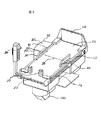
図1は本発明の一実施形態である二方向透視撮影機能を有するX線撮影装置を示す。図2はベッド10の拡大図である。被検者を乗せるベッド10のテーブル12は天板14を有し、この天板14はX線を透過する材質で作られている。天板14から所定の距離を置いて、天井6から釣下げられたX線照射装置250が配置されている。一方テーブル12の下側には被検者を通過したX線を検知するX線検知手段160が設けられ、X線像を撮影する。上記検知手段160によりX線の透過状態を示す像が作られ、それがモニター装置400に表示される。上記テーブル10の高さや回転角すなわち傾斜角を制御して被検者の位置と方向を望ましい状態に保つ操作、X線照射装置250の位置制御を行う操作、撮影のための操作は近接操作卓500により行われる。   FIG. 1 shows an X-ray imaging apparatus having a bidirectional perspective imaging function according to an embodiment of the present invention. FIG. 2 is an enlarged view of the bed 10. The table 12 of the bed 10 on which the subject is placed has a top plate 14, which is made of a material that transmits X-rays. An X-ray irradiator 250 suspended from the ceiling 6 is arranged at a predetermined distance from the top plate 14. On the other hand, on the lower side of the table 12, an X-ray detecting means 160 for detecting X-rays passing through the subject is provided, and an X-ray image is taken. An image indicating the transmission state of the X-rays is created by the detection means 160 and displayed on the monitor device 400. The operation of controlling the height and the rotation angle, that is, the inclination angle of the table 10, to maintain the position and direction of the subject in a desirable state, the operation of controlling the position of the X-ray irradiation device 250, and the operation for imaging are performed by a proximity console. 500.

この実施形態では、被検者を乗せるベッド10が支持機構60により検査室の床2に、検査室の壁4と5に並行の配置で固定されている。またX線照射装置250は天井6に移動のためのレール260、262と支持台車252を介して保持されている。モニタ装置400と近接操作卓500は検査室の天井6に設けられたレール450、452にそれぞれアーム462、562および共通に使用される支持台車552を介して保持される。このような構成と配置により、ベッド10の周囲からX線照射装置250やモニタ装置400、近接操作卓500を離して配置することが可能になる。これにより被検者を治療しながらX線撮影する場合、ベッド10の周囲が開放的となり、医師の治療のための妨げが少なくなり、行動しやすく、且つ、被検者に接近し易い効果がある。また他の治療器具を置くスペースが確保し易いなどの目的・効果が達成できる。更にまた支持機構60は、ベッドの壁側に配置されているので医師の治療の為のスペースを有効に確保できる。また支持機構60の高さを治療中のベッド10の天板14より低くしているので、医師の治療中に邪魔になることが無い。   In this embodiment, a bed 10 on which a subject is to be placed is fixed to a floor 2 of an examination room by a support mechanism 60 in parallel with walls 4 and 5 of the examination room. The X-ray irradiator 250 is held on the ceiling 6 via rails 260 and 262 for movement and a supporting cart 252. The monitor device 400 and the proximity console 500 are held by rails 450 and 452 provided on the ceiling 6 of the inspection room via arms 462 and 562 and a support truck 552 commonly used, respectively. With such a configuration and arrangement, the X-ray irradiation device 250, the monitor device 400, and the proximity console 500 can be arranged separately from the periphery of the bed 10. Accordingly, when the X-ray is taken while treating the subject, the surroundings of the bed 10 are open, the obstruction for the treatment of the doctor is reduced, the effect is easy, and the effect that the subject is easily approached is obtained. is there. In addition, it is possible to achieve the purpose and effect such as easily securing a space for placing other treatment instruments. Furthermore, since the support mechanism 60 is arranged on the wall side of the bed, a space for a doctor's treatment can be effectively secured. In addition, since the height of the support mechanism 60 is lower than the top plate 14 of the bed 10 being treated, there is no hindrance during treatment by a doctor.

ベッド10のテーブル12の頭側20は開放され、一方テーブル12の足側22にはフットレスト26が設けられている。このベッド10のテーブル12を回転させ、立てた状態ではフットレスト26は床2の近くになり、被検者はこれに足を乗せて、テーブル12の天板14に背を向けて立ち、その後テーブルを横にすることにより被検者を希望の位置と方向にする。ベッド12の両側面にはレール27、28が取り付けられ、このレール27、28には必要に応じ付属品、例えばグリップ30、肩当て34、圧迫筒36が取り付けられる。これらはレール27、28に沿って被検者に合わせた位置に移動できる。レール27、28がテーブル12の両サイドの上面でなくテーブル12の厚みを利用して側面に固定しているので、テーブル12の両サイドにレール幅のスペースを設ける必要がなく、ベッド幅を狭くでき、医師の治療検査などの作業がやりやすい等の目的・効果がある。また溝を有するレールがテーブル上面から側面に移動したことにより、テーブル上面のバリュームや血液そのたの薬品などの汚れの拭き取を極めて容易にする目的・効果がある。支持機構60はテーブル12の長手方向の中心38から端の方に片寄って設けられており、ベッド10の周囲での医師の行動と治療に必要な器具の配置の障害物をできるだけ排除できる目的・効果がある。この実施形態ではベッド12の頭側20ではなく足側22に片寄っている。被検者の治療は上半身から頭の方が可能性が多く、この実施形態ではベッド12の中心38から頭側を開放できる目的・効果がある。また支持機構60のカバー即ちケース90のそれぞれの角は丸みを付け、ベッドと反対側を曲線にすることで中央部91のテーブルの端からの距離つまり厚みに対しケース90の両サイド92の厚みを少なくしている。このことで治療などの障害となるのをできるだけ避け、また医師や看護婦がぶつかって怪我をするのを防止している。   The head side 20 of the table 12 of the bed 10 is open, while a footrest 26 is provided on the foot side 22 of the table 12. When the table 12 of the bed 10 is turned upright, the footrest 26 is close to the floor 2, and the subject puts his feet on the footrest 26 and stands with his / her back on the table 14 of the table 12. The subject to the desired position and orientation by turning the Rails 27 and 28 are attached to both side surfaces of the bed 12, and accessories such as a grip 30, a shoulder pad 34, and a compression cylinder 36 are attached to the rails 27 and 28 as needed. These can be moved along the rails 27 and 28 to a position suitable for the subject. Since the rails 27 and 28 are fixed to the side surface using the thickness of the table 12 instead of the upper surface of both sides of the table 12, it is not necessary to provide a space for the rail width on both sides of the table 12, and the bed width is reduced. It has the purpose and effect of making it easy for doctors to perform medical examinations. In addition, since the rail having the groove is moved from the upper surface of the table to the side surface, there is an object and an effect that it is extremely easy to wipe off dirt such as a value, blood, and chemicals on the upper surface of the table. The support mechanism 60 is provided so as to be offset from the longitudinal center 38 of the table 12 toward the end, and it is possible to eliminate as much as possible an obstacle in the arrangement of instruments necessary for the action of the doctor and the treatment around the bed 10. effective. In this embodiment, the bed 12 is biased toward the foot 22 instead of the head 20. The treatment of the subject is more likely to be performed from the upper body to the head. In this embodiment, there is an object and effect that the head side can be opened from the center 38 of the bed 12. Further, each corner of the cover of the support mechanism 60, that is, the case 90 is rounded, and the opposite side to the bed is curved, so that the thickness of both sides 92 of the case 90 with respect to the distance from the end of the table of the central portion 91, that is, the thickness. Is reduced. This minimizes any obstacles to treatment and prevents doctors and nurses from being hit and injured.

図3はテーブル12の上下及び回転すなわち傾斜の制御機構を示す一実施形態である。検査室の床2に床台62が4個のアンカーボルトで固定される。油圧シリンダー80はこの床台62に固定され、テーブル12を支える横支持体68を上下する。この横支持体68は昇降移動枠64と横支持体固定装置66により昇降用シリンダー80の上端に固定されている。また上下方向の移動の絶対高さを検出するエンコーダ45は、テーブル12の天板14の高さを、昇降移動枠64に固定されたベルトの移動から検出する。さらに上昇下降が安全範囲を越えて行われることがないように下降のオバーランを検知する下降オーバーランスイッチ84と上昇のオーバーランを検知する上昇オーバーランスイッチ86が設けられている。これらの装置全体はベッドの支持機構として作用し、ケース90でカバーされている。   FIG. 3 is an embodiment showing a control mechanism for up and down and rotation, that is, tilt of the table 12. The floor base 62 is fixed to the floor 2 of the inspection room with four anchor bolts. The hydraulic cylinder 80 is fixed to the floor base 62 and moves up and down the horizontal support 68 supporting the table 12. The horizontal support 68 is fixed to an upper end of a lifting cylinder 80 by a vertical moving frame 64 and a horizontal support fixing device 66. The encoder 45 that detects the absolute height of the vertical movement detects the height of the top plate 14 of the table 12 from the movement of the belt fixed to the elevating frame 64. Further, a descending overrun switch 84 for detecting a descending overrun and a climbing overrun switch 86 for detecting a rise overrun are provided so that the ascent and descent are not performed beyond the safe range. All of these devices act as a bed support mechanism and are covered by a case 90.

上記油圧シリンダー80は3段テレスコ方式で、その駆動油圧は制御ボックス70の油圧ユニット72で作られ、配管74を通してコンピュータ制御されるバルブユニット76に送られ、このバルブユニット76から配管78を介してチェックバルブ79を通り、油圧シリンダー80に加えられる。油圧シリンダーを使用しているのでベッドの支持機構全体が小型となり、ベッドの周囲がより開放的となる目的・効果が有る。また油圧シリンダー80と昇降移動枠64の組合せはテーブル支持機構の幅を狭くでき、これらを包むケース90を薄くでき、テーブルの側部に位置しても医師の治療などにあまり邪魔にならない目的・効果が有る。チェックバルブ79は配管78の油圧が何らかの異常で低下した場合、シリンダー80内の油圧が低下しないようにバルブを閉じ配管78とシリンダ80の連通を遮断する機能を有する。これによりテーブルが上記異常で低下するのを防止でき安全性が維持できる目的・効果が有る。またテーブルの上昇、下降の操作でミスが有っても、安全な移動範囲を超える移動をオーバーランスイッチ84、86で検知し、これらの出力でコンピュータが自動的にバルブユニット76を制御し、上昇または下降の移動を停止するので安全を維持できる効果が有る。   The hydraulic cylinder 80 is of a three-stage telescopic system, and its driving oil pressure is generated by a hydraulic unit 72 of a control box 70 and sent to a computer-controlled valve unit 76 through a pipe 74, and from this valve unit 76 through a pipe 78. It is added to the hydraulic cylinder 80 through a check valve 79. Since the hydraulic cylinder is used, the entire bed support mechanism is reduced in size, and the purpose and effect of making the periphery of the bed more open are obtained. Further, the combination of the hydraulic cylinder 80 and the lifting / lowering moving frame 64 can reduce the width of the table support mechanism, reduce the thickness of the case 90 surrounding the table support mechanism, and even if it is located on the side of the table, it does not obstruct the treatment of a doctor. It has an effect. The check valve 79 has a function of closing the valve so as to prevent communication between the pipe 78 and the cylinder 80 so that the hydraulic pressure in the cylinder 80 does not decrease when the hydraulic pressure of the pipe 78 decreases due to some abnormality. As a result, there is an object and effect that the table can be prevented from being lowered due to the above-mentioned abnormality and the security can be maintained. Also, even if there is a mistake in the operation of raising and lowering the table, the movement exceeding the safe movement range is detected by the overrun switches 84 and 86, and the computer automatically controls the valve unit 76 with these outputs, Stopping the ascending or descending movement has the effect of maintaining safety.

ベッドの回転すなわち傾斜の制御は起倒用油圧モータ104により行われる。油圧ユニット72より所定圧の油圧が配管74、バルブユニット76、配管102を介して起倒用油圧モータ104に送られる。油圧が送りこまれることによりモータ104は回転する構造になっている。この回転がウオームギヤ変則機106に伝えられ、横支持体68に対する角度が変わり、テーブル12が上記横支持体68に対して回転する。この回転方向はバルブユニット76のバルブ切り替えにより行われる。回転角は起倒用エンコーダ108により検出され、また回転のオーバーランは起倒用オーバーランスイッチ110により検出される。油圧モータ104によりテーブルの傾きが制御されるので装置全体が小型になる効果が有る。このモータ104は減速機106を備え、この変則機106はセルフロック機能を備えているので、配管102の油圧が何らかの原因で異常になった場合、モータ104の回転は減速機106によりロックされ、テーブルの傾きが変化しないように維持される。これにより安全が保持される効果が有る。   The control of the rotation or inclination of the bed is performed by the hydraulic motor 104 for raising and lowering. A hydraulic pressure of a predetermined pressure is sent from the hydraulic unit 72 to the hydraulic motor 104 for raising and lowering via the pipe 74, the valve unit 76, and the pipe 102. The motor 104 is configured to rotate when hydraulic pressure is supplied. This rotation is transmitted to the worm gear irregularity machine 106, the angle with respect to the lateral support 68 changes, and the table 12 rotates with respect to the lateral support 68. This rotation direction is performed by switching the valve of the valve unit 76. The rotation angle is detected by the tilting encoder 108, and the rotation overrun is detected by the tilting overrun switch 110. Since the inclination of the table is controlled by the hydraulic motor 104, there is an effect that the entire apparatus is reduced in size. The motor 104 has a speed reducer 106, and the anomaly device 106 has a self-locking function. Therefore, when the hydraulic pressure of the pipe 102 becomes abnormal for some reason, the rotation of the motor 104 is locked by the speed reducer 106, The inclination of the table is kept unchanged. This has the effect of maintaining safety.

図4はベッドのグリップ30の説明図である。テーブル両サイドのレール27、28にそれぞれ固定装置32によりグリップ30は取り外し可能に取り付けられる。グリップ30はグリップ足31を有し、このグリップ足31は固定装置32を挟む構成をなし、回転可能に固定装置32の側部に取り付けられている。医者が両サイドのグリップ30をテーブル12の上面に回転すると、グリップ足31のテーブル側の面がレール27、28の面に当たり固定される。一方被検者を担架から天板に移すときなど、グリップ30が邪魔になる場合、グリップを外側に開くことによりグリップ足31と固定装置32の接続部が回転しグリップ30は下に倒れる。しかもグリップ30の下辺部底面レールの天板面に当たる用にしている分だけグリップはテーブル側面であるレール面より内側になる状態でテーブルの下に納まる。このため邪魔にならない効果が有る。またグリップの頭側は斜めに例えば45度程度に傾斜してグリップの下辺部につながっている。X線写真の撮影で場合により頭部を下げることが行われるこの斜めの部分は握ることにより力を入れやすく、従来滑って体が落下するのではないかと被検者が感じる不安を低減できる。なおグリップの足側の辺は斜めではなくて従来通り90度に近い形にしてもよい。   FIG. 4 is an explanatory view of the grip 30 of the bed. The grip 30 is detachably attached to the rails 27 and 28 on both sides of the table by fixing devices 32, respectively. The grip 30 has a grip foot 31, which is configured to sandwich the fixing device 32, and is rotatably attached to a side portion of the fixing device 32. When the doctor rotates the grips 30 on both sides onto the upper surface of the table 12, the table-side surfaces of the grip feet 31 hit the surfaces of the rails 27 and 28 and are fixed. On the other hand, when the grip 30 is in the way, for example, when the subject is moved from the stretcher to the top board, the connection between the grip foot 31 and the fixing device 32 is rotated by opening the grip outward, and the grip 30 falls down. In addition, the grip fits under the table in a state in which it is located inside the rail surface, which is the side surface of the table, by the amount of contact with the top plate surface of the bottom rail at the lower side of the grip 30. This has the effect of not disturbing. The head side of the grip is inclined at an angle of, for example, about 45 degrees and is connected to the lower side of the grip. This oblique part where the head is sometimes lowered in the radiographing is easy to apply force by grasping, and the anxiety that the subject feels that the body may fall due to slipping conventionally can be reduced. Note that the side of the grip on the foot side may not be oblique but may have a shape close to 90 degrees as before.

図5と図6はX線のマスク機能である絞り機構120の制御を示す。ベッド10のテーブル12は上板である天板14とその下にマスク機能を有する絞り機構120を有している。図5に示すごとく、テーブル12は矢印のごとく回転可能でありまた、絞り機構120はXとY方向に移動でき、撮像装置160もまたX、Y方向に移動可能である。   5 and 6 show control of the aperture mechanism 120, which is an X-ray mask function. The table 12 of the bed 10 has a top plate 14 as an upper plate and a diaphragm mechanism 120 having a mask function below the top plate 14. As shown in FIG. 5, the table 12 is rotatable as indicated by an arrow, the aperture mechanism 120 is movable in X and Y directions, and the imaging device 160 is also movable in X and Y directions.

絞り機構120は絞り機構枠122に移動可能に取り付けられた上下分割マスク124、125と上下分割マスク126、127、さらに上下分割マスク124、125を移動させる上下マスクモータ130およびワイヤーロープ132、さらに左右分割マスク126、127を移動させる左右マスクモータ134およびワイヤーロープ136、さらに上下分割マスク125の原点を検出する原点検出センサー140とオーバーランを検出するオーバーランセンサー142、また左右分割マスク126の原点を検出する原点検出センサー144とオーバーランを検出するオーバーランセンサー146とからなる。   The aperture mechanism 120 includes upper and lower division masks 124 and 125 and upper and lower division masks 126 and 127 movably attached to an aperture mechanism frame 122, an upper and lower mask motor 130 and a wire rope 132 for moving the upper and lower division masks 124 and 125, and a left and right mask. A left and right mask motor 134 and a wire rope 136 for moving the divided masks 126 and 127, an origin detection sensor 140 for detecting the origin of the upper and lower divided masks 125 and an overrun sensor 142 for detecting overrun, and the origin of the left and right divided masks 126. It comprises an origin detection sensor 144 for detecting and an overrun sensor 146 for detecting overrun.

X線の照射は人体に有害であり、照射場所は必要部分に限定したい。照射部分の絞り込みはX線照射装置で行われるが、X線写真も必要な部分のみを撮影する方が望ましい。このため後述する操作卓500の操作により、上下マスクモータ130と左右マスクモータ134を制御し、上下左右のマスク124、125、126、127での包囲範囲を望ましい値と位置に制御する。これによりX線散乱防止のみならず画質向上の目的と効果がある。また制御精度を向上させるため上記モータ130、134はおのおの直流モータが使用される。尚ここで上下方向は図5のX方向、左右方向はY方向を示す。   X-ray irradiation is harmful to the human body, and the irradiation place should be limited to a necessary part. The irradiation part is narrowed down by an X-ray irradiator, but it is preferable to take an X-ray photograph of only a necessary part. Therefore, by operating the console 500 described later, the upper and lower mask motors 130 and the left and right mask motors 134 are controlled to control the surrounding ranges of the upper, lower, left and right masks 124, 125, 126, and 127 to desired values and positions. This has the purpose and effect of improving image quality as well as preventing X-ray scattering. In order to improve the control accuracy, DC motors are used as the motors 130 and 134, respectively. Here, the vertical direction indicates the X direction in FIG. 5, and the horizontal direction indicates the Y direction.

図7はベッド10の下部に位置する撮像機構160を示す。テーブル12の下部に設けられた支持枠150の内側両サイドに撮像機構160を保持し、更に矢印152の示すY方向に移動可能にするレール154が設けられている。なお図では一方の側だけ示す。この実施形態ではレールと言う言葉は極めて広い意味に使用する。例えば凸構造でなく凹形状の溝のみが長く伸びておりこれに案内されて移動するものもこの長く伸びた溝を含めてレールと記載する。図でレール154に保持された撮像機構160は、支持枠150に固定されたモータ156とこのモータ156の回転を伝え、レール154に沿って撮像機構160を移動させるチェーン158により位置制御される。この位置の値を示す信号は絶対値センサ162により検出され、発生させられる。また撮像機構160のY方向の移動が安全な範囲を超えるのを防止するため、所定の範囲を超えたことを検出する2個のオーバーラン検出スイッチ164、165が映像系移動枠166に設けられている。   FIG. 7 shows the imaging mechanism 160 located below the bed 10. Rails 154 are provided on both inner sides of the support frame 150 provided below the table 12 for holding the imaging mechanism 160 and further enabling movement in the Y direction indicated by the arrow 152. In the figure, only one side is shown. In this embodiment, the term rail is used in a very broad sense. For example, only a groove having a concave shape, not a convex structure, is elongated, and a groove that moves while being guided by the groove is also described as a rail including the elongated groove. In the figure, the position of the imaging mechanism 160 held by the rail 154 is controlled by a motor 156 fixed to the support frame 150 and a chain 158 that transmits the rotation of the motor 156 and moves the imaging mechanism 160 along the rail 154. A signal indicating the value of this position is detected and generated by the absolute value sensor 162. Further, in order to prevent the movement of the imaging mechanism 160 in the Y direction from exceeding a safe range, two overrun detection switches 164 and 165 for detecting that the movement has exceeded a predetermined range are provided in the video system moving frame 166. ing.

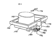
映像系移動枠166には、X線をその強度に応じた強度の光に変換する受像装置168が取付け枠170を介して取り付けられている。受像装置168によって作られた光は光路172を介してカメラ174に導かれる。カメラ174で検出されたX線像はモニター400に表示されるとともに、操作により記録され、撮影される。図8は受像装置168の拡大図である。図8に矢印176で示すX方向の撮像装置168の移動制御は、移動枠166に固定されたモータ178と減速機180、取付け枠170に固定されたラック184とこれにかみあい減速機180により回転させられるピニオン182によって行われる。移動枠166全体がモータ156とチェーン158によりX方向に移動し、移動枠166内でモータ178の回転のよりピニオン182とラック184によりY方向に移動する。Y方向の位置はピニオンの回転をベルト188を介して受ける絶対値センサ186により検出される。この機構で撮像装置を移動するのでX方向Y方向の移動装置が小型にでき、また薄くできベッドの高さに対する制約を少なくしている。従って必要なだけテーブル12を下方に下げても検査室の床に当たることが無い。このため治療しながら撮影する場合テーブル上の患者の高さを治療しやすい高さに維持できる。またこれらの装置がベッド下方に位置し、テーブルの周囲からはみ出すことが無いので、他の治療器具のスペースを確保でき、また医師看護婦の移動を妨げない。   An image receiving device 168 that converts X-rays into light having an intensity corresponding to the intensity of the X-ray is attached to the image-based moving frame 166 via an attachment frame 170. Light generated by the image receiving device 168 is guided to a camera 174 via an optical path 172. The X-ray image detected by the camera 174 is displayed on the monitor 400, recorded and photographed by an operation. FIG. 8 is an enlarged view of the image receiving device 168. The movement control of the imaging device 168 in the X direction indicated by an arrow 176 in FIG. 8 is performed by the motor 178 and the reduction gear 180 fixed to the moving frame 166, the rack 184 fixed to the mounting frame 170, and the rotation by the reduction gear 180. This is done by the pinion 182 being turned on. The entire moving frame 166 is moved in the X direction by the motor 156 and the chain 158, and is moved in the Y direction by the rotation of the motor 178 in the moving frame 166 by the pinion 182 and the rack 184. The position in the Y direction is detected by an absolute value sensor 186 that receives the rotation of the pinion via a belt 188. Since the imaging device is moved by this mechanism, the moving device in the X and Y directions can be reduced in size and thickness, thereby reducing restrictions on the height of the bed. Therefore, even if the table 12 is lowered downward as needed, it does not hit the floor of the examination room. For this reason, when imaging while performing treatment, the height of the patient on the table can be maintained at a height that facilitates treatment. In addition, since these devices are located below the bed and do not protrude from the periphery of the table, a space for other treatment instruments can be secured, and the movement of doctors and nurses is not hindered.

図9は医師が治療を行う状態を示す図、あるいはX線撮影において被検者の頭部を足部より低くした状態を示す図である。テーブル12が低いと医師が治療などを施す場合膝を曲げる必要が生じ、十分な治療ができない。また高過ぎても治療がスムーズに行えない。従って治療する場合、テーブル12の上面である天板14の高さL2が800mm以上で、その高さ調整範囲L1が400mm程度有ることが望ましい。床からの高さにはすると800mmから1200mmの範囲で上下することが望ましい。天板14を下げた場合、テーブル12の支持機構60の上端が天板14より上になるとまた治療の邪魔となる。従って支持機構60内のシリンダー80は3段シリンダーとなっており、縮んだ状態での高さを低く押さえている。また撮像装置160の高さを低く押さえているのでテーブル12を下げることが可能になった。上記テーブルの上下移動速度は一定ではなく可変になっている。被検者の健康状態によりゆっくり移動させるか、それとも早くX線撮影を終わらせるためにテーブル移動を早くするかを選択できるためである。また予め移動速度を複数個決めておき医師や検査技師が選択することも可能であり、この方が医師などの負担を低減し、手術などの治療に集中できる。   FIG. 9 is a diagram showing a state in which a doctor performs treatment, or a diagram showing a state in which the subject's head is lower than the foot in X-ray imaging. If the table 12 is low, the doctor needs to bend the knee when performing treatment or the like, so that sufficient treatment cannot be performed. Moreover, even if it is too high, treatment cannot be performed smoothly. Therefore, when performing treatment, it is desirable that the height L2 of the top plate 14, which is the upper surface of the table 12, be 800 mm or more and the height adjustment range L1 be about 400 mm. When the height from the floor is set, it is desirable to move up and down in a range of 800 mm to 1200 mm. When the top plate 14 is lowered, if the upper end of the support mechanism 60 of the table 12 is higher than the top plate 14, the treatment will be obstructed again. Therefore, the cylinder 80 in the support mechanism 60 is a three-stage cylinder, and keeps the height in the contracted state low. Further, since the height of the imaging device 160 is kept low, the table 12 can be lowered. The vertical movement speed of the table is not constant but variable. This is because it is possible to select whether to move the table slowly depending on the health condition of the subject or to move the table quickly to end the X-ray imaging earlier. It is also possible for a doctor or a laboratory technician to select a plurality of moving speeds in advance, thereby reducing the burden on the doctor or the like and concentrating on treatment such as surgery.

破線はテーブル12を頭を低くする方向に回転させた場合を示す。この操作は遠隔または近接操作卓で行われる。この操作の指示がでると、テーブルおよび支持機構60は自動的に所定の高さまで高くなりテーブルの頭部側が低くなる。この時テーブルの傾き速度よりテーブルの上昇速度を早くしている。また上昇速度が複数速度設定可能の場合、自動的に最低上昇速度より早い速度でテーブルが上昇する。これはできるだけ速やかに傾斜の動作を行わせるためである。すなわち胃の状態をX線撮影する場合頭部を下げる操作が行われることが有るが、バリュウムの胃の中の状態などから撮影時間をあまり長くできない。このような状況に対応する目的である。   A broken line indicates a case where the table 12 is rotated in a direction to lower the head. This operation is performed at a remote or proximity console. When this operation is instructed, the table and the support mechanism 60 are automatically raised to a predetermined height and the head of the table is lowered. At this time, the ascending speed of the table is made faster than the tilting speed of the table. When a plurality of rising speeds can be set, the table automatically rises at a speed faster than the minimum rising speed. This is because the tilting operation is performed as quickly as possible. That is, when X-ray imaging of the state of the stomach is performed, an operation of lowering the head may be performed, but the imaging time cannot be too long due to the state of the stomach of the barium. The purpose is to cope with such a situation.

テーブル12の頭部側端下面13が約45度にカットされているのは、テーブルが図のように傾斜した場合でも床面に当たらないためである。また撮像装置160の頭部側端下面173が同様にカットされているのも床面に当たるのを防止するためである。この図で分かるようにテーブル12の支持装置60はテーブルの長手方向の中心より足側に設けられている。頭部から腹部にかけての治療に関し医師の行動の妨げにならない目的、および治療器具の設置場所をできるだけ確保するためである。   The reason why the lower surface 13 on the head side end of the table 12 is cut at about 45 degrees is that the table 12 does not hit the floor even when the table is inclined as shown in the figure. The reason why the lower surface 173 of the head side end of the imaging device 160 is similarly cut is to prevent the lower surface 173 from hitting the floor surface. As can be seen from this figure, the support device 60 of the table 12 is provided on the foot side from the center in the longitudinal direction of the table. This is for the purpose of not disturbing the action of the doctor regarding the treatment from the head to the abdomen, and to secure the installation place of the treatment instrument as much as possible.

図10はカセット190と呼ばれるフィルムの挿入を説明する。このフィルムはX線に感光するフィルムであり、X線の強度に応じ色黒の濃淡ができる。このフィルムがケースに納められカセットと呼ばれる。このカセット190はテーブル12の天板14および絞り機構120の下に挿入口192から挿入され、テーブル12の下部を構成する支持枠内150に挿入される。テーブル12は比較的固い天板14と両サイドに付属品を取り付けるレール27、28が設けられて形作られそれらで構成された内側には上記カセット190が挿入されたり、絞り機構120が有ったり、撮像装置の受像装置168が釣下げられていたりする。これらの装置は他の装置とぶつかると破損するが、上記テーブル12の天板14やテーブル12のレール27、28が取り付けられている側部で保護されている。   FIG. 10 illustrates the insertion of a film called cassette 190. This film is a film that is sensitive to X-rays, and can produce shades of black depending on the intensity of the X-rays. This film is placed in a case and is called a cassette. The cassette 190 is inserted below the top plate 14 and the squeezing mechanism 120 of the table 12 from the insertion opening 192, and is inserted into a support frame 150 constituting a lower portion of the table 12. The table 12 is formed by providing a relatively hard top plate 14 and rails 27 and 28 for attaching accessories on both sides, and the cassette 190 is inserted inside the table 12 and an aperture mechanism 120 is provided. , The image receiving device 168 of the imaging device is suspended. These devices are damaged when they collide with other devices, but are protected by the top plate 14 of the table 12 and the side of the table 12 to which the rails 27 and 28 are attached.

図11は撮像装置160の代りにX線に感光するフィルムを自動的に入れ替えて数枚のX線像を撮影するフィルムチェンジャー198を使用する図である。近接操作卓500による操作により撮像装置160はテ−ブル12の足側に移動する。この移動はテーブル下部の支持枠150のレール154に沿って移動用モータ156により行われる。フィルムチェンジャー198は移動用の車が下についており、支持枠150の両サイドのレール154の内側に挿入され、連続撮影が行われる。このような構成のためフィルムチェンジャー198の挿入を簡単にしかも短時間に行える効果が有る。   FIG. 11 is a diagram in which a film changer 198 for automatically replacing a film sensitive to X-rays and photographing several X-ray images is used instead of the imaging device 160. The imaging device 160 is moved to the foot of the table 12 by the operation of the proximity console 500. This movement is performed by the movement motor 156 along the rail 154 of the support frame 150 under the table. The film changer 198 has a moving vehicle below it, and is inserted inside the rails 154 on both sides of the support frame 150 to perform continuous shooting. With such a configuration, there is an effect that the film changer 198 can be easily and quickly inserted.

図1でX線照射装置250は、天井6に固定されたX方向レール260、262とこのレールに保持されたY方向レール264、266により移動可能に釣下げられている。X方向レール260、262はベッド10の長手方向であるX方向にその上部の天井に固定されており、X方向レール260、262に沿って移動することにより、X線照射装置250はベッド10の長手方向であるX方向に移動する。またこれに移動可能に支持されたY方向レール264、266はベッド10の短い辺の方向Y方向と並行になっている。従ってY方向レール264、266に沿って移動することによりX線照射装置250をベッド10のY方向に沿って移動できる。   In FIG. 1, the X-ray irradiator 250 is movably suspended by X-direction rails 260 and 262 fixed to the ceiling 6 and Y-direction rails 264 and 266 held by these rails. The X-direction rails 260 and 262 are fixed to the ceiling above the bed 10 in the X direction, which is the longitudinal direction of the bed 10, and by moving along the X-direction rails 260 and 262, the X-ray irradiation device 250 It moves in the X direction, which is the longitudinal direction. Further, the Y-direction rails 264 and 266 movably supported thereon are parallel to the direction Y of the short side of the bed 10. Therefore, the X-ray irradiation device 250 can be moved along the Y direction of the bed 10 by moving along the Y direction rails 264 and 266.

この明細書ではレールは極めて広い意味で使用しており、凸形状の長く伸びたものだけでなく、凹形状に長く伸びこれに案内されて移動する場合この凹形状に長く伸びた案内を含めてレールと表現する。   In this specification, the rail is used in a very broad sense, and includes not only a protruding elongated member, but also a concave member that extends in a concave shape and includes a guide that extends in a concave shape. Express as a rail.

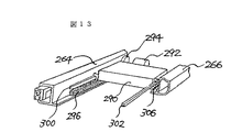
X方向とY方向の移動機構を図12と図13に示す。X方向モータ270はY方向レール264に固定され、X方向レール260、262にそれぞれ設けられたラック276に噛み合っているピニオン274にハーモニック減速機272を介してX方向モータ270の回転駆動力が伝えられる。X方向モータ270の回転方向と速度を制御することによりY方向レール264、266の移動方向と移動速度が制御できる。X方向レール260、262にはそれぞれガイドレール280、282が設けられており、Y方向レール264、266にそれぞれ設けられたガイド車286がこのガイドレール280、282に沿って動くことにより、X方向モータ270によりY方向レール264、266が移動する。両レール264、266のガイド車286はLMガイド284により覆われている。   The moving mechanism in the X direction and the Y direction is shown in FIGS. The X-direction motor 270 is fixed to the Y-direction rail 264, and the rotational driving force of the X-direction motor 270 is transmitted to the pinion 274 engaged with the rack 276 provided on each of the X-direction rails 260 and 262 via the harmonic reducer 272. Can be By controlling the rotation direction and speed of the X-direction motor 270, the movement direction and movement speed of the Y-direction rails 264 and 266 can be controlled. Guide rails 280 and 282 are provided on the X-direction rails 260 and 262, respectively, and guide wheels 286 provided on the Y-direction rails 264 and 266 move along the guide rails 280 and 282, respectively. The Y-direction rails 264 and 266 are moved by the motor 270. The guide wheels 286 of both rails 264 and 266 are covered by the LM guide 284.

図13はY方向レール264、266に対するボックス290の移動を説明する図である。Y方向レール264にラック296が設けられ、ボックス290に固定されたモータ292から減速歯車を介して回転が伝わるピニオン294は上記ラック296に噛む合いモータ292の回転方向と速度に応じボックス290が移動する。尚X方向レール264、266の内側にそれぞれガイドレール300、302が設けられ、ボックスに設けられたガイド車306がこれに沿って移動する。このボックス290にはX線照射装置が釣下げられている。   FIG. 13 is a view for explaining the movement of the box 290 with respect to the Y-direction rails 264 and 266. A rack 296 is provided on the Y-direction rail 264, and a pinion 294 to which rotation is transmitted from a motor 292 fixed to the box 290 via a reduction gear moves the box 290 according to the rotation direction and speed of the meshing motor 292 engaged with the rack 296. I do. Guide rails 300 and 302 are provided inside the X-direction rails 264 and 266, respectively, and a guide wheel 306 provided in the box moves along the guide rails. In this box 290, an X-ray irradiation device is suspended.

ここで図12と13には図示されていないがYレールやボックス292にはマイクロスイッチが設けられており、安全領域から外れることを検知し、図示しないコンピュータに信号をお繰り、警報すると共に自動的に停止する。図1の走行台車252は図12と図13のモータ及び減速機270、272、292及びボックス290などを内蔵している。以上の構成によりX線照射部のX方向Y方向の移動を簡単にし、ベッドを移動しなくてもX線照射部や撮像部をスムーズに所定の関係に移動できるので必要な撮影が可能である。またベッドをX、Y方向に移動しないため治療器具を装着でき、患者への負担も低減できる。制御モータは直流もー値を使用しており、決め細かい速度制御や方向の制御が可能である。   Although not shown in FIGS. 12 and 13, a microswitch is provided on the Y-rail or the box 292 to detect that the vehicle is out of the safety area, and to send a signal to a computer (not shown) to issue an alarm and automatically. Stop. The traveling vehicle 252 of FIG. 1 incorporates the motors and reduction gears 270, 272, 292 and the box 290 of FIGS. 12 and 13. With the above configuration, the X-ray irradiator can be easily moved in the X and Y directions, and the X-ray irradiator and the imaging unit can be smoothly moved in a predetermined relationship without moving the bed, so that necessary imaging can be performed. . In addition, since the bed does not move in the X and Y directions, the treatment instrument can be mounted, and the burden on the patient can be reduced. The control motor uses a direct current (DC) value, so that it is possible to precisely control the speed and control the direction.

次に近接操作卓500につき説明する。後述するが操作盤は、医師やX線技師をX線の被爆から守るために別の部屋に設けられており、窓越しにまたマイクなどの機器を使用して被検者と会話しながら操作するのが普通である。しかし、医学の進歩により手術をしながら、あるいは血管内に治療器具を挿入するなどの治療を施しながら、被検者の体内の状態や体内の器具の挿入の状態、位置などをX線で確認するなどが必要になってきた。このため別室の本来の操作盤の他に上記治療や手術などを行いながら、すぐその場所で操作できる近接操作卓が不可欠になってきた。   Next, the proximity console 500 will be described. As will be described later, the operation panel is provided in a separate room to protect doctors and X-ray technicians from exposure to X-rays, and is operated through windows and using a microphone or other device while talking to the subject. It is usual to do. However, while performing surgery due to advances in medicine, or performing treatment such as inserting a therapeutic instrument into a blood vessel, the subject's internal condition and the state and position of the instrument's insertion in the body are confirmed with X-rays. And so on. For this reason, in addition to the original operation panel in a separate room, a proximity console that can be operated immediately at the place while performing the above-described treatment or surgery has become indispensable.

この近接操作卓を図14、図15、図16、を使用して説明する。近接操作卓500は手前が狭く、一方向う側で有る奥側が広い形状をなし、前後関係が一目で分かる形状としている。これは医師や看護婦が治療などの他の仕事に集中できるためである。このような形状をしたケ−ス510は発泡ウレタン等のやわらかい材料で表面を覆っている。それは他の仕事に集中しながら操作卓に触れたり、ぶつかったりしても怪我をしないためである。またケ−ス510の4角、514、515、516、517は角を落しており、5mm以上望ましくは20mm以上の丸みを付けることが上記目的・効果から必要となる。この実施形態では角514、517が30mm、角515、516が50mmの丸みである。手前にグリップ512が有り、操作卓を引き寄せるのに使用できる。またグリップ512の奥は幅30mm〜50mmで横長の穴520を設けている。グリップ512を握らなくても上記横長穴520に手を入れるのみで操作卓を前後左右、上下に移動できる。長手穴奥の角522はやはり丸みを設けており、15mmである。しかし凸角でなく凹角なので小さくてよく血液や薬品などの汚れがふき取りやすくなる効果が有る。ケ−ス510の内側に多数の操作スイッチやジョイスティック、表示装置が有る。   This proximity console will be described with reference to FIG. 14, FIG. 15, and FIG. The proximity console 500 has a shape in which the near side is narrow and the back side which is one side is wide, so that the front-back relationship can be seen at a glance. This is because doctors and nurses can focus on other tasks such as treatment. The case 510 having such a shape is covered with a soft material such as urethane foam. This is to avoid injury when touching or hitting the console while concentrating on other tasks. In addition, the four corners, 514, 515, 516, and 517 of the case 510 are rounded, and it is necessary to make the corners 5 mm or more, preferably 20 mm or more from the above-mentioned objects and effects. In this embodiment, the corners 514 and 517 are rounded at 30 mm, and the corners 515 and 516 are rounded at 50 mm. There is a grip 512 in front, which can be used to pull the console. The back of the grip 512 is provided with a horizontally long hole 520 having a width of 30 mm to 50 mm. The operator can move the console up and down, left and right, and up and down only by putting his hand in the horizontally long hole 520 without grasping the grip 512. The corner 522 at the back of the longitudinal hole is also rounded and is 15 mm. However, since it is not a convex angle but a concave angle, it is small and has an effect of easily removing dirt such as blood and chemicals. Inside the case 510, there are a large number of operation switches, joysticks, and display devices.

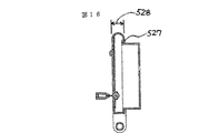
図15は側面図、図16は断面図である。ケ−ス510の中央にはスイッチやジョイスティックが有り、一方裏面には裏蓋524が有り、この裏蓋524は天井から釣り下がったアームや、後述する車輪を有する台により保持される。ケ−ス510に比べ裏蓋524は小さく、ケ−スの周囲は曲面となっており握り易い。この実施形態では周囲526は円に近い曲面である。手のひっかかりを作るため、裏側に凹み溝527が有る。厚み528は、近接操作卓の移動のしやすさから20mmから60mmが望ましい。ジョイスティックは裏蓋524の投影面内に配置され、ジョイスティックの検出部の寸法関係の問題は裏蓋524の厚みで解決している。   FIG. 15 is a side view, and FIG. 16 is a sectional view. A switch and a joystick are provided at the center of the case 510, while a back cover 524 is provided on the back surface. The back cover 524 is held by an arm hanging from the ceiling or a base having wheels described later. The back cover 524 is smaller than the case 510, and the periphery of the case is curved and easy to grasp. In this embodiment, the periphery 526 is a curved surface close to a circle. There is a recessed groove 527 on the back side to create a hook for the hand. The thickness 528 is desirably 20 mm to 60 mm from the viewpoint of ease of movement of the proximity console. The joystick is arranged in the projection plane of the back cover 524, and the problem of the dimensional relationship of the joystick detection unit is solved by the thickness of the back cover 524.

図14で奥の方540の中央部に撮影条件や状態を表示する撮影状態表示部546がある。その隣にインターロックの解除状態を示すインタ−ロック解除表示部544が有る。表示部を外側つまり奥に持ってきたことで表示が邪魔されずに見易い。左端に全体ロックスイッチ542が有る。このスイッチ542は操作卓上のスイッチやジョィスティックを誤って触れたり物がぶつかったりしてもこれによる誤動作が生じないようのするものであり、医師や看護婦の治療への集中を高める効果が有る。緊急スイッチ548が右端に設けてある。これは赤色に表示され、このスイッチを押すと全ての動作が停止する。このスイッチ548が右端奥に有り良く目に付く位置であり、正確で迅速な操作に効果が有る。   In FIG. 14, a photographing state display unit 546 that displays photographing conditions and states is provided at the center of the back side 540. Next to this is an interlock release display section 544 that indicates the release state of the interlock. By bringing the display unit to the outside, that is, to the back, the display is easy to see without disturbing. There is an overall lock switch 542 at the left end. This switch 542 is intended to prevent malfunctions caused by accidentally touching or hitting a switch or joystick on the operation console, and has an effect of increasing the concentration of doctors and nurses on treatment. Yes. An emergency switch 548 is provided at the right end. This is displayed in red, and pressing this switch stops all operations. This switch 548 is located at the far right of the right end and is easily visible, which is effective for accurate and quick operation.

スイッチ群552はX線照射部の位置制御の機能を持ち、X方向レールやY方向レールに沿った移動、アームの制御、高さ設定ができる。スイッチ554はX線照射部の高さ設定スイッチで2つの既設定高さが準備されており、このスイッチの1つで選択することにより既設定高さを選択して自動的に位置決めでき、迅速で正確な操作が可能になる。スイッチ群556はX線撮影条件の設定機能を持ち、スイッチ群558でX線撮影部の大きさ、例えば16インチ、12インチ等を選択的に決める。スイッチ群560は撮影された像の配置を決める選択スイッチで例えば4つの像を1枚に配置するか2つの像を1枚に配置するかなどを決める。尚モニター表示の1つはこの条件に従い他の一つは拡大を表示する。スイッチ群562は画面の配置反転や上下反転スイッチであり、X線像の表示が操作できまた撮影画面もこれに従う。スイッチ群564は自動撮影の制御機能、設定機能を持つ。スイッチ群590は絞り制御機能をもちスイッチ591はX方向やY方向のマスクの並行移動制御、スイッチ群592はここのマスクをそれぞれ単独で移動させる機能を持ち、移動量と方向はジョイスティック594で行われる。   The switch group 552 has a function of controlling the position of the X-ray irradiating unit, and can move along the X-direction rail or the Y-direction rail, control the arm, and set the height. The switch 554 is a height setting switch of the X-ray irradiating unit, and two preset heights are prepared. By selecting one of these switches, the preset height can be selected and the position can be automatically determined, and the position can be quickly determined. And accurate operation becomes possible. The switch group 556 has a function of setting X-ray imaging conditions, and the switch group 558 selectively determines the size of the X-ray imaging unit, for example, 16 inches or 12 inches. A switch group 560 is a selection switch for determining the arrangement of captured images, and determines, for example, whether to arrange four images or one image to two images. It should be noted that one of the monitor displays displays the enlarged one according to this condition. The switch group 562 is a switch for reversing the arrangement of the screen and for reversing the screen, and can operate the display of the X-ray image, and the photographing screen follows the operation. The switch group 564 has a control function and a setting function for automatic photographing. A switch group 590 has an aperture control function, a switch 591 has a function of moving the mask in the X direction and the Y direction in parallel, and a switch group 592 has a function of moving the mask alone, and the movement amount and direction are controlled by the joystick 594. Is

スイッチ群610はフィルタと呼ばれるX線照射範囲を決める機能を持ち、スイッチ612で照射範囲を広くするか狭くするか選択的に決められる。このフィルタはX線照射部に設けられており、例えば4個の絞り板で行われ、これらそれぞれの絞り板の移動はジョイスティック614でそれぞれについて位置決めできる。スイッチ群570はX線照射部とベッドの関係を制御する機能を持ち、スイッチ576はテーブル10の上げ下げを制御する機能を持ち、スイッチ574はテーブル12の傾きをそのまま維持しX線の照射角のみを傾ける機能を持ち、スイッチ572は被検者の乗り降りのためにテーブルを立てる機能を持つ。またスイッチ578はテーブルの頭側を下げる機能を持つ。テーブルの回転つまり傾斜はジョイスティクで自在に制御できる。テーブル傾斜は誤動作を防止するためスイッチ578とジョイスティック580の両方の操作で動作するようになっており、物があ取ったことによる誤動作を防止でき安全性が向上している。スイッチ群566は圧迫管の操作機能を持ち、ジョイスティック568は圧迫筒を自在に操作できる機能を持つ。スイッチ群620はX線撮影機能を持ち、スイッチ622は撮影前の像確認のためのX線量を弱める機能を持つ。スイッチ624、626は撮影タイミングの調整や所定時間後のX線照射の停止機能を持つ。ジョイスティック628は受光部の位置制御機能を持ちその上部に撮影指示スイッチを備える。ジョイスティック628が同時に撮影指示スイッチを備えているので最適のタイミングを捕らえて撮影でき、精度の向上とスピードアップにつながる。   The switch group 610 has a function of determining an X-ray irradiation range called a filter, and the switch 612 can selectively determine whether to widen or narrow the irradiation range. This filter is provided in the X-ray irradiator, and is performed by, for example, four aperture plates, and the movement of each of these aperture plates can be determined by using the joystick 614 for each. A switch group 570 has a function of controlling the relationship between the X-ray irradiation unit and the bed, a switch 576 has a function of controlling the raising and lowering of the table 10, and a switch 574 maintains the inclination of the table 12 as it is and only controls the irradiation angle of the X-ray. The switch 572 has a function of setting up a table for the subject to get on and off. The switch 578 has a function of lowering the head of the table. The rotation or tilt of the table can be freely controlled with a joystick. The table tilt is operated by the operation of both the switch 578 and the joystick 580 in order to prevent malfunction, and malfunction due to removal of an object can be prevented and safety is improved. The switch group 566 has a function of operating the compression tube, and the joystick 568 has a function of freely operating the compression tube. The switch group 620 has an X-ray imaging function, and the switch 622 has a function of weakening the X-ray dose for image confirmation before imaging. The switches 624 and 626 have a function of adjusting imaging timing and stopping X-ray irradiation after a predetermined time. The joystick 628 has a function of controlling the position of the light receiving unit, and has a shooting instruction switch above the joystick. Since the joystick 628 has a photographing instruction switch at the same time, it is possible to capture an image at an optimal timing, which leads to an improvement in accuracy and an increase in speed.

以上の配置ではジョイスティックを手前にその次に操作スイッチを配置しているので、最も頻繁にしかも神経を使う最終的な位置合わせや微調整ジョイスティックを手前にしているので使用しやすい。初期設定のスイッチ群556は奥になっているが使用頻度が低くまた検査開始始めなので他に神経を使うことも少なく、近接操作卓全体をコンパクトにしかも使いやすくしている。   In the above arrangement, the joystick is positioned in front of the joystick, and the operation switch is positioned next to the joystick. Although the switch group 556 in the initial setting is located at the back, the frequency of use is low, and since the examination is started, less nerve is used, so that the entire proximity console is made compact and easy to use.

図17は他の実施形態である床置きの近接操作卓800を示す。4個の車634を有する台630に支柱640が取り付けられこれに近接操作卓500が固定されている。4個の車634はそれぞれ矢印のごとく360度回転可能に取り付けられている。また台630にはフットスイッチ632が有り、撮影の位置を決めるために微弱なX線を照射する機能を持つ。なお、近接操作卓500の上面は床2から、医師や技師が立って使用するのに適した高さである800mmから1000mmの高さを有している。   FIG. 17 shows a floor-mounted proximity console 800 according to another embodiment. A column 640 is attached to a platform 630 having four wheels 634, and the proximity console 500 is fixed to the column 640. Each of the four wheels 634 is mounted so as to be rotatable 360 degrees as indicated by arrows. The base 630 has a foot switch 632, which has a function of irradiating weak X-rays in order to determine the position of imaging. The upper surface of the proximity console 500 has a height from the floor 2 of 800 mm to 1000 mm, which is a height suitable for a doctor or a technician to stand and use.

この床置きの近接操作卓800を有する操作装置は、上述のアーム式固定の近接操作卓500で説明したと同様の効果が有るが、更に以下に述べる効果が有る。高さが所定のため床置きの近接操作卓800を横に移動させることで、所望の位置に速やかに移動することができる。   The operating device having the floor-mounted proximity console 800 has the same effects as those described for the arm-type fixed proximity console 500 described above, but also has the following effects. Since the height is predetermined, by moving the proximity console 800 on the floor sideways, it can be quickly moved to a desired position.

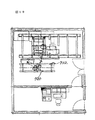
図18は部屋の上から見た図で、撮影室701と操作室700とは壁で隔てられており、窓越しに操作が行われる。ベッドは壁に並行に置かれ、ベッドの長手方向であるX方向に合わせX方向レール260、262が天井に固定されている。この実施形態ではモニター400と近接操作卓500は同じX方向レール260、262に支持されている。点線706は信号線を示す。同じX方向レール260、262を使用するので全体として簡単であり安価である。またモニター400と近接操作卓500の台車552はX線照射部の台車252の移動範囲外に設けられた範囲を移動するように設定されているので安全であり、これらの移動範囲を超えることが内容にそれぞれのオーバーラン検出のスイッチが設けられているので誤動作にも対応でき安全である。   FIG. 18 is a view from the top of the room. The photographing room 701 and the operation room 700 are separated by a wall, and the operation is performed through a window. The bed is placed in parallel with the wall, and X-direction rails 260 and 262 are fixed to the ceiling in the X direction which is the longitudinal direction of the bed. In this embodiment, the monitor 400 and the proximity console 500 are supported by the same X-direction rails 260 and 262. A dotted line 706 indicates a signal line. Since the same X-direction rails 260 and 262 are used, the whole is simple and inexpensive. Also, the monitor 400 and the cart 552 of the proximity console 500 are set so as to move in a range provided outside the moving range of the cart 252 of the X-ray irradiation unit, so that they are safe, and may not exceed these moving ranges. The contents are provided with respective overrun detection switches, so that malfunctions can be dealt with and safety is ensured.

図19は他の実施形態で同じ符号は同じ作用、効果、目的を示す。X線照射装置用の移動レールと並行にモニターあるいは近接操作卓線用のレール720、722を設けている。   FIG. 19 shows the same operation, effect and purpose in the other embodiments by the same reference numerals. Rails 720 and 722 for a monitor or a proximity operation table are provided in parallel with the moving rail for the X-ray irradiation device.

前述した本発明の各実施形態によれば、ベッドの縦支持機構がベッドの一方の側でしかもベッドの長手方向の中心より端部側に、例えば、被治療者の足元側に配置されているので、被治療者の上半身のベッド周囲における医師の移動、治療作業の妨げにならず、また、他の治療器具を設置するスペースを確保することができる。   According to each of the embodiments of the present invention described above, the vertical support mechanism of the bed is disposed on one side of the bed and on the end side from the center in the longitudinal direction of the bed, for example, on the foot side of the patient. Therefore, the movement of the doctor around the bed of the upper body of the patient and the treatment work are not hindered, and a space for installing another treatment instrument can be secured.

本発明の一実施形態による二方向透視撮影機能を有するX線撮影装置の構成を示す図である。1 is a diagram illustrating a configuration of an X-ray imaging apparatus having a two-way fluoroscopic imaging function according to an embodiment of the present invention. ベッドの構成を説明する拡大図である。It is an enlarged view explaining the structure of a bed. ベッドの姿勢を制御する制御機構の構成を示す図である。It is a figure showing composition of a control mechanism which controls a posture of a bed. ベッドのグリップの構成を示す図である。It is a figure showing composition of a grip of a bed. X線のマスク機能を果たす絞り機構の制御を制御する図である。FIG. 4 is a diagram for controlling the control of a diaphragm mechanism that performs an X-ray mask function. X線のマスク機能を果たす絞り機構の制御を制御する図である。FIG. 4 is a diagram for controlling the control of a diaphragm mechanism that performs an X-ray mask function. X線検知手段である撮像機構の構成を示す図である。FIG. 2 is a diagram illustrating a configuration of an imaging mechanism that is an X-ray detection unit. 撮像機構の受像装置の構成を示す拡大図である。FIG. 2 is an enlarged view illustrating a configuration of an image receiving device of the imaging mechanism. 医師が患者の治療を行う状態を説明する図である。It is a figure explaining the state where a doctor treats a patient. フィルムが装填されたカセットの挿入を説明する図である。FIG. 4 is a diagram illustrating insertion of a cassette loaded with a film. カセットに代るフィルムチェンジャーの挿入を説明する図である。It is a figure explaining insertion of a film changer instead of a cassette. X線照射装置の移動機構の構成を説明する図である。FIG. 3 is a diagram illustrating a configuration of a moving mechanism of the X-ray irradiation device. X線照射装置の移動機構の構成を説明する図である。FIG. 3 is a diagram illustrating a configuration of a moving mechanism of the X-ray irradiation device. 近接操作卓の構成を示す正面図である。It is a front view which shows the structure of a proximity console. 近接操作卓の構成を示す側面図である。It is a side view which shows the structure of a proximity console. 近接操作卓の構成を示す断面図である。It is sectional drawing which shows the structure of a proximity console. 近接操作卓の他の構成例である床置きの操作卓を示す正面図である。It is a front view which shows the floor-mounted operation console which is another example of a structure of a proximity operation console. 本発明の一実施形態によるX線撮影装置の配置状況を説明する部屋の上から見た配置図である。FIG. 2 is a plan view illustrating a layout state of the X-ray imaging apparatus according to the embodiment of the present invention, as viewed from above a room. 本発明の一実施形態によるX線撮影装置の配置状況の他の例を説明する部屋の上から見た配置図である。It is the arrangement | positioning figure seen from the room explaining the other example of arrangement | positioning state of the X-ray imaging apparatus by one Embodiment of this invention.

符号の説明Explanation of reference numerals

4、5 検査室の壁
6 天井
10 ベッド
12 テーブル
14 天板
26 フットレスト
30 グリップ
34 肩当て
36 圧迫管
60 支持機構
70 制御ボックス
72 油圧ユニット
80 油圧シリンダー
160 X線検知手段
168 受像装置
190 カセット
198 フィルムチェンジャー
250 X線照射装置
400 モニター装置
500 近接操作卓
4, 5 Exam room wall 6 Ceiling 10 Bed 12 Table 14 Top plate 26 Footrest 30 Grip 34 Shoulder pad 36 Compression tube 60 Supporting mechanism 70 Control box 72 Hydraulic unit 80 Hydraulic cylinder 160 X-ray detecting means 168 Image receiving device 190 Cassette 198 Film Changer 250 X-ray irradiation device 400 Monitor device 500 Proximity console

Claims (12)

被検者を乗せるベッドのテーブルと、
ベッドの長手方向に対し直角方向の軸でテーブルを傾斜させるとともにテーブルを上下させる機能を有するテーブル支持装置と、
ベッドの被検者側上部にテーブル上面から距離を置いて位置するX線照射装置と、
テーブルの下部に位置するX線像撮像装置とからなり、
前記支持装置は、ベッドの側部からテーブルを支持する横支持体と前記横支持体を上下させる縦支持機構を有し、
前記支持装置は、ベッドの長手方向の一端側で前記テーブルを支持し、
前記X線像撮像装置は、ベッドの長手方向の他端側の底面に取り付けられていることを特徴とするX線撮影装置。
A bed table on which the subject is placed,
A table support device having a function of tilting the table about an axis perpendicular to the longitudinal direction of the bed and moving the table up and down,
An X-ray irradiator located at a distance from the table top on the subject side of the bed,
An X-ray image pickup device located at the lower part of the table,
The support device has a horizontal support for supporting the table from the side of the bed and a vertical support mechanism for raising and lowering the horizontal support,
The support device supports the table at one longitudinal end of the bed,
The X-ray imaging apparatus, wherein the X-ray imaging apparatus is attached to a bottom surface at the other end in the longitudinal direction of the bed.
請求項1において、前記テーブルの上面が600mmから1200mmの範囲内で水平に置かれた状態では前記縦支持機構の上端は前記テーブル上面以下に維持されることを特徴とするX線撮影装置。   2. The X-ray imaging apparatus according to claim 1, wherein the upper end of the vertical support mechanism is kept below the upper surface of the table when the upper surface of the table is placed horizontally within a range of 600 mm to 1200 mm. 請求項1において、前記テーブルの上面が800mm以下に下がるようにしたことを特徴とするX線撮影装置。   2. An X-ray imaging apparatus according to claim 1, wherein the upper surface of said table is lowered to 800 mm or less. 請求項1において、アクセサリー取り付け手段をテーブルの長手方向の側面に取り付けたことを特徴とするX線撮影装置。   2. An X-ray imaging apparatus according to claim 1, wherein the accessory mounting means is mounted on a side surface in a longitudinal direction of the table. 請求項1において、前記テーブルの頭部側端部の下面をカットしたことを特徴とするX線撮影装置。   2. The X-ray imaging apparatus according to claim 1, wherein a lower surface of a head side end of the table is cut. 請求項1において、前記テーブルの頭部側端部にX線像撮影フィルムを挿入する挿入口を設けたことを特徴とするX線撮影装置。   2. The X-ray imaging apparatus according to claim 1, wherein an insertion opening for inserting an X-ray imaging film is provided at an end of the table on the head side. 請求項1において、前記テーブルは上面に天板を有し、その両サイド側面にアクセサリーを取り付けるレールを設け、前記天板と前記両サイド側面により作られる空間の内側にX線像撮影フィルムが頭側より挿入されるようにしたことを特徴とするX線撮影装置。   2. The table according to claim 1, wherein the table has a top plate on its top surface, rails for attaching accessories are provided on both side surfaces thereof, and an X-ray film is mounted inside a space formed by the top plate and the both side surfaces. An X-ray imaging apparatus characterized by being inserted from the side. 請求項1において、前記X線像撮像装置のテーブルの頭側の方向の端部下面をカットしたことを特徴とするX線撮影装置。   2. The X-ray imaging apparatus according to claim 1, wherein a lower surface of an end of the table of the X-ray imaging apparatus in a head side direction is cut. 請求項1において、前記テーブル側面にグリップ固定手段を設け、グリップの足部がベッド側面に沿って伸び前記グリップ固定手段に回転可能に支持されていることを特徴とするX線撮影装置。   2. The X-ray imaging apparatus according to claim 1, wherein a grip fixing means is provided on the side surface of the table, and a foot portion of the grip extends along the side surface of the bed and is rotatably supported by the grip fixing means. 請求項9において、前記グリップ部はその少なくとも頭側が傾斜していることを特徴とするX線撮影装置。   The X-ray imaging apparatus according to claim 9, wherein at least a head side of the grip portion is inclined. 請求項1において、前記X線像撮像装置は、X線受像部と、X線受像部を移動させる案内部とを備え、前記X線受像部は、前記案内部を介してベッドの長手方向に移動可能に取り付けられていることを特徴とするX線撮影装置。   2. The X-ray image capturing apparatus according to claim 1, further comprising an X-ray image receiving unit, and a guide unit configured to move the X-ray image receiving unit, wherein the X-ray image receiving unit extends in a longitudinal direction of the bed via the guide unit. An X-ray imaging apparatus, which is movably mounted. 請求項11において、前記X線受像部は、前記案内部を介してベッドの長手方向と直行する方向に移動可能に取り付けられていることを特徴とするX線撮影装置。
12. The X-ray imaging apparatus according to claim 11, wherein the X-ray image receiving unit is movably mounted via the guide unit in a direction orthogonal to a longitudinal direction of the bed.
JP2004070822A 2004-03-12 2004-03-12 X-ray equipment Expired - Fee Related JP3908228B2 (en)

Priority Applications (1)

Application Number Priority Date Filing Date Title
JP2004070822A JP3908228B2 (en) 2004-03-12 2004-03-12 X-ray equipment

Applications Claiming Priority (1)

Application Number Priority Date Filing Date Title
JP2004070822A JP3908228B2 (en) 2004-03-12 2004-03-12 X-ray equipment

Related Parent Applications (1)

Application Number Title Priority Date Filing Date
JP7079148A Division JPH08275939A (en) 1995-04-04 1995-04-04 Radiography device

Publications (2)

Publication Number Publication Date
JP2004160263A true JP2004160263A (en) 2004-06-10
JP3908228B2 JP3908228B2 (en) 2007-04-25

Family

ID=32822268

Family Applications (1)

Application Number Title Priority Date Filing Date
JP2004070822A Expired - Fee Related JP3908228B2 (en) 2004-03-12 2004-03-12 X-ray equipment

Country Status (1)

Country Link
JP (1) JP3908228B2 (en)

Cited By (6)

* Cited by examiner, † Cited by third party
Publication number Priority date Publication date Assignee Title
WO2008069039A1 (en) 2006-12-05 2008-06-12 Hitachi Medical Corporation X-ray fluoroscope table and x-ray fluoroscope system
US7918603B2 (en) 2008-09-26 2011-04-05 Fujifilm Corporation Radiographic imaging table
CN102125438A (en) * 2010-01-12 2011-07-20 株式会社东芝 X-ray image diagnostic apparatus and control method of X-ray image diagnostic apparatus
US8757876B2 (en) 2009-12-18 2014-06-24 Shimadzu Corporation X-ray apparatus
WO2015012643A1 (en) * 2013-07-26 2015-01-29 Samsung Electronics Co., Ltd. X-ray imaging system
CN108523915A (en) * 2017-03-01 2018-09-14 通用电气公司 Utilize computer tomography(CT)The system and method that system carries out auxiliary anatomical structure scanning

Cited By (10)

* Cited by examiner, † Cited by third party
Publication number Priority date Publication date Assignee Title
WO2008069039A1 (en) 2006-12-05 2008-06-12 Hitachi Medical Corporation X-ray fluoroscope table and x-ray fluoroscope system
US8052325B2 (en) 2006-12-05 2011-11-08 Hitachi Medical Corporation X-ray fluoroscope table and X-ray fluoroscope system
US7918603B2 (en) 2008-09-26 2011-04-05 Fujifilm Corporation Radiographic imaging table
US8757876B2 (en) 2009-12-18 2014-06-24 Shimadzu Corporation X-ray apparatus
CN102125438A (en) * 2010-01-12 2011-07-20 株式会社东芝 X-ray image diagnostic apparatus and control method of X-ray image diagnostic apparatus
US8408788B2 (en) 2010-01-12 2013-04-02 Kabushiki Kaisha Toshiba X-ray image diagnostic apparatus and control method of X-ray image diagnostic apparatus
WO2015012643A1 (en) * 2013-07-26 2015-01-29 Samsung Electronics Co., Ltd. X-ray imaging system
US10172579B2 (en) 2013-07-26 2019-01-08 Samsung Electronics Co., Ltd. X-ray imaging system
CN108523915A (en) * 2017-03-01 2018-09-14 通用电气公司 Utilize computer tomography(CT)The system and method that system carries out auxiliary anatomical structure scanning
CN108523915B (en) * 2017-03-01 2024-01-02 通用电气公司 System and method for assisted anatomy scanning using Computed Tomography (CT) system

Also Published As

Publication number Publication date
JP3908228B2 (en) 2007-04-25

Similar Documents

Publication Publication Date Title
US6027247A (en) X-ray photographing apparatus
US7331712B2 (en) X-ray examination apparatus that is convertible among multiple examination configurations
JP5500766B2 (en) X-ray imaging device
EP3342349B1 (en) Robotic operating table and hybrid operating system
JP4179564B2 (en) X-ray fluoroscopy table and X-ray fluoroscopy system
JPH06133965A (en) Bed for fluoroscopy
WO2001010300A1 (en) Mobile radiography device
JPH08275936A (en) Radiography device
JPH11285492A (en) Photofluoroscope and photofluorography
JP6056974B2 (en) X-ray equipment
JPH08275939A (en) Radiography device
JP5085219B2 (en) CT system for surgery
JPH09140689A (en) X-ray photographing system and control method therefor
JP3908228B2 (en) X-ray equipment
JPH08275941A (en) Radiography device
KR101105624B1 (en) Diagnosis apparatus with automatic position adjustable x-ray detector
EP3329849A1 (en) Radiation-emitting device
JP2009112390A (en) X-ray fluoroscope
JP2007252715A (en) X-ray image diagnostic apparatus
JP4016713B2 (en) X-ray diagnostic equipment
JP2004313739A (en) X-ray imaging apparatus
CN114587614A (en) Operation panel system of ERCP surgical robot
JP5444422B2 (en) Intraoperative medical imaging system
CN111821060A (en) Integrated equipment based on pet diagnosis and operation
JP2002253547A (en) X-ray protective device and x-ray diagnosing bed installation using the same

Legal Events

Date Code Title Description
A621 Written request for application examination

Free format text: JAPANESE INTERMEDIATE CODE: A621

Effective date: 20040312

A131 Notification of reasons for refusal

Free format text: JAPANESE INTERMEDIATE CODE: A131

Effective date: 20060711

A521 Request for written amendment filed

Free format text: JAPANESE INTERMEDIATE CODE: A523

Effective date: 20060908

A131 Notification of reasons for refusal

Free format text: JAPANESE INTERMEDIATE CODE: A131

Effective date: 20061017

A521 Request for written amendment filed

Free format text: JAPANESE INTERMEDIATE CODE: A523

Effective date: 20061214

TRDD Decision of grant or rejection written
A01 Written decision to grant a patent or to grant a registration (utility model)

Free format text: JAPANESE INTERMEDIATE CODE: A01

Effective date: 20070109

A61 First payment of annual fees (during grant procedure)

Free format text: JAPANESE INTERMEDIATE CODE: A61

Effective date: 20070117

R150 Certificate of patent or registration of utility model

Free format text: JAPANESE INTERMEDIATE CODE: R150

LAPS Cancellation because of no payment of annual fees