JP2004158562A - Semiconductor light element, semiconductor laser element, semiconductor optical modulator, and semiconductor optical integrated device - Google Patents
Semiconductor light element, semiconductor laser element, semiconductor optical modulator, and semiconductor optical integrated device Download PDFInfo
- Publication number
- JP2004158562A JP2004158562A JP2002321568A JP2002321568A JP2004158562A JP 2004158562 A JP2004158562 A JP 2004158562A JP 2002321568 A JP2002321568 A JP 2002321568A JP 2002321568 A JP2002321568 A JP 2002321568A JP 2004158562 A JP2004158562 A JP 2004158562A
- Authority
- JP
- Japan
- Prior art keywords
- layer
- semiconductor
- semiconductor layer
- optical waveguide
- type semiconductor
- Prior art date
- Legal status (The legal status is an assumption and is not a legal conclusion. Google has not performed a legal analysis and makes no representation as to the accuracy of the status listed.)
- Pending
Links
Images


Classifications
-
- H—ELECTRICITY
- H01—ELECTRIC ELEMENTS
- H01S—DEVICES USING THE PROCESS OF LIGHT AMPLIFICATION BY STIMULATED EMISSION OF RADIATION [LASER] TO AMPLIFY OR GENERATE LIGHT; DEVICES USING STIMULATED EMISSION OF ELECTROMAGNETIC RADIATION IN WAVE RANGES OTHER THAN OPTICAL
- H01S5/00—Semiconductor lasers
- H01S5/20—Structure or shape of the semiconductor body to guide the optical wave ; Confining structures perpendicular to the optical axis, e.g. index or gain guiding, stripe geometry, broad area lasers, gain tailoring, transverse or lateral reflectors, special cladding structures, MQW barrier reflection layers
- H01S5/22—Structure or shape of the semiconductor body to guide the optical wave ; Confining structures perpendicular to the optical axis, e.g. index or gain guiding, stripe geometry, broad area lasers, gain tailoring, transverse or lateral reflectors, special cladding structures, MQW barrier reflection layers having a ridge or stripe structure
- H01S5/227—Buried mesa structure ; Striped active layer
-
- H—ELECTRICITY
- H01—ELECTRIC ELEMENTS
- H01S—DEVICES USING THE PROCESS OF LIGHT AMPLIFICATION BY STIMULATED EMISSION OF RADIATION [LASER] TO AMPLIFY OR GENERATE LIGHT; DEVICES USING STIMULATED EMISSION OF ELECTROMAGNETIC RADIATION IN WAVE RANGES OTHER THAN OPTICAL
- H01S5/00—Semiconductor lasers
- H01S5/02—Structural details or components not essential to laser action
- H01S5/026—Monolithically integrated components, e.g. waveguides, monitoring photo-detectors, drivers
- H01S5/0265—Intensity modulators
-
- H—ELECTRICITY
- H01—ELECTRIC ELEMENTS
- H01S—DEVICES USING THE PROCESS OF LIGHT AMPLIFICATION BY STIMULATED EMISSION OF RADIATION [LASER] TO AMPLIFY OR GENERATE LIGHT; DEVICES USING STIMULATED EMISSION OF ELECTROMAGNETIC RADIATION IN WAVE RANGES OTHER THAN OPTICAL
- H01S2301/00—Functional characteristics
- H01S2301/17—Semiconductor lasers comprising special layers
- H01S2301/176—Specific passivation layers on surfaces other than the emission facet
-
- H—ELECTRICITY
- H01—ELECTRIC ELEMENTS
- H01S—DEVICES USING THE PROCESS OF LIGHT AMPLIFICATION BY STIMULATED EMISSION OF RADIATION [LASER] TO AMPLIFY OR GENERATE LIGHT; DEVICES USING STIMULATED EMISSION OF ELECTROMAGNETIC RADIATION IN WAVE RANGES OTHER THAN OPTICAL
- H01S5/00—Semiconductor lasers
- H01S5/04—Processes or apparatus for excitation, e.g. pumping, e.g. by electron beams
- H01S5/042—Electrical excitation ; Circuits therefor
- H01S5/0425—Electrodes, e.g. characterised by the structure
- H01S5/04256—Electrodes, e.g. characterised by the structure characterised by the configuration
-
- H—ELECTRICITY
- H01—ELECTRIC ELEMENTS
- H01S—DEVICES USING THE PROCESS OF LIGHT AMPLIFICATION BY STIMULATED EMISSION OF RADIATION [LASER] TO AMPLIFY OR GENERATE LIGHT; DEVICES USING STIMULATED EMISSION OF ELECTROMAGNETIC RADIATION IN WAVE RANGES OTHER THAN OPTICAL
- H01S5/00—Semiconductor lasers
- H01S5/20—Structure or shape of the semiconductor body to guide the optical wave ; Confining structures perpendicular to the optical axis, e.g. index or gain guiding, stripe geometry, broad area lasers, gain tailoring, transverse or lateral reflectors, special cladding structures, MQW barrier reflection layers
- H01S5/22—Structure or shape of the semiconductor body to guide the optical wave ; Confining structures perpendicular to the optical axis, e.g. index or gain guiding, stripe geometry, broad area lasers, gain tailoring, transverse or lateral reflectors, special cladding structures, MQW barrier reflection layers having a ridge or stripe structure
- H01S5/2205—Structure or shape of the semiconductor body to guide the optical wave ; Confining structures perpendicular to the optical axis, e.g. index or gain guiding, stripe geometry, broad area lasers, gain tailoring, transverse or lateral reflectors, special cladding structures, MQW barrier reflection layers having a ridge or stripe structure comprising special burying or current confinement layers
- H01S5/2222—Structure or shape of the semiconductor body to guide the optical wave ; Confining structures perpendicular to the optical axis, e.g. index or gain guiding, stripe geometry, broad area lasers, gain tailoring, transverse or lateral reflectors, special cladding structures, MQW barrier reflection layers having a ridge or stripe structure comprising special burying or current confinement layers having special electric properties
- H01S5/2224—Structure or shape of the semiconductor body to guide the optical wave ; Confining structures perpendicular to the optical axis, e.g. index or gain guiding, stripe geometry, broad area lasers, gain tailoring, transverse or lateral reflectors, special cladding structures, MQW barrier reflection layers having a ridge or stripe structure comprising special burying or current confinement layers having special electric properties semi-insulating semiconductors
-
- H—ELECTRICITY
- H01—ELECTRIC ELEMENTS
- H01S—DEVICES USING THE PROCESS OF LIGHT AMPLIFICATION BY STIMULATED EMISSION OF RADIATION [LASER] TO AMPLIFY OR GENERATE LIGHT; DEVICES USING STIMULATED EMISSION OF ELECTROMAGNETIC RADIATION IN WAVE RANGES OTHER THAN OPTICAL
- H01S5/00—Semiconductor lasers
- H01S5/20—Structure or shape of the semiconductor body to guide the optical wave ; Confining structures perpendicular to the optical axis, e.g. index or gain guiding, stripe geometry, broad area lasers, gain tailoring, transverse or lateral reflectors, special cladding structures, MQW barrier reflection layers
- H01S5/22—Structure or shape of the semiconductor body to guide the optical wave ; Confining structures perpendicular to the optical axis, e.g. index or gain guiding, stripe geometry, broad area lasers, gain tailoring, transverse or lateral reflectors, special cladding structures, MQW barrier reflection layers having a ridge or stripe structure
- H01S5/227—Buried mesa structure ; Striped active layer
- H01S5/2275—Buried mesa structure ; Striped active layer mesa created by etching
- H01S5/2277—Buried mesa structure ; Striped active layer mesa created by etching double channel planar buried heterostructure [DCPBH] laser
-
- H—ELECTRICITY
- H01—ELECTRIC ELEMENTS
- H01S—DEVICES USING THE PROCESS OF LIGHT AMPLIFICATION BY STIMULATED EMISSION OF RADIATION [LASER] TO AMPLIFY OR GENERATE LIGHT; DEVICES USING STIMULATED EMISSION OF ELECTROMAGNETIC RADIATION IN WAVE RANGES OTHER THAN OPTICAL
- H01S5/00—Semiconductor lasers
- H01S5/30—Structure or shape of the active region; Materials used for the active region
- H01S5/32—Structure or shape of the active region; Materials used for the active region comprising PN junctions, e.g. hetero- or double- heterostructures
- H01S5/323—Structure or shape of the active region; Materials used for the active region comprising PN junctions, e.g. hetero- or double- heterostructures in AIIIBV compounds, e.g. AlGaAs-laser, InP-based laser
- H01S5/3235—Structure or shape of the active region; Materials used for the active region comprising PN junctions, e.g. hetero- or double- heterostructures in AIIIBV compounds, e.g. AlGaAs-laser, InP-based laser emitting light at a wavelength longer than 1000 nm, e.g. InP-based 1300 nm and 1500 nm lasers
- H01S5/32391—Structure or shape of the active region; Materials used for the active region comprising PN junctions, e.g. hetero- or double- heterostructures in AIIIBV compounds, e.g. AlGaAs-laser, InP-based laser emitting light at a wavelength longer than 1000 nm, e.g. InP-based 1300 nm and 1500 nm lasers based on In(Ga)(As)P
Abstract
Description
【0001】
【発明の属する技術分野】
本発明は、半導体光素子、半導体レーザ素子、半導体光変調素子、及び半導体光集積素子に関する。
【0002】
【従来の技術】
近年、長距離大容量通信用として、高速変調された光信号を発生できる半導体レーザ素子といった半導体光素子が必要とされている。図11は、従来の半導体レーザ素子の一例を示す断面図である。この半導体レーザ素子900では、n型半導体基板902上にn型バッファ層903が設けられる。n型バッファ層903上に第1のp型クラッド層910が設けられる。そして、n型バッファ層903と第1のp型クラッド層910との間に、活性層909が設けられる。こうして、n型バッファ層903、第1のp型クラッド層910、及び活性層909によって半導体導波路部912が構成される。また、半導体レーザ素子900は、活性層909に流す電流を狭窄するための高抵抗層904を備えている。高抵抗層904上には、高抵抗層904を通過しようとする正孔を阻止するためのn型ホールブロック層905が設けられる。第1のp型クラッド層910上及びn型ホールブロック層905上には、第2のp型クラッド層906及びコンタクト層907が設けられる。コンタクト層907上には、アノード電極911が設けられる。また、n型半導体基板902の裏面には、カソード電極901が設けられる。
【0003】
この半導体レーザ素子900は、第2のp型クラッド層906とn型ホールブロック層905とがpn接合を構成する。このpn接合には寄生容量が生じ、半導体レーザ素子900を高速に駆動する際に信号波形が歪むなどの影響を生じる。この寄生容量を低減するために、半導体光素子900には一対のトレンチ溝913a及び913bが形成されている。トレンチ溝913a及び913bは、高抵抗層904、n型ホールブロック層905、第2のp型クラッド層906、及びコンタクト層907を分断してバッファ層903に達している。あるいは、トレンチ溝913a及び913bはn型半導体基板902に達する。トレンチ溝913a及び913bによって接合部分が減るので、寄生容量が低減される。また、高抵抗層904と第2のp型クラッド層906との接合部分が小さくなることにより、高抵抗層904を通過する漏れ電流が低減される。トレンチ溝913a及び913bの表面には絶縁膜908が形成される。
【0004】
上記した構成と類似の構成を有する半導体レーザ素子としては、以下に示す特許文献1に開示されたものがある。また、トレンチ溝を備えないが、p型クラッド層とn型バッファ層との間に高抵抗層を備える半導体レーザ素子として、特許文献2に開示されたものがある。
【0005】
【特許文献1】
特開平8−162701号公報
【特許文献2】
特開平9−43555号公報
【0006】
【発明が解決しようとする課題】
発明者は半導体レーザ素子900といった半導体光素子をより高効率かつ高速に駆動することを検討している。そして、次の課題を見い出した。すなわち、トレンチ溝913a及び913bの表面、つまり絶縁膜908と半導体領域との間に電流経路が形成されてしまう。そして、この電流経路を通じて第2のp型クラッド層906とn型バッファ層903との間にリーク電流が流れてしまい、高抵抗層904によって駆動電流を効果的に狭窄することができない。このため、従来の半導体光素子では駆動電流を効率よく活性層909へ流すことができない。
【0007】
本発明は、駆動電流を効果的に狭窄できる構造を有する半導体光素子、半導体レーザ素子、半導体光変調素子、及び半導体光集積素子を提供することを目的とする。
【0008】
【課題を解決するための手段】
本発明による半導体光素子は、主面を有する半導体基板と、半導体基板の主面上に設けられ、活性層を含むストライプ状の光導波路と、光導波路を埋め込んでおり、半導体基板の主面に交差する方向に順に半導体基板上に配置された第1及び第2の部分を有する電流ブロック部と、電流ブロック部の第2の部分に設けられたトレンチ溝とを備える。
【0009】
上記した半導体光素子は、トレンチ溝が電流ブロック部の第2の部分に設けられることによって、光導波路とは別個の電流経路がトレンチ溝の側面に形成されないので、光導波路を通らないリーク電流を防ぎ、効果的に駆動電流を狭窄できる。
【0010】
また、半導体光素子は、電流ブロック部が、Feが添加されたInP半導体からなるブロック半導体層を有することを特徴としてもよい。これによって、高抵抗なブロック半導体層が形成されるので、電流ブロック部は駆動電流を好適に狭窄できる。
【0011】
また、半導体光素子は、ブロック半導体層の厚さが1μm以上であることを特徴としてもよい。これによって、電流ブロック部はブレイクダウンすることなく駆動電流を狭窄できる。
【0012】
また、半導体光素子は、電流ブロック部が、n型InP半導体からなるホールブロック層をさらに有することを特徴としてもよい。これによって、ブロック半導体層を通過しようとするキャリアを遮ることができるので、電流ブロック部は駆動電流をさらに効率よく狭窄できる。
【0013】
また、半導体光素子は、ブロック半導体層のFe濃度が5×1015cm−3以上であるとよい。これによって、電流ブロック部はブレイクダウンすることなく駆動電流を狭窄できる。また、半導体光素子は、ブロック半導体層のFe濃度が5×1016cm−3以下であるとよい。これによって、ブロック半導体層に添加されているFeが他の層に拡散することなく、信頼性の高い半導体光素子を提供できる。
【0014】
また、半導体光素子は、トレンチ溝の表面に設けられた絶縁膜をさらに備えることを特徴としてもよい。これによって、トレンチ溝が設けられる層を保護することができる。また、この絶縁膜は、絶縁性シリコン化合物からなるとよい。
【0015】
また、本発明による半導体レーザ素子は、主面を有する半導体基板と、半導体基板の主面上に設けられたストライプ状の光導波路と、光導波路を埋め込んで光導波路に電流を集中させるように設けられ、半導体基板の主面に交差する方向に順に半導体基板上に配置された第1及び第2の部分を有する電流ブロック部と、電流ブロック部の第2の部分に設けられたトレンチ溝とを備え、光導波路が、第1導電型半導体層と、第2導電型半導体層と、活性層とを有しており、活性層が、第1導電型半導体層及び第2導電型半導体層の間に設けられ、第1導電型半導体層及び第2導電型半導体層からキャリアが注入されることにより光が発生することを特徴とする。これによって、駆動電流を効率良く光に変換できる半導体レーザ素子を提供できる。
【0016】
また、本発明による半導体光変調素子は、主面を有する半導体基板と、半導体基板の主面上に設けられたストライプ状の光導波路と、光導波路を埋め込んでおり、半導体基板の主面に交差する方向に順に半導体基板上に配置された第1及び第2の部分を有する電流ブロック部と、電流ブロック部の第2の部分に設けられたトレンチ溝とを備え、光導波路が、第1導電型半導体層と、第2導電型半導体層と、活性層とを有しており、活性層が、第1導電型半導体層及び第2導電型半導体層の間に設けられ、第1導電型半導体層及び第2導電型半導体層の間に印加される電気信号に応じて光を吸収することを特徴とする。これによって、光を高速に変調できる半導体光変調素子を提供できる。
【0017】
また、本発明による半導体光集積素子は、主面を有する半導体基板を備え、主面は、所定の軸方向に配列されたレーザ素子領域及び光変調素子領域を有しており、当該半導体光集積素子は、レーザ素子領域上に所定の軸方向を長手方向として設けられたストライプ状の第1の光導波路と、光変調素子領域上に所定の軸方向を長手方向として設けられたストライプ状の第2の光導波路と、第1の光導波路及び第2の光導波路を埋め込んでおり、半導体基板の主面に交差する方向に順に半導体基板上に配置された第1及び第2の部分を有する電流ブロック部と、電流ブロック部の第2の部分に設けられたトレンチ溝とを備え、第1の光導波路が、第1導電型半導体層と、第2導電型半導体層と、活性層とを有しており、活性層が、第1導電型半導体層及び第2導電型半導体層の間に設けられ、第1導電型半導体層及び第2導電型半導体層からキャリアが注入されることにより光が発生し、第2の光導波路が、第1導電型半導体層と、第2導電型半導体層と、活性層とを有しており、活性層が、第1導電型半導体層及び第2導電型半導体層の間に設けられ、第1導電型半導体層及び第2導電型半導体層の間に印加される電気信号に応じて光を吸収することを特徴とする。これによって、駆動電流を効率良く光に変換でき、変換された光を高速に変調できる半導体光集積素子を提供できる。
【0018】
【発明の実施の形態】
以下、図面とともに本発明による半導体光素子の好適な実施形態について詳細に説明する。なお、図面の説明においては同一要素には同一符号を付し、重複する説明を省略する。
【0019】
(第1の実施の形態)
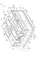
図1は、本発明による半導体光集積素子の第1実施形態を示す斜視図である。本発明による半導体光集積素子は、2つの半導体光素子、すなわち半導体レーザ素子及び半導体光変調素子を含んでいる。これらの半導体光素子は、活性層を含む光導波路の周囲を半絶縁性半導体で埋め込んだ埋込型半導体光素子である。また、これらの半導体光素子は、基板上に一体に形成される。図2は、図1に示した半導体光集積素子1の基板10を示す斜視図である。図3は、図1に示した半導体光集積素子1のI−I断面における側面断面図である。図4は、図1に示した半導体光集積素子1のII−II断面における側面断面図である。図5は、図1に示した半導体光集積素子1のIII−III断面における側面断面図である。図1〜図5を参照しながら、以下に本実施形態の半導体光集積素子1を説明する。
【0020】
半導体光集積素子1は、n型の半導体基板である基板10を備える。図2を参照すると、基板10は主面100を有する。主面100は、レーザ素子領域101及び光変調素子領域102を有する。レーザ素子領域101及び光変調素子領域102は、所定の軸方向に配列される。レーザ素子領域101は、第1の領域101a、第2の領域101b、第3の領域101c、第4の領域101d、第5の領域101e、第6の領域101f、及び第7の領域101gを有する。第1の領域101a〜第7の領域101gは、それぞれ所定の軸方向に伸びており、所定の軸と交差する方向に順に配列される。また、光変調素子領域102は、第1の領域102a、第2の領域102b、第3の領域102c、第4の領域102d、第5の領域102e、第6の領域102f、及び第7の領域102gを有する。第1の領域102a〜第7の領域102gは、それぞれ所定の軸方向に伸びており、所定の軸と交差する方向に順に配列される。
【0021】
半導体光集積素子1は、レーザ素子領域101上に設けられた半導体レーザ素子部1aと、光変調素子領域102上に設けられた半導体光変調素子1bとを有する。まず、半導体レーザ素子部1aについて説明する。
【0022】
図3を参照すると、半導体レーザ素子部1aは、カソード電極12、n型バッファ層13といった第1導電型半導体層、第1のp型クラッド層31といった第2導電型半導体層、活性層33、第2のp型クラッド層19、電流ブロック部37、コンタクト層21、絶縁膜24、及びアノード電極26を備える。電流ブロック部37は、高抵抗層15及びホールブロック層17を有する。
【0023】
これらの構成のうち、n型バッファ層13、第1のp型クラッド層31、第2のp型クラッド層19、電流ブロック部37、及びコンタクト層21は、基板10のレーザ素子領域101上に設けられる。
【0024】
n型バッファ層13は、n型InP半導体からなる。n型バッファ層13は、第1の部分13aと第2の部分13bとを有する。第1の部分13aは、主面100のレーザ素子領域101の全域上に設けられる。第2の部分13bは、第1の部分13a上であり且つレーザ素子領域101の第4の領域101d上に設けられる。
【0025】
活性層33は、ノンドープInGaAsPからなる。活性層33は、n型バッファ層13の第2の部分13b上に設けられる。また、第1のp型クラッド層31は、活性層33上に設けられる。換言すれば、活性層33はn型バッファ層13と第1のp型クラッド層31との間に設けられる。第1のp型クラッド層31は、p型InP半導体からなる。活性層33、n型バッファ層13、及び第1のp型クラッド層31はダブルへテロ構造を構成しており、活性層33にキャリアが閉じ込められるように構成されている。n型バッファ層13及び第1のp型クラッド層31から活性層33へキャリアが注入されることにより光が発生する。また、活性層33の屈折率がn型バッファ層13及びp型クラッド層31の屈折率よりも大きくなるよう各層の材料が選択される。これにより活性層33内部に光が閉じ込められ、光を導波する構成となる。
【0026】
光導波路35は、n型バッファ層13、活性層33、及び第1のp型クラッド層31を含んでおり、メサ状といった形状に構成される。光導波路33は、活性層33に光学的に結合された周期的な回折格子であるグレーティング構造331(図5に示す)を有している。また、光導波路35は、所定の軸方向を長手方向とするストライプ状に設けられる。活性層33及び第1のp型クラッド層31は、n型バッファ層13の第2の部分13bと同様に、主面100上のレーザ素子領域101の第4の領域101d上に設けられており、所定の軸方向に伸びている。
【0027】
電流ブロック部37は、メサ状に設けられた光導波路35に駆動電流を集中させるための要素である。電流ブロック部37は、高抵抗層15及びホールブロック層17を有する。高抵抗層15の抵抗値は、ホールブロック層の抵抗値よりも大きい。また、電流ブロック部37は、高抵抗層15内に第1の部分15a及び第2の部分15bを有する。
【0028】
高抵抗層15は、FeをドープされたInP半導体からなる半絶縁性半導体層である。高抵抗層15は、光導波路35を埋め込んでおり、光導波路35に流れる駆動電流を集中するよう設けられる。また、高抵抗層15の第1の部分15a及び第2の部分15bは、半導体基板10の主面100に交差する方向に順に配置される。すなわち、第1の部分15aは、n型バッファ層13上であり且つ主面100のレーザ素子領域101の第1の領域101a〜第3の領域101c上及び第5の領域101e〜第7の領域101g上に設けられる。第2の部分15bは、第1の部分15a上であり且つレーザ素子領域101の第1の領域101a上、第3の領域101c上、第5の領域101e上、及び第7の領域101g上のそれぞれに設けられる。なお、高抵抗層15は、例えば抵抗率が10×105[Ω・m]以上といった半絶縁性を有する。
【0029】
ホールブロック層17は、高抵抗層15の第2の部分15b上に設けられる。ホールブロック層17は、第2のp型クラッド層19とは逆導電型の半導体であるn型InP半導体からなる。また、ホールブロック層17は、第1のp型クラッド層31と接しないように設けられる。ホールブロック層17は、主面100からの高さが第1のp型クラッド層31の主面100からの高さと略等しくなるように設けられる。
【0030】
第2のp型クラッド層19は、p型InP半導体からなる。第2のp型クラッド層19は、第1のp型クラッド層31上及びホールブロック層17上に設けられる。コンタクト層21は、p型GaInAs半導体からなる。コンタクト層21は、第2のp型クラッド層19上に設けられる。
【0031】
半導体レーザ素子部1aは、所定の軸方向に伸びる2つのトレンチ溝29を備える。2つのトレンチ溝29のうちの一方は、主面100のレーザ素子領域101の第2の領域101b上に位置している。2つのトレンチ溝29のうちの他方は、レーザ素子領域101の第6の領域101f上に位置している。トレンチ溝29の底部は、高抵抗層15の第2の部分15bに設けられる。すなわち、トレンチ溝29は、その底面が高抵抗層15に接するように形成される。トレンチ溝29の側面は、高抵抗層15の第2の部分15b、ホールブロック層17、第2のp型クラッド層19、及びコンタクト層21によって形成される。
【0032】
また、半導体レーザ素子部1aは、絶縁膜24、アノード電極26、及びカソード電極12をさらに備える。絶縁膜24は、SiO2からなる。絶縁膜24は、コンタクト層21のうち第4の領域101d上に設けられる部分の表面に開口を有している。絶縁膜24は、トレンチ溝29の底面及び側面に設けられる。
【0033】
アノード電極26は、第1の部分26a、第2の部分26b、及び第3の部分26cを有する。第1の部分26aは、レーザ素子領域101の第4の領域101d上且つ絶縁膜24上に設けられており、絶縁膜24の開口を介してコンタクト層21に接している。第3の部分26cは、レーザ素子領域101の第1の領域101d上且つ絶縁膜24上に設けられる。第2の部分26bは、第1の部分26aと第3の部分26cとを互いに繋ぐように絶縁膜24上に設けられる。また、カソード電極12は、基板10の主面100とは反対側の面上に設けられる。
【0034】
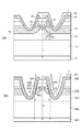
図6(a)は、半導体レーザ素子部1a内部における駆動電流の流れを示す図である。図6(a)を参照して、半導体レーザ素子部1aの動作について説明する。
【0035】
カソード電極12とアノード電極26との間に駆動装置が接続される。アノード電極26に正の駆動電圧が印加されて駆動電流I1が提供される。駆動電流I1は、コンタクト層21及び第2のp型クラッド層19を介して光導波路35に提供される。
【0036】
このとき、駆動電流I1の一部である駆動電流I2は、コンタクト層21及び第2のp型クラッド層19内部において拡がり、第2のp型クラッド層19内部のトレンチ溝29側面付近を流れる。駆動電流I2は電流ブロック部37の高抵抗層15によって狭窄され、図6(a)に示すように光導波路35へ集中する。また、電流ブロック部37内部にホールブロック層17が存在することによって、正孔が第2のp型クラッド層19から高抵抗層15を通過してn型バッファ層13へ移動することを防いでいる。こうして、駆動電流が流れる経路を電流ブロック部37によって効果的に狭窄し、駆動電流を光導波路35へ集中している。
【0037】
光導波路35は、既に述べたとおり第1のp型クラッド層31、活性層33、及びn型バッファ層13の第2の部分13bを有する。光導波路35に駆動電流が提供されることにより、第1のp型クラッド層31及びn型バッファ層13それぞれから活性層33へキャリアが流れる。キャリアは活性層33内部に閉じこめられ、活性層33内部において光が発生する。光導波路35が活性層33と光学的に結合されたグレーティング構造331を有することによって、特定波長のレーザ光が活性層33から所定の軸方向に出射される。
【0038】
本実施形態による半導体光集積素子1の半導体レーザ素子部1aが有する効果について説明する。半導体レーザ素子部1aは、第2のp型クラッド層19から光導波路35へ提供される駆動電流を電流ブロック部37によって狭窄し、光導波路35へ集中させている。また、トレンチ溝39が電流ブロック部37の第2の部分15bに設けられることによって、電流ブロック部37と絶縁層24との間に存在する電流経路がn型バッファ層13に達しない。
【0039】
ここで、図6(b)は図11に示した従来の半導体レーザ素子内部における駆動電流の流れを示す図である。アノード電極911とカソード電極901との間に駆動装置が接続され、アノード電極911から駆動電流I3が供給される。駆動電流I3は、第1のp型クラッド層910及び活性層909に提供される。このとき、駆動電流I3の一部である駆動電流I4は、第2のp型クラッド層906の両側面から電流経路Aを通ってn型バッファ層903に達する。そして、駆動電流I4は基板902を通ってカソード電極901に達する。このように、従来の半導体レーザ素子では電流経路Aが存在するために活性層909を通らない駆動電流I4、すなわちリーク電流が生じ、駆動電流を効果的に狭窄できない。
【0040】
これに対し、本実施形態による半導体レーザ素子部1aによれば、第2のp型クラッド層19の側面からn型バッファ層13へ達するような、光導波路35とは別個の電流経路が形成されないので、第2のp型クラッド層19とn型バッファ層13との間にリーク電流が流れることを防げる。よって、半導体レーザ素子部1aに印加される駆動電流を効果的に狭窄できる。駆動電流を光導波路35へ効率よく流すことができるので、半導体レーザ素子1aを高効率にできる。そして、駆動電流を効率良く光に変換できる半導体レーザ素子を提供できる。
【0041】
また、半導体レーザ素子部1aでは、第2のp型クラッド層が第2の領域101b上及び第5の領域101e上に設けられていない。換言すれば、2つのトレンチ溝29を備えることによって、第2のp型クラッド層19が分離される。ここで、これらの第2のp型クラッド層のうち、2つのトレンチ溝29に挟まれた部分に駆動電流が流れる。トレンチ溝29を備えることにより、トレンチ溝29がない場合に比べ、第2のp型クラッド層とn型バッファ層13との間に生じる寄生容量を低減できる。本実施形態による半導体レーザ素子部1aは、トレンチ溝29を設けることによるリーク電流といった悪影響を防いでいるので、トレンチ溝29を好適に設けることができる。
【0042】
また、半導体レーザ素子部1aは、電流ブロック部37がホールブロック層17を有している。これによって、高抵抗層15を通過して第2のp型クラッド層19とn型バッファ層13との間を流れようとする正孔を遮ることができるので、さらに効果的に駆動電流を狭窄できる。
【0043】
また、半導体レーザ素子部1aは、絶縁膜24を備えることが好ましい。これによって、高抵抗層15、ホールブロック層17、第2のp型クラッド層19、及びコンタクト層21を保護することができる。
【0044】
次に、半導体光変調素子部1bについて説明する。図4を参照すると、半導体光変調素子部1bは、カソード電極12、n型バッファ層14といった第1導電型半導体層、第1のp型クラッド層32といった第2導電型半導体層、光吸収層34といった活性層、第2のp型クラッド層20、電流ブロック部38、コンタクト層22、絶縁膜24、及びアノード電極28を備える。電流ブロック部38は、高抵抗層16といったブロック半導体層及びホールブロック層18を有する。
【0045】
これらの構成のうち、n型バッファ層14、第1のp型クラッド層32、光吸収層34、第2のp型クラッド層20、電流ブロック部38、及びコンタクト層22は、基板10の光変調素子領域102上に設けられる。
【0046】
n型バッファ層14は、n型InP半導体からなる。n型バッファ層14は、第1の部分14aと第2の部分14bとを有する。第1の部分14aは、主面100の光変調素子領域102の全域上に設けられる。第2の部分14bは、第1の部分14a上であり且つ光変調素子領域102の第4の領域102d上に設けられる。
【0047】
光吸収層34は、n型バッファ層14の第2の部分14b上に設けられる。また、第1のp型クラッド層32は、光吸収層34上に設けられる。換言すれば、光吸収層34はn型バッファ層14と第1のp型クラッド層32との間に設けられる。第1のp型クラッド層32は、p型InP半導体からなる。光吸収層34、n型バッファ層14、及び第1のp型クラッド層32はダブルへテロ構造を構成しており、光吸収層34にキャリアが閉じ込められるように構成されている。光吸収層34の屈折率がn型バッファ層14及びp型クラッド層32の屈折率よりも大きくなるよう各層の材料が選択される。これにより光吸収層34内部に光が閉じ込められ、光を導波する構成となる。また、光吸収層34のエネルギー帯は、半導体レーザ素子部1aの活性層33のエネルギー帯よりも大きい。
【0048】
光吸収層34は半導体レーザ素子部1aの活性層33に光学的に結合されており、活性層33において発生するレーザ光を受ける。光導波路36は、n型バッファ層14の第2の部分14b、光吸収層34、及び第1のp型クラッド層32を含んでメサ状といった形状に構成される。また、光導波路36は、所定の軸方向を長手方向とするストライプ状に設けられる。光吸収層34及び第1のp型クラッド層32は、n型バッファ層14の第2の部分14bと同様に、主面100上の光変調素子領域102の第4の領域102d上に設けられており、所定の軸方向に伸びている。
【0049】
電流ブロック部38は、光導波路36へ変調電圧を効果的に印加するための要素である。電流ブロック部38は、高抵抗層16及びホールブロック層18を有する。高抵抗部16の抵抗値は、ホールブロック層18の抵抗値よりも大きい。また、電流ブロック部38は、高抵抗層16内に第1の部分16a及び第2の部分16bを有する。
【0050】
高抵抗層16は、FeをドープされたInP半導体からなる。高抵抗層16は、光導波路36を埋め込んでいる。高抵抗層16の第1の部分16a及び第2の部分16bは、半導体基板10の主面100に交差する方向に順に配置される。すなわち、第1の部分16aは、n型バッファ層14上であり且つ主面100の光変調素子領域102の第1の領域102a〜第3の領域102c上及び第5の領域102e〜第7の領域102g上に設けられる。第2の部分16bは、第1の部分16a上であり且つ光変調素子領域102の第1の領域102a上、第3の領域102c上、第5の領域102e上、及び第7の領域102g上のそれぞれに設けられる。
【0051】
ホールブロック層18は、第2のp型クラッド層20とは逆導電型のn型半導体からなる。ホールブロック層18は、高抵抗層16の第2の部分16b上に設けられる。ホールブロック層18は、半導体レーザ素子部1aのホールブロック層17と同様の機能及び構成を有する。第2のp型クラッド層20は、半導体レーザ素子部1aの第2のp型クラッド層19と同様の構成を有する。また、コンタクト層22は、半導体レーザ素子部1aのコンタクト層21と同様の構成を有する。よって、ホールブロック層18、第2のp型クラッド層20、及びコンタクト層22についての詳細な説明を省略する。
【0052】
半導体光変調素子部1bは、所定の軸方向に伸びる2つのトレンチ溝30を備える。2つのトレンチ溝30のうち一方は、主面100の光変調素子領域102の第2の領域102b上に位置している。2つのトレンチ溝30のうち他方は、主面100の光変調素子領域102の第6の領域102f上に位置している。トレンチ溝30の底部は、高抵抗層16の第2の部分16bに設けられる。すなわち、トレンチ溝30は、その底面が高抵抗層16に接するように形成される。トレンチ溝30の側面は、高抵抗層16の第2の部分16b、ホールブロック層18、第2のp型クラッド層20、及びコンタクト層22によって形成される。2つのトレンチ溝30のそれぞれは、半導体レーザ素子部1aの2つのトレンチ溝29のそれぞれと繋がって2本の溝を構成している。
【0053】
また、半導体光変調素子部1bは、絶縁膜24、アノード電極28、及びカソード電極12をさらに備える。これらのうち、絶縁膜24及びカソード電極12は半導体レーザ素子部1aにおける絶縁膜24及びカソード電極12と共用される。
【0054】
アノード電極28は、第1の部分28a、第2の部分28b、及び第3の部分28cを有する。第1の部分28aは、光変調素子領域102の第4の領域102d上且つ絶縁膜24上に設けられており、絶縁膜24の開口を介してコンタクト層22に接している。第3の部分28cは、光変調素子領域102の第7の領域102g上且つ絶縁膜24上に設けられる。第2の部分28bは、第1の部分28aと第3の部分28cとを互いに繋ぐように絶縁膜24上に設けられる。
【0055】
以上の構成を有する半導体光変調素子部1bの動作について説明する。アノード電極28とカソード電極12との間に、アノード電極28側が負になるように変調電圧が印加される。この変調電圧は、半導体光集積素子1から外部へ出力する信号が光信号に含まれるようにレーザ光を変調する。変調電圧は、コンタクト層26、及び第2のp型クラッド層20を介して光導波路36に印加される。こうして、n型バッファ層14及び第1のp型クラッド層32の間に変調電圧が印加される。このとき、電流ブロック部38によって変調電圧は光導波路36へ効果的に印加される。
【0056】
光導波路36に変調電圧が印加されることにより、光吸収層34内部においてレーザ光が変調される。つまり、光吸収層34は、変調電圧による電界が印加されると量子閉じ込めシュタルク効果によって吸収波長がシフトする。これにより、光吸収層34は、変調電圧の絶対値がある所定の値以上のときは活性層33から提供されたレーザ光を吸収する。また、光吸収層34は、変調電圧の絶対値がある所定の値以下のときはレーザ光を吸収せずに、活性層33に接する面に対向する面からレーザ光を出力する。このようにして、光吸収層34は活性層33から受けたレーザ光を変調する。
【0057】
本実施形態による半導体光集積素子1の、半導体光変調素子部1bが有する効果について説明する。半導体光変調素子部1bは、第2のp型クラッド層20から光導波路36を通らずにn型バッファ層14へ流れる電流を電流ブロック部38によって防いでいる。これによって、光導波路36へ変調電流を効果的に印加している。また、電流ブロック部38は、第2の領域102b上及び第6の領域102f上に設けられる第1の部分16aを有する。これによって、電流ブロック部38と絶縁層24との間に存在する電流経路がn型バッファ層14へ達しないので、第2のp型クラッド層20とn型バッファ層14との間にこの電流経路を通るリーク電流が流れることを防げる。これにより、変調電圧を光導波路36へ効率よく印加することができるので、半導体光変調素子部1bを高効率にできる。
【0058】
また、半導体光変調素子部1bがトレンチ溝30を備えることによって、第2のp型クラッド層20とn型バッファ層14との間に生じる寄生容量を低減できるので、半導体光変調素子部1bはレーザ光を高速に変調できる。
【0059】
(第2の実施の形態)
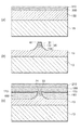
図7(a)〜図7(c)、図8(a)及び図8(b)は、第2実施形態による半導体光素子の製造方法を説明する図である。以下、本実施形態を第1実施形態による半導体レーザ素子部1aの製造方法を例に説明する。
【0060】
図7(a)を参照すると、n型InP半導体からなる基板10に、有機金属気相成長法によりn型InP半導体130(キャリア濃度1×1018cm−3)を厚さ1μmに積層する。その上に、発光波長1.3μmのノンドープInGaAsP半導体330を有機金属気相成長法により厚さ0.5μmに積層する。その上に、p型InP半導体310(キャリア濃度5×1017cm−3)を有機金属気相成長法により厚さ0.5μmに積層する。
【0061】
次に図7(b)を参照すると、通常のリソグラフィー技術を用い、第1のp型クラッド層31の表面にSiNを厚さ0.1μmに成膜して、所定の軸方向を長手方向とするマスク45を形成する。そして、2.0μmの深さまでエッチングを行い、メサ状の光導波路35を形成する。このとき、第2の部分13bを含むn型バッファ層13、活性層33、第1のp型クラッド層31が形成される。
【0062】
図7(c)を参照すると、エッチングされた部分にFeがドープされて半絶縁性を有するInP半導体150を有機金属気相成長法により積層する。FeドープInP半導体150の厚さは1.0μm以上が好ましく、本実形態では1.8μmに積層している。また、FeドープInP半導体150のFe濃度は5×1015cm−3以上5×1016cm−3以下であることが好ましい。本実施形態では、FeドープInP半導体150のFe濃度を1×1016cm−3としている。
【0063】
そして、FeドープInP半導体150上に、n型InP半導体170(キャリア濃度1×1018cm−3)を有機金属気相成長法により厚さ0.2μmに積層する。この結果、FeドープInP半導体150に光導波路35が埋め込まれる。マスク45を除去した後、第1のp型半導体層31上及びn型InP半導体170上に、p型InP半導体190(キャリア濃度1×1018cm−3)を厚さ1.5μmに成長させる。その上に、p型GaInAs半導体210(キャリア濃度5×1018cm−3)を厚さ0.5μmに成長させる。
【0064】
図8(a)を参照すると、通常のリソグラフィー技術を用い、p型GaInAs半導体210の表面にSiNを厚さ0.1μmに成膜することにより、所定の軸方向を長手方向とするマスク47をp型GaInAs半導体210の表面の中央及び両端部に形成する。そして、FeドープInP半導体150に達するとともにn型バッファ層13に達しない深さまでエッチングを行い、2つのトレンチ溝29を形成する。こうして、トレンチ溝29が設けられた高抵抗層15が形成される。また、トレンチ溝29によって分断されたホールブロック層17、第2のp型クラッド層19、及びコンタクト層21が形成される。高抵抗層15及びホールブロック層17が形成されることにより、電流ブロック部37が設けられる。
【0065】
図8(b)を参照すると、マスク47を除去した後、トレンチ溝29の表面に絶縁膜24を成膜する。絶縁膜24はSiO2といった絶縁性シリコン化合物からなり、厚さ0.3μmに成膜される。そして、絶縁膜24上にアノード電極26を形成し、基板3の主面100とは反対側の面にカソード電極12を形成する。こうして、半導体光素子が完成される。
【0066】
図9は、本実施形態による半導体レーザ素子部1aの特性と、図11に示した従来の半導体光素子の特性との比較を示すグラフである。図9は、縦軸に閾値電流、横軸に温度を示している。また、グラフAは本実施形態による半導体レーザ素子部1aを、グラフBは従来の半導体光素子を表す。
【0067】
また、下の表1は図9に示したグラフの具体的数値を示す表である。
【0068】
【表1】

図9及び表1を参照すると、本実施形態による半導体レーザ素子部1aの閾値電流は、すべての温度において従来の半導体光素子の閾値電流よりも小さいことがわかる。このように本実施形態によれば、半導体光素子の閾値電流を低減し、高効率にできる。特に、温度が高い場合にはその効果が大きい。すなわち、上記した実施形態による半導体光素子は、高温でのリーク電流の低減に特に有効である。
【0070】
半導体光素子は、本実施形態のように絶縁膜が例えばSiO2といった絶縁性シリコン化合物からなるとよい。これによって、Feを添加されたInP半導体からなる高抵抗層15と絶縁膜との間での界面準位形成を抑えることができ、保護膜として有効である。
【0071】
また、本実施形態による半導体光素子は、電流ブロック部37が、Feを添加されたInP半導体からなる高抵抗層15を有する。半導体光素子はこのような高抵抗層を有することが好ましく、これによって、電流ブロック部は駆動電流を好適に狭窄できる。
【0072】
また、半導体光素子は、本実施形態のように高抵抗層15の厚さが1μm以上であることが好ましい。これによって、電流ブロック部37はブレイクダウンすることなく安定してn型バッファ層13と第2のp型クラッド層19とを分離できるので、安定して駆動電流を狭窄できる。
【0073】
また、半導体光素子は、本実施形態のように高抵抗層15のFe濃度が5×1015cm−3以上であるとよい。これによって、高抵抗層15はブレイクダウンすることなく安定してn型バッファ層13と第2のp型クラッド層19とを分離でき、安定して駆動電流を狭窄できる。また、高抵抗層15のFe濃度は5×1016cm−3以下であるとよい。これによって、高抵抗層15に添加されているFeが他の層に拡散することなく、半導体光素子の信頼性を高めることができる。
【0074】
図10(a)及び図10(b)は、本実施形態による半導体光素子の逆方向耐圧を示すグラフである。図10(a)は、高抵抗層15のFe濃度を5×1015cm−3としている。高抵抗層15の厚さは1.5μmである。図10(b)は、高抵抗層15のFe濃度を1×1016cm−3としている。高抵抗層15の厚さは1.0μmである。図10(a)、図10(b)ともに縦軸に電流、横軸に電圧を示している。なお、温度はともに85℃である。
【0075】
図10(a)及び図10(b)によると、高抵抗層15の厚さを1.5μmにするとFe濃度が5×1015cm−3以上であれば逆方向耐圧、すなわちブレークダウン電圧を充分大きくできることがわかる。あるいはFe濃度を1×1016cm−3に上げると、厚さ1μm以上であればブレークダウン電圧を充分大きくできることがわかる。また、85℃といった高温時においても、リーク電流を効果的に低減できていることがわかる。
【0076】
本発明による半導体光素子、半導体レーザ素子、半導体光変調素子、及び半導体光集積素子は、上記した実施形態に限られるものではなく、様々な変形が可能である。例えば、上記した各実施形態ではInPを基板とするInGaAsP系の半導体光素子を説明したが、他の材料を用いる半導体光素子においても上記した各実施形態と同様の効果が得られる。
【0077】
【発明の効果】
本発明による半導体光素子、半導体レーザ素子、半導体光変調素子、及び半導体光集積素子によれば、光導波路を通らないリーク電流を低減できる構造を提供できる。
【図面の簡単な説明】
【図1】図1は、本発明による半導体光集積素子の第1実施形態を示す斜視図である。
【図2】図2は、図1に示した半導体光集積素子の基板を示す斜視図である。
【図3】図3は、図1に示した半導体光集積素子のI−I断面における側面断面図である。
【図4】図4は、図1に示した半導体光集積素子のII−II断面における側面断面図である。
【図5】図5は、図1に示した半導体光集積素子のIII−III断面における側面断面図である。
【図6】図6(a)は、半導体レーザ素子部内部における駆動電流の流れを示す図である。図6(b)は図11に示す従来の半導体レーザ素子内部における駆動電流の流れを示す図である。
【図7】図7(a)〜図7(c)は、第2実施形態による半導体光素子の製造方法を説明する図である。
【図8】図8(a)及び図8(b)は、第2実施形態による半導体光素子の製造方法を説明する図である。
【図9】図9は、第2実施形態による半導体レーザ素子の特性と、従来の半導体光素子の特性との比較を示すグラフである。
【図10】図10(a)及び図19(b)は、第2実施形態による半導体光素子の逆方向耐圧を示すグラフである。
【図11】図11は、従来の半導体レーザ素子の一例を示す断面図である。
【符号の説明】
1…半導体光集積素子、1a…半導体レーザ素子部、1b…半導体光変調素子部、10…基板、12…カソード電極、13、14…n型バッファ層、15、16…高抵抗層、17、18…ホールブロック層、19、20…第2のp型クラッド層、21、22…コンタクト層、24…絶縁膜、26、28…アノード電極、31、32…第1のp型クラッド層、33…活性層、34…光吸収層、35、36…光導波路、37、38…電流ブロック部。[0001]
TECHNICAL FIELD OF THE INVENTION
The present invention relates to a semiconductor optical device, a semiconductor laser device, a semiconductor light modulation device, and a semiconductor optical integrated device.
[0002]
[Prior art]
In recent years, for long-distance, large-capacity communication, a semiconductor optical device such as a semiconductor laser device capable of generating a high-speed modulated optical signal is required. FIG. 11 is a sectional view showing an example of a conventional semiconductor laser device. In this
[0003]
In this
[0004]
As a semiconductor laser device having a configuration similar to the above-described configuration, there is a semiconductor laser device disclosed in
[0005]
[Patent Document 1]
JP-A-8-162701
[Patent Document 2]
JP-A-9-43555
[0006]
[Problems to be solved by the invention]
The inventor is studying driving a semiconductor optical device such as the
[0007]
An object of the present invention is to provide a semiconductor optical device, a semiconductor laser device, a semiconductor optical modulation device, and a semiconductor optical integrated device having a structure capable of effectively narrowing a drive current.
[0008]
[Means for Solving the Problems]
A semiconductor optical device according to the present invention includes a semiconductor substrate having a main surface, a stripe-shaped optical waveguide provided on the main surface of the semiconductor substrate and including an active layer, and an optical waveguide embedded therein. A current block portion having first and second portions sequentially arranged on a semiconductor substrate in a direction intersecting with each other, and a trench provided in a second portion of the current block portion are provided.
[0009]
In the above-described semiconductor optical device, since the trench groove is provided in the second portion of the current block portion, a current path separate from the optical waveguide is not formed on the side surface of the trench groove. Thus, the drive current can be effectively narrowed.
[0010]
The semiconductor optical device may be characterized in that the current block has a block semiconductor layer made of an InP semiconductor to which Fe is added. As a result, a high-resistance block semiconductor layer is formed, so that the current block portion can appropriately narrow the drive current.
[0011]
Further, the semiconductor optical device may be characterized in that the thickness of the block semiconductor layer is 1 μm or more. As a result, the drive current can be narrowed in the current block section without breaking down.
[0012]
The semiconductor optical device may be characterized in that the current block further includes a hole block layer made of an n-type InP semiconductor. As a result, carriers trying to pass through the block semiconductor layer can be blocked, so that the current block portion can more efficiently restrict the drive current.
[0013]
In the semiconductor optical device, the Fe concentration of the block semiconductor layer is 5 × 10 Fifteen cm -3 It is good to be above. As a result, the drive current can be narrowed in the current block section without breaking down. In the semiconductor optical device, the Fe concentration of the block semiconductor layer is 5 × 10 16 cm -3 It is good to be the following. This makes it possible to provide a highly reliable semiconductor optical device without Fe added to the block semiconductor layer diffusing into other layers.
[0014]
The semiconductor optical device may further include an insulating film provided on a surface of the trench. Thereby, the layer provided with the trench can be protected. This insulating film is preferably made of an insulating silicon compound.
[0015]
Further, a semiconductor laser device according to the present invention is provided with a semiconductor substrate having a main surface, a stripe-shaped optical waveguide provided on the main surface of the semiconductor substrate, and an optical waveguide embedded so that current is concentrated on the optical waveguide. A current block having first and second portions disposed on the semiconductor substrate in a direction intersecting the main surface of the semiconductor substrate, and a trench provided in the second portion of the current block. Wherein the optical waveguide has a first conductivity type semiconductor layer, a second conductivity type semiconductor layer, and an active layer, and the active layer is between the first conductivity type semiconductor layer and the second conductivity type semiconductor layer. And light is generated by injecting carriers from the first conductivity type semiconductor layer and the second conductivity type semiconductor layer. Thus, a semiconductor laser device capable of efficiently converting a drive current into light can be provided.
[0016]
Further, a semiconductor light modulation device according to the present invention includes a semiconductor substrate having a main surface, a stripe-shaped optical waveguide provided on the main surface of the semiconductor substrate, and an optical waveguide embedded therein, and intersects with the main surface of the semiconductor substrate. A current block portion having first and second portions sequentially arranged on the semiconductor substrate in a direction in which the current block portion is formed, and a trench groove provided in the second portion of the current block portion. A semiconductor layer having a first conductivity type semiconductor layer, a second conductivity type semiconductor layer, and an active layer, wherein the active layer is provided between the first conductivity type semiconductor layer and the second conductivity type semiconductor layer. Light is absorbed according to an electric signal applied between the layer and the second conductivity type semiconductor layer. Thus, a semiconductor light modulation element that can modulate light at high speed can be provided.
[0017]
Further, the semiconductor optical integrated device according to the present invention includes a semiconductor substrate having a main surface, and the main surface has a laser device region and a light modulation device region arranged in a predetermined axial direction. The device has a stripe-shaped first optical waveguide provided on the laser device region with a predetermined axial direction as a longitudinal direction, and a stripe-shaped first optical waveguide provided on the light modulation device region with a predetermined axial direction as a longitudinal direction. A current having two optical waveguides and a first optical waveguide and a second optical waveguide embedded in the first optical waveguide and the second optical waveguide, the first and second optical waveguides being sequentially arranged on the semiconductor substrate in a direction intersecting the main surface of the semiconductor substrate; A first optical waveguide having a first conductive type semiconductor layer, a second conductive type semiconductor layer, and an active layer, the first optical waveguide having a block portion and a trench groove provided in a second portion of the current block portion; And the active layer is a semiconductor of the first conductivity type. Light is generated when carriers are injected from the first conductive type semiconductor layer and the second conductive type semiconductor layer, and the second optical waveguide is provided between the first conductive type semiconductor layer and the second conductive type semiconductor layer. A semiconductor layer having a first conductivity type semiconductor layer, a second conductivity type semiconductor layer, and an active layer, wherein the active layer is provided between the first conductivity type semiconductor layer and the second conductivity type semiconductor layer. Light is absorbed according to an electric signal applied between the layer and the second conductivity type semiconductor layer. As a result, it is possible to provide a semiconductor optical integrated device that can efficiently convert the drive current into light and can modulate the converted light at high speed.
[0018]
BEST MODE FOR CARRYING OUT THE INVENTION
Hereinafter, preferred embodiments of a semiconductor optical device according to the present invention will be described in detail with reference to the drawings. In the description of the drawings, the same elements will be denoted by the same reference symbols, without redundant description.
[0019]
(First Embodiment)
FIG. 1 is a perspective view showing a first embodiment of a semiconductor optical integrated device according to the present invention. The semiconductor optical integrated device according to the present invention includes two semiconductor optical devices, that is, a semiconductor laser device and a semiconductor optical modulation device. These semiconductor optical devices are embedded semiconductor optical devices in which the periphery of an optical waveguide including an active layer is embedded with a semi-insulating semiconductor. These semiconductor optical devices are formed integrally on a substrate. FIG. 2 is a perspective view showing a
[0020]
The semiconductor optical
[0021]
The semiconductor optical
[0022]
Referring to FIG. 3, the semiconductor
[0023]
Among these configurations, the n-
[0024]
The n-
[0025]
The
[0026]
The
[0027]
The
[0028]
The
[0029]
The
[0030]
The second p-
[0031]
The semiconductor
[0032]
Further, the semiconductor
[0033]
The
[0034]
FIG. 6A is a diagram showing a flow of a drive current inside the semiconductor
[0035]
A driving device is connected between the
[0036]
At this time, the drive current I which is a part of the drive current I1 2 Spreads inside the
[0037]
The
[0038]
The effects of the semiconductor
[0039]
Here, FIG. 6B is a diagram showing a flow of a driving current inside the conventional semiconductor laser device shown in FIG. A driving device is connected between the
[0040]
On the other hand, according to the semiconductor
[0041]
Further, in the semiconductor
[0042]
In the semiconductor
[0043]
Further, it is preferable that the semiconductor
[0044]
Next, the semiconductor light
[0045]
Among these components, the n-
[0046]
The n-
[0047]
The
[0048]
The
[0049]
The
[0050]
The
[0051]
The
[0052]
The semiconductor light
[0053]
The semiconductor light
[0054]
The
[0055]
The operation of the semiconductor light
[0056]
The application of the modulation voltage to the
[0057]
The effects of the semiconductor optical
[0058]
In addition, since the semiconductor light
[0059]
(Second embodiment)
FIGS. 7A to 7C, 8A and 8B are views for explaining a method of manufacturing the semiconductor optical device according to the second embodiment. Hereinafter, the present embodiment will be described with an example of the method of manufacturing the semiconductor
[0060]
Referring to FIG. 7A, an n-type InP semiconductor 130 (carrier concentration of 1 × 10 18 cm -3 ) Is laminated to a thickness of 1 μm. A non-doped
[0061]
Next, referring to FIG. 7B, using a normal lithography technique, a SiN film is formed to a thickness of 0.1 μm on the surface of the first p-
[0062]
Referring to FIG. 7C, a
[0063]
Then, on the Fe-doped
[0064]
Referring to FIG. 8A, the
[0065]
Referring to FIG. 8B, after removing the
[0066]
FIG. 9 is a graph showing a comparison between the characteristics of the
[0067]
Table 1 below is a table showing specific numerical values of the graph shown in FIG.
[0068]
[Table 1]
Referring to FIG. 9 and Table 1, it can be seen that the threshold current of the semiconductor
[0070]
In the semiconductor optical device, the insulating film is made of, for example,
[0071]
In the semiconductor optical device according to the present embodiment, the
[0072]
Further, in the semiconductor optical device, it is preferable that the thickness of the
[0073]
In the semiconductor optical device, the Fe concentration of the
[0074]
FIGS. 10A and 10B are graphs showing the reverse breakdown voltage of the semiconductor optical device according to the present embodiment. FIG. 10A shows that the Fe concentration of the
[0075]
According to FIGS. 10A and 10B, when the thickness of the
[0076]
The semiconductor optical device, the semiconductor laser device, the semiconductor optical modulation device, and the semiconductor optical integrated device according to the present invention are not limited to the embodiments described above, and various modifications are possible. For example, in each of the embodiments described above, an InGaAsP-based semiconductor optical device using InP as a substrate has been described. However, a semiconductor optical device using another material can obtain the same effects as those of the above embodiments.
[0077]
【The invention's effect】
According to the semiconductor optical device, the semiconductor laser device, the semiconductor optical modulation device, and the semiconductor optical integrated device of the present invention, it is possible to provide a structure capable of reducing a leak current that does not pass through the optical waveguide.
[Brief description of the drawings]
FIG. 1 is a perspective view showing a first embodiment of a semiconductor optical integrated device according to the present invention.
FIG. 2 is a perspective view showing a substrate of the semiconductor optical integrated device shown in FIG. 1;
FIG. 3 is a side cross-sectional view of the semiconductor optical integrated device shown in FIG. 1 taken along the line II.
FIG. 4 is a side cross-sectional view of the semiconductor optical integrated device shown in FIG. 1 taken along the line II-II.
FIG. 5 is a side cross-sectional view of the semiconductor optical integrated device shown in FIG. 1 taken along the line III-III.
FIG. 6A is a diagram illustrating a flow of a driving current inside a semiconductor laser element unit. FIG. 6B is a diagram showing a flow of a drive current inside the conventional semiconductor laser device shown in FIG.
FIGS. 7A to 7C are views for explaining a method for manufacturing a semiconductor optical device according to the second embodiment; FIGS.
FIGS. 8A and 8B are views for explaining a method for manufacturing a semiconductor optical device according to the second embodiment; FIGS.
FIG. 9 is a graph showing a comparison between the characteristics of the semiconductor laser device according to the second embodiment and the characteristics of a conventional semiconductor optical device.
FIGS. 10A and 19B are graphs showing the reverse breakdown voltage of the semiconductor optical device according to the second embodiment.
FIG. 11 is a sectional view showing an example of a conventional semiconductor laser device.
[Explanation of symbols]
DESCRIPTION OF
Claims (11)
前記半導体基板の前記主面上に設けられ、活性層を含むストライプ状の光導波路と、
前記光導波路を埋め込んでおり、前記半導体基板の前記主面に交差する方向に順に前記半導体基板上に配置された第1及び第2の部分を有する電流ブロック部と、
前記電流ブロック部の前記第2の部分に設けられたトレンチ溝と
を備える、半導体光素子。A semiconductor substrate having a main surface;
A stripe-shaped optical waveguide provided on the main surface of the semiconductor substrate and including an active layer,
A current block section that embeds the optical waveguide and has first and second portions arranged on the semiconductor substrate in order in a direction intersecting the main surface of the semiconductor substrate;
And a trench provided in the second portion of the current block.
前記半導体基板の前記主面上に設けられたストライプ状の光導波路と、
前記光導波路を埋め込んで前記光導波路に電流を集中させるように設けられ、前記半導体基板の前記主面に交差する方向に順に前記半導体基板上に配置された第1及び第2の部分を有する電流ブロック部と、
前記電流ブロック部の前記第2の部分に設けられたトレンチ溝と
を備え、
前記光導波路は、第1導電型半導体層と、第2導電型半導体層と、活性層とを有しており、
前記活性層は、前記第1導電型半導体層及び前記第2導電型半導体層の間に設けられ、前記第1導電型半導体層及び前記第2導電型半導体層からキャリアが注入されることにより光が発生する、半導体レーザ素子。A semiconductor substrate having a main surface;
A striped optical waveguide provided on the main surface of the semiconductor substrate,
A current having a first portion and a second portion which are provided so as to bury the optical waveguide and concentrate the current on the optical waveguide, and are arranged on the semiconductor substrate in a direction intersecting the main surface of the semiconductor substrate in order. A block part,
A trench provided in the second portion of the current block portion,
The optical waveguide has a first conductivity type semiconductor layer, a second conductivity type semiconductor layer, and an active layer,
The active layer is provided between the first conductive type semiconductor layer and the second conductive type semiconductor layer, and light is injected by injecting carriers from the first conductive type semiconductor layer and the second conductive type semiconductor layer. Is a semiconductor laser device.
前記半導体基板の前記主面上に設けられたストライプ状の光導波路と、
前記光導波路を埋め込んでおり、前記半導体基板の前記主面に交差する方向に順に前記半導体基板上に配置された第1及び第2の部分を有する電流ブロック部と、
前記電流ブロック部の前記第2の部分に設けられたトレンチ溝と
を備え、
前記光導波路は、第1導電型半導体層と、第2導電型半導体層と、活性層とを有しており、
前記活性層は、前記第1導電型半導体層及び前記第2導電型半導体層の間に設けられ、前記第1導電型半導体層及び前記第2導電型半導体層の間に印加される電気信号に応じて光を吸収する、半導体光変調素子。A semiconductor substrate having a main surface;
A striped optical waveguide provided on the main surface of the semiconductor substrate,
A current block section that embeds the optical waveguide and has first and second portions arranged on the semiconductor substrate in order in a direction intersecting the main surface of the semiconductor substrate;
A trench provided in the second portion of the current block portion,
The optical waveguide has a first conductivity type semiconductor layer, a second conductivity type semiconductor layer, and an active layer,
The active layer is provided between the first conductive type semiconductor layer and the second conductive type semiconductor layer, and receives an electric signal applied between the first conductive type semiconductor layer and the second conductive type semiconductor layer. A semiconductor light modulation element that absorbs light in response.
当該半導体光集積素子は、
前記レーザ素子領域上に前記所定の軸方向を長手方向として設けられたストライプ状の第1の光導波路と、
前記光変調素子領域上に前記所定の軸方向を長手方向として設けられたストライプ状の第2の光導波路と、
前記第1の光導波路及び前記第2の光導波路を埋め込んでおり、前記半導体基板の前記主面に交差する方向に順に前記半導体基板上に配置された第1及び第2の部分を有する電流ブロック部と、
前記電流ブロック部の前記第2の部分に設けられたトレンチ溝と
を備え、
前記第1の光導波路は、第1導電型半導体層と、第2導電型半導体層と、活性層とを有しており、
前記活性層は、前記第1導電型半導体層及び前記第2導電型半導体層の間に設けられ、前記第1導電型半導体層及び前記第2導電型半導体層からキャリアが注入されることにより光が発生し、
前記第2の光導波路は、第1導電型半導体層と、第2導電型半導体層と、活性層とを有しており、
前記活性層は、前記第1導電型半導体層及び前記第2導電型半導体層の間に設けられ、前記第1導電型半導体層及び前記第2導電型半導体層の間に印加される電気信号に応じて光を吸収する、半導体光集積素子。A semiconductor substrate having a main surface, the main surface having a laser element region and a light modulation element region arranged in a predetermined axial direction,
The semiconductor optical integrated device,
A first optical waveguide in a stripe shape provided on the laser element region with the predetermined axial direction as a longitudinal direction,
A stripe-shaped second optical waveguide provided on the light modulation element region with the predetermined axial direction as a longitudinal direction,
A current block that embeds the first optical waveguide and the second optical waveguide and has first and second portions disposed on the semiconductor substrate in a direction intersecting the main surface of the semiconductor substrate; Department and
A trench provided in the second portion of the current block portion,
The first optical waveguide has a first conductivity type semiconductor layer, a second conductivity type semiconductor layer, and an active layer,
The active layer is provided between the first conductive type semiconductor layer and the second conductive type semiconductor layer, and light is injected by injecting carriers from the first conductive type semiconductor layer and the second conductive type semiconductor layer. Occurs,
The second optical waveguide has a first conductivity type semiconductor layer, a second conductivity type semiconductor layer, and an active layer,
The active layer is provided between the first conductive type semiconductor layer and the second conductive type semiconductor layer, and receives an electric signal applied between the first conductive type semiconductor layer and the second conductive type semiconductor layer. A semiconductor optical integrated device that absorbs light in response.
Priority Applications (2)
| Application Number | Priority Date | Filing Date | Title |
|---|---|---|---|
| JP2002321568A JP2004158562A (en) | 2002-11-05 | 2002-11-05 | Semiconductor light element, semiconductor laser element, semiconductor optical modulator, and semiconductor optical integrated device |
| US10/681,276 US20040086015A1 (en) | 2002-11-05 | 2003-10-09 | Semiconductor optical device, semiconductor laser device, semiconductor optical modulation device, and semiconductor optical integrated device |
Applications Claiming Priority (1)
| Application Number | Priority Date | Filing Date | Title |
|---|---|---|---|
| JP2002321568A JP2004158562A (en) | 2002-11-05 | 2002-11-05 | Semiconductor light element, semiconductor laser element, semiconductor optical modulator, and semiconductor optical integrated device |
Publications (1)
| Publication Number | Publication Date |
|---|---|
| JP2004158562A true JP2004158562A (en) | 2004-06-03 |
Family
ID=32171318
Family Applications (1)
| Application Number | Title | Priority Date | Filing Date |
|---|---|---|---|
| JP2002321568A Pending JP2004158562A (en) | 2002-11-05 | 2002-11-05 | Semiconductor light element, semiconductor laser element, semiconductor optical modulator, and semiconductor optical integrated device |
Country Status (2)
| Country | Link |
|---|---|
| US (1) | US20040086015A1 (en) |
| JP (1) | JP2004158562A (en) |
Cited By (1)
| Publication number | Priority date | Publication date | Assignee | Title |
|---|---|---|---|---|
| JPWO2015015633A1 (en) * | 2013-08-02 | 2017-03-02 | 富士通株式会社 | Optical semiconductor device and manufacturing method thereof |
Families Citing this family (3)
| Publication number | Priority date | Publication date | Assignee | Title |
|---|---|---|---|---|
| KR20050063999A (en) * | 2003-12-23 | 2005-06-29 | 삼성전자주식회사 | Broad-band light source and broad-band optical module using the same |
| JP2018182306A (en) * | 2017-04-17 | 2018-11-15 | 浜松ホトニクス株式会社 | Optical semiconductor element and method for driving optical semiconductor element |
| JP2019192879A (en) * | 2018-04-27 | 2019-10-31 | 住友電工デバイス・イノベーション株式会社 | Optical semiconductor element, manufacturing method thereof, photonic integrated semiconductor element, and manufacturing method thereof |
Family Cites Families (11)
| Publication number | Priority date | Publication date | Assignee | Title |
|---|---|---|---|---|
| EP0208209B1 (en) * | 1985-06-27 | 1994-04-27 | Nec Corporation | A buried heterostructure semiconductor laser |
| JPH0722691A (en) * | 1993-06-30 | 1995-01-24 | Mitsubishi Electric Corp | Semiconductor laser and manufacture thereof |
| US5771257A (en) * | 1996-12-26 | 1998-06-23 | Mitsubishi Denki Kabushiki Kaisha | Light absorption modulator and integrated semiconductor laser and modulator |
| JP2000349394A (en) * | 1999-06-02 | 2000-12-15 | Matsushita Electric Ind Co Ltd | Semiconductor laser device |
| JP3941296B2 (en) * | 1999-09-20 | 2007-07-04 | 三菱電機株式会社 | Modulator, semiconductor laser device with modulator, and manufacturing method thereof |
| JP3950604B2 (en) * | 1999-12-28 | 2007-08-01 | 日本オプネクスト株式会社 | Semiconductor laser device, semiconductor laser array device, and optical transmission device |
| US6706542B1 (en) * | 2000-01-07 | 2004-03-16 | Triquint Technology Holding Co. | Application of InAIAs double-layer to block dopant out-diffusion in III-V device Fabrication |
| US6556605B1 (en) * | 2000-02-29 | 2003-04-29 | Triquent Technology Holding, Co. | Method and device for preventing zinc/iron interaction in a semiconductor laser |
| EP1134858A1 (en) * | 2000-03-06 | 2001-09-19 | Agilent Technologies Inc. a Delaware Corporation | Buried mesa semiconductor device |
| US6664605B1 (en) * | 2000-03-31 | 2003-12-16 | Triquint Technology Holding Co. | Dopant diffusion blocking for optoelectronic devices using InAlAs and/or InGaAlAs |
| US6828592B2 (en) * | 2002-04-11 | 2004-12-07 | Triquint Technology Holding Co. | Optoelectronic device and method of manufacture thereof |
-
2002
- 2002-11-05 JP JP2002321568A patent/JP2004158562A/en active Pending
-
2003
- 2003-10-09 US US10/681,276 patent/US20040086015A1/en not_active Abandoned
Cited By (2)
| Publication number | Priority date | Publication date | Assignee | Title |
|---|---|---|---|---|
| JPWO2015015633A1 (en) * | 2013-08-02 | 2017-03-02 | 富士通株式会社 | Optical semiconductor device and manufacturing method thereof |
| US9819153B2 (en) | 2013-08-02 | 2017-11-14 | Fujitsu Limited | Optical semiconductor device and manufacturing method thereof |
Also Published As
| Publication number | Publication date |
|---|---|
| US20040086015A1 (en) | 2004-05-06 |
Similar Documents
| Publication | Publication Date | Title |
|---|---|---|
| US8891570B2 (en) | Optical semiconductor device | |
| JP5489702B2 (en) | Semiconductor optical device and integrated semiconductor optical device | |
| JP2006261340A (en) | Semiconductor device and its manufacturing method | |
| JP2005099387A (en) | Semiconductor optoelectronic waveguide | |
| JP2010010622A (en) | Semiconductor optical device | |
| JP2013165201A (en) | Semiconductor optical element, semiconductor optical module and manufacturing method of the same | |
| JP2004158562A (en) | Semiconductor light element, semiconductor laser element, semiconductor optical modulator, and semiconductor optical integrated device | |
| JP2008288284A (en) | Semiconductor optical element and method of manufacturing the same | |
| JPH0878792A (en) | Alignment of embedded strip and outside strip in semiconductor optical constitutional element | |
| JP6206498B2 (en) | Optical semiconductor device and manufacturing method thereof | |
| JP2011040632A (en) | Semiconductor optical element | |
| JP7224539B2 (en) | Semiconductor optical integrated device | |
| JP2010287604A (en) | Waveguide optical element and method of manufacturing the same | |
| CN110431720B (en) | Optical semiconductor element | |
| JP2003309330A (en) | Semiconductor light-emitting element | |
| JP3641473B2 (en) | Optical semiconductor device | |
| JP2018006590A (en) | Optical semiconductor element | |
| JP4077570B2 (en) | Semiconductor laser diode, manufacturing method thereof, optical modulator, and semiconductor laser diode with optical modulator | |
| JPS61164287A (en) | Semiconductor laser | |
| JP4117287B2 (en) | Semiconductor laser device and manufacturing method thereof | |
| US20220247155A1 (en) | Semiconductor optical device and method for manufacturing the same | |
| JP4043555B2 (en) | Waveguide type photodetector | |
| TWI836984B (en) | Semiconductor laser, semiconductor laser device, and semiconductor laser manufacturing method | |
| US20220206226A1 (en) | Semiconductor optical device and method for manufacturing the same | |
| JP6910580B1 (en) | Optical semiconductor device and its manufacturing method |
Legal Events
| Date | Code | Title | Description |
|---|---|---|---|
| A621 | Written request for application examination |
Free format text: JAPANESE INTERMEDIATE CODE: A621 Effective date: 20050428 |
|
| A131 | Notification of reasons for refusal |
Free format text: JAPANESE INTERMEDIATE CODE: A131 Effective date: 20080122 |
|
| A02 | Decision of refusal |
Free format text: JAPANESE INTERMEDIATE CODE: A02 Effective date: 20080527 |