JP2004155607A - Method and device for positioning glass plate - Google Patents
Method and device for positioning glass plate Download PDFInfo
- Publication number
- JP2004155607A JP2004155607A JP2002321467A JP2002321467A JP2004155607A JP 2004155607 A JP2004155607 A JP 2004155607A JP 2002321467 A JP2002321467 A JP 2002321467A JP 2002321467 A JP2002321467 A JP 2002321467A JP 2004155607 A JP2004155607 A JP 2004155607A
- Authority
- JP
- Japan
- Prior art keywords
- glass plate
- positioning
- suction
- glass
- suction pad
- Prior art date
- Legal status (The legal status is an assumption and is not a legal conclusion. Google has not performed a legal analysis and makes no representation as to the accuracy of the status listed.)
- Granted
Links
Images


Classifications
-
- B—PERFORMING OPERATIONS; TRANSPORTING
- B65—CONVEYING; PACKING; STORING; HANDLING THIN OR FILAMENTARY MATERIAL
- B65G—TRANSPORT OR STORAGE DEVICES, e.g. CONVEYORS FOR LOADING OR TIPPING, SHOP CONVEYOR SYSTEMS OR PNEUMATIC TUBE CONVEYORS
- B65G49/00—Conveying systems characterised by their application for specified purposes not otherwise provided for
- B65G49/05—Conveying systems characterised by their application for specified purposes not otherwise provided for for fragile or damageable materials or articles
- B65G49/06—Conveying systems characterised by their application for specified purposes not otherwise provided for for fragile or damageable materials or articles for fragile sheets, e.g. glass
- B65G49/061—Lifting, gripping, or carrying means, for one or more sheets forming independent means of transport, e.g. suction cups, transport frames
-
- B—PERFORMING OPERATIONS; TRANSPORTING
- B65—CONVEYING; PACKING; STORING; HANDLING THIN OR FILAMENTARY MATERIAL
- B65G—TRANSPORT OR STORAGE DEVICES, e.g. CONVEYORS FOR LOADING OR TIPPING, SHOP CONVEYOR SYSTEMS OR PNEUMATIC TUBE CONVEYORS
- B65G49/00—Conveying systems characterised by their application for specified purposes not otherwise provided for
- B65G49/05—Conveying systems characterised by their application for specified purposes not otherwise provided for for fragile or damageable materials or articles
- B65G49/06—Conveying systems characterised by their application for specified purposes not otherwise provided for for fragile or damageable materials or articles for fragile sheets, e.g. glass
- B65G49/063—Transporting devices for sheet glass
- B65G49/064—Transporting devices for sheet glass in a horizontal position
- B65G49/065—Transporting devices for sheet glass in a horizontal position supported partially or completely on fluid cushions, e.g. a gas cushion
-
- C—CHEMISTRY; METALLURGY
- C03—GLASS; MINERAL OR SLAG WOOL
- C03B—MANUFACTURE, SHAPING, OR SUPPLEMENTARY PROCESSES
- C03B35/00—Transporting of glass products during their manufacture, e.g. hot glass lenses, prisms
- C03B35/14—Transporting hot glass sheets or ribbons, e.g. by heat-resistant conveyor belts or bands
- C03B35/145—Transporting hot glass sheets or ribbons, e.g. by heat-resistant conveyor belts or bands by top-side transfer or supporting devices, e.g. lifting or conveying using suction
-
- C—CHEMISTRY; METALLURGY
- C03—GLASS; MINERAL OR SLAG WOOL
- C03B—MANUFACTURE, SHAPING, OR SUPPLEMENTARY PROCESSES
- C03B35/00—Transporting of glass products during their manufacture, e.g. hot glass lenses, prisms
- C03B35/14—Transporting hot glass sheets or ribbons, e.g. by heat-resistant conveyor belts or bands
- C03B35/22—Transporting hot glass sheets or ribbons, e.g. by heat-resistant conveyor belts or bands on a fluid support bed, e.g. on molten metal
- C03B35/24—Transporting hot glass sheets or ribbons, e.g. by heat-resistant conveyor belts or bands on a fluid support bed, e.g. on molten metal on a gas support bed
-
- B—PERFORMING OPERATIONS; TRANSPORTING
- B65—CONVEYING; PACKING; STORING; HANDLING THIN OR FILAMENTARY MATERIAL
- B65G—TRANSPORT OR STORAGE DEVICES, e.g. CONVEYORS FOR LOADING OR TIPPING, SHOP CONVEYOR SYSTEMS OR PNEUMATIC TUBE CONVEYORS
- B65G2249/00—Aspects relating to conveying systems for the manufacture of fragile sheets
- B65G2249/04—Arrangements of vacuum systems or suction cups
- B65G2249/045—Details of suction cups suction cups
-
- C—CHEMISTRY; METALLURGY
- C03—GLASS; MINERAL OR SLAG WOOL
- C03B—MANUFACTURE, SHAPING, OR SUPPLEMENTARY PROCESSES
- C03B2225/00—Transporting hot glass sheets during their manufacture
- C03B2225/02—Means for positioning, aligning or orientating the sheets during their travel, e.g. stops
Abstract
Description
【0001】
【発明の属する技術分野】
本発明は、車両用の窓ガラス、家電製品や産業機器等に用いる産業用ガラス板、家具等のガラス板として、曲げ成形や表面加工等の各種の加工をする前のフラットなガラス板を搬送ライン上で位置決めする方法及び装置に関するものである。
【0002】
【従来の技術】
従来より、ガラス板等の板状体を加工処理等するために搬送ライン上で位置決めする方法や装置が数多く提案され、知られている。
【0003】
例えば、本出願人による先の出願に係わる特開2000−296435号公報において、水平方向に滑動自在な支持台上に異形ガラスを水平姿勢で載置させ、前記支持台をX軸、およびY軸方向に傾斜させて、異形ガラスを支持台上の傾斜により下端側となったコーナー部に寄せ、該コーナーを挟む2辺に設けたストッパーに当接させて位置決めするようにしたことを特徴とする異形ガラスの位置決め方法を開示し、さらには、異形ガラス板を支持台上で滑動自在とする滑動手段と、該支持台のX軸、Y軸の片端辺を僅かに上昇傾斜させ、異形ガラス板の滑動を容易とする傾斜手段と、傾斜により支持台の下端側となったコーナー部を挟む縦横の辺部当接板材、および該板材付近に設けたストッパーからなる滑動した異形ガラス板に当接する辺部当接手段とを備えたことを特徴とする異形ガラスの位置決め装置が開示した。
【0004】
また、同じく本出願人による特開平6−247594号公報にて、異形のガラス板を噴射浮上、吸着するロールコンベア付きエアテーブルの面上の片縁に、該ロールの中央に向かう横行方向に突出入し、前記ガラス板の端面と当接して基準位置となるストッパーを設けた基準プッシャーと、該基準プッシャーと対向位置で前記エアテーブル上に架設する架台の横梁に設けた往復動手段による横行自在な台座より垂下するロッドの下端に、横行方向に突出入し前記ガラス板の端面を接圧する円板状あるいは方形板状の当接部材を設けた横行プッシャーと、該横行プッシャーを挟み前記コンベアの搬送方向に離間し、かつ前記横梁に添設する前後動手段により往復横行せしめるブラケットから懸吊させて対向の前記往復動手段からなる一対の旋回プッシャーとを設けた異形ガラスの位置決め装置において、前記ブラケット上に載置して前記往復動手段を水平に回動せしめる回動手段を設けたことを特徴とする異形ガラスの位置決め装置を開示した。
【0005】
【特許文献1】
特開2000−296435号公報
【特許文献2】
特開平6−247594号公報
【0006】
【発明が解決しようとする課題】
車両用のガラス板を連続的に曲げ成形する場合、所定の形状に切断加工されたフラットなガラス板を曲げ炉内に投入する前に位置決め後、搬送コンベアによって曲げ炉内に順次搬送される。
【0007】
これらのガラス板を支持搬送させる方法の1つに、ガラス板をエアテーブル上で浮上させながら、ガラス板の一端縁を搬送チェーン等に取り付けた支持部材に当接するように位置決めしてガラス板を支持しながら搬送させる方法がある。
【0008】
この場合、搬送チェーンは長いトンネル状の曲げ炉内で閉ループ状に設けられているので、該搬送チェーンに取り付けられたガラス板を支持する支持部材の数も百数十個に及ぶものであり、搬送されるチェーンの撓みや、チェーンの延び、さらに数多くの支持部材の取付位置の誤差等によってガラス板の位置決め位置は一定とはならない。
【0009】
このため、ロボット等の移載装置によってガラス板を移動させ、搬送ライン上の前記支持部材に当接させ位置決めしようとすると、位置決めガイドとして使用する支持部材自体がチェーンに取り付けられているため安定せず、位置決めが十分ではない。
【0010】
前記特許文献1に示されるものは、ガラス板を位置決めするにあたり、エアテーブルをX軸、Y軸方向に傾斜させてガラス板を自重で移動させ、ガラス板をエアテーブルの下辺側の直交する2辺に設けた位置決め用のストッパーに当接させて位置決めするものであるため、位置決め後のガラス板はストッパーに当接状態とさせることができるが、連続的にガラス板を搬送させるラインの途中で位置決めをする場合であり、一枚のガラス板の位置決めの毎に、一旦ガラス板を静止させ、エアテーブルの傾斜を必要とする等、位置決めする時間がかかるという問題点があった。
【0011】
また、特許文献2に示されるものは、車両用ドアガラス等に使用する異形な形状をしたガラス板の位置決め装置に関するものであり、フラットな形状のガラス板をエアテーブル上で浮上させて位置決めするものであるが、ガラス板の辺、あるいは角部をプッシャーによりガラス板の各辺の方向より押圧して位置決めするものであって、この発明の位置決め装置自体には問題はないが、本発明をガラス板の一辺を押圧するプッシャーが搬送チェーンに取り付けられたことによって遊びを有したような支持部材とせざるを得ない位置決め装置に適用する場合には、位置決め動作によっても必ずしも支持部材にガラス板を当接させることができるとは限らないという問題点があった。
【0012】
【課題を解決するための手段】
本発明は、上記問題点の解決を図る、すなわち簡易な構成にして搬送チェーンに取り付けたような遊びやガタを有する位置決めガイドに、速いタクトで位置決めによってガラス板を必ず位置決めガイドに当接させることができるような位置決めを目的とする。
【0013】
すなわち、本発明は、移載ロボット等のハンドに設けた吸着パッドによる吸着によって支持したガラス板を、上面よりエアを噴出するエアテーブル上に浮上状態で載置し、吸着パッドの吸引を解除後、吸着パッドの吸着面の周縁部に被着またはその近傍に配設した押圧部材を浮上するガラス板の上面に当接させながら、押圧部材とガラス板との摩擦力によってガラス板を移動させて、エアテーブル上の片側辺部に少なくとも2箇所設けた位置決めガイドにガラス板端縁を当接させて位置決めすることを特徴とするガラス板の位置決め方法である。
【0014】
あるいは、本発明は、上面に有した複数の細孔よりエアを噴出させてガラス板を浮上自在とさせるエアテーブルと、該エアテーブルの一端縁側近傍にガラス板の端縁を当接させて位置決めする少なくとも2箇の位置決めガイドと、ガラス板の上面を吸着支持する吸着パッドからなる吸着手段と、エアテーブルによって浮上するガラス板の上面を当接する押圧部材と、ロボットハンドによって押圧自在な押圧部材とガラス板の摩擦力によってテーブル上のガラス板を水平移動自在とする押圧移動手段と、からなることを特徴とするガラス板の位置決め装置である。
【0015】
あるいはまた、本発明は、前記押圧移動手段として、吸着パッドのガラス吸着面にスポンジゴム等を被着させるようにしたことを特徴とする上述のガラス板の位置決め装置である。
【0016】
あるいはまた、本発明は、前記押圧移動手段が、吸着パッドの周辺近傍にバネによって下方に押圧自在かつガラス板との当接部をスポンジゴム材からなる押圧部材を設けたことを特徴とする上述のガラス板の位置決め装置である。
【0017】
前記位置決めガイドがその取付位置に遊びを有した状態で取り付けられていることを特徴とする上述のいずれかに記載のガラス板の位置決め装置である。
【0018】
【発明の実施の形態】
本発明のガラス板Gの位置決め装置1は、押圧移動手段10であるロボット等のハンド11に設けた吸着パッド31により吸着支持したガラス板Gをエアテーブル2上に水平姿勢で載置し、載置後は吸着パッド31の吸引を解除してガラス板を釈放し、吸着パッド31のガラス板との吸着面部に被着またはその近傍に配設したスポンジゴム等からなる押圧部材35を浮上するガラス板Gの上面に当接させながら、該押圧部材35とガラス板Gとの摩擦力によって、浮上するガラス板Gをエアテーブル2の片側辺部に設けた複数の位置決めガイド3、3に当接するように移動させて、位置決めする方法と装置である。
【0019】
特に、本発明の位置決め方法と装置は、ガラス板を曲げ強化する曲げ炉内で、連続的に一定速度で移動する搬送チェーンに取り付けた位置決めガイド3、3に、ガラス板Gを当接するように位置決めする場合に有効な方法と装置である。
【0020】
前記エアテーブル2は、その上部側の表面に複数の細孔を有しており、該細孔より圧縮されたエアを噴出させてガラス板Gを浮上させることができる。
【0021】
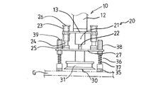
図1に示す実施例1では、前記ロボットハンド11は、ロボットアーム12の先端に取り付けられた支持プレート13等からなり、該支持プレート13の略中央部には昇降シリンダ21等によって吸着手段30を昇降させる昇降手段20が取り付けられている。
【0022】
該昇降手段20は、支持プレート13の中心に昇降シリンダ21を取り付け、昇降シリンダ21の作動によって伸縮自在なシリンダロッド22の先端にブラケット28を介して昇降プレート27が取り付けられている。
【0023】
該昇降プレート27の中心部には吸着手段30として吸着パッド31を設けた。
【0024】
一方、前記支持プレート13の両端には、一対のリニアガイド23、23の筒状部が固定されており、該筒状のリニアガイド23、23の筒状の内部に摺動自在なガイドシャフト24、24が挿通されており、該ガイドシャフト24、24の上端には昇降ストッパー26を設け、下端は取付部材25を介して昇降プレート27の両端に固定されている。
【0025】
このため、昇降シリンダ21の作動によりシリンダロッド22が伸縮すると、前記一対のリニアガイド23によって昇降プレート27がスムーズに昇降できる。
【0026】
前記昇降シリンダ21は、通常シリンダロッドが伸びている状態とし、ハンドリングロボット等に異常が発生した時は、昇降シリンダ21のシリンダロッド22を引っ込め、位置決めのために投入中のガラス板Gとロボットハンドを引き離す。
【0027】
これは、ガラス板Gを搬送するチェーンと共に位置決めガイド3、3も移動しているため、位置決め中にハンドリングロボットが異常停止した時は、ガラス板を釈放して吸着パッド等をガラス板から引き離してやらないと、移動中の位置決めガイドと衝突して破損させてしまう恐れがあるためである。
【0028】
図2に示されるように、前記吸着パッド31は、吸着面の周辺部をゴム製としたが、該周辺部にスポンジ状の押圧部材35を貼着させてガラス板Gとの摩擦力を高めるようにした。
【0029】
また押圧部材35をガラス板Gに押し付けたときに押圧部材35が圧縮されすぎて吸引孔33へのエアの通路を塞ぎ、吸着力が損なわれないように吸着パッド31の内部には複数個のストッパー32、32、・・を設けた。
【0030】
図1、図2に示す実施例1では、吸着パッド31のガラス板との当接面の周辺部にガラス板Gとの摩擦力を利用して押圧移動させるスポンジ製の押圧部材35を貼着したが、図3〜図5に示すように、押圧部材35と吸着パッド31を別々に配置し、吸着パッド31の外側周辺部に複数個の押圧部材35、35、・・を独立して設けるようにしても良い。
【0031】
また、図3〜図5に示す実施例2では、ロボットアーム12の先端に取り付けられたロボットハンド11は前記実施例1に示したものと略同一構造であるが、押圧部材35、35、・・を吸着パッド31の周囲に設けた点で異なるものである。
【0032】
該押圧部材35、35、・・は、昇降プレート27の周辺部に筒状部材38を取り付け、筒状部材38内に押圧ロッド37が上下方向に摺動自在となるように挿通され、押圧ロッド37の上端にはストッパー39を固着し、下端に押圧部材35が取り付けられている。
【0033】
また、押圧部材35と筒状部材38間の押圧ロッド37を囲むようにバネ材36が設けられているので押圧部材35はバネ材36の圧縮による復元力により下方に押圧しようとする力が働く。また、前記ストッパーに39によって押圧ロッド37が筒状部材38より抜け落ちることはない。
【0034】
また、エアテーブル2上で浮上するガラス板Gを位置決めする時は、吸着パッド31を釈放状態とし、昇降シリンダ21のシリンダロッドは常時伸ばした状態とし、ハンドリングロボット等に異常が発生した時は、位置決めのために投入中のガラス板Gとロボットハンドを引き離すために、昇降シリンダ21のシリンダロッド22を引っ込める必要がある。
【0035】
ガラス板Gを吸着し、ハンドリングする時は、押圧部材35を押し、バネ材を圧縮した状態で吸着する。
【0036】
また、ガラス板を位置決めする時には エアテーブル面より少し上空位置で吸着中のガラス板を釈放させると、ガラス板は自重で少し落下し、吸着パッドからは離れるが押圧部材35とは密着している。
【0037】
又は 正規の高さでガラス板を釈放後 ハンドリングロボットを少し上昇させ、吸着パッドとガラス板は離れているが押圧部材35とは密着している状態にしてから位置決めガイドに押しつける。
【0038】
前記押圧部材35はガラス板面との摩擦力の高いスポンジゴム等からなり、ガラス板Gとの摩擦力によってガラス板Gを水平移動を可能とするものである。
に低い位置とすることができる。
【0039】
本発明の位置決め方法及び装置1においては、ガラス板Gを押圧移動手段で位置決めするときに、エアテーブル2上に浮上させたガラス板Gを吸着パッド31で吸着せず、押圧部材35とガラス表面の摩擦力だけでガラス板Gを位置決めガイド3、3に押し付けるように移動させるので、位置決めガイド3、3に当接後、さらに押圧部材35が移動したとしてもハンドの移動する力が前記摩擦力に勝って、押圧部材35がガラス表面上をスリップし、押圧部材35だけが移動することになる。
【0040】
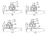
次に、本発明のガラス板の位置決め方法および装置1の実施例1について、その動作を、図6(a)〜(d)に示す。
【0041】
まず、図6(a)に示すように、ハンドリングロボット等によりエアテーブル2の略中央位置に、水平姿勢でフラットなガラス板Gを予め設定した向きに載置する。
【0042】
該ガラス板Gはエアテーブル2の上面に設けた複数の細孔より噴出するエアにてガラス板を浮上させ滑動するが、噴出する圧縮エアは位置決めするガラス板Gを僅かに浮上させるだけの圧力があれば十分である。
【0043】
前記エアテーブル2はエアを噴出しガラス板Gを浮上させた状態で、吸着パッド31の吸引を切って釈放状態とするが、ガラス板Gは下方からのエアと、上方からの吸着パッド31の押付によってエアテーブル2から一定の距離を保って静止している。
【0044】
図6(b)に示すように、吸着パッド31のガラス板Gとの接触面には摩擦係数の大きなスポンジゴム等からなる押圧部材35を貼着しているので、ガラス板Gを押圧部材35で押圧した状態でロボットハンド11を位置決めガイド3、3に向けて移動させるとガラス板Gは位置決めガイド3、3に当接して停止するが、図6(c)に示したように押圧部材35はガラス板Gと当接しているだけなのでさらに位置決めガイド3、3側に滑って移動する。
【0045】
図6(d)に示すように、ガラス板Gを位置決めガイド3、3に押しつづけながら、押圧部材35はガラス板G上を滑り、所定のストローク移動した後停止し、押圧移動手段10によってロボットハンド11は上昇するとガラス板Gの位置決めは完了となる。
【0046】
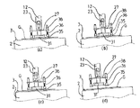
次いで、本発明のガラス板の位置決め方法および装置の実施例2について、その動作を、図7(a)〜(d)に示す。
【0047】
図7(a)に示すように、ハンドリングロボット等によりエアテーブル2の略中央位置に、水平姿勢でフラットなガラス板Gを予め設定した向きに載置する。
【0048】
該ガラス板Gはエアテーブル2の上面に設けた複数の細孔より噴出するエアにてガラス板を浮上させ滑動するが、噴出する圧縮エアは位置決めするガラス板Gを僅かに浮上させるだけの圧力があれば十分である。
【0049】
前記エアテーブル2はエアを噴出しガラス板Gを浮上させた状態で、吸着パッド31の吸引を切って釈放状態とするが、ガラス板Gは下方からのエアと、上方からの吸着パッド31の押付によってエアテーブル2から一定の距離を保って静止している。
【0050】
図7(b)に示すように、ロボットを僅かに上昇させると、ガラス板Gが接触するのが吸着パッドから押圧部材へと変わり、ガラス板と押圧部材の接触面が摩擦係数の大きなゴム等からなるので、ガラス板Gを押圧部材35で押圧した状態でロボットハンド11を位置決めガイド3、3に向けて移動させると、ガラス板Gだけは位置決めガイド3、3に当接して停止するが、図7(c)に示したように押圧部材35はガラス板Gと当接しているだけなのでさらに位置決めガイド3、3側に滑って移動する。
【0051】
図7(d)に示すように、ガラス板Gを位置決めガイド3、3に押しつづけながら、押圧部材35はガラス板G上を滑り、所定のストローク移動した後停止し、押圧移動手段10によってロボットハンド11は上昇するとガラス板Gの位置決めは完了となる。
【0052】
エアテーブル上で浮上しながら位置決めガイドに当接したガラス板Gは、位置決めガイド3、3の移動にあわせて、次工程の所定の場所に移載する。
【0053】
以上好適な実施例について述べたが、本発明はこれに限定されるものではない。
【0054】
ガラス板Gは矩形状を初めとして、三角形状、台形状の異形状のガラス板でも良い。
【0055】
位置決めガイド3の取付位置は、一定速度で搬送される搬送チェーンに固定されたものであっても良いし、エアテーブルに静止状態で固定されたものであっても良い。
【0056】
【発明の効果】
本発明は、シンプルな構造にして、搬送チェーンに取り付けたような遊びやガタを有する位置決めガイドに、ガラス板を確実に精度良く容易に当接させることができる。
【0057】
また、ガラス板を位置決めする速度も速いので生産効率も良く、種々の形状であっても容易に位置決め可能である。
【図面の簡単な説明】
【図1】本発明の実施例1のハンドの側面図。
【図2】本発明の実施例1のハンドの底面図。
【図3】本発明の実施例2のハンドの側面図。
【図4】本発明の実施例2のハンドの底面図。
【図5】本発明の実施例2のハンドの正面図。
【図6】本発明の実施例1の動作(a)〜(d)を説明する側面図。
【図7】本発明の実施例2の動作(a)〜(d)を説明する側面図。
【符号の説明】
G ガラス板
1 位置決め装置
2 エアテーブル
3 位置決めガイド
10 押圧移動手段
11 ロボットハンド
12 ロボットアーム
13 支持プレート
20 昇降手段
21 昇降シリンダ
22 シリンダロッド
23 リニアガイド
24 ガイドシャフト
25 取付部材
26 ストッパー
27 昇降プレート
28 ブラケット
30 吸着手段
31 吸着パッド
32 ストッパー
33 吸引孔
35 押圧部材
36 バネ材
37 押圧ロッド
38 筒状部材
39 ストッパー[0001]
TECHNICAL FIELD OF THE INVENTION
The present invention conveys a flat glass sheet before being subjected to various processing such as bending and surface processing as a glass sheet for a window glass for a vehicle, an industrial glass sheet used for home appliances and industrial equipment, a furniture sheet and the like. The present invention relates to a method and apparatus for positioning on a line.
[0002]
[Prior art]
2. Description of the Related Art Conventionally, many methods and apparatuses for positioning a plate-shaped body such as a glass plate on a transfer line in order to perform processing or the like have been proposed and known.
[0003]
For example, in Japanese Unexamined Patent Application Publication No. 2000-296435 related to an earlier application by the present applicant, a deformed glass is placed in a horizontal posture on a horizontally slidable support table, and the support table is placed on the X axis and the Y axis. The glass is tilted in the direction, the deformed glass is brought closer to a corner portion on the lower side due to the inclination on the support table, and is positioned by contacting stoppers provided on two sides sandwiching the corner. Disclosed is a method of positioning a deformed glass, and further, a sliding means for allowing the deformed glass plate to slide on a support, and slightly raising and inclining one end of the X-axis and the Y-axis of the support, and Abutting means for facilitating the sliding of the support table, and abutting plate members in the vertical and horizontal sides sandwiching a corner portion which is the lower end side of the support base due to the inclination, and abutting against a slipped deformed glass plate comprising a stopper provided near the plate material. Positioning device of the modified glass was disclosed which is characterized in that a part abutment means.
[0004]
Also, in Japanese Patent Application Laid-Open No. Hei 6-247594 by the present applicant, one side on the surface of an air table with a roll conveyor for jetting and floating a deformed glass plate is projected in a transverse direction toward the center of the roll. And a reference pusher provided with a stopper which comes into contact with an end surface of the glass plate and serves as a reference position, and a reciprocating means provided on a cross beam of a gantry provided on the air table at a position facing the reference pusher. A transverse pusher provided with a disc-shaped or square-plate-shaped contact member that protrudes in the transverse direction and presses against the end surface of the glass plate at the lower end of the rod that hangs down from the base, and sandwiches the transverse pusher into the conveyor. A pair of reciprocating means comprising opposed reciprocating means suspended from a bracket which is separated in the transport direction and reciprocally traversed by forward and backward moving means attached to the cross beam; The positioning device of profiled glass provided with a Fischer disclosed a positioner profiled glass, characterized in that a pivoting means allowed to placing horizontally rotating the reciprocating means on said bracket.
[0005]
[Patent Document 1]
JP 2000-296435 A [Patent Document 2]
JP-A-6-247594
[Problems to be solved by the invention]
When a glass sheet for a vehicle is continuously bent and formed, a flat glass sheet cut into a predetermined shape is positioned before being put into a bending furnace, and then sequentially conveyed into the bending furnace by a conveyor.
[0007]
One of the methods for supporting and transporting these glass plates is to position the one edge of the glass plate so as to abut a support member attached to a transport chain or the like while floating the glass plate on an air table. There is a method of transporting while supporting.
[0008]
In this case, since the transport chain is provided in a closed loop shape in a long tunnel-shaped bending furnace, the number of support members that support the glass plate attached to the transport chain also reaches one hundred and several tens, The positioning position of the glass plate is not fixed due to the bending of the conveyed chain, the elongation of the chain, and errors in the mounting positions of many support members.
[0009]
For this reason, when the glass plate is moved by a transfer device such as a robot, and the glass plate is brought into contact with the support member on the transfer line and the positioning is attempted, the support member itself used as the positioning guide is attached to the chain. And positioning is not sufficient.
[0010]
In the method disclosed in
[0011]
Further, the one disclosed in
[0012]
[Means for Solving the Problems]
The present invention is intended to solve the above-mentioned problems, that is, a glass plate is always brought into contact with a positioning guide having a play or play that is attached to a transport chain with a simple structure by fast tact positioning. The purpose is to achieve positioning.
[0013]
That is, according to the present invention, a glass plate supported by suction by a suction pad provided on a hand of a transfer robot or the like is placed in a floating state on an air table that blows air from the upper surface, and after suction of the suction pad is released. By moving the glass plate by the frictional force between the pressing member and the glass plate while bringing the pressing member attached to or adjacent to the peripheral portion of the suction surface of the suction pad into contact with the upper surface of the floating glass plate. A glass plate positioning method characterized in that positioning is performed by bringing an edge of a glass plate into contact with at least two positioning guides provided on one side of an air table.
[0014]
Alternatively, the present invention provides an air table for ejecting air from a plurality of pores provided on an upper surface to make a glass plate floatable, and positioning the edge of the glass plate in contact with one edge side of the air table. At least two positioning guides, suction means comprising suction pads for suction-supporting the upper surface of the glass plate, a pressing member for contacting the upper surface of the glass plate floating by the air table, and a pressing member which can be pressed by the robot hand. And a pressing / moving means for horizontally moving the glass plate on the table by the frictional force of the glass plate.
[0015]
Alternatively, the present invention is the above-described apparatus for positioning a glass plate, wherein a sponge rubber or the like is applied to the glass suction surface of the suction pad as the pressing and moving means.
[0016]
Alternatively, the present invention is characterized in that the pressing and moving means is provided with a pressing member made of a sponge rubber material in a vicinity of a suction pad and capable of being pressed downward by a spring and having a contact portion with a glass plate. Is a positioning device for a glass plate.
[0017]
The glass sheet positioning device according to any of the above, wherein the positioning guide is mounted with a play at the mounting position.
[0018]
BEST MODE FOR CARRYING OUT THE INVENTION
The glass plate
[0019]
In particular, the positioning method and apparatus of the present invention are designed so that the glass sheet G is brought into contact with the positioning guides 3 attached to the transport chain that moves continuously at a constant speed in the bending furnace for bending and strengthening the glass sheet. An effective method and apparatus for positioning.
[0020]
The air table 2 has a plurality of pores on the upper surface thereof, and the compressed air can be ejected from the pores to float the glass plate G.
[0021]
In the first embodiment shown in FIG. 1, the
[0022]
The elevating means 20 has an elevating
[0023]
At the center of the elevating
[0024]
On the other hand, a cylindrical portion of a pair of
[0025]
For this reason, when the
[0026]
The elevating
[0027]
This is because the positioning guides 3 and 3 are also moved together with the chain for transporting the glass plate G. Therefore, when the handling robot stops abnormally during positioning, the glass plate is released and the suction pad and the like are separated from the glass plate. Otherwise, it may collide with the moving positioning guide and cause breakage.
[0028]
As shown in FIG. 2, the peripheral portion of the suction surface of the
[0029]
Further, when the pressing
[0030]
In the first embodiment shown in FIGS. 1 and 2, a pressing
[0031]
In the second embodiment shown in FIGS. 3 to 5, the
[0032]
The
[0033]
Further, since the
[0034]
When positioning the glass plate G floating on the air table 2, the
[0035]
When the glass plate G is sucked and handled, the pressing
[0036]
Also, when positioning the glass plate, if the glass plate being sucked is released slightly above the air table surface, the glass plate falls slightly by its own weight and separates from the suction pad but is in close contact with the pressing
[0037]
Alternatively, after releasing the glass plate at a regular height, the handling robot is slightly raised, and the suction pad and the glass plate are separated from each other, but are brought into close contact with the pressing
[0038]
The pressing
Lower position.
[0039]
In the positioning method and
[0040]
Next, the operation of the glass sheet positioning method and
[0041]
First, as shown in FIG. 6A, a flat glass plate G is placed in a horizontal orientation at a substantially central position of the air table 2 by a handling robot or the like in a preset direction.
[0042]
The glass plate G floats and slides with the air jetted from a plurality of pores provided on the upper surface of the air table 2, and the compressed air jetted has a pressure enough to slightly float the glass plate G to be positioned. Is enough.
[0043]
While the air table 2 blows out air and lifts the glass plate G, the
[0044]
As shown in FIG. 6B, a pressing
[0045]
As shown in FIG. 6 (d), the pressing
[0046]
Next, the operation of the glass sheet positioning method and apparatus according to the second embodiment of the present invention will be described with reference to FIGS.
[0047]
As shown in FIG. 7A, a flat glass plate G is placed in a horizontal orientation at a substantially central position of the air table 2 by a handling robot or the like in a preset direction.
[0048]
The glass plate G floats and slides with the air jetted from a plurality of pores provided on the upper surface of the air table 2, and the compressed air jetted has a pressure enough to slightly float the glass plate G to be positioned. Is enough.
[0049]
While the air table 2 blows out air and lifts the glass plate G, the
[0050]
As shown in FIG. 7 (b), when the robot is slightly raised, the contact of the glass plate G changes from the suction pad to the pressing member, and the contact surface between the glass plate and the pressing member has a large friction coefficient such as rubber. When the
[0051]
As shown in FIG. 7D, the pressing
[0052]
The glass plate G that has come into contact with the positioning guide while floating on the air table is transferred to a predetermined location in the next step in accordance with the movement of the positioning guides 3.
[0053]
Although the preferred embodiment has been described above, the present invention is not limited to this.
[0054]
The glass plate G may be a glass plate having a different shape such as a rectangular shape, a triangular shape, or a trapezoidal shape.
[0055]
The mounting position of the
[0056]
【The invention's effect】
ADVANTAGE OF THE INVENTION This invention can make a glass plate reliably and accurately contact | abut with the positioning guide which has play and backlash attached to the conveyance chain with a simple structure reliably.
[0057]
Further, since the speed of positioning the glass plate is high, the production efficiency is high, and the positioning can be easily performed even in various shapes.
[Brief description of the drawings]
FIG. 1 is a side view of a hand according to a first embodiment of the present invention.
FIG. 2 is a bottom view of the hand according to the first embodiment of the present invention.
FIG. 3 is a side view of a hand according to a second embodiment of the present invention.
FIG. 4 is a bottom view of the hand according to the second embodiment of the present invention.
FIG. 5 is a front view of a hand according to a second embodiment of the present invention.
FIG. 6 is a side view for explaining operations (a) to (d) of the first embodiment of the present invention.
FIG. 7 is a side view for explaining operations (a) to (d) of the second embodiment of the present invention.
[Explanation of symbols]
Claims (5)
Priority Applications (2)
| Application Number | Priority Date | Filing Date | Title |
|---|---|---|---|
| JP2002321467A JP4166077B2 (en) | 2002-11-05 | 2002-11-05 | Glass plate positioning method and apparatus |
| US10/876,655 US7645111B2 (en) | 2002-11-05 | 2004-06-28 | System for putting glass plates to target positions |
Applications Claiming Priority (1)
| Application Number | Priority Date | Filing Date | Title |
|---|---|---|---|
| JP2002321467A JP4166077B2 (en) | 2002-11-05 | 2002-11-05 | Glass plate positioning method and apparatus |
Publications (2)
| Publication Number | Publication Date |
|---|---|
| JP2004155607A true JP2004155607A (en) | 2004-06-03 |
| JP4166077B2 JP4166077B2 (en) | 2008-10-15 |
Family
ID=32802001
Family Applications (1)
| Application Number | Title | Priority Date | Filing Date |
|---|---|---|---|
| JP2002321467A Expired - Fee Related JP4166077B2 (en) | 2002-11-05 | 2002-11-05 | Glass plate positioning method and apparatus |
Country Status (1)
| Country | Link |
|---|---|
| JP (1) | JP4166077B2 (en) |
Cited By (8)
| Publication number | Priority date | Publication date | Assignee | Title |
|---|---|---|---|---|
| JP2012115808A (en) * | 2010-12-03 | 2012-06-21 | Heungbo Tech Co Ltd | Homogeneously kneading apparatus |
| CN104308852A (en) * | 2014-09-11 | 2015-01-28 | 上海大学 | Shifting manipulator of flange plate oil removing machine of filter |
| CN104786228A (en) * | 2014-12-19 | 2015-07-22 | 合肥泰禾光电科技股份有限公司 | Robot vacuum sponge gripper |
| KR20170038002A (en) * | 2014-08-05 | 2017-04-05 | 코닝 인코포레이티드 | End-of-arm tool |
| JP2018069415A (en) * | 2016-11-02 | 2018-05-10 | パナソニックIpマネジメント株式会社 | Electronic apparatus assembling device and electronic apparatus assembling method |
| US10804670B2 (en) | 2016-11-02 | 2020-10-13 | Panasonic Intellectual Property Management Co., Ltd. | Electronic equipment assembly apparatus and electronic equipment assembly method |
| CN112938494A (en) * | 2021-03-01 | 2021-06-11 | 曾小亚 | Carry glass auxiliary device |
| CN114030894A (en) * | 2021-12-21 | 2022-02-11 | 苏州迈为科技股份有限公司 | Method and device for adjusting angle and position of glass |
Families Citing this family (2)
| Publication number | Priority date | Publication date | Assignee | Title |
|---|---|---|---|---|
| CN104229471A (en) * | 2014-08-29 | 2014-12-24 | 苏州巨康缝制机器人有限公司 | Suction disc conveying device |
| CN105923397A (en) * | 2016-06-25 | 2016-09-07 | 蔡崟 | Glass plate rotating mechanism |
-
2002
- 2002-11-05 JP JP2002321467A patent/JP4166077B2/en not_active Expired - Fee Related
Cited By (10)
| Publication number | Priority date | Publication date | Assignee | Title |
|---|---|---|---|---|
| JP2012115808A (en) * | 2010-12-03 | 2012-06-21 | Heungbo Tech Co Ltd | Homogeneously kneading apparatus |
| KR20170038002A (en) * | 2014-08-05 | 2017-04-05 | 코닝 인코포레이티드 | End-of-arm tool |
| KR102418430B1 (en) | 2014-08-05 | 2022-07-07 | 코닝 인코포레이티드 | End-of-arm tool |
| CN104308852A (en) * | 2014-09-11 | 2015-01-28 | 上海大学 | Shifting manipulator of flange plate oil removing machine of filter |
| CN104786228A (en) * | 2014-12-19 | 2015-07-22 | 合肥泰禾光电科技股份有限公司 | Robot vacuum sponge gripper |
| JP2018069415A (en) * | 2016-11-02 | 2018-05-10 | パナソニックIpマネジメント株式会社 | Electronic apparatus assembling device and electronic apparatus assembling method |
| US10804670B2 (en) | 2016-11-02 | 2020-10-13 | Panasonic Intellectual Property Management Co., Ltd. | Electronic equipment assembly apparatus and electronic equipment assembly method |
| CN112938494A (en) * | 2021-03-01 | 2021-06-11 | 曾小亚 | Carry glass auxiliary device |
| CN112938494B (en) * | 2021-03-01 | 2022-08-02 | 庆云茂盛源复合材料有限公司 | Carry glass auxiliary device |
| CN114030894A (en) * | 2021-12-21 | 2022-02-11 | 苏州迈为科技股份有限公司 | Method and device for adjusting angle and position of glass |
Also Published As
| Publication number | Publication date |
|---|---|
| JP4166077B2 (en) | 2008-10-15 |
Similar Documents
| Publication | Publication Date | Title |
|---|---|---|
| JP6253750B1 (en) | Robot hand | |
| JP2921753B2 (en) | Method and apparatus for loading and unloading plate-like work to and from plate processing machine | |
| JP2004155607A (en) | Method and device for positioning glass plate | |
| JP2013039644A (en) | Article holding device | |
| KR101991267B1 (en) | Apparatus for cutting substrate | |
| JP4075002B2 (en) | Overhead traveling car | |
| JP4222849B2 (en) | Automatic loading system of glass sheet into bending furnace | |
| KR20180069677A (en) | Substrate cutting apparatus | |
| CN114132751B (en) | Automatic separation device and separation method for tray | |
| JP5978937B2 (en) | Substrate transfer hand and substrate transfer method | |
| JP4616684B2 (en) | Suction pad and plate inspection equipment | |
| JP2006327819A (en) | Transfer device and transfer method for glass pane | |
| JP4704756B2 (en) | Substrate transfer device | |
| JPH05246689A (en) | Method and device for transporting thin plate | |
| JPH0672577A (en) | Sheet material taking in/taking out device for sheet material machinery | |
| JPH0367929B2 (en) | ||
| CN212397717U (en) | Bending system and supporting device thereof | |
| JP3004239B2 (en) | Plate transfer equipment | |
| CN214217440U (en) | Carrying mechanism | |
| JP2535729B2 (en) | Case transfer method and transfer device | |
| JPS63143135A (en) | Magnetic attraction carrying device | |
| JP6771349B2 (en) | Carrying-out method and carrying-out device and shelf device | |
| JP7158324B2 (en) | Product unloading device and product unloading method | |
| JPH0532331A (en) | Plate separation device | |
| JP3484027B2 (en) | Flat plate unloading device |
Legal Events
| Date | Code | Title | Description |
|---|---|---|---|
| A621 | Written request for application examination |
Free format text: JAPANESE INTERMEDIATE CODE: A621 Effective date: 20050316 |
|
| RD01 | Notification of change of attorney |
Free format text: JAPANESE INTERMEDIATE CODE: A7421 Effective date: 20060424 |
|
| A977 | Report on retrieval |
Free format text: JAPANESE INTERMEDIATE CODE: A971007 Effective date: 20070806 |
|
| A131 | Notification of reasons for refusal |
Free format text: JAPANESE INTERMEDIATE CODE: A131 Effective date: 20070925 |
|
| A521 | Written amendment |
Free format text: JAPANESE INTERMEDIATE CODE: A523 Effective date: 20071015 |
|
| A131 | Notification of reasons for refusal |
Free format text: JAPANESE INTERMEDIATE CODE: A131 Effective date: 20080318 |
|
| A521 | Written amendment |
Free format text: JAPANESE INTERMEDIATE CODE: A523 Effective date: 20080507 |
|
| TRDD | Decision of grant or rejection written | ||
| A01 | Written decision to grant a patent or to grant a registration (utility model) |
Free format text: JAPANESE INTERMEDIATE CODE: A01 Effective date: 20080729 |
|
| A01 | Written decision to grant a patent or to grant a registration (utility model) |
Free format text: JAPANESE INTERMEDIATE CODE: A01 |
|
| A61 | First payment of annual fees (during grant procedure) |
Free format text: JAPANESE INTERMEDIATE CODE: A61 Effective date: 20080729 |
|
| R150 | Certificate of patent or registration of utility model |
Free format text: JAPANESE INTERMEDIATE CODE: R150 |
|
| FPAY | Renewal fee payment (event date is renewal date of database) |
Free format text: PAYMENT UNTIL: 20110808 Year of fee payment: 3 |
|
| FPAY | Renewal fee payment (event date is renewal date of database) |
Free format text: PAYMENT UNTIL: 20110808 Year of fee payment: 3 |
|
| FPAY | Renewal fee payment (event date is renewal date of database) |
Free format text: PAYMENT UNTIL: 20110808 Year of fee payment: 3 |
|
| FPAY | Renewal fee payment (event date is renewal date of database) |
Free format text: PAYMENT UNTIL: 20110808 Year of fee payment: 3 |
|
| FPAY | Renewal fee payment (event date is renewal date of database) |
Free format text: PAYMENT UNTIL: 20120808 Year of fee payment: 4 |
|
| FPAY | Renewal fee payment (event date is renewal date of database) |
Free format text: PAYMENT UNTIL: 20120808 Year of fee payment: 4 |
|
| FPAY | Renewal fee payment (event date is renewal date of database) |
Free format text: PAYMENT UNTIL: 20120808 Year of fee payment: 4 |
|
| FPAY | Renewal fee payment (event date is renewal date of database) |
Free format text: PAYMENT UNTIL: 20130808 Year of fee payment: 5 |
|
| FPAY | Renewal fee payment (event date is renewal date of database) |
Free format text: PAYMENT UNTIL: 20130808 Year of fee payment: 5 |
|
| R250 | Receipt of annual fees |
Free format text: JAPANESE INTERMEDIATE CODE: R250 |
|
| R250 | Receipt of annual fees |
Free format text: JAPANESE INTERMEDIATE CODE: R250 |
|
| R250 | Receipt of annual fees |
Free format text: JAPANESE INTERMEDIATE CODE: R250 |
|
| R250 | Receipt of annual fees |
Free format text: JAPANESE INTERMEDIATE CODE: R250 |
|
| R250 | Receipt of annual fees |
Free format text: JAPANESE INTERMEDIATE CODE: R250 |
|
| LAPS | Cancellation because of no payment of annual fees |