JP2004150256A - Hole drilling device for sewer installation pipe - Google Patents
Hole drilling device for sewer installation pipe Download PDFInfo
- Publication number
- JP2004150256A JP2004150256A JP2003098528A JP2003098528A JP2004150256A JP 2004150256 A JP2004150256 A JP 2004150256A JP 2003098528 A JP2003098528 A JP 2003098528A JP 2003098528 A JP2003098528 A JP 2003098528A JP 2004150256 A JP2004150256 A JP 2004150256A
- Authority
- JP
- Japan
- Prior art keywords
- pipe
- sewage
- cylindrical body
- drilling device
- drilling machine
- Prior art date
- Legal status (The legal status is an assumption and is not a legal conclusion. Google has not performed a legal analysis and makes no representation as to the accuracy of the status listed.)
- Ceased
Links
Images

Abstract
Description
【0001】
【発明の属する技術分野】
本発明は、下水取付管用削孔装置に関し、特に下水管等の欠陥部などから土砂等が流出することにより発生した地下空洞が、下水取付管に近接した位置にある場合に、該下水取付管を利用して効率的に地下空洞を充填するのに使用する、下水取付管用削孔装置に関する。
【0002】
【従来の技術】
道路下の地盤内には、上水道、下水道、或いは都市ガス、電力、通信等の種々の管路が埋設されていることが多く、特に下水道系の管路に破損が発生すると、地下水が管の破損部位から漏入すると共に地盤内の土砂の流失が起こり、地盤内に空洞が発生することがある。このような空洞を放置しておくと、規模が拡大して路面の陥没につながるばかりでなく、交通の障害となるほか、各種の構築物等の破損をも引き起こすことにもなる。
【0003】
そのため路面の異常が発見されたときには、先ず地下空洞の発生が疑われて、舗装面を除去すると共に地下構造の調査が行われ、更に土砂を除去して破損した管路を補修したうえ新たな土砂を充填し、改めて舗装をし直すなどの方法によって、復旧工事を行うのが普通であった。しかしこのように地上から掘削する方法は、大量の土砂を搬出したのち、更に埋め戻す必要があるために工期が長くかかるうえ費用も嵩み、交通の障害となるほか、騒音や粉塵などによる環境汚染の問題もある。
【0004】
そこで本発明者は、前述の問題の発生を避けるために、地上から土砂の掘削を行う代わりに小径の孔を穿設し、この孔を介して地下の空洞部分に直接に地上から土砂等を充填して、安定化させる工法を発明し、特許を得ている (特2733755 、特3037929)。しかしこのような工法でも、地盤内に各種の管路や構築物等が複雑に設置されている場合などでは、前記の小径孔を穿設する工事が容易でない場合があるため、上記の工法の不利を避け得る新規な工法として、地下空洞の発生原因となった欠陥を持つ埋設管等を利用して空洞を充填する方法 (特願2001−257877)を提案している。しかしこの新規工法でも、補修工事の期間中において、埋設管の部分的な使用停止や流路変更などの、仮工事が必要となる場合があり、交通障害や環境汚染の削減にも限度があった。
【0005】
ところで上記のような地下空洞についての最近の調査によれば、その発生原因の3分の2以上を、下水本管に接続される下水取付管に生じた欠陥と、下水本管と該取付管との分岐部分に生じた欠陥とが占めることが判明した。従って、発生した地下空洞の3分の2以上は、下水取付管に近接した位置に存在している、と言うことができる。
【0006】
上記のように、発生した地下空洞が下水取付管に近接した位置にある場合、下水取付管を介して地下空洞の充填工事を実施できれば、下水本管の使用停止や流路変更などの作業による環境への影響や、作業に要する労力や時間等を大幅に削減できると考えられる。そこで、先願の発明技術と同じく地下の構築物等に損傷を与えることなく、また下水本管の機能を殆ど阻害することなく、環境への影響も大幅に削減できる、下水取付管を利用する地下空洞充填工法を提案し、特許出願している (特願2002−200272)。
【0007】
ところで、地表に面して設置された上部枡と地下の下水本管とを繋ぐ下水取付管は、一般に径が15cm程度の細い陶管などで構成されることが多く、また地中に埋設された水道管や電線管などを避けて設けるために、30°,60°,90°というような屈曲部を含んで、急傾斜となるように埋設されていることが多い。そのため従来は、このような埋設状態にある下水取付管に、周囲の土砂を取り除くことなく補修などの工事を施すことは、不可能と考えられていた。
【0008】
【発明が解決しようとする課題】
そこで本発明は、上記のような下水取付管に近接した位置にある地下空洞を充填する工法を、効率的に実施するに適した装置を提供することを目的としたもので、具体的には、下水取付管内に導入して、該下水取付管から地下空洞に充填材を送入する送入孔を、該下水取付管壁面に穿設するための、新規な下水取付管用削孔装置を提供しようとするものである。
【0009】
【課題を解決するための手段】
本発明の下水取付管用削孔装置は、下水取付管内に導入可能な径を有して前後両端部が紡錘形状の筒体内に、該筒体の軸に対して略垂直の回転軸を備えた管壁削孔機を、該回転軸が該筒体の半径方向に進退可能に設けると共に、該管壁削孔機の背側と腹側とに該管壁削孔機を前進方向と後退方向とに付勢する一組のジャッキ装置を対向して設けることで、該回転軸の先端に装着した円筒形切削刃を該筒体の開口から突出でき又撤収できるよう構成してなり、且つ該前後両端部には該筒体を下水取付管内に固定する一対の環状エアパッカーを備えたことを特徴とするものである。
【0010】
本発明の下水取付管用削孔装置において用いられるジャッキ装置としては、特に限定されるものではないが、空気圧ジャッキや油圧ジャッキのような流体圧駆動のジャッキ装置や、電動モータ駆動の機械的ジャッキなども用いることができる。中でも、空気圧ジャッキなどの流体圧ジャッキが好ましく用い得る。
【0011】
また本発明の下水取付管用削孔装置において、前記前後両端部の少なくとも一方に、下水取付管内に導入し又は下水取付管内より撤収するための、移動用牽引索を延設して構成すると、下水取付管用削孔装置の下水取付管への導入や導出が容易となり、曲折の多い下水取付管でも正確な位置に削孔装置を固定できる効果が得られる。
【0012】
また本発明の下水取付管用削孔装置に内蔵して用いられる前記管壁削孔機は、電力駆動又は圧力流体駆動モータにより前記回転型切削刃を回転させるものであってよく、通常利用される電動モータのほかに、圧力水や圧縮空気などを動力源とするタービンなどを、作業現場の環境に応じて適宜に選択して、利用することができ、作業の安全と作業環境の保護とを容易に調和させることができる利点がある。
【0013】
【発明の実施の形態】
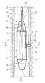
以下、本発明の下水取付管用削孔装置を、図1〜3に基づいて説明する。 図において、Aは地下空洞の近傍に存在している下水取付管であり、Bは、下水取付管Aに設けた地下空洞充填用の土砂等の送入路の開口である。一般的には、上記の目的に利用するのに適した開口Bは、下水取付管Aには設けられていないので、空洞充填工法を適用しようとする地下空洞と、その近傍に存在する下水取付管Aとの状況を充分に調査した上、先ず地下空洞に充填材を送入するに適した開口Bの位置を選定し、その後に下水取付管A内に本発明の下水取付管用削孔装置Cを導入して、下水取付管Aの管壁に開口Bを穿設する必要がある。
【0014】
図に示す下水取付管用削孔装置Cにおいて、1は下水取付管A内に導入できる寸法を有する筒体であり、その前側部1a及び後側部1bは、屈曲して埋設された下水取付管A内にも容易に導入できるように、紡錘形状に細くなっている。これらの前側部1aの前端と、後側部1bの後端には、それぞれ牽引索2a、2bが結合できるようになっていて、これらの牽引索のいずれかを牽引することにより、下水取付管A内に下水取付管用削孔装置Cを引き込み、或いは引き出すことができるようになっている。
【0015】
また、これらの前側部1aと後側部1bの外側には、それぞれ環状のエアパッカー3aと3bが設けてあり、これらの環状エアパッカー3aと3bの内部空間は、加圧空気管3cとそれぞれ連通している。これらの環状エアパッカー3aと3bは、通常は収縮した状態にあるが、加圧空気管3cを通じて地上から送られた空気により膨張し、下水取付管Aの内壁面と下水取付管用削孔装置Cの外面との隙間を封止して、下水取付管用削孔装置Cを下水取付管A内に固定できるように構成されている。
【0016】
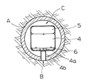
また、筒体1の中央部1c内には、筒体1の軸と垂直方向に向かう回転軸4aを備えた管壁削孔機4が、該回転軸4aが突出している向きに対して背側に設けた空気圧ジャッキ5と、同じく腹側に設けた空気圧ジャッキ6とに挟まれた状態で、回転軸4aの方向に進退が可能に収容されている。そして更に、回転軸4aの先端には、例えば円筒形などの回転型切削刃4bが取り付けられており、中央部1cの壁面に形成された切削窓1dから外に向かって、回転型切削刃4bが出没できるように構成されている。
【0017】
上記の空気圧ジャッキ5と空気圧ジャッキ6とは、それらの内部空間がそれぞれ圧縮空気導管5aと圧縮空気導管6aとに連通していて、これらの圧縮空気導管5aと6aから供給された圧縮空気により膨張して、管壁削孔機4を背側と腹側とから支持するようになっている。そしてまた、空気圧ジャッキ5と空気圧ジャッキ6との一方を膨張させると同時に、他方を収縮させることにより、管壁削孔機4を腹側方向又は背側方向に付勢して、回転軸4aの方向に沿って前進又は後退させることができるようになっている。
【0018】
従って、管壁削孔機4の背側の空気圧ジャッキ5を膨張させるときに、回転軸4aに取り付けた回転型切削刃4bを回転させるようにすると、回転型切削刃4bは前進して切削窓1dから突出し、下水取付管Aの内壁面を削孔して開口Bを形成することができる。次いで、管壁削孔機4の腹側の空気圧ジャッキ6を膨張させると共に、空気圧ジャッキ5を収縮させると、回転軸4aに取り付けた回転型切削刃4bは後退し、開口Bを形成する際に切り取られた下水取付管Aの内壁面の円柱部分を、回転型切削刃4bの中に取り込んだ状態で引き出して、筒体1内に回収することができる。
【0019】
このような本発明の下水取付管用削孔装置Cを用いて、地下空洞を充填するに当たっては、施工対象となる地下空洞と下水管等の埋設管との位置関係を充分調査して、下水取付管を利用して地下空洞の充填を実施することの有利さを先ず確認し、次いで下水取付管に充填材送入用の開口を設けることの適否を検討する。こうした検討結果から、本発明の下水取付管用削孔装置Cを用いることが適切であると判定された後、現地の下水取付管の径に適合した寸法の下水取付管用削装置Cを選定して、地下空洞の充填工事に着手することが、好ましい。
【0020】
地下空洞の充填工事を開始するには、先ず、地下空洞に充填材を送入するために、下水取付管Aにおける開口Bを設ける位置を、上記の調査に基づいて決定する必要がある。そして下水取付管の削孔位置を決定したのち、下水取付管用削孔装置Cを正確に下水取付管の削孔位置に固定するために、測量などの必要な準備を行う。そして更に必要があれば、下水取付管の中に牽引索2aなどを挿通しておき、下水取付管用削孔装置Cを上部枡から下水取付管Aの所定位置に導入して、環状エアパッカー3aと3bを膨張させ、下水取付管用削孔装置Cを正しい削孔位置に固定する。
【0021】
こうして管壁削孔機4の回転型切削刃4bを回転させると共に、空気圧ジャット5を膨張させて、回転型切削刃4bにより下水取付管Aの壁に開口Bを形成する。その後、空気圧ジャッキ6を膨張させて回転型切削刃4b撤収し、次いで環状エアパッカー3aと3bを収縮させた後、下水取付管用削孔装置Cを牽引索2bなどにより引き戻して、上部枡を経由して回収する。
【0022】
更に開口Bの状況を検査して、充填材の送入に支障があるか無いかを確認し、必要があれば、更に充填材送入孔の追加的掘削などを行って、特願2002−200272 で提案した地下空洞充填工法などに従い、地下空洞へ充填材を注入する。そして地下空洞の充填が終わったのち、下水取付管Aの開口Bを充填したうえ封止し、更に開口B部分を含む下水取付管Aの内面を補修し、必要に応じて新たにライニングを施すなどして、下水取付管を利用する地下空洞充填工事を完了する。
【0023】
【発明の効果】
本発明の下水取付管用削孔装置を使用する地下空洞充填工法によれば、比較的に小径で屈曲が著しい下水取付管を利用して、効率的に施工を進めることができるので、工数が少なく且つ工期も短くて済むほか、地上或いは地表に近い位置での作業が多くなり、作業用装置が小型化するばかりでなく、取扱いに伴う作業量も、大幅な軽減が期待される。
しかも路面に損傷を与えることが少なく、工事による環境汚染の恐れも殆どなく、しかも工事費用も削減できる効果がある。
【図面の簡単な説明】
【図1】本発明の下水取付管用削孔装置の構造を説明する縦断面図である。
【図2】本発明の下水取付管用削孔装置のX−X線に沿った縦断面図である。
【図3】下水取付管内に設置した本発明の下水取付管用削孔装置の正面図である。
【符号の説明】
A 下水取付管
B 開口
C 下水取付管用削孔装置
1 筒体
1a 前側部
1b 後側部
1c 中央部
1d 切削窓
2a,2b 牽引索
3a,3b 環状エアパッカー
3c 加圧空気管
4 管壁削孔機
4a 回転軸
4b 回転型切削刃
5 空気圧ジャッキ
5a 圧縮空気導管
6 空気圧ジャッキ
6a 圧縮空気導管[0001]
TECHNICAL FIELD OF THE INVENTION
The present invention relates to a sewage mounting pipe drilling device, and particularly to a sewage mounting pipe when an underground cavity generated by the outflow of earth and sand from a defective portion of the sewage pipe or the like is located near the sewage mounting pipe. TECHNICAL FIELD The present invention relates to a sewage pipe drilling device used to efficiently fill an underground cavity by utilizing a method.
[0002]
[Prior art]
Various pipelines for water supply, sewerage, city gas, electric power, telecommunications, etc. are often buried in the ground under the road, and in particular, when damage occurs to the pipelines of In addition to leaking from the damaged part, soil and soil in the ground may be washed away, and a cavity may be formed in the ground. Leaving such cavities not only increases the scale and leads to the collapse of the road surface, but also hinders traffic and may cause damage to various structures and the like.
[0003]
Therefore, when an abnormality is found on the road surface, it is first suspected that an underground cavity will be generated, and the pavement surface will be removed, and the underground structure will be investigated. It was common practice to rebuild the building by filling it with earth and sand and re-paving it. However, the method of excavating from the ground in this way requires a large amount of sediment to be transported and then backfilled, which requires a long construction time, increases costs, hinders traffic, and reduces the environmental impact of noise and dust. There is also the problem of pollution.
[0004]
Therefore, in order to avoid occurrence of the above-described problem, the present inventor drilled a small-diameter hole instead of excavating earth and sand from the ground, and directly injected earth and sand from the ground into a hollow portion underground through this hole. A method for filling and stabilizing was invented and patented (JP 2733755, JP 3037929). However, even with such a construction method, when various pipes, structures, and the like are installed in the ground in a complicated manner, it may not be easy to construct the small-diameter hole, and thus the disadvantage of the above-described construction method may be difficult. As a new construction method capable of avoiding the problem, a method (Japanese Patent Application No. 2001-257877) of filling a cavity by using a buried pipe or the like having a defect that caused an underground cavity has been proposed. However, even with this new construction method, temporary construction work may be required during the repair work, such as partial suspension of use of buried pipes or a change in the flow path, and there are limits to the reduction of traffic obstacles and environmental pollution. Was.
[0005]
By the way, according to a recent survey on the above-mentioned underground cavities, more than two-thirds of the causes are caused by defects generated in the sewage attachment pipe connected to the sewage main pipe, the sewage main pipe and the attachment pipe. It was found that the defect generated at the branch portion of the occupied portion occupied. Therefore, it can be said that two-thirds or more of the generated underground cavity exists at a position close to the sewage attachment pipe.
[0006]
As described above, if the generated underground cavity is located near the sewage fitting pipe, if the filling work of the underground cavity can be carried out via the sewage fitting pipe, work such as stopping use of the sewage main pipe or changing the flow path It is thought that the impact on the environment and the labor and time required for the work can be significantly reduced. Therefore, similar to the invention technology of the prior application, an underground using a sewage installation pipe can greatly reduce the effect on the environment without damaging underground structures and the like and almost without impairing the function of the sewage main pipe. A cavity filling method has been proposed and a patent application has been filed (Japanese Patent Application No. 2002-200272).
[0007]
By the way, the sewage attachment pipe that connects the upper basin installed on the ground surface and the sewage main pipe under the ground is generally composed of a thin ceramic pipe with a diameter of about 15 cm in general, and is buried underground. In order to avoid water pipes, conduits, and the like, they are often embedded so as to have a steep slope, including bent portions such as 30 °, 60 °, and 90 °. For this reason, it has conventionally been considered impossible to perform repair or other work on such a buried sewage installation pipe without removing the surrounding earth and sand.
[0008]
[Problems to be solved by the invention]
Therefore, the present invention aims to provide an apparatus suitable for efficiently carrying out a method for filling an underground cavity located in a position close to a sewage attachment pipe as described above. To provide a new sewage fitting pipe drilling device for introducing a filler hole into a sewage fitting pipe and introducing a filler from the sewage fitting pipe into an underground cavity in a wall surface of the sewage fitting pipe. What you are trying to do.
[0009]
[Means for Solving the Problems]
The drilling device for a sewage fitting pipe according to the present invention includes a spindle having a diameter that can be introduced into the sewage fitting pipe and having both front and rear ends in a spindle shape, and a rotation axis substantially perpendicular to the axis of the cylinder. A pipe wall drilling machine is provided so that the rotation axis can advance and retreat in the radial direction of the cylindrical body, and the pipe wall drilling machine is provided on the back side and the abdominal side of the tube wall drilling machine in a forward direction and a retreating direction. By providing a set of jack devices opposing to each other, the cylindrical cutting blade attached to the tip of the rotating shaft can be protruded from the opening of the cylindrical body and can be withdrawn, and At both ends, there is provided a pair of annular air packers for fixing the tubular body in the sewage attachment pipe.
[0010]
The jack device used in the sewage pipe drilling device of the present invention is not particularly limited, but a fluid pressure driven jack device such as a pneumatic jack or a hydraulic jack, or a mechanical jack driven by an electric motor. Can also be used. Above all, a fluid pressure jack such as a pneumatic jack can be preferably used.
[0011]
Further, in the drilling device for a sewage mounting pipe of the present invention, at least one of the front and rear ends, at least one of the front and rear ends, is provided with a moving tow line for extending into the sewage mounting pipe or withdrawing from the sewage mounting pipe. It is easy to introduce and take out the drilling device for the mounting pipe into the sewage mounting pipe, and it is possible to obtain an effect that the drilling apparatus can be fixed at an accurate position even in a sewage mounting pipe having many bends.
[0012]
The pipe wall drilling machine used in the drilling device for a sewage mounting pipe of the present invention may be one that rotates the rotary cutting blade by a power drive or a pressure fluid drive motor, and is usually used. In addition to electric motors, turbines powered by pressurized water, compressed air, etc., can be selected and used as appropriate according to the work site environment, and work safety and work environment protection can be achieved. There are advantages that can be easily harmonized.
[0013]
BEST MODE FOR CARRYING OUT THE INVENTION
Hereinafter, a sewage mounting pipe drilling device of the present invention will be described with reference to FIGS. In the figure, A is a sewage attachment pipe existing in the vicinity of the underground cavity, and B is an opening of an inflow passage for soil and the like for filling the underground cavity provided in the sewage attachment pipe A. Generally, an opening B suitable for the above-mentioned purpose is not provided in the sewage mounting pipe A, and therefore, an underground cavity to which the cavity filling method is to be applied and a sewage installation existing in the vicinity thereof. After thoroughly examining the situation with the pipe A, first the position of the opening B suitable for feeding the filler into the underground cavity is selected, and then the sewage pipe drilling device of the present invention is installed in the sewage pipe A. It is necessary to introduce C and perforate the opening B in the pipe wall of the sewer attachment pipe A.
[0014]
In the sewage mounting pipe drilling device C shown in the figure, reference numeral 1 denotes a cylindrical body having a size capable of being introduced into the sewage mounting pipe A, and its front side 1a and rear side 1b are bent and embedded. It is thinned to a spindle shape so that it can be easily introduced into
[0015]
Outside the front part 1a and the rear part 1b,
[0016]
A
[0017]
The
[0018]
Therefore, when the
[0019]
When filling the underground cavity using such a drilling device C for sewage installation pipes of the present invention, the positional relationship between the underground cavity to be constructed and the buried pipes such as sewage pipes is sufficiently investigated, and sewage installation is performed. The advantages of using pipes to fill underground cavities will be confirmed first, and then the feasibility of providing an opening for introducing filler in the sewerage pipe will be examined. From these examination results, after it is determined that it is appropriate to use the sewage mounting pipe drilling device C of the present invention, the sewage mounting pipe drilling device C having a size adapted to the diameter of the local sewage mounting pipe is selected. It is preferable to undertake filling work for the underground cavity.
[0020]
In order to start the filling work of the underground cavity, first, it is necessary to determine the position where the opening B in the sewage mounting pipe A is provided based on the above-mentioned investigation in order to feed the filler into the underground cavity. After determining the drilling position of the sewage fitting pipe, necessary preparations such as surveying are performed in order to accurately fix the drilling device C for sewage fitting pipe at the drilling position of the sewage fitting pipe. If necessary, the towing
[0021]
In this way, the
[0022]
Further, the condition of the opening B is inspected to confirm whether or not the feeding of the filler is obstructed. If necessary, additional excavation of the feeding hole for the filler is performed. The filling material is injected into the underground cavity according to the underground cavity filling method proposed in 2002272. After the filling of the underground cavity is completed, the opening B of the sewage mounting pipe A is filled and sealed, and the inner surface of the sewage mounting pipe A including the opening B portion is repaired, and a new lining is applied as necessary. In this way, underground cavity filling work using sewage attachment pipes is completed.
[0023]
【The invention's effect】
According to the underground cavity filling method using the drilling device for sewage mounting pipe of the present invention, the construction can be efficiently advanced by using the sewage mounting pipe having a relatively small diameter and remarkable bending, so that the number of steps can be reduced. In addition to shortening the construction period, the number of operations on the ground or near the ground surface increases, so that not only the working device is reduced in size, but also the amount of work involved in handling is expected to be significantly reduced.
Moreover, there is little damage to the road surface, there is almost no risk of environmental pollution due to the construction, and the construction cost can be reduced.
[Brief description of the drawings]
FIG. 1 is a longitudinal sectional view illustrating the structure of a drilling device for a sewage installation pipe according to the present invention.
FIG. 2 is a longitudinal sectional view taken along line XX of the drilling device for sewage mounting pipe of the present invention.
FIG. 3 is a front view of the sewage mounting pipe drilling device of the present invention installed in the sewage mounting pipe.
[Explanation of symbols]
Reference Signs List A Sewage attachment pipe B Opening C Sewage attachment pipe drilling device 1 Cylindrical body 1a Front side
Claims (4)
Priority Applications (1)
| Application Number | Priority Date | Filing Date | Title |
|---|---|---|---|
| JP2003098528A JP2004150256A (en) | 2002-09-03 | 2003-04-01 | Hole drilling device for sewer installation pipe |
Applications Claiming Priority (2)
| Application Number | Priority Date | Filing Date | Title |
|---|---|---|---|
| JP2002257555 | 2002-09-03 | ||
| JP2003098528A JP2004150256A (en) | 2002-09-03 | 2003-04-01 | Hole drilling device for sewer installation pipe |
Publications (2)
| Publication Number | Publication Date |
|---|---|
| JP2004150256A true JP2004150256A (en) | 2004-05-27 |
| JP2004150256A5 JP2004150256A5 (en) | 2005-11-04 |
Family
ID=32472923
Family Applications (1)
| Application Number | Title | Priority Date | Filing Date |
|---|---|---|---|
| JP2003098528A Ceased JP2004150256A (en) | 2002-09-03 | 2003-04-01 | Hole drilling device for sewer installation pipe |
Country Status (1)
| Country | Link |
|---|---|
| JP (1) | JP2004150256A (en) |
Cited By (2)
| Publication number | Priority date | Publication date | Assignee | Title |
|---|---|---|---|---|
| CN102374353A (en) * | 2011-11-23 | 2012-03-14 | 宋战修 | Pipe clamp for drilling under pressure of pipeline |
| JP2021025539A (en) * | 2019-07-31 | 2021-02-22 | 日本電信電話株式会社 | Drilling machine |
-
2003
- 2003-04-01 JP JP2003098528A patent/JP2004150256A/en not_active Ceased
Cited By (3)
| Publication number | Priority date | Publication date | Assignee | Title |
|---|---|---|---|---|
| CN102374353A (en) * | 2011-11-23 | 2012-03-14 | 宋战修 | Pipe clamp for drilling under pressure of pipeline |
| JP2021025539A (en) * | 2019-07-31 | 2021-02-22 | 日本電信電話株式会社 | Drilling machine |
| JP7206166B2 (en) | 2019-07-31 | 2023-01-17 | 日本電信電話株式会社 | drilling machine |
Similar Documents
| Publication | Publication Date | Title |
|---|---|---|
| JP2004150256A (en) | Hole drilling device for sewer installation pipe | |
| JP3874095B2 (en) | Wellhead formation method and shield machine when reaching shield machine | |
| JP2005120622A (en) | Construction method of underground structure | |
| JP4024074B2 (en) | Tubing member embedding method | |
| JP2007023546A (en) | Entrance for arrival of jacking pipe, structure of entrance for arrival, and water cut-off construction method for entrance for arrival | |
| JP2005180112A (en) | Ground improvement structure and ground improvement method | |
| JPH04503851A (en) | Improvements in the lining of pipelines or passageways | |
| JP4890390B2 (en) | Entrance seal device | |
| JP3655871B2 (en) | Packer for filling underground cavities | |
| JP3320669B2 (en) | Non-cutting restoration method of service pipe at renewal of underground sewer | |
| JP2007031961A (en) | Obstacle removing method and boring device in pipe jacking method | |
| JP4229356B2 (en) | Face holding method and apparatus for shield machine | |
| KR100977212B1 (en) | Horizontal ring type rotary drill system and method using the same | |
| JP4071260B2 (en) | Tunnel excavator | |
| JPH0514835B2 (en) | ||
| JPH11336479A (en) | Removing and backfilling shield machine and shield tunneling method | |
| KR20030005651A (en) | Pipe laying apparatus | |
| JPH0517354B2 (en) | ||
| JP2006200126A (en) | Device for repairing connecting part of manhole peripheral wall and pipe and repairing construction method using the repairing device | |
| JPS62276197A (en) | Method of replacing construction of buried residual pipe | |
| JP3660284B2 (en) | Underground cavity filling method | |
| JP3366241B2 (en) | Underground pipe laying method and apparatus | |
| JP3359619B2 (en) | Starting method of excavator for propulsion method | |
| JP2023060677A (en) | Tubular member removal method | |
| JP2003097183A (en) | Pipe jacking device of double tube excavation advancing method |
Legal Events
| Date | Code | Title | Description |
|---|---|---|---|
| A521 | Written amendment |
Free format text: JAPANESE INTERMEDIATE CODE: A523 Effective date: 20050905 |
|
| A621 | Written request for application examination |
Free format text: JAPANESE INTERMEDIATE CODE: A621 Effective date: 20050905 |
|
| A977 | Report on retrieval |
Effective date: 20070720 Free format text: JAPANESE INTERMEDIATE CODE: A971007 |
|
| A131 | Notification of reasons for refusal |
Effective date: 20071127 Free format text: JAPANESE INTERMEDIATE CODE: A131 |
|
| A521 | Written amendment |
Effective date: 20071206 Free format text: JAPANESE INTERMEDIATE CODE: A523 |
|
| A01 | Written decision to grant a patent or to grant a registration (utility model) |
Effective date: 20080408 Free format text: JAPANESE INTERMEDIATE CODE: A01 |
|
| A045 | Written measure of dismissal of application |
Free format text: JAPANESE INTERMEDIATE CODE: A045 Effective date: 20080826 |