JP2004148113A - Quick release latch, release handle, and case for carrying portable device - Google Patents
Quick release latch, release handle, and case for carrying portable device Download PDFInfo
- Publication number
- JP2004148113A JP2004148113A JP2003358068A JP2003358068A JP2004148113A JP 2004148113 A JP2004148113 A JP 2004148113A JP 2003358068 A JP2003358068 A JP 2003358068A JP 2003358068 A JP2003358068 A JP 2003358068A JP 2004148113 A JP2004148113 A JP 2004148113A
- Authority
- JP
- Japan
- Prior art keywords
- release
- portable device
- mounting
- handle
- handle portion
- Prior art date
- Legal status (The legal status is an assumption and is not a legal conclusion. Google has not performed a legal analysis and makes no representation as to the accuracy of the status listed.)
- Pending
Links
Images


Classifications
-
- E—FIXED CONSTRUCTIONS
- E05—LOCKS; KEYS; WINDOW OR DOOR FITTINGS; SAFES
- E05C—BOLTS OR FASTENING DEVICES FOR WINGS, SPECIALLY FOR DOORS OR WINDOWS
- E05C19/00—Other devices specially designed for securing wings, e.g. with suction cups
- E05C19/06—Other devices specially designed for securing wings, e.g. with suction cups in which the securing part if formed or carried by a spring and moves only by distortion of the spring, e.g. snaps
-
- G—PHYSICS
- G06—COMPUTING; CALCULATING OR COUNTING
- G06F—ELECTRIC DIGITAL DATA PROCESSING
- G06F1/00—Details not covered by groups G06F3/00 - G06F13/00 and G06F21/00
- G06F1/16—Constructional details or arrangements
- G06F1/1613—Constructional details or arrangements for portable computers
- G06F1/1626—Constructional details or arrangements for portable computers with a single-body enclosure integrating a flat display, e.g. Personal Digital Assistants [PDAs]
-
- G—PHYSICS
- G06—COMPUTING; CALCULATING OR COUNTING
- G06F—ELECTRIC DIGITAL DATA PROCESSING
- G06F1/00—Details not covered by groups G06F3/00 - G06F13/00 and G06F21/00
- G06F1/16—Constructional details or arrangements
- G06F1/1613—Constructional details or arrangements for portable computers
- G06F1/1628—Carrying enclosures containing additional elements, e.g. case for a laptop and a printer
-
- E—FIXED CONSTRUCTIONS
- E05—LOCKS; KEYS; WINDOW OR DOOR FITTINGS; SAFES
- E05B—LOCKS; ACCESSORIES THEREFOR; HANDCUFFS
- E05B65/00—Locks or fastenings for special use
- E05B65/52—Other locks for chests, boxes, trunks, baskets, travelling bags, or the like
-
- G—PHYSICS
- G06—COMPUTING; CALCULATING OR COUNTING
- G06F—ELECTRIC DIGITAL DATA PROCESSING
- G06F2200/00—Indexing scheme relating to G06F1/04 - G06F1/32
- G06F2200/16—Indexing scheme relating to G06F1/16 - G06F1/18
- G06F2200/163—Indexing scheme relating to constructional details of the computer
- G06F2200/1633—Protecting arrangement for the entire housing of the computer
-
- Y—GENERAL TAGGING OF NEW TECHNOLOGICAL DEVELOPMENTS; GENERAL TAGGING OF CROSS-SECTIONAL TECHNOLOGIES SPANNING OVER SEVERAL SECTIONS OF THE IPC; TECHNICAL SUBJECTS COVERED BY FORMER USPC CROSS-REFERENCE ART COLLECTIONS [XRACs] AND DIGESTS
- Y10—TECHNICAL SUBJECTS COVERED BY FORMER USPC
- Y10T—TECHNICAL SUBJECTS COVERED BY FORMER US CLASSIFICATION
- Y10T292/00—Closure fasteners
- Y10T292/08—Bolts
- Y10T292/0894—Spring arm
- Y10T292/0895—Operating means
- Y10T292/0898—Cam
-
- Y—GENERAL TAGGING OF NEW TECHNOLOGICAL DEVELOPMENTS; GENERAL TAGGING OF CROSS-SECTIONAL TECHNOLOGIES SPANNING OVER SEVERAL SECTIONS OF THE IPC; TECHNICAL SUBJECTS COVERED BY FORMER USPC CROSS-REFERENCE ART COLLECTIONS [XRACs] AND DIGESTS
- Y10—TECHNICAL SUBJECTS COVERED BY FORMER USPC
- Y10T—TECHNICAL SUBJECTS COVERED BY FORMER US CLASSIFICATION
- Y10T292/00—Closure fasteners
- Y10T292/08—Bolts
- Y10T292/0894—Spring arm
- Y10T292/0907—Multiple head
Abstract
Description
本発明は、概しては取り付けメカニズムに関するものであり、より詳細には安全取り付け具からコンピュータ等のポータブル装置を取り外すためのクイック解除ラッチ、解除ハンドル、及びポータブル装置の持ち運び用ケースに関するものである。 The present invention relates generally to mounting mechanisms, and more particularly to a quick release latch for releasing a portable device such as a computer from a secure mounting, a release handle, and a carrying case for the portable device.
ポータブルコンピュータ装置は、現在、企業及び消費者に幅広く使用されている。この種のポータブル装置にはノート型及びラップトップコンピュータ、ペンコンピュータ、パーソナルデジタルアシスタント(PDA)及びその他のタイプの通信装置が含まれる。さらに、これらのポータブル装置と一緒に使用するためのあらゆる範囲のアクセサリを入手することができる。これらのポータブル装置は高価であることが多いので、ケース、カバー及び皮製ポータブルケースなどの運搬及び保護用アクセサリが非常に広く出回っている。 Portable computing devices are now widely used by businesses and consumers. Such portable devices include notebook and laptop computers, pen computers, personal digital assistants (PDAs), and other types of communication devices. In addition, a full range of accessories is available for use with these portable devices. Because these portable devices are often expensive, transportation and protection accessories such as cases, covers and leather portable cases are very widespread.
ポータブル装置を持ち運ぶとき、ユーザーは、運搬中の損傷からポータブル装置を保護する例えば皮製ポータブルケースに単にポータブル装置を入れることができる。ポータブルケースによっては、ポータブル装置を中にいれたままポータブル装置を操作できるようになっている。従って、ユーザーはポータブル装置を使用するためにこれをポータブルケースから取り出す必要がない。 When carrying the portable device, the user can simply place the portable device in a portable case, for example made of leather, which protects the portable device from damage during transport. Some portable cases allow the portable device to be operated with the portable device inside. Thus, the user does not need to remove the portable device from the portable case to use it.
残念ながら、典型的なポータブルケースまたは持ち運び用アクセサリは不都合でいくつかの問題点がある。例えば、ポータブルケースによっては、ポータブル装置に確実に取り付けられていないので、ポータブル装置はポータブルケース内を自由に動くことができる。別のポータブルケースはポータブル装置に確実に取り付けられているが、固定メカニズムがポータブル装置の操作を妨害する。例えば、固定メカニズムはディスプレイ画面の一部を覆ったり、ボタンをさえぎってこれを操作できなくしたり、入力/出力ポートへのアクセスまたはCDROM装置など内部装置へのアクセスを妨げる。1つの解決法は、取り付けストラップが画面または操作ボタンを覆わないように装置を大きくすることであるが、より大きな装置を持つことは喜ばれないかも知れない。さらに別のポータブルケースはポータブル装置に確実に取り付けられているが、ポータブル装置から外すのが難しく時間が掛かる。その結果、ユーザーがポータブル装置をポータブルケースから取り外したいとき非常に不便である。 Unfortunately, typical portable cases or carrying accessories are inconvenient and have several problems. For example, some portable cases are not securely attached to the portable device, so that the portable device can move freely within the portable case. Another portable case is securely attached to the portable device, but the securing mechanism prevents operation of the portable device. For example, the locking mechanism may cover a portion of the display screen, block buttons to make it inoperable, or prevent access to input / output ports or internal devices such as CDROM devices. One solution is to make the device larger so that the mounting strap does not cover the screen or operating buttons, but having a larger device may not be pleased. Yet another portable case is securely attached to the portable device, but is difficult and time consuming to remove from the portable device. As a result, it is very inconvenient when the user wants to remove the portable device from the portable case.
従って、ポータブル装置の持ち運び用アクセサリに使用するのに適する取り付けメカニズムを持つことが望ましい。取り付けメカニズムは、ポータブル装置を持ち運び用アクセサリに確実に取り付けて、それによってポータブル装置が閉じられたケースから滑り出て床に落ちることがないようにし、同時に使用中にポータブル装置が動かないようにできなければならない。取り付けメカニズムは、また、ポータブル装置を持ち運び用アクセサリから迅速に簡単に取り外す方法を備えるべきである。 Therefore, it is desirable to have an attachment mechanism suitable for use in portable device carrying accessories. The mounting mechanism allows the portable device to be securely attached to the carrying accessory, thereby preventing the portable device from slipping out of the closed case and falling to the floor, while at the same time preventing the portable device from moving during use. There must be. The mounting mechanism should also provide a quick and easy way to remove the portable device from the carrying accessory.
本発明は、ユーザーが皮製ポータブルケースなどの持ち運び用アクセサリにポータブル装置を確実に取り付けかつ持ち運び用付属品からポータブル装置を迅速に解除できるようにするクイック解除ラッチを含む。本明細書においては特定のポータブル装置及び持ち運び用ポータブルケースに関して説明するが、本発明に含まれるクイック解除ラッチの1つまたはそれ以上の実施態様は、ポータブル装置の確実な取り付け及び迅速な解除が望ましい他のタイプの用途において使用するのに適している。 The present invention includes a quick release latch that allows a user to securely attach a portable device to a carrying accessory such as a leather portable case and quickly release the portable device from the carrying accessory. Although described herein with respect to specific portable devices and portable carrying cases, one or more embodiments of the quick release latch included in the present invention are desirous for secure mounting and quick release of the portable device. Suitable for use in other types of applications.
本発明に含まれる1つの実施態様においては、ユーザーがポータブル装置を使用する可能性を妨害することなくポータブル装置に確実に取り付けられるクイック解除ラッチメカニズムが提供される。例えば、安全取り付け具はディスプレイ画面を遮ることなく、どのボタンの作動も妨害せず、またポータブル装置に取り付けられるどのポートまたは周辺機器へのアクセスも妨げない。
本発明に含まれる1つの実施態様においては、ピボットレス解除ハンドルを含むクイック解除ラッチメカニズムが提供される。解除ハンドルは、同ハンドルが解除運動平面内のあらゆる方向に動かされるとき(回転も含めて)ポータブル装置を取り付けメカニズムから迅速に解除するように動作する。
In one embodiment included in the present invention, a quick release latch mechanism is provided that is securely attached to a portable device without interfering with the user's ability to use the portable device. For example, the safety fitting does not obstruct the display screen, does not interfere with the operation of any buttons, and does not interfere with access to any ports or peripherals attached to the portable device.
In one embodiment included in the present invention, a quick release latch mechanism is provided that includes a pivotless release handle. The release handle operates to quickly release the portable device from the attachment mechanism when the handle is moved in any direction within the release movement plane (including rotation).
1つの実施態様においては、ポータブル装置を安全取り付け具に取り付けかつ安全取り付け具から解除するためのクイック解除ラッチが提供される。クイック解除ラッチは、ポータブル装置の底面に取り外し可能に取り付けることができるバネ負荷された取り付けメカニズムを備える。クイック解除ラッチは、また取り付けメカニズムによって捕捉される解除ハンドルを備え、解除ハンドルは異形エッジを有し、解除平面内におけるあらゆる方向の解除ハンドルの動きによって、異形エッジはポータブル装置から取り付けメカニズムを解除する。 In one embodiment, a quick release latch is provided for attaching and releasing the portable device to and from the safety fixture. The quick release latch has a spring-loaded attachment mechanism that can be removably attached to the bottom of the portable device. The quick release latch also includes a release handle that is captured by the mounting mechanism, the release handle having a profiled edge, and movement of the release handle in any direction within the release plane causes the profiled edge to release the mounting mechanism from the portable device. .
1つの実施態様においては、ポータブル装置を安全取り付け具から解除するための解除メカニズムに使用するための解除ハンドルが提供される。安全取り付け具は少なくとも2つの取り付けクリップを有する取り付けメカニズムを備える。解除ハンドルは取り付けメカニズムによって捕捉される第一のハンドル部分を含む。第一のハンドル部分は、2つの取り付けクリップに隣接する異形エッジを含む。解除ハンドルは、また、ユーザーが操作することができる第二のハンドル部分を含み、第二のハンドル部分は第一のハンドル部分から延び、解除運動平面内におけるあらゆる方向の第二のハンドル部分の動きによって第一のハンドル部分は2つの取り付けクリップを互いに広げさせて安全取り付け具からポータブル装置を解除する。 In one embodiment, a release handle is provided for use with a release mechanism for releasing a portable device from a secure attachment. The safety attachment comprises an attachment mechanism having at least two attachment clips. The release handle includes a first handle portion that is captured by the attachment mechanism. The first handle portion includes a profiled edge adjacent two mounting clips. The release handle also includes a second handle portion operable by a user, the second handle portion extending from the first handle portion for movement of the second handle portion in any direction within the release movement plane. The first handle portion causes the two mounting clips to spread apart, releasing the portable device from the safety mounting.
さらに、本発明は、ポータブル装置を安全取り付け具に取り付けこれから解除するためのクイック解除ラッチを有するポータブル装置の持ち運び用ケースであって、ポータブル装置の底面に取り外し可能に取り付けることができるバネ負荷された取り付けメカニズムと、前記取り付けメカニズムによって捕捉され、異形エッジを有する解除ハンドルとを含み、解除平面内におけるあらゆる方向の前記解除ハンドルの運動が前記異形エッジをして前記取り付けメカニズムを前記ポータブル装置から解除させるようにしたクイック解除ラッチを有するポータブル装置の持ち運び用ケースを提供する。 Further, the present invention is a portable device carrying case having a quick release latch for attaching and releasing the portable device from a safety fixture, the spring loaded device being removably attachable to a bottom surface of the portable device. Including a mounting mechanism and a release handle captured by the mounting mechanism and having a profiled edge, movement of the release handle in any direction within a release plane causes the profiled edge to release the mounting mechanism from the portable device. A portable device carrying case having a quick release latch as described above is provided.
さらに、本発明は、ポータブル装置を安全取り付け具から解除するための解除メカニズムで使用するための解除ハンドルを備え、前記安全取り付け具が少なくとも2つの取り付けクリップを有する取り付けメカニズムを備えたポータブル装置の持ち運び用ケースであって、前記解除ハンドルは、前記取り付けメカニズムによって捕捉される第一のハンドル部を備え、該第一のハンドル部が前記2つの取り付けクリップに隣接する異形エッジを備え、ユーザが操作できる第二のハンドル部を備え、前記第二のハンドル部が前記第一のハンドル部から延び、解除運動平面内におけるあらゆる方向の前記第二のハンドル部の運動が前記第一のハンドル部をして前記2つの取り付けクリップを互いに広げて前記ポータブル装置を前記安全取り付け具から解除させるようにした、ポータブル装置の持ち運び用ケースを提供する。 Further, the present invention comprises a release handle for use with a release mechanism for releasing the portable device from the safety attachment, wherein the safety attachment comprises a mounting mechanism having at least two attachment clips. Wherein the release handle comprises a first handle portion that is captured by the mounting mechanism, the first handle portion having a contoured edge adjacent the two mounting clips, and operable by a user. A second handle portion, the second handle portion extending from the first handle portion, wherein movement of the second handle portion in any direction within a release movement plane causes the first handle portion to move. Spread the two mounting clips together to release the portable device from the safety mounting. And so as to provide a carrying case for portable devices.
本発明の上記の態様及び付随する利点は、下記の添付図面に関連して以下の詳細な説明を参照することによってさらに容易に明らかになるだろう。 The above aspects and attendant advantages of the present invention will become more readily apparent with reference to the following detailed description, taken in conjunction with the accompanying drawings, in which:
本発明は、ユーザーがポータブル装置を確実に取り付けかつこれを皮製ポータブルケースなどの持ち運び用アクセサリから迅速に解除できるようにするクイック解除ラッチメカニズムを含んでいる。クイック解除ラッチメカニズムは、ポータブル装置の確実な取り付け及び迅速な解除が望ましいほぼどのような用途においても使用に適する。 The present invention includes a quick release latch mechanism that allows a user to securely attach a portable device and quickly release it from a carrying accessory such as a leather portable case. The quick release latch mechanism is suitable for use in almost any application where secure mounting and quick release of a portable device is desired.
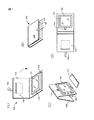
図1は、ディスプレイ画面116を有するポータブル装置102を運搬するためのポータブルケース100の1つの実施態様を示している。ポータブルケース100は本発明に従って構成されるクイック解除ラッチメカニズムを含んでいる。図1において、(A)は開放位置、(B)は閉鎖位置、(C)は操作位置、(D)は取り付け/解除位置を示す。
FIG. 1 shows one embodiment of a
ポータブルケース100は、皮革、厚紙、プラスティック、繊維または他の任意の材料で作ることができる。ポータブル装置102は、パーソナルコンピュータ、PDA、ペンコンピュータまたはその他のどのようなタイプのポータブル装置でもよい。一般にはペンコンピュータは約8″×10″×1″の寸法及び1〜7ポンドの重量を有する。このような用途においては、ポータブルケース100のサイズはこの種のポータブル装置102を収納するものになるだろう。ポータブル装置102はポータブルケース100の内側部分に配置される取り付けプレート104でポータブルケース100に取り付けられる。取り付けプレート104は、プラスティック、金属、厚紙または適切なその他の任意の材料で作ることができる。取り付けプレート104に取り付けられると、ポータブル装置102は安全に運ばれることができる。この実施態様において、ポータブルケース100は、ポータブル装置102を設置/取り外しまたは使用する際は開放位置にされ、ポータブル装置102を運ぶ際は閉鎖位置にされるトップ部106を含む。トップ部106が閉鎖位置のとき、ポータブル装置102は運搬中の損傷から保護される。
The
閉鎖位置のとき、ポータブル装置102の運搬中にトップ部106が閉鎖位置のままでいるようにトップ部106を保持するためにストラップ108が使用される。ポータブルケース100は、ケーブル、ユーザーマニュアルまたは例えばポータブルキーボード112など付加的なアイテムを保管するために使用できる1つまたはそれ以上のポケットまたは保管コンパートメント110も含むことができる。
ストラップ108は、操作中にポータブルケース100を直立位置に保つためにも使用することができる。例えば、トップ部106は、支持構造を形成するように逆方向に折り曲げられ、支持構造は、ストラップ108によって所定の位置に保持される。図1においてこれは「操作」モード(C)として示されている。ポータブルキーボード112は、ポータブル装置102の前に示されており、有線接続、無線接続または光接続を使って装置にインターフェイスすることができる。
図1に示される「取り付け/解除」モード(D)において、ポータブルケース100は、ポータブル装置102を安全取り付け具から解除できるように開いて置かれている。ポータブル装置102をポータブルケース100から解除するために、本発明に従って構成されるピボットレス解除ハンドル114が使用される。ポータブル装置102は、使用のために取り外した後、ポータブル装置102を持ち運ぶときにはポータブルケースに再び取り付けることができる。取り付けメカニズムはポータブルケースをポータブル装置102の裏面に取り付けるので、ポータブル装置102のディスプレイ、ボタンまたは周辺機器へのアクセスを妨害するストラップまたはその他の取り付け上の特徴はない。
When in the closed position,
The
In the "attach / release" mode (D) shown in FIG. 1, the
図2は、取り付けプレート104の詳細図である。取り付けプレート104は、ポータブル装置102の底面と接触する平らな上面208を有する。取り付けメカニズムは取り付けプレート104の底面210に取り付けられる。取り付けメカニズムの一部として、アラインメントピン202が取り付けプレート104を貫通しており、取り付けメカニズムを取り付けプレート104に固定して設置中に取り付けプレート104をポータブル装置102の底面と整合させるために使用される。アラインメントピン202は、また、ポータブル装置102が取り付けプレート104に取り付けられるときにポータブル装置102が過剰に動かないようにするためにも役立つ。取り付けクリップ204も取り付けプレート104を貫通しており、ポータブル装置102の底面にある対応するクリップ受けに留められる。このようにして、ポータブル装置102が取り付けプレート104に取り付けられると、取り付けクリップ204はポータブル装置102をしっかりと保持し、アラインメントピン202はポータブル装置102がスリップまたはスライドするのを防ぐ。
FIG. 2 is a detailed view of the mounting
図2にはクイック解除ハンドル206の一部が示されている。解除ハンドル206は、取り付けプレート104の下に延びているので、図2においては完全に見ることはできない。解除ハンドル206はポータル装置102を取り付けプレート104から迅速に解除するために取り付けクリップ204を操作するために使用される。1つの実施態様において、解除ハンドル206は、取り付けクリップ204を相互に広げるように作動するので、取り付けクリップ204はポータブル装置102の対応するクリップ受けとかみ合わなくなる。取り付けクリップ204がクリップ受けから外れると、ポータブル装置102を取り付けプレート204から取り外すことができる。取り付けクリップ204及び解除ハンドル206の動作については後にさらに詳しく論じる。
FIG. 2 shows a part of the
図3は、取り付けプレート104の底面210の詳細図である。この図においては、解除ハンドル206及びクリップカバー302の完全図を見ることができる。解除ハンドル206は、同解除ハンドルを簡単に操作できるようにするためにユーザーが掴むことができる領域を提供する小さい開口(図には304で示されている)を含んでいる。解除ハンドル206は、また、取り付けクリップ204を操作するために使用される異形エッジ306も含む。解除ハンドル206及び異形エッジ306については本明細書の別の部分で詳しく論じる。
FIG. 3 is a detailed view of the
クリップカバー302は複数の機能を有する。まず、クリップカバー302は、取り付けクリップ204及びその関連メカニズムを所定の位置に保持するように作用する。従って、取り付けクリップ204は、取り付けプレート104の底面210に保持され、取り付けプレート104の開口を通り抜けて取り付けプレート104の上面208に突き出す。
The
第二に、クリップカバー302は、解除ハンドル206がクリップカバー302と取り付けプレート104の底面210の間に捕えられるように解除ハンドル206を捕捉するように作用する。さらに、解除ハンドル206は、同ハンドルの異形エッジ306がそれぞれ取り付けクリップ204に隣接するように取り付けクリップ204の間にも捕捉される。
Second, the
クイック解除ハンドル206が上記の通り捕捉位置にあるとき、解除ハンドル206は、矢印308で示される通り前後にまた矢印310で示される通り左右に自由に動くことができる。従って、解除ハンドル206は、取り付けプレート104に平行の運動平面上で任意の組み合わせの方向に動くことができる。この運動平面は以後解除平面と呼ばれる。解除平面上における解除ハンドル206の動きは取り付けクリップ204を互いに広げ、取り付けクリップ204をポータブル装置102の底面に配置されるクリップ受けから外すので、ポータブル装置102を取り付けプレート104から解除する。後で説明する通り、解除ハンドル206は、右回り及び左回りに回転して同じ機能を得ることもできる。
When the
図4は、図3に示される本発明の実施態様の構成要素の分解斜視図である。この図には、取り付けプレート104の開口402が示されている。開口402は、取り付けクリップ204がポータブル装置102に設けられるクリップ受けとかみ合うことができるように、取り付けクリップ204が取り付けプレート104の反対側に通り抜けることができるようにする。アラインメントピン202は整合を行い、またクリップカバー302を取り付けプレート104に固定することによって、解除ハンドル206を捕捉する。
FIG. 4 is an exploded perspective view of the components of the embodiment of the present invention shown in FIG. In this figure, an
取り付けクリップ204は、取り付けクリップ204を互いに向かって引き寄せるバネ張力を与えるクリップメカニズム404の一部である。解除ハンドル206の操作は取り付けクリップ204を相互に離れさせる(エッジ306の形状のため)ので、それによって、取り付けクリップ204がポータブル装置102のクリップ受けから外れることができるようにする。
The mounting
図5は、本発明に従って構成される取り付けクリップメカニズム404の1つの実施態様の一部の詳細図である。このメカニズム404は、取り付けクリップ204、バネ502及びクリップトラック504を含む。バネ502は、両方の取り付けクリップ204に取り付けられ、取り付けクリップ204を引き寄せる内向きの力を働かせる。取り付けクリップ204及びバネ502はクリップトラック504に取り付けられる。
FIG. 5 is a detailed view of a portion of one embodiment of a mounting
クリップトラック504は、取り付けクリップ204がポータブル装置102の底に配置されるクリップ受けとかみ合ったりこれから外れることができるように取り付けクリップ204を選択された距離だけ近づいたり離れたりできるようにする。クリップトラック504は、取り付けクリップ204が完全に引き寄せられるのを防ぎ、かつ取り付けクリップ204がクリップトラックから外れるほど広がるのを防ぐ、付加的特性(図には示されていない)を含む。クリップメカニズムの1つの実施態様が図5に示されているが、同様の機能を果たすことを条件として他のタイプのメカニズムまたは他の取り付けクリップの配列を代わりとすることができる。従って、本発明の実施態様は図5のクリップメカニズムの使用に限定されない。
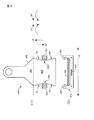
図6は、解除ハンドル206が解除平面内で任意の方向に動かされるとき解除ハンドル206の異形エッジ306がどのように取り付けクリップ204を広げるように作用するかを示すために、解除ハンドル206及び取り付けクリップ204の上面608(A)及び端面610(B)機能図を示している。図6は、また、取り付けクリップ204が、取り付けクリップ204を互いに引き寄せるバネ張力602を含むクリップメカニズム404の一部であることを示している。Rは解除平面の方向である。
FIG. 6 shows the
解除ハンドル206は、プラスティック、金属、厚紙または他の適切なほぼどのような材料からも構成することができる。解除ハンドル206は2つの領域に分けることができる。第一の領域は、操作中ユーザーが解除ハンドル206を使えるようにするためのハンドルを持つハンドル部604である。第二の領域は、取り付けクリップ204を広げるように設計される異形エッジ306を含む異形部606である。異形エッジ306は、エッジE1、E2、E3、E4として示されている。解除ハンドル206が解除平面内であらゆる方向に動かされると、異形エッジ306は、クリップメカニズム404に含まれるバネ張力を上回ることによって取り付けクリップ204を互いに広げるように作用する。
The release handle 206 can be constructed from plastic, metal, cardboard, or almost any other suitable material. Release handle 206 can be divided into two regions. The first area is a
例えば、解除ハンドル206を方向(D1)に動かすと、異形エッジE1及びE4は外向きの圧力を取り付けクリップ204に加え、それによって取り付けクリップ204を互いに広げる。同様に方向(D2)に動かすと、異形エッジE2及びE3は取り付けクリップ204に外向きの圧力を加え、それによって取り付けクリップを互いに広げる。
For example, when the
解除ハンドル206はクリップカバー302(図6には示されていない)及び取り付けクリップ204によって捕捉されているので、解除ハンドル206を方向(D3及びD4)に動かすと、解除ハンドル206は回転運動で動く。従って、解除ハンドル206を方向(D3)に動かすと右回りの回転を生じ、その結果異形エッジE2及びE4が取り付けクリップ204に外向きの圧力を加え、それによって取り付けクリップ204を互いに広げる。同様に、解除ハンドル206を方向(D4)に動かすと左周りの回転を生じ、その結果異形エッジE1及びE3が取り付けクリップ204に外向きの圧力を加え、それによって取り付けクリップ204を互いに広げる。
Since the
また、解除ハンドル206の回転を防ぐために充分な力が加えられる場合には解除ハンドル206を回転させずにD3またはD4の方向に動かすことができる。これは望ましい方法ではないが、解除ハンドル206をこのように動かすことによっても、一方の取り付けクリップ204(運動方向にあるクリップ)に外向きの圧力を加え、それによって、取り付けクリップ204を互いに広げる。例えば、解除ハンドル206を回転なしに方向(D3)に動かすと、エッジE3及びE4はこれらが接する取り付けクリップ204に外向きの圧力を加え、それによって取り付けクリップ204を互いに広げる。
When a sufficient force is applied to prevent the rotation of the
図7は、取り付けクリップ204がポータブル装置706(102)の底面に配置されるクリップ受け702にどのように取り付けられるかを示している。明確にするために、1つの取り付けクリップ204のみの動作が図7に示されている。取り付けクリップ204は、クリップ受け702に取り付けられるために取り付けプレート104の開口708を貫通する。取り付けクリップ204は、設置中にポータブル装置706によって加えられる下向きの力714が取り付けクリップ204を広げ、それによって取り付けクリップ204がクリップ受け702の中に入って所定の位置にロックしてポータブル装置706を確実に保持できるようにする先細エッジ712を含む。上記の設置プロセスは、図1に示されるクイック解除ラッチを有するポータブルケース100にポータブル装置102をロックするために使用することができる。
FIG. 7 shows how the
取り付けクリップ204がクリップ受け702内の所定の位置にロックされた後取り付けクリップ204を解除するためには、ユーザーは解除ハンドル206を動かせばよい。解除ハンドル206は、前述の通り取り付けクリップ204を広げるように作用する。従って、本発明に従ってクイック解除ラッチを使用して、ユーザーは、ポータブル装置102を安全取り付け具に迅速に取り付けることができる。安全取り付け具は皮製ポータブルケース100などの持ち運び用アクセサリの一部とすることができる。ポータブル装置の運搬中、取り付けクリップ204は、ポータブル装置を確実に掴んでいるので、ポータブル装置はポータブルケース内で動いたりスライドしたりしない。ユーザーがポータブル装置を外そうとするとき、ユーザーは、解除平面内のほぼどの方向にもクイック解除ハンドル206を動かして、取り付けクリップ204を広げてポータブル装置から取り付けクリップを外して、ポータブル装置が安全取り付け具から取り外せるようにすることができる。
To release the mounting
アラインメントピン202を使って取り付けプレート104に取り付けられるクリップカバー302も図7に示されている。アラインメントピン202は取り付けプレート204をポータブル装置に整合するように作用するので、取り付けクリップ204は設置プロセス中簡単に所定の位置にロックする。例えば、アラインメントピン202は、ポータブル装置の底面に配置されるアラインメントホール708と整合する。設置中、アラインメントピン202及びアラインメントホール708が整合すると、ユーザーは、取り付けクリップ204がクリップ受け702にロックするまでポータブル装置を取り付けプレート104に押し付けることができる。取り付けクリップ204がロックされると、ポータブル装置は持ち運び用アクセサリの一部である取り付けプレート104に取り付けられる。
A
本発明に従って、ポータブル装置は、取り付けクリップ204及びクリップ受け702によって取り付けプレート104に取り付けられる。このように、ポータブル装置を取り付けプレート204に保持する手段またはメカニズムは他にはない。そのため、ポータブル装置のディスプレイ画面、ボタン及び周辺機器は妨げられることがなく、自由にアクセスできる。従って、ポータブル装置は、取り付け状態のときに完全に機能し、ポータブル装置を持ち運び用アクセサリから取り外すことなくユーザーはこれを操作することができる。
In accordance with the present invention, the portable device is attached to the mounting
図8は、本発明に従って構成されるピボットレス解除ハンドル800の別の実施態様を示している。ピボットレス解除ハンドル800は、カムスロット802を含む。カムスロット802は、取り付けクリップの動き及びタイミングを無限に変動できるようにするためにカムスロット内で動作するピン(図には示されていない)上でピボットレス解除ハンドルを案内することによって作用する。例えば、カムスロットを適切な形状にすることによって、2つの解除ポイントを持つことができる。第一の解除ポイントは、ポータブルケースの中で装置が回転できるようにポータブル装置を部分的に解除する。第二の解除ポイントはポータブル装置の取り外しを可能にする。内部カム形状だけを使用するか外部カムエッジと合わせて使用することもできる。このように、本発明に含まれる1つまたはそれ以上の実施態様において、ポータブル装置を安全取り付け具から迅速に解除するように作用するピボットレス解除ハンドルを提供するために異形エッジまたはカムスロットエッジが使用される。
FIG. 8 shows another embodiment of a pivotless release handle 800 constructed in accordance with the present invention. Pivotless release handle 800 includes a
以上説明した例は下記の特徴を含むものである。
(付記1) ポータブル装置を安全取り付け具に取り付けこれから解除するためのクイック解除ラッチであって、
ポータブル装置の底面に取り外し可能に取り付けることができるバネ負荷された取り付けメカニズムと、
前記取り付けメカニズムによって捕捉され、異形エッジを有する解除ハンドルとを含み、解除平面内におけるあらゆる方向の前記解除ハンドルの運動が前記異形エッジをして前記取り付けメカニズムを前記ポータブル装置から解除させるようにしたクイック解除ラッチ。
The example described above includes the following features.
(Appendix 1) A quick release latch for attaching a portable device to a safety mount and releasing it from
A spring-loaded attachment mechanism that can be removably attached to the bottom of the portable device;
A release handle captured by the mounting mechanism and having a profiled edge, wherein movement of the release handle in any direction within a release plane causes the profiled edge to release the mounting mechanism from the portable device. Release latch.
(付記2) 前記取り付けメカニズムが2つの取り付けクリップを使って前記ポータブル装置に取り付けられる付記1に記載のクイック解除ラッチ。
(付記3) 前記解除ハンドルが前記2つの取り付けクリップの間に捕捉される付記2に記載のクイック解除ラッチ。
(付記4) 前記異形エッジが前記2つの取り付けクリップと整合している付記3に記載のクイック解除ラッチ。
(付記5) 前記取り付けクリップがバネにより負荷され、前記解除ハンドルの動きが前記2つの取り付けクリップを互いに広げさせて前記ポータブル装置を前記安全取り付け具から解除するように作用する付記4に記載のクイック解除ラッチ。
(Supplementary note 2) The quick release latch according to supplementary note 1, wherein the attachment mechanism is attached to the portable device using two attachment clips.
(Supplementary note 3) The quick release latch according to
(Supplementary note 4) The quick release latch according to
(Supplementary note 5) The quick fitting according to
(付記6) ポータブル装置を安全取り付け具から解除するための解除メカニズムで使用するための解除ハンドルであって、前記安全取り付け具が少なくとも2つの取り付けクリップを有する取り付けメカニズムを備えたものにおいて、
前記取り付けメカニズムによって捕捉される第一のハンドル部を備え、該第一のハンドル部が前記2つの取り付けクリップに隣接する異形エッジを備え、
ユーザーが操作できる第二のハンドル部を備え、前記第二のハンドル部が前記第一のハンドル部から延び、解除運動平面内におけるあらゆる方向の前記第二のハンドル部の運動が前記第一のハンドル部をして前記2つの取り付けクリップを互いに広げて前記ポータブル装置を前記安全取り付け具から解除させるようにした解除ハンドル。
(Supplementary note 6) A release handle for use with a release mechanism for releasing a portable device from a safety attachment, wherein the safety attachment comprises an attachment mechanism having at least two attachment clips.
A first handle portion captured by the mounting mechanism, the first handle portion including a profiled edge adjacent the two mounting clips;
A second handle portion operable by a user, the second handle portion extending from the first handle portion, wherein movement of the second handle portion in any direction in a release movement plane is the first handle portion. A release handle adapted to unfold the two mounting clips together to release the portable device from the safety mounting.
(付記7) ポータブル装置を安全取り付け具に取り付けこれから解除するためのクイック解除ラッチを有するポータブル装置の持ち運び用ケースであって、ポータブル装置の底面に取り外し可能に取り付けることができるバネ負荷された取り付けメカニズムと、前記取り付けメカニズムによって捕捉され、異形エッジを有する解除ハンドルとを含み、解除平面内におけるあらゆる方向の前記解除ハンドルの運動が前記異形エッジをして前記取り付けメカニズムを前記ポータブル装置から解除させるようにしたクイック解除ラッチを有するポータブル装置の持ち運び用ケース。 (Supplementary note 7) A carrying case for a portable device having a quick release latch for attaching and releasing the portable device to and from a safety fixture, wherein the spring loaded attachment mechanism is removably attachable to a bottom surface of the portable device. And a release handle captured by the mounting mechanism and having a profiled edge, such that movement of the release handle in any direction in a release plane causes the profiled edge to release the mounting mechanism from the portable device. Carrying case for portable device having a quick release latch.
(付記8) ポータブル装置を安全取り付け具から解除するための解除メカニズムで使用するための解除ハンドルを備え、前記安全取り付け具が少なくとも2つの取り付けクリップを有する取り付けメカニズムを備えたポータブル装置の持ち運び用ケースであって、前記解除ハンドルは、前記取り付けメカニズムによって捕捉される第一のハンドル部を備え、該第一のハンドル部が前記2つの取り付けクリップに隣接する異形エッジを備え、ユーザが操作できる第二のハンドル部を備え、前記第二のハンドル部が前記第一のハンドル部から延び、解除運動平面内におけるあらゆる方向の前記第二のハンドル部の運動が前記第一のハンドル部をして前記2つの取り付けクリップを互いに広げて前記ポータブル装置を前記安全取り付け具から解除させるようにした、ポータブル装置の持ち運び用ケース。 (Supplementary note 8) A carrying case for a portable device comprising a release handle for use with a release mechanism for releasing the portable device from the safety attachment, wherein the safety attachment comprises an attachment mechanism having at least two attachment clips. Wherein the release handle includes a first handle portion that is captured by the mounting mechanism, the first handle portion includes a contoured edge adjacent to the two mounting clips, and a second user-operable. The second handle portion extends from the first handle portion, and movement of the second handle portion in any direction in a release movement plane causes the first handle portion to move to the second handle portion. Two mounting clips spread apart to release the portable device from the safety mounting Unishi was, carrying case for portable devices.
本発明は、ポータブルコンピュータ装置を安全取り付け具から解除するためのクイック解除ラッチを含む。上に説明される実施態様は本発明の例であり、本発明の範囲を特に説明される実施態様に限定するためのものではない。従って、本発明の1つまたはそれ以上の実施態様が図解され説明されているが、本発明の精神または基本的特徴から逸脱することなく本発明において様々な変更を加えることができることが分かるだろう。従って、本明細書における開示及び説明は例示的なものであり、請求の範囲において示される本発明の範囲を限定するためのものではない。 The present invention includes a quick release latch for releasing a portable computing device from a secure mount. The embodiments described above are examples of the present invention and are not intended to limit the scope of the present invention to the specifically described embodiments. Thus, while one or more embodiments of the present invention have been illustrated and described, it will be appreciated that various changes can be made in the present invention without departing from the spirit or essential characteristics of the invention. . Accordingly, the disclosures and descriptions herein are intended to be illustrative, but not limiting, of the scope of the invention, which is set forth in the following claims.
100…ポータブルケース
102…ポータブル装置
104…取り付けプレート
108…ストラップ
114…ピボットリリースハンドル
202…アライメントピン
204…取り付けクリップ
206…解除ハンドル
404…取り付けクリップ機構
502…バネ
702…クリップ受け
100… Portable case
102… Portable device
104… Mounting plate
108… Strap
114… Pivot release handle
202… Alignment pin
204… Mounting clip
206 ... release handle
404… Mounting clip mechanism
502… Spring
702… Clip receiver
Claims (5)
ポータブル装置の底面に取り外し可能に取り付けることができるバネ負荷された取り付けメカニズムと、
前記取り付けメカニズムによって捕捉され、異形エッジを有する解除ハンドルとを含み、解除平面内におけるあらゆる方向の前記解除ハンドルの運動が前記異形エッジをして前記取り付けメカニズムを前記ポータブル装置から解除させるようにしたクイック解除ラッチ。 A quick release latch for attaching and releasing the portable device from the safety fixture,
A spring-loaded attachment mechanism that can be removably attached to the bottom of the portable device;
A release handle captured by the mounting mechanism and having a profiled edge, wherein movement of the release handle in any direction within a release plane causes the profiled edge to release the mounting mechanism from the portable device. Release latch.
前記取り付けメカニズムによって捕捉される第一のハンドル部を備え、該第一のハンドル部が前記2つの取り付けクリップに隣接する異形エッジを備え、
ユーザーが操作できる第二のハンドル部を備え、前記第二のハンドル部が前記第一のハンドル部から延び、解除運動平面内におけるあらゆる方向の前記第二のハンドル部の運動が前記第一のハンドル部をして前記2つの取り付けクリップを互いに広げて前記ポータブル装置を前記安全取り付け具から解除させるようにした解除ハンドル。 A release handle for use with a release mechanism for releasing a portable device from a safety attachment, said safety attachment comprising an attachment mechanism having at least two attachment clips.
A first handle portion captured by the mounting mechanism, the first handle portion including a profiled edge adjacent the two mounting clips;
A second handle portion operable by a user, the second handle portion extending from the first handle portion, wherein movement of the second handle portion in any direction in a release movement plane is the first handle portion. A release handle adapted to unfold the two mounting clips together to release the portable device from the safety mounting.
ポータブル装置の底面に取り外し可能に取り付けることができるバネ負荷された取り付けメカニズムと、
前記取り付けメカニズムによって捕捉され、異形エッジを有する解除ハンドルとを含み、解除平面内におけるあらゆる方向の前記解除ハンドルの運動が前記異形エッジをして前記取り付けメカニズムを前記ポータブル装置から解除させるようにしたクイック解除ラッチを有するポータブル装置の持ち運び用ケース。 A carrying case for a portable device having a quick release latch for attaching and releasing the portable device from a safety fixture, the portable device comprising:
A spring-loaded attachment mechanism that can be removably attached to the bottom of the portable device;
A release handle captured by the mounting mechanism and having a profiled edge, wherein movement of the release handle in any direction within a release plane causes the profiled edge to release the mounting mechanism from the portable device. A carrying case for a portable device having a release latch.
前記解除ハンドルは、
前記取り付けメカニズムによって捕捉される第一のハンドル部を備え、該第一のハンドル部が前記2つの取り付けクリップに隣接する異形エッジを備え、
ユーザが操作できる第二のハンドル部を備え、
前記第二のハンドル部が前記第一のハンドル部から延び、解除運動平面内におけるあらゆる方向の前記第二のハンドル部の運動が前記第一のハンドル部をして前記2つの取り付けクリップを互いに広げて前記ポータブル装置を前記安全取り付け具から解除させるようにした、ポータブル装置の持ち運び用ケース。 A carrying case for a portable device, comprising: a release handle for use with a release mechanism for releasing a portable device from a safety attachment, wherein the safety attachment comprises an attachment mechanism having at least two attachment clips.
The release handle is
A first handle portion captured by the mounting mechanism, the first handle portion including a profiled edge adjacent the two mounting clips;
A second handle portion that can be operated by a user,
The second handle portion extends from the first handle portion, and movement of the second handle portion in any direction within a release movement plane causes the first handle portion to spread the two mounting clips together. A carrying case for the portable device, wherein the portable device is released from the safety attachment.
Applications Claiming Priority (1)
| Application Number | Priority Date | Filing Date | Title |
|---|---|---|---|
| US10/274,821 US6814377B2 (en) | 2002-10-19 | 2002-10-19 | Computer quick release latch |
Publications (1)
| Publication Number | Publication Date |
|---|---|
| JP2004148113A true JP2004148113A (en) | 2004-05-27 |
Family
ID=32093150
Family Applications (1)
| Application Number | Title | Priority Date | Filing Date |
|---|---|---|---|
| JP2003358068A Pending JP2004148113A (en) | 2002-10-19 | 2003-10-17 | Quick release latch, release handle, and case for carrying portable device |
Country Status (2)
| Country | Link |
|---|---|
| US (1) | US6814377B2 (en) |
| JP (1) | JP2004148113A (en) |
Cited By (2)
| Publication number | Priority date | Publication date | Assignee | Title |
|---|---|---|---|---|
| JP2011528503A (en) * | 2008-07-15 | 2011-11-17 | トムソン ライセンシング | Electronic device and its disassembly and release tool |
| KR101163981B1 (en) | 2010-10-11 | 2012-07-09 | 주식회사 뉴빛 | A case of a portable terminal with a function of supporting that |
Families Citing this family (23)
| Publication number | Priority date | Publication date | Assignee | Title |
|---|---|---|---|---|
| US20060026807A1 (en) * | 2003-08-07 | 2006-02-09 | Carnevali Jeffrey D | Quick release mounting apparatus |
| US7571522B2 (en) * | 2003-08-07 | 2009-08-11 | Carnevali Jeffrey D | Quick draw cradle apparatus |
| EP1619576A1 (en) * | 2004-07-23 | 2006-01-25 | VAC Corporation | Tablet PC assembly |
| US20060018089A1 (en) * | 2004-07-23 | 2006-01-26 | Chun-Chien Chou | Notebook type keyboard apparatus |
| US7551458B2 (en) * | 2005-05-24 | 2009-06-23 | Carnevali Jeffrey D | Secure universal mounting apparatus |
| CN2821662Y (en) * | 2005-07-02 | 2006-09-27 | 鸿富锦精密工业(深圳)有限公司 | Casing locking device |
| US7523528B2 (en) * | 2005-07-28 | 2009-04-28 | Carnevali Jeffrey D | Thumb release mounting apparatus |
| US7647676B2 (en) * | 2005-07-28 | 2010-01-19 | Carnevali Jeffrey D | Thumb release mounting apparatus |
| US7988106B2 (en) * | 2007-02-23 | 2011-08-02 | Carnevali Jeffrey D | Adaptive mounting structure |
| US8091850B2 (en) * | 2007-05-31 | 2012-01-10 | Carnevali Jeffrey D | Quick release electronics platform |
| US7823844B2 (en) * | 2007-05-31 | 2010-11-02 | Carnevali Jeffrey D | Quick release electronics platform |
| US8074951B2 (en) * | 2007-05-31 | 2011-12-13 | Carnevali Jeffrey D | Quick release electronics platform |
| TWI366432B (en) * | 2008-10-23 | 2012-06-11 | Inventec Corp | Unlocking structure and connector holding structure |
| CN101739094B (en) * | 2008-11-27 | 2012-06-13 | 英业达股份有限公司 | Buckling structure |
| GB2493307B (en) * | 2010-05-20 | 2018-12-12 | Sajid Salman | Combination protective case and stand for a tablet device and keyboard |
| CA2807321C (en) * | 2010-08-23 | 2018-02-20 | Speculative Product Design, Llc | A case for enclosing and remaining attached to a tablet-computing device |
| US9132787B2 (en) | 2011-03-01 | 2015-09-15 | L&P Property Management Company | Keyboard mounting apparatus |
| US20130178161A1 (en) * | 2012-01-08 | 2013-07-11 | Arthur M. Shulenberger | Multifunctional carrying case for a tablet computer |
| US20140097110A1 (en) * | 2012-10-09 | 2014-04-10 | C.D. Great Furniture Co., Ltd. | Adjustable holder for electronic devices |
| US20160223004A1 (en) * | 2015-01-30 | 2016-08-04 | Alcatel - Lucent Canada, Inc. | Unit locking system and method |
| CA2932081A1 (en) | 2015-06-03 | 2016-12-03 | Dgm Enterprises Llc | Vibration resistant equipment mount |
| US9833064B2 (en) | 2015-07-23 | 2017-12-05 | Gamber-Johnson Llc | Keyboard mounting assembly |
| US10330251B2 (en) | 2016-11-24 | 2019-06-25 | Jeffrey D. Carnevali | Finger grip mounting apparatus |
Citations (5)
| Publication number | Priority date | Publication date | Assignee | Title |
|---|---|---|---|---|
| JPS57127252U (en) * | 1981-01-29 | 1982-08-07 | ||
| JPH01169849U (en) * | 1988-05-18 | 1989-11-30 | ||
| JPH0395556U (en) * | 1990-01-23 | 1991-09-30 | ||
| JPH08186632A (en) * | 1994-12-30 | 1996-07-16 | Nec Corp | Holding device for portable radio machine |
| JP2002353640A (en) * | 2001-05-29 | 2002-12-06 | Sony Corp | Holding apparatus |
Family Cites Families (16)
| Publication number | Priority date | Publication date | Assignee | Title |
|---|---|---|---|---|
| US1314628A (en) * | 1919-09-02 | willman | ||
| US154408A (en) * | 1874-08-25 | Improvement in hydrant-covers | ||
| US2545742A (en) * | 1948-07-13 | 1951-03-20 | Eugene E Mogensen | Portable typewriter carrying case |
| US3166365A (en) * | 1962-08-22 | 1965-01-19 | Scm Corp | Typewriter carrying case |
| US3522963A (en) * | 1967-10-13 | 1970-08-04 | Ind Electronic Eng Inc | Latching mechanism |
| US4500120A (en) * | 1982-12-22 | 1985-02-19 | Kimberly-Clark Limited | Catch or lock |
| JPH0730467Y2 (en) * | 1990-03-31 | 1995-07-12 | 池田物産株式会社 | Partition plate for vehicle |
| US5033709A (en) * | 1990-08-29 | 1991-07-23 | Yuen Michael M | Holding device |
| JPH0793505B2 (en) * | 1990-11-09 | 1995-10-09 | 松下電器産業株式会社 | Claw lock device with lock release mechanism |
| US5701231A (en) * | 1996-05-03 | 1997-12-23 | Citicorp Development Center, Inc. | Personal computer enclosure with peripheral device mounting system |
| GB2313399B (en) * | 1996-05-24 | 1998-08-26 | Helmet Integrated Syst Ltd | Latching device |
| US5836563A (en) * | 1997-09-12 | 1998-11-17 | Hsin-Yung; Tao | Mobile phone holder |
| US6286667B1 (en) * | 1999-09-02 | 2001-09-11 | Ming-Te Lee | Palm-top calculator and name card case combination |
| US6382580B1 (en) * | 2000-11-16 | 2002-05-07 | Weber Knapp Company | Keyboard clamp tray assembly |
| US6606241B2 (en) * | 2001-06-29 | 2003-08-12 | Hewlett-Packard Development Company, L.P. | Ejection bay structure for portable computers |
| US6585212B2 (en) * | 2001-08-20 | 2003-07-01 | Jeffrey D. Carnevali | Quick release electronics platform |
-
2002
- 2002-10-19 US US10/274,821 patent/US6814377B2/en not_active Expired - Fee Related
-
2003
- 2003-10-17 JP JP2003358068A patent/JP2004148113A/en active Pending
Patent Citations (5)
| Publication number | Priority date | Publication date | Assignee | Title |
|---|---|---|---|---|
| JPS57127252U (en) * | 1981-01-29 | 1982-08-07 | ||
| JPH01169849U (en) * | 1988-05-18 | 1989-11-30 | ||
| JPH0395556U (en) * | 1990-01-23 | 1991-09-30 | ||
| JPH08186632A (en) * | 1994-12-30 | 1996-07-16 | Nec Corp | Holding device for portable radio machine |
| JP2002353640A (en) * | 2001-05-29 | 2002-12-06 | Sony Corp | Holding apparatus |
Cited By (4)
| Publication number | Priority date | Publication date | Assignee | Title |
|---|---|---|---|---|
| JP2011528503A (en) * | 2008-07-15 | 2011-11-17 | トムソン ライセンシング | Electronic device and its disassembly and release tool |
| US8752911B2 (en) | 2008-07-15 | 2014-06-17 | Thomson Licensing | Electronic apparatus and associated disassembly release tool |
| KR101494941B1 (en) * | 2008-07-15 | 2015-02-23 | 톰슨 라이센싱 | Electronic apparatus and associated disassembly release tool |
| KR101163981B1 (en) | 2010-10-11 | 2012-07-09 | 주식회사 뉴빛 | A case of a portable terminal with a function of supporting that |
Also Published As
| Publication number | Publication date |
|---|---|
| US6814377B2 (en) | 2004-11-09 |
| US20040075282A1 (en) | 2004-04-22 |
Similar Documents
| Publication | Publication Date | Title |
|---|---|---|
| JP2004148113A (en) | Quick release latch, release handle, and case for carrying portable device | |
| US10704299B2 (en) | Locking assembly for electronic tablet and other devices | |
| US8717758B2 (en) | Locking assembly for electronic tablet and other devices | |
| US8740270B1 (en) | Portable electronic device holder | |
| US20100101975A1 (en) | Protective device for electronic device | |
| EP1643059B1 (en) | Sliding latching mechanism | |
| KR20130082443A (en) | Portable electronic device case accessories and related systems and methods | |
| US8456836B2 (en) | Spring loaded security slot attachment for portable device security | |
| US8797727B2 (en) | Laptops and methods of protecting electronic components of a laptop | |
| US6995977B2 (en) | Strap buckle apparatus for a notebook computer | |
| US20230243462A1 (en) | Electronic device case with attachments | |
| US10864763B2 (en) | Clipboard and portable computing device system | |
| US6890008B1 (en) | Interlocking device for an electronic apparatus | |
| US7080763B2 (en) | Carrying strap for notebook computer | |
| US6216322B1 (en) | Hook device for luggage | |
| US11313155B2 (en) | Locking assembly for electronic tablet and devices | |
| US20120201000A1 (en) | Security Slot Attachment for Portable Device Security | |
| WO2005069798A3 (en) | Computer mounted file folder apparatus | |
| JPH0345260Y2 (en) | ||
| JP2008072289A (en) | Storage case of mobile phone and mobile phone | |
| KR20030082246A (en) | Hinge device for a glove box for a vehicle | |
| JPH04155685A (en) | Locking mechanism for accessory component |
Legal Events
| Date | Code | Title | Description |
|---|---|---|---|
| A621 | Written request for application examination |
Free format text: JAPANESE INTERMEDIATE CODE: A621 Effective date: 20061013 |
|
| A977 | Report on retrieval |
Free format text: JAPANESE INTERMEDIATE CODE: A971007 Effective date: 20090430 |
|
| A131 | Notification of reasons for refusal |
Free format text: JAPANESE INTERMEDIATE CODE: A131 Effective date: 20091124 |
|
| A02 | Decision of refusal |
Free format text: JAPANESE INTERMEDIATE CODE: A02 Effective date: 20100406 |