JP2004147880A - Game machine - Google Patents
Game machine Download PDFInfo
- Publication number
- JP2004147880A JP2004147880A JP2002316730A JP2002316730A JP2004147880A JP 2004147880 A JP2004147880 A JP 2004147880A JP 2002316730 A JP2002316730 A JP 2002316730A JP 2002316730 A JP2002316730 A JP 2002316730A JP 2004147880 A JP2004147880 A JP 2004147880A
- Authority
- JP
- Japan
- Prior art keywords
- bill
- gaming machine
- opening
- foreign matter
- guide plate
- Prior art date
- Legal status (The legal status is an assumption and is not a legal conclusion. Google has not performed a legal analysis and makes no representation as to the accuracy of the status listed.)
- Pending
Links
Images


Classifications
-
- G—PHYSICS
- G07—CHECKING-DEVICES
- G07F—COIN-FREED OR LIKE APPARATUS
- G07F7/00—Mechanisms actuated by objects other than coins to free or to actuate vending, hiring, coin or paper currency dispensing or refunding apparatus
- G07F7/04—Mechanisms actuated by objects other than coins to free or to actuate vending, hiring, coin or paper currency dispensing or refunding apparatus by paper currency
-
- G—PHYSICS
- G07—CHECKING-DEVICES
- G07F—COIN-FREED OR LIKE APPARATUS
- G07F1/00—Coin inlet arrangements; Coins specially adapted to operate coin-freed mechanisms
- G07F1/04—Coin chutes
- G07F1/041—Coin chutes with means, other than for testing currency, for dealing with inserted foreign matter, e.g. "stuffing", "stringing" or "salting"
- G07F1/045—Coin chutes with means, other than for testing currency, for dealing with inserted foreign matter, e.g. "stuffing", "stringing" or "salting" the foreign matter being in the form of liquids
-
- G—PHYSICS
- G07—CHECKING-DEVICES
- G07F—COIN-FREED OR LIKE APPARATUS
- G07F17/00—Coin-freed apparatus for hiring articles; Coin-freed facilities or services
- G07F17/32—Coin-freed apparatus for hiring articles; Coin-freed facilities or services for games, toys, sports, or amusements
Abstract
Description
【0001】
【発明の属する技術分野】
本発明は、遊技機に関するものである。
【0002】
【従来の技術】
カジノなどに設置されている、ビデオポーカーやスロットマシン等の遊技機には、コインやメダルなどの代わりに直接紙幣を挿入するための、紙幣挿入口を備えたものもある(例えば、特許文献1)。
【0003】
このような遊技機であれば、遊技者が手持ちのコイン等を切らした場合に紙幣からコイン等に両替するために、席を立ってわざわざ両替機に向かうことや、遊技場の係員を呼ぶことなしに、遊技を継続することが可能なのである。
【0004】
そして、そのような紙幣挿入口の下辺部には、当該紙幣挿入口へ紙幣を案内するための紙幣案内板が設けられているものが多い。このように紙幣案内板を設けることにより、遊技者が、当該紙幣挿入口に紙幣を挿入しやすくなるのである。
【0005】
【特許文献1】
特開平9−106471号公報
【0006】
【発明が解決しようとする課題】
しかしながら、遊技場においては簡単な食事や飲物をとりながら遊技を行う者も居り、何らかの弾みで当該紙幣案内板の上にこぼしてしまうことが起こりうる。また、遊技結果が自分の思い通りにならないことに苛立ち、手にしていた飲料を遊技機にかけてしまうといった不届きな者も存在する。
【0007】
このような場合に、当該紙幣案内板は上方に面する部分の面積が比較的大きいので、他の部分と比較して、こぼされた飲料などの異物を受けやすい構造となっている。更に、当該紙幣案内板は紙幣挿入口に接して設けられているので、上述の異物は、当該紙幣挿入口へ混入してしまうおそれが生じるのである。
【0008】
当該紙幣挿入口へ異物の混入は、遊技機の故障へと結びつくので、そのような事態を事前に防止する必要があった。
【0009】
このような問題点に対して、紙幣案内板に、排水口を設けた遊技機が考えられたが、その遊技機は当該排水口が小さいために、目詰まりを起こしやすく、また、回収した液体は筐体の下方の空いたスペースにたれ流ししているに過ぎなかった。そのため、多量の水分がこぼされた場合には、排水性が充分でなく、結果的に筐体内部が汚染されてしまっていた。
【0010】
本発明は、以上の問題点に鑑みてなされたものであり、その目的は、紙幣案内板上に異物がこぼれた場合であっても、当該異物が筐体内の各種装置にかかることなく回収することが可能な遊技機を提供することにある。
【0011】
【課題を解決するための手段】
本発明は、紙幣案内板上にこぼれた液体等の異物を当該紙幣案内板に設けられた開口溝を介して回収することの可能な遊技機を提供する。
【0012】
より具体的には、本発明は、以下のようなものを提供する。
【0013】
(1) 筐体と、前記筐体の前面開口部に設けられた扉体と、前記扉体に設けられた紙幣挿入口と、前記紙幣挿入口の下辺部より筐体前面方向に向けて突出した、紙幣を前記紙幣挿入口に案内するための紙幣案内板と、を備える遊技機であって、前記紙幣案内板には、開口溝と、前記開口溝の略真下方向に位置し外部からの異物を誘導する誘導部と、が備えられており、前記扉体の裏面側には、前記誘導部に誘導される異物を回収するための回収容器が備えられていることを特徴とする遊技機。
【0014】
上述した(1)の発明によれば、紙幣を紙幣挿入口に案内するための紙幣案内板を備える遊技機において「前記紙幣案内板には、開口溝と、前記開口溝の略真下方向に位置し外部からの異物を誘導する誘導部と、が備えられており、前記扉体の裏面側には、前記誘導部に誘導される異物を回収するための回収容器が備えられている」ように構成することにより、当該紙幣案内板の開口溝から入る外部からの異物を、当該誘導部を経て回収容器に回収することが可能となり、筐体内の各装置が外部からの異物により故障するといった不具合を低減し得、特に、異物が水分である場合には、この効果が顕著となる。
【0015】
従来の遊技機においては、紙幣案内板の上に液体等の異物がこぼれてしまった場合には、そこから紙幣挿入口へと流れ込み、それが原因で内部の各種装置が故障してしまうといった問題があった。
【0016】
そこで、本発明のように遊技機の紙幣案内板に開口溝を設けた上で、当該開口溝から流れ込む異物を回収するための回収容器を遊技機に備えることによって、当該異物が紙幣挿入口へ流入すること、及び筐体内に蓄積することによる不具合を事前に防止することが可能となるのである。
【0017】
(2) 前記回収容器の上面開口部は、前記誘導部の下の略真下方向に位置するとともに、当該誘導部の下端部における断面よりも大きな断面積を有することを特徴とする(1)記載の遊技機。
【0018】
上述した(2)の発明によれば、(1)の遊技機において「前記回収容器の上面開口部は、前記誘導部の下の略真下方向に位置するとともに、当該誘導部の下端部における断面よりも大きな断面積を有する」ように構成することにより、当該誘導部から誘導される外部からの異物を回収容器の外に漏れることを防止し得、該回収容器へと回収しやすくすることが可能となる。
【0019】
(3) 前記回収容器は、前記扉体の裏面側に取り付けられており、且つ該扉体の裏面より取り外し自在に装着されていることを特徴とする(1)又は(2)記載の遊技機。
【0020】
上述した(3)の発明によれば、(1)又は(2)の遊技機において「前記回収容器は、前記扉体の裏面側に取り付けられており、且つ該扉体の裏面より取り外し自在に装着されている」ように構成することにより、当該回収容器が扉体の裏面に一体的に形成されておらず、取り外し自在に装着されているので、外部からの異物が回収容器に溜まった際であっても比較的容易に取り外すことが可能となり、外部からの異物を回収容器から捨てることが可能となる。
【0021】
また、当該回収容器は当該扉体の裏面に装着されているので、当該扉体を開放するのみで、他の装置の存在に影響されることなく当該回収容器の取り外しが可能となるのである。
【0022】
(4) 前記回収容器は、その上面開口部の下部に位置する収容部分の水平断面が横方向の大きな長さ形状を有する横長の形状であるとともに、前記横方向が前記扉体の裏面に沿うように装着されていることを特徴とする(1)から(3)いずれか記載の遊技機。
【0023】
上述した(4)の発明によれば、(1)から(3)いずれかの遊技機において「前記回収容器は、その上面開口部の下部に位置する収容部分の水平断面が横方向の大きな長さ形状を有する横長の形状であるとともに、前記横方向が前記扉体の裏面に沿うように装着されている」ように構成することにより、当該回収容器の形状を非常に薄型としやすく、そのため筐体内における省スペース性に優れ、この条件において比較的多くの異物を収容部分に回収することができる。
【0024】
(5) 前記回収容器は、略透明状或いは半透明状の材質よりなることを特徴とする(1)から(4)いずれか記載の遊技機。
【0025】
上述した(5)の発明によれば、(1)から(4)の遊技機において「前記回収容器は、略透明状或いは半透明状の材質よりなる」ように構成することにより、当該回収容器内に回収された外部からの異物の回収量を視認し易いので、該外部からの異物を捨てるタイミングをその都度取り外して確認することなく認識し得る。
【0026】
【発明の実施の形態】
以下に、本発明の実施の形態について図面に基づいて説明する。尚、本実施の形態は、本発明をスロットマシンに適用して説明するが、本発明はこれに限らず、ビデオ遊技機、コイン遊技機、カード遊技機等、各種の遊技機に採用することができる。
【0027】
次に、スロットマシンの構成を説明する。
【0028】
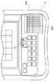
図1はスロットマシン1の正面図である。スロットマシン1は、キャビネット2の開口部に扉体3が開閉自在に設けられている。また、キャビネット2の上部にトップフレーム4が取り付けられている。トップフレーム4の正面には化粧パネル板41が施されている。
【0029】
遊技情報を表示する表示装置21はキャビネット2内に設置される。表示装置21の表示を視認可能とするために、扉体3の上部には窓が形成され、表示装置21の表示を視認可能とするため、あるいは表示装置21を保護するための透明板が前記窓に取り付けられている。そして、前記窓の両翼には、遊技状態に応じて発生される効果音あるいは効果音楽を聴覚容易とするための透過孔902(902L及び902R)が形成されている。
【0030】
扉体3の正面中央部には突出する形で操作部5が配置されている。操作部5の右側の傾斜面には、各種操作ボタンが配列されると共にコインを投入するコイン投入口51が備えられている。操作部5の右側には、キャビネット2内に収納される紙幣識別機(ビルバリデータ)に紙幣を案内するための紙幣案内部52が備えられている。
【0031】
操作部5の下部には、扉体3と開閉自在に連結する枠体6が設けられている。枠体6には化粧パネル板61が内包されている。枠体6の下部であって、扉体3の底部にはコインを収容するコイン受け皿30が形成されている。
【0032】
図2は操作部5の部分拡大図である。前述の紙幣案内部52は紙幣案内板52Aと取着体52Bで構成される。紙幣案内板52Aと取着体52Bは一体となって、キャビネット2に取り付けられている。
【0033】
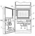
図3は扉体3を開いた状態図である。図3に示されるように、キャビネット2内には紙幣識別機22と紙幣収容部23が設置されている。紙幣識別機22は、紙幣案内部52から投入された紙幣の真偽あるいは良否を判定する。紙幣収容部(スタッカ)23は、紙幣識別機22で有効とされた紙幣を収容する。紙幣案内部52の紙幣挿入口520(図5参照)で案内された紙幣は、紙幣識別機22の紙幣取入口に取り入れられる。
【0034】
また、図3において、扉体3の裏面側には、回収容器となるドレンボトル7が取着体52Bの直下に装着されている。
【0035】
図4は紙幣案内板52Aの斜視図である。図4に示されるように、紙幣案内板52Aは複数の略直線状の溝521が列状に形成されている。紙幣案内板52Aには、紙幣案内面522に対して上面が僅かに沈んだ形で、溝521を複数の領域に仕切るための仕切部材523が形成されている。そして、図4に示されるように、仕切部材523により仕切られた溝521の各開口溝524の長さは、遊技機で使用されるコイン10の直径よりも小さく形成されている。
【0036】
図5は、紙幣案内板52Aと取着体52Bが組み合わされた状態での縦断面図である。図5に示されるように、紙幣案内板52Aは、紙幣挿入空間となる紙幣挿入口520に着脱自在に取着される。また、紙幣が容易に取り入れられる様にするため、紙幣案内板52Aは、紙幣挿入口520の下辺部よりキャビネット2の前面方向に向けて突出している。
【0037】
紙幣挿入口520を形成する周壁は下方に連続し、紙幣挿入口520と対向する第1の開口空間となる第1の開口部525を形成する。第1の開口部525を形成する周壁は更に下方に連続し、下方に向けて開放された第2の開口部526を形成する。紙幣挿入口520と第1の開口部525と第2の開口部526は、下側が頂点となる概ね四角錐体の空間を形成する。そして、紙幣案内板52Aは、第1の開口部525を覆うように形成されている。なお、第1の開口部525と第2の開口部526は、開口溝524を介して外部から入った異物を導くためのものである。
【0038】
図6は、紙幣案内部52の斜視分解組立図である。図6において、紙幣案内板52Aの後壁には突起528Aが形成されている。紙幣案内板52Aの前方下壁には円柱状突起528Bが形成されている。円柱状突起528Bに雌ねじが形成されている。一方、取着体52Bの第1の開口部525の後方内壁には係止溝528Cが形成されている。紙幣案内板52Aの突起528Aを取着体52Bの係止溝528Cに挿入し、紙幣案内板52Aを第1の方向に回転すれば、紙幣案内板52Aは取着体52Bに組み立てられる。取着体52Bの係止溝528Cに突起528Aを挿入した状態で、第1の方向と反対の第2の方向に回転すれば、紙幣案内板52Aを取着体52Bから分離可能になる。
【0039】
紙幣案内板52Aの円柱状突起528Bと取着体52Bを固定ねじBFで固定し、紙幣案内板52Aと取着体52Bを一体にする。そして、一体になった紙幣案内板52Aと取着体52Bを、操作部5のコントロールパネル50の切り欠き部に挿入する。次に、コントロールパネル50に設けられた取り付けブラケット501に、一体になった紙幣案内板52Aと取着体52Bを固定ねじBFで固定し、組立完了状態となる。
【0040】
より具体的には、図5に示されるように、取着体52Bの前部に形成された溝527をコントロールパネル50の縁に挿入し、取着体52Bをコントロールパネル50側に倒す。取着体52Bの鍔がコントロールパネル50の上面に当接し、固定ねじBFで固定すれば、固定状態となる。
【0041】
図7は、扉体3を裏面側から見た部分図である。図7に示されるように、ドレンボトル7は扉体3の裏面側に設置される。そして、ドレンボトル7の上面開口部70は、取着体52Bにおける第2の開口部526の真下に位置している。つまり、ドレンボトルの上面開口部70の重心と第2の開口部526の重心が、概ね一致するようにドレンボトル7は設置される。また、ドレンボトル7の上面開口部70の断面積は、第2の開口部526の下端部における断面よりも大きくなっている。
【0042】
図8は、枠体6の斜視分解組立図である。図8において、枠板632は、概ねコの字状に形成され、化粧パネル板61が収容される。また、枠板632には、カバー62が取り付けられる。枠板632の左翼には、枠体6を扉体3に施錠あるいは解錠するためのシリンダ錠6Aが設けられている。枠板632の右翼には、貫通穴633が形成される。貫通穴633に支軸64が挿入され、枠体6は扉体3と回転結合する。したがって、化粧パネル板61とカバー62と枠板632は一体となって開閉する。
【0043】
カバー62の背面には、引掛り金具71が二つ取り付けられている。一方、ドレンボトル7の左右側面には、円柱状のピン7Aが突出している。引掛り金具71のU字状溝にピン7Aが係止して、ドレンボトル7がカバー62の背面に設置される状態となる。また、ドレンボトル7を持ち上げれば、引掛り金具71とピン7Aの係止状態が解消し、ドレンボトル7を別の場所に移動できる。なお、ドレンボトル7が枠体6に設置される状態においては、ドレンボトル7の底面は、枠体6の底面より若干上に位置する。
【0044】
図8に示されるように、ドレンボトル7は上面開口部70の下部に位置する収容部分の水平断面が横方向の大きな長さ形状を有する横長薄型の形状となっている。そして、前記横方向のドレンボトル7は、カバー62の裏面に沿うように装着されている。
【0045】
ドレンボトル7は略透明状あるいは半透明状の材質よりなる物質(例えば、ガラスあるいは合成樹脂)で形成されている。そして、ドレンボトル7の液体収容能力は約1リットルである。
【0046】
次に、作用を説明する。図4において説明されたように、紙幣案内板52Aは複数の開口溝524が列状に形成されている。したがって、紙幣案内板52A上に飲料等の異物がこぼれた場合であっても、開口溝524を通じて異物がキャビネット2内部の各種装置にかかることなく回収することが可能となり、当該各種装置の破損を防止することが可能となる。
【0047】
また、図5に示されるように、紙幣案内板52Aは底面が開口した袋状になっており、内周壁は溶液あるいは投入された異物が底面に自重落下しやすい傾斜面を形成している。同様に、取着体52Bにおける第1の開口部525と第1の開口部525に連続する第2の開口部526も底面が開口した袋状になっており、内周壁は水溶液あるいは投入された異物が底面に自重落下しやすい傾斜面を形成している。
【0048】
すなわち、開口溝524の略真下方向に位置する第1の開口部525と第2の開口部526は、外部からの溶液などを含む異物を誘導する誘導部を形成している。そして、図7に示されるように、取着体52Bの第2の開口部526の真下にドレンボトル7を備えることにより、前記誘導部に誘導される異物をドレンボトル7に回収できる。
【0049】
このようにして、紙幣案内板52Aの開口溝524から入る外部からの異物を、前記誘導部を経てドレンボトル7に回収することが可能となる。そして、キャビネット2内の各装置が外部からの異物により故障するといった不具合を低減し得、特に、異物が水分である場合には、この作用は顕著となる。
【0050】
次に、図7における作用を説明する。「ドレンボトル7の上面開口部70の断面積は、第2の開口部526の下端部における断面よりも大きくなっている」ことは既に説明された。前記のように構成することにより、図5における取着体52Bから誘導される外部からの異物をドレンボトル7の外に漏れることを防止し得、ドレンボトル7へと回収しやすくすることが可能となる。
【0051】
また、図8では、「カバー62の引掛り金具71とドレンボトル7のピン7Aが係止あるいは係止状態を解消できる」ことを説明した。すなわち、ドレンボトル7が扉体3の裏面に一体的に形成されておらず、取り外し自在に装着されている。外部からの異物がドレンボトル7に溜まった際であっても比較的容易にドレンボトル7を取り外すことが可能となり、外部からの異物をドレンボトル7から捨てることが可能となる。また、ドレンボトル7は扉体3の裏面に装着されているので、扉体3を開放するのみで、他の装置の存在に影響されることなくドレンボトル7の取り外しが可能となるのである。
【0052】
また、図8の説明においては、「ドレンボトル7は上面開口部70の下部に位置する収容部分の水平断面が横方向の大きな長さ形状を有する横長の形状となっている。そして、前記横方向のドレンボトル7は、カバー62の裏面に沿うように装着されている」ことが述べられた。
【0053】
図3で説明されたように、キャビネット2内には紙幣識別機22と紙幣収容部23が設置されている。また、キャビネット2内部にはコインガイド24が配置されている。コインガイド24の背後にはスロットマシン1を制御するためのプリント基板あるいはシェルフ25が実装されている。更に、コインガイド24の下部には、図示されないホッパーが配置されている。このように、キャビネット2内部は過密実装状態であり、ドレンボトル7がキャビネット2内部に向けて突出するスペースは存在しない。
【0054】
また、図7に示されるように、コイン投入口51から投入されたコイン10をコインガイド24あるいはコイン受け皿30に振り分けるコイン振り分け装置が、扉体3の背面であって、取着体52Bに隣接している。
【0055】
以上のように限られたスペースの中から、ドレンボトル7の収容能力を大きくするために、ドレンボトル7は横長薄型の形状に至った。つまり、ドレンボトル7はキャビネット2内における省スペース性に優れ、前記の制約条件において比較的多くの異物を収容部分(ドレンボトル7内)に回収することができるようになった。
【0056】
また、また、図8の説明においては、「ドレンボトル7は略透明状あるいは半透明状の材質よりなる物質(例えば、ガラスあるいは合成樹脂)で形成されている」ことを述べた。扉体3あるいは枠体6を開くと、扉体3あるいは枠体6と共にドレンボトル7も移動し、ドレンボトル7を視認可能となる。その際に、ドレンボトル7は略透明状あるいは半透明状の材質よりなる物質で形成すれば、ドレンボトル7内に回収された外部からの異物の回収量を視認し易くなる。そして、外部からの異物を捨てるタイミングを、その都度ドレンボトル7内を取り外して確認することなく回収量を認識し得る。
【0057】
【発明の効果】
本発明によれば、紙幣を前記紙幣挿入口に案内するための紙幣案内板を備えた遊技機において「前記紙幣案内板には、開口溝と、前記開口溝の略真下方向に位置し外部からの異物を誘導する誘導部と、が備えられており、前記扉体の裏面側には、前記誘導部に誘導される異物を回収するための回収容器が備えられている」ように構成することにより、当該紙幣案内板の開口溝から入る外部からの異物を、当該誘導部を経て回収容器に回収することが可能となり、筐体内の各装置が外部からの異物により故障するといった不具合を低減し得、特に、異物が水分である場合には、この作用が顕著となる。
【0058】
また、本発明によれば、前述の遊技機において、「前記回収容器の上面開口部は、前記誘導部の下の略真下方向に位置するとともに、当該誘導部の下端部における断面よりも大きな断面積を有する」ように構成することにより、当該誘導部から誘導される外部からの異物を回収容器の外に漏れることを防止し得、該回収容器へと回収しやすくすることが可能となる。
【0059】
更に、本発明によれば、前述の遊技機において、「前記回収容器は、前記扉体の裏面側に取り付けられており、且つ該扉体の裏面より取り外し自在に装着されている」ように構成することにより、当該回収容器が扉体の裏面に一体的に形成されておらず、取り外し自在に装着されているので、外部からの異物が回収容器に溜まった際であっても比較的容易に取り外すことが可能となり、外部からの異物を回収容器から捨てることが可能となる。
【0060】
また、本発明によれば、前述のいずれかの遊技機において、「前記回収容器は、その上面開口部の下部に位置する収容部分の水平断面が横方向の大きな長さ形状を有する横長の形状であるとともに、前記横方向が前記扉体の裏面に沿うように装着されている」ように構成することにより、当該回収容器の形状を非常に薄型としやすく、そのため筐体内における省スペース性に優れ、この条件において比較的多くの異物を収容部分に回収することができる。
【0061】
更に、本発明によれば、前述の遊技機において「前記回収容器は、略透明状或いは半透明状の材質よりなる」ように構成することにより、当該回収容器内に回収された外部からの異物の回収量を視認し易いので、該外部からの異物を捨てるタイミングをその都度取り外して確認することなく認識し得る。
【図面の簡単な説明】
【図1】本発明におけるスロットマシンの正面図である。
【図2】本発明における操作部の部分拡大図である。
【図3】本発明における扉体を開いた状態図である。
【図4】本発明における紙幣案内板の斜視図である。
【図5】本発明における紙幣案内板と取着体が組み合わされた状態での縦断面図である
【図6】本発明における紙幣案内部の斜視分解組立図である。
【図7】本発明における扉体を裏面側から見た部分図である。
【図8】本発明における枠体の斜視分解組立図である。
【符号の説明】
1 スロットマシン
2 キャビネット
3 扉体
4 トップフレーム
5 操作部
6 枠体
7 ドレンボトル
7A ピン
10 コイン
21 表示装置
22 紙幣識別機
52 紙幣案内部
52A 紙幣案内板
52B 取着体
70 上面開口部
71 引掛り金具
520 紙幣挿入口
521 溝
522 紙幣案内面
523 仕切部材
524 開口溝
525 第1の開口部
526 第2の開口部[0001]
TECHNICAL FIELD OF THE INVENTION
The present invention relates to a gaming machine.
[0002]
[Prior art]
Some gaming machines such as video poker and slot machines installed in casinos and the like have a bill insertion slot for directly inserting bills instead of coins and medals (for example, Patent Document 1) ).
[0003]
With such a gaming machine, when a player runs out of coins or the like on hand, he / she must go to the money changing machine from the seat or call a clerk at the amusement arcade in order to exchange money from bills to coins. Without it, the game can be continued.
[0004]
In many cases, a bill guide plate for guiding a bill to the bill insertion slot is provided at a lower side portion of such a bill insertion slot. By providing the bill guide plate in this way, a player can easily insert a bill into the bill insertion slot.
[0005]
[Patent Document 1]
JP-A-9-106471
[Problems to be solved by the invention]
However, there are some people who play games while having a simple meal or drink in a game arcade, and spills may occur on the bill guide plate by some kind of momentum. In addition, there are some people who are frustrated that the game result is not as desired and throw the beverage they have at the gaming machine.
[0007]
In such a case, since the bill guide plate has a relatively large area facing upward, the bill guide plate has a structure that is more susceptible to foreign substances such as spilled beverages than other parts. Further, since the bill guide plate is provided in contact with the bill insertion slot, there is a possibility that the above-described foreign matter may enter the bill insertion slot.
[0008]
Since the intrusion of foreign matter into the bill insertion slot leads to a failure of the gaming machine, it is necessary to prevent such a situation in advance.
[0009]
To solve such problems, a gaming machine provided with a drainage port on a bill guide plate has been considered. However, the gaming machine is apt to be clogged because the drainage port is small. Was simply pouring into the empty space below the enclosure. Therefore, when a large amount of water is spilled, drainage is not sufficient, and as a result, the inside of the housing is contaminated.
[0010]
The present invention has been made in view of the above problems, and a purpose of the present invention is to collect foreign objects without spilling on various devices in the housing, even when foreign objects have spilled on the bill guide plate. It is to provide a gaming machine capable of doing so.
[0011]
[Means for Solving the Problems]
The present invention provides a gaming machine capable of collecting foreign matter such as liquid spilled on a bill guide plate through an opening groove provided in the bill guide plate.
[0012]
More specifically, the present invention provides the following.
[0013]
(1) A housing, a door body provided at a front opening of the housing, a bill insertion slot provided at the door body, and a projecting front side of the housing from a lower side of the bill insertion slot. And a bill guide plate for guiding a bill to the bill insertion slot, wherein the bill guide plate has an opening groove and an external groove located substantially directly below the opening groove. And a guide section for guiding foreign matter, and a collecting container for collecting foreign matter guided by the guide section is provided on the back side of the door body. .
[0014]
According to the invention of the above (1), in a gaming machine provided with a bill guide plate for guiding a bill to a bill insertion slot, “the bill guide plate has an opening groove and a position substantially directly below the opening groove. And a guide portion for guiding foreign matter from the outside, and a collection container for collecting foreign material guided by the guide portion is provided on the back side of the door body. With this configuration, foreign matter entering from the opening groove of the bill guide plate from the outside can be collected in the collection container through the guiding portion, and each device in the housing is broken down by the foreign matter from the outside. This effect is particularly remarkable when the foreign matter is water.
[0015]
In a conventional gaming machine, if foreign matter such as liquid spills on the bill guide plate, it flows into the bill insertion slot, which causes various internal devices to break down. was there.
[0016]
Then, after providing an opening groove in the bill guide plate of the gaming machine as in the present invention, by providing the gaming machine with a collection container for collecting foreign matter flowing from the opening groove, the foreign matter is inserted into the bill insertion slot. It is possible to prevent problems caused by the inflow and accumulation in the housing in advance.
[0017]
(2) The upper surface opening of the recovery container is located substantially directly below the guide portion and has a larger cross-sectional area than a cross section at a lower end portion of the guide portion. Gaming machine.
[0018]
According to the invention of (2) described above, in the gaming machine of (1), "the upper surface opening of the collection container is located substantially directly below the guide portion and a cross section at the lower end portion of the guide portion. Having a larger cross-sectional area ", it is possible to prevent external foreign substances guided from the guide portion from leaking out of the collection container, and to facilitate collection in the collection container. It becomes possible.
[0019]
(3) The gaming machine according to (1) or (2), wherein the collection container is attached to a back surface side of the door body and is detachably attached to the back surface of the door body. .
[0020]
According to the invention of (3) described above, in the gaming machine of (1) or (2), "the collection container is attached to the back side of the door body and is detachable from the back side of the door body. By being configured as `` attached '', the collection container is not integrally formed on the back surface of the door body and is detachably mounted, so that when foreign matter from the outside collects in the collection container Even in this case, it is possible to relatively easily remove the foreign matter, and it is possible to discard foreign matter from the outside from the collection container.
[0021]
Further, since the collection container is attached to the back surface of the door, the collection container can be removed without being affected by the presence of other devices only by opening the door.
[0022]
(4) The collection container has a horizontally long cross-section having a large length in a horizontal direction, and a horizontal section of a storage portion located below the upper opening portion, and the horizontal direction extends along the back surface of the door body. The gaming machine according to any one of (1) to (3), wherein the gaming machine is mounted as described above.
[0023]
According to the invention described in (4) above, in the gaming machine according to any one of (1) to (3), "the collection container has a large horizontal cross-section of a storage portion located at a lower portion of an upper surface opening thereof. The collection container is very thin, and the shape of the collection container is very thin. It is excellent in space saving in the body, and under this condition, a relatively large number of foreign substances can be collected in the accommodation portion.
[0024]
(5) The gaming machine according to any one of (1) to (4), wherein the collection container is made of a substantially transparent or translucent material.
[0025]
According to the invention of (5) described above, in the gaming machine of (1) to (4), the recovery container is constituted by “the recovery container is made of a substantially transparent or translucent material”. Since it is easy to visually recognize the amount of foreign matter collected inside, it is possible to recognize the timing of discarding foreign matter without removing and confirming each time.
[0026]
BEST MODE FOR CARRYING OUT THE INVENTION
Hereinafter, embodiments of the present invention will be described with reference to the drawings. In this embodiment, the present invention will be described by applying the present invention to a slot machine. However, the present invention is not limited to this, and may be applied to various types of gaming machines such as video game machines, coin game machines, and card game machines. Can be.
[0027]
Next, the configuration of the slot machine will be described.
[0028]
FIG. 1 is a front view of the
[0029]
A
[0030]
An operation unit 5 is disposed at the center of the front of the
[0031]
A
[0032]
FIG. 2 is a partially enlarged view of the operation unit 5. The above-mentioned bill guide
[0033]
FIG. 3 is a state diagram in which the
[0034]
In addition, in FIG. 3, a
[0035]
FIG. 4 is a perspective view of the
[0036]
FIG. 5 is a longitudinal sectional view in a state where the
[0037]
The peripheral wall that forms the
[0038]
FIG. 6 is an exploded perspective view of the
[0039]
The
[0040]
More specifically, as shown in FIG. 5, the
[0041]
FIG. 7 is a partial view of the
[0042]
FIG. 8 is an exploded perspective view of the
[0043]
Two hooks 71 are attached to the back of the
[0044]
As shown in FIG. 8, the
[0045]
The
[0046]
Next, the operation will be described. As described in FIG. 4, the
[0047]
As shown in FIG. 5, the
[0048]
In other words, the
[0049]
In this manner, foreign matter entering from the
[0050]
Next, the operation in FIG. 7 will be described. "The cross-sectional area of the
[0051]
In FIG. 8, it has been described that "the
[0052]
In addition, in the description of FIG. 8, “the
[0053]
As described in FIG. 3, the
[0054]
As shown in FIG. 7, a coin sorting device for sorting the
[0055]
From the limited space as described above, in order to increase the capacity of storing the
[0056]
In addition, in the description of FIG. 8, it has been described that “the
[0057]
【The invention's effect】
According to the present invention, in a gaming machine provided with a bill guide plate for guiding a bill to the bill insertion slot, `` the bill guide plate has an opening groove, and is located almost directly below the opening groove from the outside. And a guide portion for guiding foreign matter, and a collection container for collecting the foreign material guided by the guide portion is provided on the back surface side of the door body. Accordingly, foreign matter entering from the opening groove of the bill guide plate from the outside can be collected in the collection container through the guiding portion, and the problem that each device in the housing is broken down by the foreign matter is reduced. Particularly, when the foreign matter is water, this effect becomes remarkable.
[0058]
Further, according to the present invention, in the above-mentioned gaming machine, in the above-described gaming machine, "the upper surface opening of the collection container is positioned substantially directly below the guide portion, and has a larger cross-section than the cross section at the lower end portion of the guide portion. By having a configuration having “area”, it is possible to prevent foreign substances guided from the guiding portion from leaking out of the collection container, and to facilitate collection in the collection container.
[0059]
Further, according to the present invention, in the above-mentioned gaming machine, the constitution is such that "the collection container is attached to the back side of the door body and is detachably attached from the back side of the door body". By doing so, the collection container is not integrally formed on the back surface of the door body and is detachably mounted, so that even when foreign matter from the outside collects in the collection container, it is relatively easy. It becomes possible to remove, and it becomes possible to throw away foreign substances from the collection container.
[0060]
Further, according to the present invention, in any one of the above-described gaming machines, it is preferable that the collection container has a horizontally long shape in which a horizontal cross section of a housing portion located at a lower portion of an upper surface opening has a large length in a horizontal direction. And the lateral direction is attached so as to be along the back surface of the door body ", whereby the shape of the collection container is easily made very thin, so that the space saving in the housing is excellent. Under this condition, a relatively large amount of foreign matter can be collected in the accommodation portion.
[0061]
Further, according to the present invention, by configuring the above-mentioned gaming machine such that the collection container is made of a substantially transparent or translucent material, foreign matter collected in the collection container from the outside It is easy to visually recognize the collected amount, so that it is possible to recognize the timing of discarding foreign matter from the outside without removing and confirming the timing each time.
[Brief description of the drawings]
FIG. 1 is a front view of a slot machine according to the present invention.
FIG. 2 is a partially enlarged view of an operation unit according to the present invention.
FIG. 3 is a view showing a state where a door body in the present invention is opened.
FIG. 4 is a perspective view of a bill guide plate according to the present invention.
FIG. 5 is a longitudinal sectional view showing a state in which a bill guide plate and an attaching body according to the present invention are combined. FIG. 6 is an exploded perspective view of a bill guide unit according to the present invention.
FIG. 7 is a partial view of the door according to the present invention as viewed from the back side.
FIG. 8 is an exploded perspective view of the frame according to the present invention.
[Explanation of symbols]
DESCRIPTION OF
Claims (5)
前記筐体の前面開口部に設けられた扉体と、
前記扉体に設けられた紙幣挿入口と、
前記紙幣挿入口の下辺部より筐体前面方向に向けて突出した、紙幣を前記紙幣挿入口に案内するための紙幣案内板と、を備える遊技機であって、
前記紙幣案内板には、開口溝と、前記開口溝の略真下方向に位置し外部からの異物を誘導する誘導部と、が備えられており、
前記扉体の裏面側には、前記誘導部に誘導される異物を回収するための回収容器が備えられていることを特徴とする遊技機。A housing;
A door provided at the front opening of the housing,
A bill insertion slot provided in the door body,
A gaming machine comprising: a bill guide plate for projecting a bill to the bill insertion slot, protruding toward a front side of the housing from a lower side of the bill insertion slot,
The bill guide plate includes an opening groove, and a guiding portion that is located substantially directly below the opening groove and guides foreign matter from outside,
A gaming machine, characterized in that a collecting container for collecting foreign substances guided by the guiding section is provided on a back side of the door body.
Priority Applications (8)
| Application Number | Priority Date | Filing Date | Title |
|---|---|---|---|
| JP2002316730A JP2004147880A (en) | 2002-10-30 | 2002-10-30 | Game machine |
| AT03025018T ATE404962T1 (en) | 2002-10-30 | 2003-10-30 | SLOT MACHINE WITH BILL ACCEPTANCE DEVICE |
| US10/696,584 US20040224776A1 (en) | 2002-10-30 | 2003-10-30 | Gaming machine |
| ES03025018T ES2309264T3 (en) | 2002-10-30 | 2003-10-30 | GAME MACHINE PROVIDED WITH A SLOT FOR THE INTRODUCTION OF TICKETS. |
| EP03025018A EP1416453B1 (en) | 2002-10-30 | 2003-10-30 | Gaming machine with bill insertion slot |
| DE60322815T DE60322815D1 (en) | 2002-10-30 | 2003-10-30 | Slot machine with bill acceptor |
| AU2003259573A AU2003259573A1 (en) | 2002-10-30 | 2003-10-30 | Gaming machine |
| ZA200308471A ZA200308471B (en) | 2002-10-30 | 2003-10-30 | Gaming Machine. |
Applications Claiming Priority (1)
| Application Number | Priority Date | Filing Date | Title |
|---|---|---|---|
| JP2002316730A JP2004147880A (en) | 2002-10-30 | 2002-10-30 | Game machine |
Publications (1)
| Publication Number | Publication Date |
|---|---|
| JP2004147880A true JP2004147880A (en) | 2004-05-27 |
Family
ID=32089552
Family Applications (1)
| Application Number | Title | Priority Date | Filing Date |
|---|---|---|---|
| JP2002316730A Pending JP2004147880A (en) | 2002-10-30 | 2002-10-30 | Game machine |
Country Status (8)
| Country | Link |
|---|---|
| US (1) | US20040224776A1 (en) |
| EP (1) | EP1416453B1 (en) |
| JP (1) | JP2004147880A (en) |
| AT (1) | ATE404962T1 (en) |
| AU (1) | AU2003259573A1 (en) |
| DE (1) | DE60322815D1 (en) |
| ES (1) | ES2309264T3 (en) |
| ZA (1) | ZA200308471B (en) |
Cited By (2)
| Publication number | Priority date | Publication date | Assignee | Title |
|---|---|---|---|---|
| JP2005334535A (en) * | 2004-05-31 | 2005-12-08 | Heiwa Corp | Token throwing-in device |
| JP2006065435A (en) * | 2004-08-25 | 2006-03-09 | Oki Electric Ind Co Ltd | Medium processor |
Families Citing this family (21)
| Publication number | Priority date | Publication date | Assignee | Title |
|---|---|---|---|---|
| US7806770B2 (en) * | 2006-04-10 | 2010-10-05 | Bally Gaming, Inc. | Gaming machine having a mounting assembly for a flat panel display |
| JP2008307335A (en) * | 2007-06-18 | 2008-12-25 | Aruze Corp | Game machine |
| JP2009165804A (en) * | 2008-01-11 | 2009-07-30 | Aruze Corp | Gaming machine |
| US8764573B2 (en) * | 2008-10-08 | 2014-07-01 | Konami Gaming, Inc. | Gaming machine cabinet |
| US8641535B2 (en) * | 2009-12-03 | 2014-02-04 | Patent Rights Protection Group, Llc | Gaming machine cabinet construction and method |
| US8430756B2 (en) | 2010-05-11 | 2013-04-30 | Patent Rights Protection Group, Llc | Gaming machine cabinet with edge lighting |
| AU2011288961B2 (en) * | 2010-08-09 | 2014-09-25 | Ainsworth Game Technology Limited | Gaming machine |
| USD820915S1 (en) | 2015-09-22 | 2018-06-19 | Ags Llc | Gaming machine |
| USD813954S1 (en) | 2015-09-24 | 2018-03-27 | Ags Llc | Game tower |
| USD818048S1 (en) | 2015-10-05 | 2018-05-15 | Ags Llc | Gaming machine |
| US9997010B2 (en) | 2015-12-18 | 2018-06-12 | Ags Llc | Electronic gaming device with external lighting functionality |
| US10002488B2 (en) | 2015-12-17 | 2018-06-19 | Ags Llc | Electronic gaming device with call tower functionality |
| USD843473S1 (en) | 2017-04-07 | 2019-03-19 | Ags Llc | Gaming machine |
| USD865873S1 (en) | 2017-08-23 | 2019-11-05 | Ags Llc | Gaming machine |
| USD852890S1 (en) | 2017-11-30 | 2019-07-02 | Ags Llc | Gaming machine |
| USD888837S1 (en) | 2018-02-02 | 2020-06-30 | Ags Llc | Support structure for gaming machine display |
| USD939632S1 (en) | 2018-07-17 | 2021-12-28 | Ags Llc | Gaming machine |
| USD969926S1 (en) | 2019-04-24 | 2022-11-15 | Ags Llc | Gaming machine |
| USD978810S1 (en) | 2019-07-31 | 2023-02-21 | Ags Llc | LED matrix display |
| USD969927S1 (en) | 2019-08-02 | 2022-11-15 | Ags Llc | Gaming machine |
| US11380157B2 (en) | 2019-08-02 | 2022-07-05 | Ags Llc | Servicing and mounting features for gaming machine display screens and toppers |
Family Cites Families (7)
| Publication number | Priority date | Publication date | Assignee | Title |
|---|---|---|---|---|
| US4230213A (en) * | 1978-12-26 | 1980-10-28 | La Crosse Cooler Company, Inc. | Liquid rejecting coin chute |
| US4269297A (en) * | 1979-11-13 | 1981-05-26 | Aosco & Associates, Ltd. | Vending machine see-thru coin box |
| US5156250A (en) * | 1991-09-26 | 1992-10-20 | Mid-South Enterprises | Liquid diverter for currency receiver |
| US5318164A (en) * | 1992-05-15 | 1994-06-07 | Mars Incorporated | Vending machine apparatus and method to prevent fraud and minimize damage from injected fluids |
| US5566809A (en) * | 1992-06-02 | 1996-10-22 | Coin Acceptors, Inc. | Vending machine protective device |
| KR970005397B1 (en) * | 1992-07-29 | 1997-04-16 | 가부시끼가이샤 닛뽄곤락스 | Paper money identifying device |
| KR970007741B1 (en) * | 1993-03-31 | 1997-05-16 | 가부시끼가이샤 니뽄곤락스 | Bill processor |
-
2002
- 2002-10-30 JP JP2002316730A patent/JP2004147880A/en active Pending
-
2003
- 2003-10-30 AT AT03025018T patent/ATE404962T1/en active
- 2003-10-30 ES ES03025018T patent/ES2309264T3/en not_active Expired - Lifetime
- 2003-10-30 AU AU2003259573A patent/AU2003259573A1/en not_active Abandoned
- 2003-10-30 ZA ZA200308471A patent/ZA200308471B/en unknown
- 2003-10-30 DE DE60322815T patent/DE60322815D1/en not_active Expired - Lifetime
- 2003-10-30 US US10/696,584 patent/US20040224776A1/en not_active Abandoned
- 2003-10-30 EP EP03025018A patent/EP1416453B1/en not_active Expired - Lifetime
Cited By (4)
| Publication number | Priority date | Publication date | Assignee | Title |
|---|---|---|---|---|
| JP2005334535A (en) * | 2004-05-31 | 2005-12-08 | Heiwa Corp | Token throwing-in device |
| JP4518841B2 (en) * | 2004-05-31 | 2010-08-04 | 株式会社平和 | Medals insertion device |
| JP2006065435A (en) * | 2004-08-25 | 2006-03-09 | Oki Electric Ind Co Ltd | Medium processor |
| JP4544940B2 (en) * | 2004-08-25 | 2010-09-15 | 沖電気工業株式会社 | Media processing device |
Also Published As
| Publication number | Publication date |
|---|---|
| ZA200308471B (en) | 2004-04-19 |
| EP1416453A3 (en) | 2006-03-29 |
| DE60322815D1 (en) | 2008-09-25 |
| EP1416453A2 (en) | 2004-05-06 |
| US20040224776A1 (en) | 2004-11-11 |
| AU2003259573A1 (en) | 2004-05-20 |
| EP1416453B1 (en) | 2008-08-13 |
| ATE404962T1 (en) | 2008-08-15 |
| ES2309264T3 (en) | 2008-12-16 |
Similar Documents
| Publication | Publication Date | Title |
|---|---|---|
| JP2004147880A (en) | Game machine | |
| USRE46473E1 (en) | Slot-type gaming machine with improved cabinet | |
| EP2012282A2 (en) | Gaming machine | |
| JP4833312B2 (en) | Game machine | |
| AU2007201229A1 (en) | Video slot machine allowing extra bets | |
| CN1606041A (en) | Gaming machine and game medium receiving unit mountable on gaming machine | |
| JP2004147879A (en) | Game machine | |
| JP4693000B2 (en) | Amusement media receiving box and gaming machine | |
| US6852022B2 (en) | Coin collection system for a gaming machine | |
| JPH1024155A (en) | Pinball game machine | |
| JP2007215654A (en) | Game machine | |
| JP2009082620A (en) | Game machine | |
| US8672766B1 (en) | Rol-lee gaming cabinet | |
| JP4230092B2 (en) | Yugi Island | |
| JP2002000871A (en) | Game machine | |
| AU2003259572A8 (en) | Gaming machine | |
| US20040171426A1 (en) | Gaming machine | |
| JP2003159364A (en) | Slot machine | |
| US20040092316A1 (en) | Gaming machine with game medium straddling device | |
| JP4313287B2 (en) | Game machine | |
| KR200287095Y1 (en) | Apparatus For Paying Prizes of a gambling machine | |
| JP2001006046A (en) | Automatic vending machine with raw material pack take- out device | |
| JP2012020198A (en) | Gaming machine | |
| JP4131547B2 (en) | Slot machine | |
| JP2011251176A (en) | Game machine |
Legal Events
| Date | Code | Title | Description |
|---|---|---|---|
| A621 | Written request for application examination |
Free format text: JAPANESE INTERMEDIATE CODE: A621 Effective date: 20050810 |
|
| A131 | Notification of reasons for refusal |
Free format text: JAPANESE INTERMEDIATE CODE: A131 Effective date: 20080805 |
|
| A02 | Decision of refusal |
Free format text: JAPANESE INTERMEDIATE CODE: A02 Effective date: 20081202 |