JP4230092B2 - Yugi Island - Google Patents
Yugi Island Download PDFInfo
- Publication number
- JP4230092B2 JP4230092B2 JP2000144818A JP2000144818A JP4230092B2 JP 4230092 B2 JP4230092 B2 JP 4230092B2 JP 2000144818 A JP2000144818 A JP 2000144818A JP 2000144818 A JP2000144818 A JP 2000144818A JP 4230092 B2 JP4230092 B2 JP 4230092B2
- Authority
- JP
- Japan
- Prior art keywords
- coin
- island
- insertion portion
- coins
- unit
- Prior art date
- Legal status (The legal status is an assumption and is not a legal conclusion. Google has not performed a legal analysis and makes no representation as to the accuracy of the status listed.)
- Expired - Fee Related
Links
Images


Description
【0001】
【発明の属する技術分野】
本発明は、コイン(コイン状の遊技価値媒体)を使用する遊技機(例えば、スロットマシンなど)が複数並んで設置される遊技島に関する。
【0002】
【従来の技術】
例えば、スロットマシンは、周知のように、遊技者が遊技用のコインを投入することを条件に遊技を開始し、スクロールしていた複数列の図柄が所定の態様(例えば、「777」)で停止すると、内部に設けられたコイン排出装置が作動して、賞特典としての所定量のコインの排出(即ち、コインの賞出)を実行するものである。このようなスロットマシンなどのコインを使用した遊技機は、パチンコ機に比較してファッション性が高いので特に若い人たちに歓迎されている。
【0003】
ところで、遊技店におけるこの種の遊技機は、パチンコ機と同様に、遊技島又は遊技機設置島(以下場合により、単に島という。)と呼ばれる設備の両面又は片面に複数並べて設けられる。そして従来、この遊技島は、例えば図9(c)に符号1で示すように、スロットマシン等の遊技機2が十数台或いはそれ以上取り付けられる横長のもので、島のほぼ全長に亘ってコインの循環流路が連続する共通のコイン循環装置が一組設けられ、この一組のコイン循環装置によって、島内の各遊技機からオバーフローしたコインを回収するとともに、賞出用のコインを各遊技機のコイン排出装置に補給できるように構成されていた。即ち、従来のスロットマシン等の遊技機の島は、一直線に横たわる長大な一体型の設備であった。
【0004】
しかも、コインの賞出によって、島内に保有されるコインの全量が減ったときに、島全体に対して(即ち、前記コイン循環装置に対して)コインを適宜補給するためのコイン投入部は、従来、このような長大な島の端側のみに設けられていた。また、装飾と防犯のために島の表面(遊技機取付部の周囲等)を覆う各種表面板部材(パネル類)は、例えばネジ部材などの固定手段によって島の骨組み(フレーム)に対して個々に固定されており、島内機器(例えば、コイン循環装置を構成する機器)のメンテナンス作業の際には、対応する表面板部材の固定手段を取り外して、その表面板部材の固定状態を個々に解除しなければならなかった。
【0005】
【発明が解決しようとする課題】
このため、上述したスロットマシン等の従来の遊技島にあっては、以下のような問題点があった。
即ち、従来では、表面板部材の固定がネジ部材などの固定手段によって全て個々に実現される構成であるため、高い防犯性を容易に実現困難であり、また、メンテナンス作業の容易性を高めることに限界があった。
というのは、遊技店の定員等の目を盗んで表面板部材を取り外して島内のコインを抜き出すといった不正を信頼性高く防止するためには、上記固定手段を多数設けたり、表面板部材の固定状態を個々に施錠する錠手段を表面板部材毎に設ける必要があり、構造が複雑になるとともにコスト高になるからである。なお、前述したコイン投入部については、ここからのコインの不正な抜き出し等を防止すべく、その閉状態を維持する錠手段を通常当然に設ける必要があるが、これとは別個に表面板部材の錠手段をも設置する構成となれば、一つの島に多数の錠手段が設けられることになり、島の設備コストが増加するとともに、各錠手段に対応する鍵の管理も相当めんどうなものになる。
【0006】
また、表面板部材がネジ部材などの固定手段によって個々に固定される構造であると、表面板部材の取り外し作業がめんどうなものになり、表面板部材を取り外す必要のあるメンテナンス作業が困難になる。例えば、コイン循環装置の主要機器(コインを貯留する貯留部や、コインを送り出す揚送装置等)は、コインの詰まりなどの故障に対する対応の他、定期的な点検作業等も必要であり、このような機器が設けられた箇所は、その機器に対するメンテナンス作業(その機器の交換作業や点検作業等含む)が容易に行えるように、表面板部材が容易に取り外せる必要がある。ところが従来では、このような機器が設けられた箇所であっても、表面板部材が独自の固定手段で個々に固定されていたため、作業者はまずその固定手段を取り外す作業(固定用のネジ部材などをドライバ等の工具を使用して取り外す作業)を別個に行わなければならず、この点でメンテナンス作業の容易性を高められなかった。特に、前述したような防犯性を高めるべく、上記固定手段を多数設けたり、表面板部材毎に錠手段を設けた場合には、構造が複雑になるとともに、表面板部材の取り外し作業がさらにめんどうなものになり、メンテナンス作業の容易性が大幅に劣化する問題があった。
【0007】
そこで本発明は、表面板部材の脱着作業の容易性(メンテナンス作業の容易性)を劣化させることなく、表面板部材が簡素かつ安価な構造で固定されて防犯性が容易に高められた遊技島を提供することを目的としている。
【0008】
【課題を解決するための手段】
上記目的達成のため、請求項1記載の遊技島は、賞特典としてコインを排出する遊技機が複数並べて取り付けられる島本体と、この島本体内に設けられて各遊技機にコインを補給するコイン循環機構と、を備えた遊技島であって、
前記コイン循環機構は、
前記島本体の下部に設けられて、補給用のコインを貯留するコイン貯留部と、該コイン貯留部にコインを案内する移送レールと、
を含み、
前記島本体は、
当該島本体の下部を塞ぐように設けられる脱着自在な下部幕板と、
前記下部幕板の上部にて抜き差し可能にスライドし、引き出した状態で投入されたコインを前記コイン貯留部に向かって流下させるコイン投入部と、
前記コイン投入部に設けられた錠手段に係合してコイン投入部を押し込んだ状態に施錠する鍵係止部と、
を備え、
前記コイン投入部は、箱状部材よりなってこの箱状部材の上方開口部からコインを投入するように構成するとともに、当該箱状部材の前面板状部が周囲に張り出してつば状部を形成し、
前記下部幕板は、前記コイン投入部が押し込んだ状態に施錠されると前記つば状部の裏面が接合する前面側縁部を設けることにより、動きが規制されて取り出し不能とし、
前記コイン貯留部は、
底に形成された開口部に向かって下り傾斜した第1傾斜面と、
該第1傾斜面に向かって下り傾斜する第2傾斜面及び第3傾斜面と、
を有し、
前記第3傾斜面を前記第2傾斜面より一段高い位置に形成し、
前記第2傾斜面には前記コイン投入部から投入されたコインを流下させ、一方、前記第3傾斜面には前記移送レールにより整列状態で転動するコインを流下させることを特徴とする。
【0009】
また、請求項2記載の遊技島は、前記コイン投入部の開閉状態を検出可能な投入部開閉検出手段と、
この投入部開閉検出手段の検出結果に基づいて前記コイン投入部の開閉状態を報知する投入部開閉状態報知手段とを備えたことを特徴とする。
【0010】
【発明の実施の形態】
以下、本発明の実施の形態の一例を、図面を参照して説明する。
A.遊技島全体の概略構成
まず、遊技島全体の概略構成について説明する。図8(a)は島全体を示す平面図であり、図1は島を構成するユニット島の正面図である。
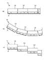
本例の遊技島1aは、図8(a)に示すように、この場合3台の遊技機2が片面側に並んで配置されるユニット島10を複数並べてなるものである。なお、各ユニット島10は、図8(a)に示すように、直線状に配列してもよいが、図8(b),(c)に示すように、円弧状に配列したり、段差をつけて配置したりすることもできる。これにより、従来困難であった特別な配列の遊技島1b,1cが容易に実現できる。
【0011】
B.ユニット島の全体構成
次に、図1乃至図3により、ユニット島10の全体構成について説明する。図1は、遊技機2(この場合スロットマシン)が設けられた完成状態のユニット島10の正面図であり、図2は、ユニット島の内部構成(特にコイン循環機構)を示した正面図である。また図3は、ユニット島の側断面図である。
ユニット島10は、図1又は図2に示すように、3台の遊技機2と2台のコイン貸機3が片面側(正面側)に取り付けられる島本体11と、この島本体11内に設けられて各遊技機2とコイン貸機3にコインを補給するコイン循環機構(後述する)とを、一体的に備えてユニット化されたものである。なお、ここでいうユニット化とは、独立の設備として事前に組み立てて搬送可能であり、しかも別個独立に設置してそれだけで運転可能なように、外形寸法や重量或いは構造等が設計されていることを意味する。
【0012】
島本体11は、図2又は図3に示す如く、主に、アルミニウムや鉄等の金属製長尺型材を略長方形状に組んで構成されたフレーム12(骨組み)と、このフレーム12の前面や後面或いは側面や上面に取り付けられて、島表面を装飾するとともに島内部を視認不能に覆う各種パネル類(本発明の表面板部材に相当)とよりなり、全体として外形が長方形状の箱形となっている。
この島本体11の正面側の下部には、水平状態に固定した棚板部材13が設けられ、この棚板部材13の上面側に、遊技機2やコイン貸機3が載置状態に設置される設置空間2a,3aが設けられている(図2参照)。なお、設置空間2a,3aの上面側には、図3に示すように、遊技機2等の上面に当接する止め板部材14が設けられ、遊技機2等が容易に外れないように、ビス止め等によってこの止め板部材14に遊技機2等が固定可能となっている。
【0013】
また、上記各種パネル類(表面板部材)としては、島の正面側における棚板部材13の下方を塞ぐ下部幕板15,16,17(図1参照)と、島の正面側における遊技機2等の上方を塞ぐ上部幕板18,19(図1参照)と、島の左右側面側を覆う側板20,21(図1参照)と、島の上面を覆う天板22,23(図1参照)と、島の後面を覆う後部幕板24(図3参照)などが、取り付けられる構成となっている。ここで、下部幕板15,16は、簡易な構成で容易に脱着できるように、後述する如く係合手段のみによってフレーム12に取り付けられている。一方、その他のパネル類(下部幕板17、上部幕板18,19、側板20,21など)は、基本的に、防犯性確保のため例えば多数のネジ部材等によって強固に取り付けられ固定されている。
なお、側板20,21の一方又は両方を取り外して、隣接するユニット島10の島本体11と接続してもよい。また、島本体11のフレーム12の底部には、遊技店の床(又は床に敷設した設置レール)の所定位置にユニット島10を設置して固定するためのアンカー部材(図示省略)が取り付け可能となっている。
【0014】
また、図1において、符号25で示すものは故障呼出ランプであり、符号26で示すものはユニット用報知装置であり、符号27で示すものは島端報知装置である。故障呼出ランプ25は、各遊技機2の故障を遊技店の店員等に報知するためのランプであり、例えば各遊技機2内の制御装置(図示省略)によって制御されて点灯するものである。ユニット用報知装置26は、ユニット島10の状態を遊技店の店員等に報知する表示器を備えた装置であり、ユニット島10の図示省略した制御装置(以下、ユニット島制御装置という)によって制御されて、表示動作(報知動作)を実行する。このユニット用報知装置26は、後述するように、本発明の投入部開閉状態報知手段としても機能する。島端報知装置27は、島の一方の端に位置するユニット島10にのみ設けられ、例えば各遊技機2内の制御装置(図示省略)によって制御されて点灯し、島内のいずれかの遊技機2が故障していることなどを遊技店の店員等に報知するものである。
また図1において、符号28で示すものは、ユニット島10に対してコインを補給するためのコイン投入部である。このコイン投入部28については、詳細を後述する。
【0015】
C.ユニット島のコイン循環機構の構成
次に、ユニット島10内のコイン循環機構は、図2に示すように、島本体11の図中左端側の下部に設けられ補給用のコインを貯留するコイン貯留部31と、このコイン貯留部31内のコインを揚送するコイン揚送装置32と、このコイン揚送装置32により揚送されるコインを整列した状態で島本体11の上部に案内する揚送レール33と、この揚送レール33の上端部から遊技機2の並び方向(図2における左右方向)に沿って下り傾斜した状態で島本体11の上部に架設された搬送レール34と、この搬送レール34に、遊技機2及びコイン貸機3に対応して設けられたコイン導入ゲート35と、搬送レール34を介して補給されるコイン数量を計数するためのコイン計数センサ36と、搬送レール34の傾斜下端から下方に向けて設けられ、全てのコイン導入ゲート35を通過したコインを島本体11の下部にオーバーフローさせるオーバーフロー流路37と、島本体11の図中右端側の下部に設けられこのオーバーフロー流路37を介して流下したコインを受けとめて貯留するサブコイン貯留部38と、このサブコイン貯留部38内のコインを揚送するコイン揚送装置39と、このコイン揚送装置39により揚送されるコインを整列した状態でコイン貯留部31に案内する移送レール40と、この移送レール40を通過するコイン数量を計数するためのコイン計数センサ41とを備える。
【0016】
ここで、コイン揚送装置32,39は、コイン貯留部31或いはサブコイン貯留部38の下部に形成されたホッパ状部(図示省略)にそれぞれ接続されて設置され、コイン貯留部31或いはサブコイン貯留部38内に貯留され前記ホッパ状部から供給されるコインを、モータ(図示省略)の回転力によって一枚ずつ押し上げる装置である。
揚送レール33は、コイン揚送装置32により揚送されるコインを、外周同士が当接した状態で一列に整列させて島本体11の上部に案内するレールであり、その上端部分には、揚送されるコインを揚送しながら研磨する研磨装置33aが設けられている。
搬送レール34は、コイン揚送装置32の作用によって揚送レール33内を上昇してきたコインを、重力の作用で下り傾斜方向(即ち、遊技機2の並び方向であって、図2における右方向)に一枚ずつ流下させるレールである。
コイン導入ゲート35は、搬送レール34に各遊技機2や各コイン貸機3に対応して設けられ、流下してきたコインを対応する遊技機2又はコイン貸機3に導入する状態(以下、開状態という)と、そのまま搬送レール34の下流側に通過させる状態(以下、閉状態という)とに切替可能なゲートである。
コイン計数センサ36は、搬送レール34の始端に設けられ、ここを通過するコインを一枚ずつ検出するセンサであり、コイン計数装置(各遊技機等に補給するコイン数量を計数する装置)を構成している。
オーバーフロー流路37は、搬送レール34の傾斜下端(図2における右端、搬送レール34の終端)から下方に向けて設けられ、全てのコイン導入ゲート35を通過したコイン(即ち、搬送レール34の傾斜下端まで流下してきたコイン)をサブコイン貯留部38内に流下させる流路である。
移送レール40は、搬送レール34と逆向きに下り傾斜した状態で島本体11の中程の高さに架設されたレールであり、コイン揚送装置39により揚送されたコインを、重力の作用で転動させ、後述するコイン貯留部31のコイン回収部31a(図6に示す)に一枚ずつ流下させるレールである。
【0017】
上記コイン循環機構は、前述したユニット島制御装置により制御されて動作して、次のようにユニット島10内のコインを循環させる構成となっている。
即ち、図1における左端側の遊技機2と中央の遊技機2に投入されてオーバーフローしたコインは、後述するコイン貯留部31のコイン回収部31a(図6に示す)に流下してコイン貯留部31内に回収される。一方、図1における右端側の遊技機2に投入されてオーバーフローしたコインは、サブコイン貯留部38の図示省略した回収口に流下してサブコイン貯留部38内に回収される。
そして、何れかの遊技機2又はコイン貸機3内のコイン貯留量(遊技機2等の内部に設けられたコイン排出装置によって排出可能なコイン数量)が所定量以下(例えば、約1000枚以下)になり、各遊技機2等にそれぞれ設けられた補給センサ(図示省略)がこれを検知すると、ユニット島制御装置が、該当するコイン導入ゲート35のみを閉状態から開状態に切り替えるとともに、コイン揚送装置32を作動させて、コイン補給動作を開始する。すると、コイン揚送装置32によって揚送されたコインが、揚送レール33と搬送レール34と該当するコイン導入ゲート35とを経由して該当する遊技機2又はコイン貸機3に送り込まれる(つまり、コイン貯留部31内のコインが該当する遊技機2等に補給される)。なお、このようなコイン補給動作は、コイン計数センサ36によって検出されたコインの数量(即ち、コインの補給数量)が所定数(例えば、1000枚)に到達したところで、停止される。なお、このコイン補給動作の停止は、該当するコイン導入ゲート35の状態を開状態から閉状態に戻すとともに、コイン揚送装置32を停止させることによって実現できる。また、該当するコイン導入ゲート35が閉状態に戻った直後に、搬送レール34に送り込まれてしまった余分なコインがあった場合、このコインは、搬送レール34を終端まで流下し、オーバーフロー流路37を経由して、サブコイン貯留部38内に回収される。
【0018】
また、ユニット島制御装置は、コイン貯留部31やサブコイン貯留部38内に設けられた貯留コインセンサ(コインの貯留量を検出するセンサであり、図示省略している)の出力を適宜読み取り、各貯留部におけるコイン貯留量のバランスを維持するためのコイン移送動作を必要に応じて実行する。具体的には、各貯留部のコイン貯留量が所定の目標量(例えば、コイン貯留部31に約1000枚、サブコイン貯留部38に約3000枚)近くに維持され、基本的にサブコイン貯留部38の貯留量が常に多くなるように、必要に応じて、コイン貯留部31からサブコイン貯留部38へのコイン移送動作、或いはサブコイン貯留部38からコイン貯留部31へのコイン移送動作を実行する。コイン貯留部31からサブコイン貯留部38へのコイン移送動作は、全てのコイン導入ゲート35を閉状態に維持したまま、コイン揚送装置32のみを作動させることによって実現できるし、サブコイン貯留部38からコイン貯留部31へのコイン移送動作は、コイン揚送装置39のみを作動させることによって実現できる。また、この際のコイン移送量のカウントは、コイン計数センサ36又は41の出力に基づいて可能である。なお、コイン貯留部31よりもサブコイン貯留部38の貯留量が常に多くなるように制御すると、コイン投入口28からコイン貯留部31内へのコインの投入(ユニット島10へのコインの補給)が円滑に行い易くなる。
【0019】
なお、上述したコイン補給動作(遊技機2等へのコイン補給)やコイン移送動作は、ユニット島制御装置の制御処理によって上述したように自動的に実行される構成に加えて、図示省略した手動操作部の操作によって手動で実行することができるようにしてもよい。
また、ユニット島制御装置は、コイン貯留部31やサブコイン貯留部38内のコイン貯留量を常に監視し、島内のコインの保有全量が例えば目標の貯留量よりも規定量以上少ない場合には、ユニット島10へのコイン補給が必要であるとして、コインが不足していることを報知すべく、図示省略した遊技店の管理装置にそのための信号を出力したり、前述したユニット用報知装置26に所定の報知動作を実行させたり、或いはさらに、前述した島端報知装置27を点灯させる機能を有する。
【0020】
D.ユニット島のコイン投入部の構成
次に、ユニット島10のコイン投入部28及びその周辺の構成について、図4乃至図7により説明する。ここで、図4は、コイン投入部28及びその周辺を示す斜視図(下部幕板15,16を外した状態)であり、図5は、コイン投入部28及びその周辺を示す斜視図(下部幕板15,16を取り付けた状態)である。また、図6は、コイン貯留部31のコイン回収部31aを示す平面図及び側面図であり、図7は前記コイン回収部31aを示す斜視図である。なお、図4及び図5においては、前述の棚板部材13を省略している。また、図4においては、島内部の機器(コイン揚送装置32等)の図示を省略している。
コイン投入部28は、図4に示すように、島本体11における下部幕板15,16の取付境界位置の上部(図1において、左端側の遊技機2と中央の遊技機2の間に位置するコイン貸機3の下方位置)に、抜き差し可能に設けられたスライド式の箱状部材である。このコイン投入部28を構成する箱状部材は、上面側と奥側が開口し、投入されたコインが奥側に流下するように底面28a(図3に示す)が奥側に向かって(前記コイン回収部31a内に向かって)下り傾斜しており、この傾斜した底面には、異物(ゴミや埃など)を落下させ排出するための図示省略した小孔(コインよりも小さい孔)が所定間隔で多数設けられている。ここで、コイン投入部28を構成する箱状部材の上方開口部28b(図4及び図5に示す)は、コイン投入口として機能し、ここからコインを投入する構成である。また、コイン投入部28を構成する箱状部材の前面板状部は、図4及び図5に示すように、外周部が周囲に張り出してつば状部28cを形成している。
【0021】
また、コイン投入部28には、前記上方開口部28bが閉じた状態(コイン投入部28を押し込んだ状態であり、本発明の閉状態に相当)に施錠する錠装置(図示省略)が備えられ、図4及び図5において、符号28dで示すものが、この錠装置(本発明の錠手段に相当)を操作するための鍵を挿入する鍵穴である。そして、島本体11のコイン投入部28の上方位置には、図4及び図5に示すように、直方体状の鍵係止部29が設けられている。ここで、前記錠装置は、例えば前記箱状部材側に設けられた回動片(図示省略)が、鍵穴28dから挿入された鍵の操作で回動して、鍵係止部29に設けられた係合溝(図示省略)に係合することで、前記上方開口部28bが閉じた状態を維持する(即ち、コイン投入部28を押し込んだ状態にて施錠する)ものである。
なおこの場合、コイン投入部28を押し込んだ閉状態では、コイン投入部28の前記つば状部28cの裏面が、島本体11に取り付けられた下部幕板15,16の前面縁部や、前記鍵係止部29の前面縁部に、部分的に当接するように構成されており(図3参照)、前記錠装置は、結果的に下部幕板15,16を取り外し不可能に施錠する錠手段としても機能する構成となっている。すなわち、この場合下部幕板15,16は、コイン揚送装置32などのメンテナンス作業が容易にできるように、島本体11に設けられた係合手段(例えば、図4に示す係合溝12aや係合片12b)と、下部幕板15,16に設けられた対応する係合手段(図示省略)とが、相互に係合又は離脱することによって、島本体11の骨組みを構成するフレーム12に対して、容易に脱着可能となっている(ネジ部材等は使用していない)。しかし、これら下部幕板15,16におけるコイン投入部28の周囲に位置するL字状切り欠き部15a,16a(図4に示す)の前面側縁部は、下部幕板15,16の取付状態において、コイン投入部28の前述のつば状部28cの内側(裏側)に入り込み(図5参照)、このコイン投入部28が押し込み状態(閉状態)にあると、前記つば状部28cの裏面に接合した状態になる。そしてこれにより、下部幕板15,16の動きが規制され、前述した係合手段の係合を解除させて下部幕板15,16を取り外すことができなくなる構成となっている。なお、図4及び図5において、符号15b,16bで示すものは、下部幕板15,16を着脱する際に作業者が指を挿入するための穴である。
【0022】
次に、コイン貯留部31のコイン回収部31aについて、図6及び図7により説明する。
コイン回収部31aは、コイン貯留部31の上部に形成された全体として箱形の部材であり、上面全体が開口するとともに、底面の一部(図2における前面左端側)に開口部31bが形成されている。開口部31bは、コイン貯留部31の下部に接続されており、ここから流下したコインは、最終的には前述したホッパ状部を経由してコイン揚送装置32に供給される。また、コイン回収部31aの底面には、最終的にコインを開口部31bに落下させるための複数の傾斜面31c〜31gが形成されている。ここで、傾斜面31cは、開口部31bからユニット島10の奥側に向かって上り傾斜した傾斜面であり、傾斜面31dは、開口部31bから遊技機2の並び方向(図2における右側)に向かって上り傾斜した傾斜面である。また、傾斜面31eは、傾斜面31dの奥側に配置されていて、傾斜面31cに向かって下り傾斜するように形成された傾斜面であり、傾斜面31dよりも一段高い位置に形成されている(図7参照)。また、傾斜面31fは、傾斜面31eのさらに奥側に配置されていて、傾斜面31cに向かって下り傾斜するように形成された傾斜面であり、傾斜面31eよりもさらに一段高い位置に形成されている。また、傾斜面31g(図6に示し、図7では省略している)は、開口部31bからユニット島10の手前側(正面側)に向かって上り傾斜した幅広で短い傾斜面であり、最も高い位置(コイン回収部31aの上縁部)に形成されている。
なお、図6(a)に示すように、各傾斜面31c〜31fには、前述したコイン投入部28の底面28aと同様に、異物(ゴミや埃など)を落下させ排出するための小孔Y(コインよりも小さい孔)が所定間隔で多数設けられている。
【0023】
そして、図1において左端側に位置する遊技機2からオーバーフローしたコインは、開口部31bに直接落下するか、傾斜面31gを経由して開口部31bに落下する構成となっている。また、図1において中央に位置する遊技機2からオーバーフローしたコインは、コイン回収部31aの図中右側の側面から延設されたコイン回収樋31h(図2及び図7に示す)を経由し、同側面に形成された開口部31i(図7に示す)を介して傾斜面31d上に流下し、この傾斜面31d上をさらに流下して、開口部31bに落下する構成となっている。
また、コイン投入部28の奥側端部は、コイン投入部28を押し込んだ状態(前記上方開口部28bが閉じた状態)において、コイン回収部31aの図中手前側の側面の右端側に形成された開口部31j(図6(b)に示す)を介して、コイン回収部31a内(正確には、傾斜面31e上)に奥深く挿入された状態となっており、コイン投入部28を相当量引き出した状態(前記上方開口部28bが開いた状態)においても、この挿入状態が相当の挿入深さで維持されるようになっている。これにより、コイン投入部28を相当量引き出して、前記上方開口部28bからコインを投入すると、このコインは、次のように流下して最終的に開口部31bに落下する構成となっている。即ち、コイン投入部28の奥側に下り傾斜する底面28a(図3に示す)の上面に沿って流下して、まず傾斜面31e上、或いは傾斜面31d上に落下する。次いで、図7に矢印Xで示すように、傾斜面31e或いは傾斜面31d上を流下し、開口部31bに落下する。
また、コイン揚送装置39によって移送レール40を経由してサブコイン貯留部38から移送されたコインは、図7に示すように、傾斜面31f上に落下する構成とされており、傾斜面31f上を流下し、次いで傾斜面31c上を流下して、開口部31bに落下する構成となっている。
【0024】
なお、図6(b)に示すように、コイン回収部31aの図中手前側の側面の左端側には、メンテナンス作業等のためにコイン貯留部31を開放するための開口部31kが形成されており、この開口部31kは、脱着可能な蓋部材51(図2に示す)によって開放可能に閉塞される構成となっている。またこの場合、この開口部31kを閉じる蓋部材51には、コイン貯留部31のコイン貯留量を検出する前述の貯留コインセンサが取り付けられるようになっている。
また、コイン回収部31a内におけるコイン投入部28の側面奥側に近接する位置には、押し込んだ状態にあるコイン投入部28を検出するコイン投入部検出センサ52(図3に示す)が設置されており、ユニット島制御装置において、コイン投入部28が押し込んだ状態に装着されていること、或いは所定量以上引き出されていることが判断できるように構成されている。即ち、このコイン投入部検出センサ52は、コイン投入部28の開閉状態を検出可能な本発明の投入部開閉検出手段を構成している。なお、このコイン投入部検出センサ52の出力に基づいて、ユニット島制御装置が、コイン投入部28の状態を報知する信号を遊技店の管理装置に送信したり、前述のユニット用報知装置26(投入部開閉状態報知手段)によってコイン投入部28の開閉状態を報知したりする構成となっており、これにより、コイン投入部28がまんがいち不正に引き出されてコインの不正な抜き出し等が行われていることを、容易かつ即座に発見して対処できるようになっている。
【0025】
E.本遊技島の特徴及び効果
以上説明したユニット島10からなる遊技島は、その特徴によって次のような各種の優れた効果を奏する。
(1)本形態例の遊技島は、遊技機2が所定の並び方向に複数並べて取り付けられる島本体11と、この島本体11に取り付けられた各遊技機2にコインを補給するコイン循環機構とを一体に備えて、ユニット化されたユニット島10よりなる。
このため、予め工場等で組み立てたユニット島10を、所定数だけ(1組だけでもよい)遊技店に搬入し、アンカー部材の取り付け等の据え付け作業を行えば、極めて短時間に新たな遊技島を設置でき、遊技店の稼働日の減少が回避できる。また、上記ユニット島10を任意のレイアウトで複数設置すれば、例えば図8(b)や図8(c)のように、従来困難であった遊技機2の特別な設置レイアウト(円弧状の配列、或いは段差のある配列等)が実現できて、遊技機2のファッション性を更に高めることができる。特に本例のように、遊技機2が数台だけ僅かに各ユニット島10に取り付けられる構成であると、ユニット島10が小型になり、新規設置作業がより楽になるとともに、遊技機2の設置レイアウトの自由度もより向上する。
【0026】
(2)しかも本形態例の遊技島では、錠手段の設けられたコイン投入部28が閉状態とされることによって、取付状態にある表面板部材(下部幕板15,16)が取り外し不能となる構成となっている。このため、表面板部材(下部幕板15,16)が不正に取り外されることに対する防犯性を容易に高めることができる。即ち、コイン投入部28の錠手段が表面板部材(下部幕板15,16)の錠手段としても機能するため、表面板部材(下部幕板15,16)の固定状態を強固なものにしたり(例えば、多数のネジ部材によって固定する構成にしたり)、表面板部材(下部幕板15,16)の取付状態維持のための錠手段を別個に設ける必要がなく、極めて簡素な構成で表面板部材(下部幕板15,16)が不正に取り外されることに対する防犯性を高められる。
特に、本実施の形態例では、コイン投入部28が閉状態とされると、コイン投入部28(正確には、つば状部28c)が前記表面板部材の動きを規制するという単純な構成によって、前記表面板部材の固定構造を達成している。また、二つの表面板部材(下部幕板15,16)が、一つのコイン投入部28によって施錠状態とされる。このため、特に構成が簡素化され、防犯性を向上させつつもコストをより低く抑えられる。
【0027】
(3)また、表面板部材(下部幕板15,16)は、係合手段のみによって係止状態に取り付けられる構成である。このため、コイン投入部28を開状態とすれば、表面板部材(下部幕板15,16)は、ワンタッチで容易に脱着可能であり、表面板部材(下部幕板15,16)を取り外す必要のあるメンテナンス作業(点検作業等も含む)が、非常に楽になるという実用上優れた効果も得られる。
(4)また、各ユニット島に設けられた複数の遊技機(好ましくは2乃至3台の遊技機)毎に、コイン循環機構が設置された構成となるので、一部のコイン循環機構に故障等が発生しても、その故障の影響は、そのコイン循環機構が一体に設けられた一つのユニット島における遊技機にしか及ばず、コイン循環機構の故障等の影響範囲が小さくなる利点も得られる。
【0028】
(5)また、コイン投入部28の閉状態(前述の押し込んだ状態)を維持可能な錠装置(錠手段)を備えるため、コイン投入部28からコインを奪う不正を信頼性高く防止できる。
(6)また、コイン投入部28が、スライド式に取り付けられる箱状部材よりなり、この箱状部材の上方開口部28bからコインを投入する構成であるため、コイン補給作業においてコインの投入が行い易く、またこの際にコインがこぼれる不具合が発生し難いという特長がある。
【0029】
(7)また、コイン投入部28の開閉状態を検出可能な投入部開閉検出手段(コイン投入部検出センサ52)と、この投入部開閉検出手段の検出結果に基づいてコイン投入部28の開閉状態を報知する投入部開閉状態報知手段(ユニット用報知装置26)とを備えている。このため、コイン投入部28がまんがいち不正に開けられても、遊技店の店員等が即座に発見して対応でき、さらに防犯性を高められる。
(8)特に本形態例では、投入部開閉状態報知手段(ユニット用報知装置26)が、島本体11において対応するコイン投入部28が設けられた面と同一の面に配設されている。このため、コイン投入部28との対応が一見して分かり易く、遊技店の店員等による不正(コイン投入部28の不正な開動)に対する監視がより確実になる。なお、このような構成は、図9(a)に示すように島の両側に遊技機(或いはコイン投入部)が設置されるタイプの場合に特に有効である。というのは、島の一方側のコイン投入部の状態が島の反対側で報知された場合には、どこのコイン投入部が開状態にあるのか即座に分からないし、店員等が現場に急行できない恐れがあるからである。
【0030】
なお、本発明は上記実施の形態の態様に限られず、各種の変形,応用があり得る。
例えば、ユニット島における遊技機の配置台数や配置レイアウトは、上記実施の形態の態様に限られない。例えば、図9(a)に示すように、島本体の両面側にそれぞれ2台の遊技機が並んで取り付けられるユニット島10aよりなる遊技島1dであってもよいし、或いは図9(b)に示すように、島本体の片面側に2台の遊技機が並んで取り付けられるユニット島10bよりなる遊技島1eであってもよい。また、遊技機が片面側に4台以上並べて設けられるユニット島からなるものであってもよい。
また、ユニット島におけるコイン貸機の配置台数や配置レイアウトも、上記実施の形態の態様に限られない。コイン貸機が設置されていないユニット島が含まれていてもよい。
また、遊技機等の配置台数や配置レイアウトの異なるユニット島が、複数設置されてなる遊技島であってもよい。
【0031】
また、閉状態にあるコイン投入部によって取り外し不能とされる表面板部材は、下部幕板に限られず、例えば上部幕板や側板であってもよい。この場合、上部幕板や側板の近傍にコイン投入部があれば、前記実施の形態と同様の構成(コイン投入部によって動きが規制される構成)によって、上部幕板や側板を固定状態に維持できる。また、上記実施の形態において、下部幕板17についても、コイン投入部28によって取り外しが規制される構成としてもよい。例えば、下部幕板16と下部幕板17を一体構造とすれば、容易に実現できる。
また、コイン投入部を閉状態とすることによって表面板部材が取り外し不能となる構成は、具体的に上記実施の形態のように、コイン投入部(又はこのコイン投入部と一体的に動く部材)が表面板部材の動きを単に規制することによって達成してもよいが、他の具体的構造によって達成することもできる。例えば、コイン投入部が閉状態となると、その動きに連動して表面板部材を係止させていた係合手段の係合要素が所定の機構によってロックされ、その結果、表面板部材の取付状態が係止状態から強固な固定状態(取り外しが不能な状態)に切り替わるような構造もあり得る。
【0032】
また、コイン投入部の設置位置や設置数も特に限定されず、例えばユニット島の端部にも、コイン投入部を設けてもよい。例えば、前記実施の形態のように、サブコイン貯留部38が設けられる場合、このサブコイン貯留部38に対してコインを投入するコイン投入部をさらに設けてもよい。なおこの場合、このサブコイン貯留部38に対するコイン投入部によって、上記実施の形態における下部幕板17或いは側板21の動きを規制して、これら表面板部材を固定状態に維持する構成としてもよい。
また、表面板状部(上記実施の形態における下部幕板15,16含む)は、必ずしも係合手段のみによって取り付けられる構成でなくてもよい。例えば、メンテナンス作業のために取り外す必要のあるものでも、ネジ止め(螺合手段)によって取り付けられていてもよい。この場合でも、最終的にコイン投入部によって固定状態に維持される表面板部材については、そのネジ止めのためのネジ部材の数(ネジ止め箇所の数)が極めて少なくてよい(1〜2本でもよい)ので、脱着容易性を相当高められる。
また、前記実施の形態では、サブコイン貯留部38と、これに対応した二台目のコイン揚送装置39とを別途設けた構成を例示したが、これらサブコイン貯留部38や二台目のコイン揚送装置39を設けない構成もあり得る。即ち、例えばオーバーフロー流路37を経由したコインが、直接にコイン貯留部31に流下し、また各遊技機2からオーバーフローしたコインが全てコイン貯留部31に流下する構成としてもよい。
【0033】
また、本発明の遊技島には、一組のユニット島からなるものも含まれる。
また、本発明における遊技機は、コイン状の遊技価値媒体(コイン、或いは、メダルと呼ばれるもの)を賞特典として排出する遊技機であり、このような遊技機であればスロットマシン以外の遊技機も含まれる。
また、本発明におけるコイン投入部は、島内のコイン保有数が多すぎる場合にコインを取り出すためのコイン取出口として機能してもよいことはいうまでもない。
また、今回開示された実施の形態はすべての点で例示であって制限的なものではないと考えられるべきである。本発明の範囲は上記した説明ではなくて特許請求の範囲によって示され、特許請求の範囲と均等の意味及び範囲内でのすべての変更が含まれることが意図される。
【0034】
【発明の効果】
請求項1記載の遊技島は、錠手段の設けられたコイン投入部が閉状態とされることによって、取付状態にある下部幕板が取り外し不能となる構成となっている。このため、下部幕板が不正に取り外されることに対する防犯性を容易に高めることができる。即ち、コイン投入部の錠手段が下部幕板の錠手段としても機能するため、下部幕板の固定状態を強固なものにしたり(例えば、多数のネジ部材によって固定する構成にしたり)、下部幕板の取付状態維持のための錠手段を別個に設ける必要がなく、極めて簡素な構成で下部幕板が不正に取り外されることに対する防犯性を高められる。
【0035】
また、請求項2記載の遊技島では、コイン投入部の開閉状態を検出可能な投入部開閉検出手段と、この投入部開閉検出手段の検出結果に基づいてコイン投入部の開閉状態を報知する投入部開閉状態報知手段とを備えている。このため、コイン投入部がまんがいち不正に開けられても、遊技店の店員等が即座に発見して対応でき、さらに防犯性を高められる。
【図面の簡単な説明】
【図1】 ユニット島の構成を示す正面図である。
【図2】 ユニット島のコイン循環機構を示す正面図である。
【図3】 ユニット島の構成を示す側面図である。
【図4】 コイン投入部とその周辺構成(下部幕板を外した状態)を示す斜視図である。
【図5】 コイン投入部とその周辺構成(下部幕板を付けた状態)を示す斜視図である。
【図6】 コイン貯留部のコイン回収部を示す平面図及び側面図である。
【図7】 コイン貯留部のコイン回収部を示す斜視図である。
【図8】 遊技島の全体構成を示す図である。
【図9】 遊技島の全体構成の他の例を示す図である。
【符号の説明】
1a〜1e 遊技島
2 遊技機(スロットマシン)
2a 遊技機の設置空間(遊技機取付部)
10,10a,10b ユニット島
11 島本体
15,16,17 下部幕板
26 ユニット用報知装置(投入部開閉状態報知手段)
28 コイン投入部
28a コイン投入部の底面
28b コイン投入部の上方開口部
28c つば状部
29 鍵係止部
31 コイン貯留部(コイン循環機構)
31b 開口部
31c 傾斜面(第1傾斜面)
31e 傾斜面(第2傾斜面)
31f 傾斜面(第3傾斜面)
32,39 コイン揚送装置(コイン循環機構)
33 揚送レール(コイン循環機構)
34 搬送レール(コイン循環機構)
35 コイン導入ゲート(コイン循環機構)
36,41 コイン計数センサ(コイン循環機構)
37 オーバーフロー流路(コイン循環機構)
38 サブコイン貯留部(コイン循環機構)
40 移送レール(コイン循環機構)
52 コイン投入部検出センサ(投入部開閉検出手段)[0001]
BACKGROUND OF THE INVENTION
The present invention relates to a gaming island in which a plurality of gaming machines (for example, slot machines) using coins (coin-like gaming value medium) are installed side by side.
[0002]
[Prior art]
For example, as is well known, a slot machine starts a game on condition that a player inserts coins for gaming, and a plurality of scrolled symbols are in a predetermined mode (for example, “777”). When stopped, the coin discharge device provided inside operates to discharge a predetermined amount of coins as a prize privilege (that is, coin award). Such gaming machines using coins such as slot machines are particularly welcomed by young people because they are more fashionable than pachinko machines.
[0003]
By the way, this kind of gaming machine in a game store is provided in a row on one or both sides of a facility called a gaming island or a gaming machine installation island (hereinafter simply referred to as an island) in the same manner as a pachinko machine. Conventionally, this gaming island is a horizontally long one to which a dozen or
[0004]
In addition, when the total amount of coins held in the island is reduced by coin award, the coin insertion unit for appropriately supplying coins to the entire island (that is, to the coin circulation device), Conventionally, it was provided only at the end of such a long island. In addition, various surface plate members (panels) that cover the surface of the island (such as around the gaming machine mounting portion) for decoration and crime prevention are individually attached to the frame of the island (frame) by fixing means such as screw members. At the time of maintenance work on the island equipment (for example, equipment constituting the coin circulation device), the fixing means of the corresponding surface plate member is removed and the fixed state of the surface plate member is individually released. Had to do.
[0005]
[Problems to be solved by the invention]
For this reason, the conventional game island such as the slot machine described above has the following problems.
That is, conventionally, since the fixing of the surface plate member is realized individually by a fixing means such as a screw member, it is difficult to easily realize high crime prevention, and the ease of maintenance work is enhanced. There was a limit.
This is because in order to reliably prevent fraud such as stealing the eyes of the capacity of amusement store and removing the surface plate member and extracting coins on the island, a large number of the above fixing means are provided or the surface plate member is fixed. This is because it is necessary to provide a locking means for individually locking the state for each surface plate member, which makes the structure complicated and increases the cost. In addition, for the above-described coin insertion portion, it is usually necessary to naturally provide a locking means for maintaining the closed state in order to prevent unauthorized withdrawal of coins from here, but separately from this, the surface plate member If there is a structure that also installs the lock means, a large number of lock means will be provided on one island, the facility cost of the island will increase, and the management of the keys corresponding to each lock means will be quite troublesome become.
[0006]
Further, when the surface plate member is individually fixed by a fixing means such as a screw member, the work of removing the surface plate member becomes troublesome, and the maintenance work that requires the removal of the surface plate member becomes difficult. . For example, the main equipment of a coin circulation device (a storage unit that stores coins, a lifting device that sends out coins, etc.) needs to be regularly inspected in addition to dealing with failures such as clogging of coins. In the place where such a device is provided, the surface plate member needs to be easily removed so that maintenance work (including replacement work and inspection work of the device) can be easily performed. However, conventionally, since the surface plate members are individually fixed by the original fixing means even at a place where such a device is provided, the operator first removes the fixing means (fixing screw member). For example, it is difficult to improve the ease of the maintenance work in this respect. In particular, in order to improve crime prevention as described above, when a large number of fixing means are provided or a lock means is provided for each surface plate member, the structure becomes complicated and the work of removing the surface plate member becomes more troublesome. Therefore, there is a problem that the ease of maintenance work is greatly deteriorated.
[0007]
Accordingly, the present invention provides an amusement island in which crime prevention is easily enhanced by fixing the surface plate member with a simple and inexpensive structure without deteriorating the ease of attaching / detaching the surface plate member (ease of maintenance work). The purpose is to provide.
[0008]
[Means for Solving the Problems]
In order to achieve the above object, the gaming island according to claim 1 is an island main body on which a plurality of gaming machines for discharging coins are mounted side by side as award benefits, and a coin circulation that is provided in the island main body to supply coins to each gaming machine. An amusement island equipped with a mechanism,
The coin circulation mechanism is
A coin storage part that is provided in the lower part of the island body and stores a coin for replenishmentAnd a transfer rail for guiding coins to the coin storage unit,
Including
The island body
A removable lower curtain that is provided so as to cover the lower part of the island body,
A coin insertion part that slides in the upper part of the lower curtain plate so that it can be inserted and removed and flows down toward the coin storage part.
A key locking portion that locks in a state in which the coin insertion portion is pushed in by engaging a locking means provided in the coin insertion portion;
With
The coin insertion portion is made of a box-shaped member and is configured to insert coins from the upper opening of the box-shaped member, and the front plate-shaped portion of the box-shaped member protrudes to form a collar-shaped portion. And
Lower curtainBoardIs provided with a front side edge portion where the back surface of the collar portion is joined when the coin insertion portion is locked in the depressed state, and the movement is restricted and the removal is impossible.And
The coin storage unit
A first inclined surface inclined downward toward the opening formed in the bottom;
A second inclined surface and a third inclined surface inclined downward toward the first inclined surface;
Have
Forming the third inclined surface at a position one step higher than the second inclined surface;
The coins inserted from the coin insertion portion flow down on the second inclined surface, while the coins that roll in an aligned state are caused to flow down on the third inclined surface by the transfer rail.It is characterized by that.
[0009]
In addition, the game island according to
An insertion portion opening / closing state notifying means for notifying an opening / closing state of the coin insertion portion based on a detection result of the insertion portion opening / closing detection means is provided.
[0010]
DETAILED DESCRIPTION OF THE INVENTION
Hereinafter, an example of an embodiment of the present invention will be described with reference to the drawings.
A. Schematic configuration of the entire amusement island
First, a schematic configuration of the entire amusement island will be described. Fig.8 (a) is a top view which shows the whole island, FIG. 1 is a front view of the unit island which comprises an island.
As shown in FIG. 8A, the
[0011]
B. Overall structure of unit island
Next, the overall configuration of the
As shown in FIG. 1 or FIG. 2, the
[0012]
As shown in FIG. 2 or FIG. 3, the
A
[0013]
The various panels (surface plate members) include
One or both of the
[0014]
Moreover, in FIG. 1, what is shown with the code |
Further, in FIG. 1, what is indicated by
[0015]
C. Configuration of coin circulation mechanism on unit island
Next, as shown in FIG. 2, the coin circulation mechanism in the
[0016]
Here, the
The lifting
The
The
The
The
The
[0017]
The coin circulation mechanism operates under the control of the unit island control device described above and circulates coins in the
That is, coins that have been thrown into the
Then, the coin storage amount in any of the
[0018]
Further, the unit island control device appropriately reads the output of a stored coin sensor (not shown) that is provided in the
[0019]
Note that the above-described coin replenishment operation (coin replenishment to the
Further, the unit island control device always monitors the coin storage amount in the
[0020]
D. Composition of coin insertion part of unit island
Next, the
As shown in FIG. 4, the
[0021]
Further, the
In this case, in the closed state in which the
[0022]
Next, the
The
As shown in FIG. 6 (a), each of the
[0023]
And the coin which overflowed from the
Further, the rear end portion of the
Further, as shown in FIG. 7, the coin transferred from the sub
[0024]
As shown in FIG. 6B, an
Further, a coin insertion portion detection sensor 52 (shown in FIG. 3) for detecting the
[0025]
E. Features and effects of this game island
The amusement island made up of the
(1) The gaming island of this embodiment includes an island
For this reason, if a predetermined number (or only one set) of
[0026]
(2) Moreover, in the gaming island of this embodiment, the coin-inserting
In particular, in this embodiment, when the
[0027]
(3) Further, the surface plate members (
(4) Also, since a coin circulation mechanism is installed for each of a plurality of gaming machines (preferably 2 to 3 gaming machines) provided on each unit island, some coin circulation mechanisms may fail. However, the effect of the failure only affects the gaming machine on one unit island in which the coin circulation mechanism is integrally provided, and there is an advantage that the influence range of the failure of the coin circulation mechanism is reduced. It is done.
[0028]
(5) In addition, since the lock device (locking means) capable of maintaining the closed state of the coin insertion unit 28 (the above-described pushed state) is provided, fraud in which a coin is taken from the
(6) Further, since the
[0029]
(7) Also, an insertion portion opening / closing detection means (coin insertion portion detection sensor 52) capable of detecting the opening / closing state of the
(8) Particularly in the present embodiment, the insertion portion open / close state notification means (unit notification device 26) is disposed on the same surface of the
[0030]
In addition, this invention is not restricted to the aspect of the said embodiment, There can be various deformation | transformation and application.
For example, the number and arrangement layout of gaming machines on a unit island are not limited to the aspects of the above embodiment. For example, as shown in FIG. 9 (a), it may be a
Further, the number and arrangement layout of coin lending machines on the unit island are not limited to the above-described embodiments. Unit islands where no coin lending machine is installed may be included.
Further, a gaming island in which a plurality of unit islands having different arrangement numbers and arrangement layouts of gaming machines or the like may be installed.
[0031]
Further, the surface plate member that cannot be removed by the coin insertion portion in the closed state is not limited to the lower curtain plate, and may be an upper curtain plate or a side plate, for example. In this case, if there is a coin insertion portion in the vicinity of the upper curtain plate or the side plate, the upper curtain plate or the side plate is maintained in a fixed state by the same configuration as the above embodiment (a configuration in which movement is regulated by the coin insertion portion). it can. Further, in the above-described embodiment, the
Further, the configuration in which the surface plate member cannot be removed by closing the coin insertion portion is specifically a coin insertion portion (or a member that moves integrally with the coin insertion portion) as in the above embodiment. May be achieved simply by restricting the movement of the faceplate member, but may also be achieved by other specific structures. For example, when the coin insertion portion is in the closed state, the engagement element of the engagement means that has locked the surface plate member in conjunction with the movement is locked by a predetermined mechanism, and as a result, the attachment state of the surface plate member There may be a structure in which is switched from a locked state to a firmly fixed state (a state in which removal is impossible).
[0032]
Moreover, the installation position and the number of installation of the coin insertion unit are not particularly limited, and for example, a coin insertion unit may be provided at the end of the unit island. For example, when the sub
Further, the surface plate-like portion (including the
In the above embodiment, the sub
[0033]
In addition, the game island of the present invention includes a set of unit islands.
The gaming machine according to the present invention is a gaming machine that discharges a coin-like gaming value medium (coin or a so-called medal) as an award privilege. If such a gaming machine, a gaming machine other than a slot machine is used. Is also included.
In addition, it goes without saying that the coin insertion portion in the present invention may function as a coin outlet for taking out coins when the number of coins held on the island is too large.
In addition, it should be considered that the embodiment disclosed this time is illustrative and not restrictive in all respects. The scope of the present invention is defined by the terms of the claims, rather than the description above, and is intended to include any modifications within the scope and meaning equivalent to the terms of the claims.
[0034]
【The invention's effect】
The gaming island according to claim 1 is configured such that the lower curtain plate in the attached state cannot be removed by closing the coin insertion portion provided with the locking means. For this reason, it is possible to easily improve crime prevention against the unauthorized removal of the lower curtain. That is, since the locking means of the coin insertion portion also functions as the locking means of the lower curtain plate, the lower curtain plate is firmly fixed (for example, configured to be fixed by a large number of screw members), or the lower curtain plate is fixed. There is no need to separately provide a locking means for maintaining the mounting state of the plate, and the crime prevention property against the unauthorized removal of the lower curtain is improved with a very simple configuration.
[0035]
In addition, in the gaming island according to
[Brief description of the drawings]
FIG. 1 is a front view showing a configuration of a unit island.
FIG. 2 is a front view showing a coin circulation mechanism of a unit island.
FIG. 3 is a side view showing a configuration of a unit island.
FIG. 4 is a perspective view showing a coin insertion portion and its peripheral configuration (a state where a lower curtain is removed).
FIG. 5 is a perspective view showing a coin insertion portion and its peripheral configuration (a state in which a lower curtain plate is attached).
6A and 6B are a plan view and a side view showing a coin collecting unit of the coin storing unit.
FIG. 7 is a perspective view showing a coin collecting unit of the coin storing unit.
FIG. 8 is a diagram showing an overall configuration of amusement islands.
FIG. 9 is a diagram showing another example of the entire configuration of the game island.
[Explanation of symbols]
1a-1e Yugijima
2 Game machines (slot machines)
2a Gaming machine installation space (gaming machine mounting part)
10, 10a, 10b Unit Island
11 Island body
15, 16, 17 Lower curtain
26 Unit reporting device (loading unit opening / closing status reporting means)
28 Coin slot
28a Bottom of coin insertion
28b Upper opening of coin insertion part
28c collar
29 Key lock
31 Coin storage (coin circulation mechanism)
31b opening
31c inclined surface (first inclined surface)
31e inclined surface (second inclined surface)
31f inclined surface (third inclined surface)
32,39 Coin lifting device (coin circulation mechanism)
33 Lifting rail (coin circulation mechanism)
34 Transport rail (coin circulation mechanism)
35 Coin introduction gate (coin circulation mechanism)
36, 41 Coin counting sensor (coin circulation mechanism)
37 Overflow channel (coin circulation mechanism)
38 Subcoin storage (coin circulation mechanism)
40 Transfer rail (coin circulation mechanism)
52 Coin insertion portion detection sensor (insertion portion opening / closing detection means)
Claims (2)
前記コイン循環機構は、
前記島本体の下部に設けられて、補給用のコインを貯留するコイン貯留部と、該コイン貯留部にコインを案内する移送レールと、
を含み、
前記島本体は、
当該島本体の下部を塞ぐように設けられる脱着自在な下部幕板と、
前記下部幕板の上部にて抜き差し可能にスライドし、引き出した状態で投入されたコインを前記コイン貯留部に向かって流下させるコイン投入部と、
前記コイン投入部に設けられた錠手段に係合してコイン投入部を押し込んだ状態に施錠する鍵係止部と、
を備え、
前記コイン投入部は、箱状部材よりなってこの箱状部材の上方開口部からコインを投入するように構成するとともに、当該箱状部材の前面板状部が周囲に張り出してつば状部を形成し、
前記下部幕板は、前記コイン投入部が押し込んだ状態に施錠されると前記つば状部の裏面が接合する前面側縁部を設けることにより、動きが規制されて取り出し不能とし、
前記コイン貯留部は、
底に形成された開口部に向かって下り傾斜した第1傾斜面と、
該第1傾斜面に向かって下り傾斜する第2傾斜面及び第3傾斜面と、
を有し、
前記第3傾斜面を前記第2傾斜面より一段高い位置に形成し、
前記第2傾斜面には前記コイン投入部から投入されたコインを流下させ、一方、前記第3傾斜面には前記移送レールにより整列状態で転動するコインを流下させることを特徴とする遊技島。A game island comprising an island body to which a plurality of gaming machines for discharging coins are mounted side by side as an award privilege, and a coin circulation mechanism provided in the island body for supplying coins to each gaming machine,
The coin circulation mechanism is
A coin storage part that is provided in a lower part of the island main body and stores coins for supply; a transfer rail that guides the coins to the coin storage part;
Including
The island body
A removable lower curtain that is provided so as to cover the lower part of the island body,
A coin insertion part that slides in the upper part of the lower curtain plate so that it can be inserted and removed and flows down toward the coin storage part.
A key locking portion that locks in a state in which the coin insertion portion is pushed in by engaging a locking means provided in the coin insertion portion;
With
The coin insertion portion is made of a box-shaped member and is configured to insert coins from the upper opening of the box-shaped member, and the front plate-shaped portion of the box-shaped member protrudes to form a collar-shaped portion. And
The lower blade plate by providing a front-side edge of the rear surface is joined to said flange portion and the coin insertion portion is locked in a state pushed, and irretrievable in motion is restricted,
The coin storage unit
A first inclined surface inclined downward toward the opening formed in the bottom;
A second inclined surface and a third inclined surface inclined downward toward the first inclined surface;
Have
Forming the third inclined surface at a position one step higher than the second inclined surface;
The game island is characterized in that coins inserted from the coin insertion portion flow down on the second inclined surface, while coins that roll in an aligned state by the transfer rail flow down on the third inclined surface. .
この投入部開閉検出手段の検出結果に基づいて前記コイン投入部の開閉状態を報知する投入部開閉状態報知手段とを備えたことを特徴とする請求項1記載の遊技島。An insertion portion opening / closing detection means capable of detecting an open / closed state of the coin insertion portion;
2. The game island according to claim 1, further comprising insertion portion opening / closing state notifying means for notifying an opening / closing state of the coin insertion portion based on a detection result of the insertion portion opening / closing detection means.
Priority Applications (1)
| Application Number | Priority Date | Filing Date | Title |
|---|---|---|---|
| JP2000144818A JP4230092B2 (en) | 2000-05-17 | 2000-05-17 | Yugi Island |
Applications Claiming Priority (1)
| Application Number | Priority Date | Filing Date | Title |
|---|---|---|---|
| JP2000144818A JP4230092B2 (en) | 2000-05-17 | 2000-05-17 | Yugi Island |
Publications (3)
| Publication Number | Publication Date |
|---|---|
| JP2001321548A JP2001321548A (en) | 2001-11-20 |
| JP2001321548A5 JP2001321548A5 (en) | 2005-03-17 |
| JP4230092B2 true JP4230092B2 (en) | 2009-02-25 |
Family
ID=18651413
Family Applications (1)
| Application Number | Title | Priority Date | Filing Date |
|---|---|---|---|
| JP2000144818A Expired - Fee Related JP4230092B2 (en) | 2000-05-17 | 2000-05-17 | Yugi Island |
Country Status (1)
| Country | Link |
|---|---|
| JP (1) | JP4230092B2 (en) |
Families Citing this family (3)
| Publication number | Priority date | Publication date | Assignee | Title |
|---|---|---|---|---|
| JP4518245B2 (en) * | 2004-04-01 | 2010-08-04 | サミー株式会社 | Bullet ball machine |
| JP6041283B1 (en) * | 2016-05-23 | 2016-12-07 | 株式会社大都製作所 | Medals supply device |
| JP6098909B1 (en) * | 2016-05-23 | 2017-03-22 | 株式会社大都製作所 | Medals supply device |
-
2000
- 2000-05-17 JP JP2000144818A patent/JP4230092B2/en not_active Expired - Fee Related
Also Published As
| Publication number | Publication date |
|---|---|
| JP2001321548A (en) | 2001-11-20 |
Similar Documents
| Publication | Publication Date | Title |
|---|---|---|
| EP1416453B1 (en) | Gaming machine with bill insertion slot | |
| JP2005040572A (en) | Recovery tank for game machine | |
| JP4230092B2 (en) | Yugi Island | |
| JP3616015B2 (en) | Auxiliary storage case and game machine using the same | |
| JP2016168497A (en) | Game machine | |
| JP2001321548A5 (en) | ||
| JP4825893B2 (en) | Game machine | |
| JPH11313976A (en) | Counter per machine fur pachinko machine | |
| JP2015006468A (en) | Game machine | |
| JP5050541B2 (en) | Game machine | |
| JP5022402B2 (en) | Game machine | |
| JP4065294B2 (en) | Counting device and arrangement method of counting device | |
| JP4444793B2 (en) | Game table, game system, and method for preventing illegal acts of game table | |
| JP2001321547A (en) | Game island | |
| JP4135804B2 (en) | Yugi Island | |
| JP2002000871A (en) | Game machine | |
| JP2001340618A5 (en) | ||
| JP2016190095A (en) | Game machine | |
| JP5135788B2 (en) | Game machine | |
| JP4572416B2 (en) | Game machine | |
| JP4213088B2 (en) | Game machine | |
| JP2001340621A (en) | Game island | |
| JP2012135678A (en) | Game machine | |
| JP5219500B2 (en) | Amusement machine island | |
| JP2005287868A (en) | Pachinko game machine |
Legal Events
| Date | Code | Title | Description |
|---|---|---|---|
| A521 | Written amendment |
Free format text: JAPANESE INTERMEDIATE CODE: A523 Effective date: 20040423 |
|
| A621 | Written request for application examination |
Free format text: JAPANESE INTERMEDIATE CODE: A621 Effective date: 20040423 |
|
| A131 | Notification of reasons for refusal |
Free format text: JAPANESE INTERMEDIATE CODE: A131 Effective date: 20080311 |
|
| A977 | Report on retrieval |
Free format text: JAPANESE INTERMEDIATE CODE: A971007 Effective date: 20080314 |
|
| A521 | Written amendment |
Free format text: JAPANESE INTERMEDIATE CODE: A523 Effective date: 20080416 |
|
| TRDD | Decision of grant or rejection written | ||
| A01 | Written decision to grant a patent or to grant a registration (utility model) |
Free format text: JAPANESE INTERMEDIATE CODE: A01 Effective date: 20081202 |
|
| A01 | Written decision to grant a patent or to grant a registration (utility model) |
Free format text: JAPANESE INTERMEDIATE CODE: A01 |
|
| A61 | First payment of annual fees (during grant procedure) |
Free format text: JAPANESE INTERMEDIATE CODE: A61 Effective date: 20081203 |
|
| R150 | Certificate of patent or registration of utility model |
Free format text: JAPANESE INTERMEDIATE CODE: R150 |
|
| FPAY | Renewal fee payment (event date is renewal date of database) |
Free format text: PAYMENT UNTIL: 20111212 Year of fee payment: 3 |
|
| FPAY | Renewal fee payment (event date is renewal date of database) |
Free format text: PAYMENT UNTIL: 20141212 Year of fee payment: 6 |
|
| LAPS | Cancellation because of no payment of annual fees |