JP2004124841A - Failure diagnosis device for vehicle - Google Patents
Failure diagnosis device for vehicle Download PDFInfo
- Publication number
- JP2004124841A JP2004124841A JP2002290948A JP2002290948A JP2004124841A JP 2004124841 A JP2004124841 A JP 2004124841A JP 2002290948 A JP2002290948 A JP 2002290948A JP 2002290948 A JP2002290948 A JP 2002290948A JP 2004124841 A JP2004124841 A JP 2004124841A
- Authority
- JP
- Japan
- Prior art keywords
- failure
- engine
- control unit
- vehicle
- driving force
- Prior art date
- Legal status (The legal status is an assumption and is not a legal conclusion. Google has not performed a legal analysis and makes no representation as to the accuracy of the status listed.)
- Pending
Links
Images

Abstract
Description
【0001】
【発明の属する技術分野】
本発明は、車両の故障診断装置の改良に関するものである。
【0002】
【従来の技術】
車両にはエンジンや変速機、制動装置等に故障が発生したことを報知する警告灯が配設されており、センサやアクチュエータなどの部材や油圧などに故障(または異常)が生じた場合、コントローラがこの故障を検出して、運転者が視認可能な位置に設けた警告灯を点灯または点滅させて、故障が発生したことを報知するものが知られている(例えば、特許文献1参照)。
【0003】
【特許文献1】
実用新案登録第2571903号公報(第2頁)
【0004】
【発明が解決しようとする課題】
しかしながら、上記従来例においては、運転者には単に故障が発生した、という情報のみが伝えられることになり、故障の程度や故障が発生した箇所あるいは原因については伝達されない。
【0005】
このため、運転者は故障の程度、換言すれば、大至急修理が必要な状態であるのか、軽微な故障(その時点では車両の走行には大きな影響を与えない故障)であるのか分からないために、不要な不安感を与える場合があり、特に、深夜の走行中では、運転者に大きな負担となる場合があった。
【0006】
また、上記従来例では、即座に重大な故障を引き起こすことはないが、この故障状態を放置して長期間にわたり走行を続けると、重大な故障を招く恐れがある軽微な故障でも警告灯の点灯を行うため、運転者は迅速に修理を行うべきか、都合の良いときに修理を行えばよいのか容易に判断することはできない、という問題もあった。
【0007】
そこで、本発明は上記問題点に鑑みてなされたもので、故障が発生した場合であっても運転者に不要な不安感を与えることなく故障の報知を行うことを目的とする。
【0008】
【課題を解決するための手段】
第1の発明は、エンジン及び自動変速機を制御する駆動力制御手段と、車両の各部位の故障を検出する故障検出手段とを備えた、車両の故障診断装置において、
前記駆動力制御手段は、前記故障が検出されたときに駆動力の低減または駆動力の応答性を低下させて故障の報知を行う故障報知手段を含む。
【0009】
また、第2の発明は、前記第1の発明において、前記駆動力制御手段は、エンジンの出力を制御するエンジン制御手段と、自動変速機の変速比及び油圧を制御する変速制御手段からなり、前記故障報知手段は、故障が検出されたときには、エンジンの出力を低減する。
【0010】
また、第3の発明は、前記第1の発明において、前記駆動力制御手段は、エンジンの出力を制御するエンジン制御手段と、自動変速機の変速比及び油圧を制御する変速制御手段からなり、前記故障報知手段は、故障が検出されたときには、変速速度を低下させる。
【0011】
また、第4の発明は、前記第1の発明において、前記駆動力制御手段は、エンジンの出力を制御するエンジン制御手段と、自動変速機の変速比及び油圧を制御する変速制御手段からなり、前記故障報知手段は、エンジンの出力を低減するトルクダウン手段と、自動変速機の変速速度を低下させる変速速度低下手段と、前記故障を検出した部位に応じて、前記トルクダウン手段または変速速度低下手段のいずれか一方を選択する切換手段を備える。
【0012】
また、第5の発明は、前記第1ないし第4の発明のいずれか一つにおいて、前記故障検出手段は、前記自動変速機を構成する部材の故障を検出する。
【0013】
【発明の効果】
したがって本発明は、故障が発生すると、エンジントルクの低減により、加速性能や登坂性能が低下し、あるいは、変速速度が低減されることで、キックダウン時のダウンシフトに遅れが生じたり、足離しアップシフト時のエンジン回転速度の低下が遅れることから、変速機または駆動系の不調を体感することになる。運転者は必要最低限の走行には差し支えないものの、車両の動力性能の低下によって修理の必要性を感じることができ、これを故障の報知とすることで、前記従来例のように運転者に不安感を抱かせることなく、故障の報知を行うことが可能となるのである。
【0014】
【発明の実施の形態】
以下、本発明の一実施形態を添付図面に基づいて説明する。
【0015】
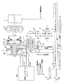
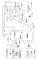
図1は、自動変速機としてVベルト式の無段変速機を採用した場合の概略構成図を示し、図2は油圧コントロールユニット及びCVTコントロールユニットの概念図をそれぞれ示す。
【0016】
図1において、自動変速機としての無段変速機5はロックアップクラッチを備えたトルクコンバータ2、前後進切り替え機構4を介してエンジン1に連結され、一対の可変プーリとして入力軸側のプライマリプーリ10、出力軸13に連結されたセカンダリプーリ11を備え、これら一対の可変プーリ10、11はVベルト12によって連結されている。なお、出力軸13はアイドラギア14及びアイドラシャフトを介してディファレンシャル6に連結される。
【0017】
無段変速機5の変速比やVベルトの接触摩擦力は、CVTコントロールユニット20からの指令に応動する油圧コントロールユニット100によって制御され、CVTコントロールユニット20は、エンジン1を制御するエンジンコントロールユニット21から得た入力トルク情報、エンジン回転速度や後述するセンサ等からの出力に基づいて変速比や接触摩擦力を決定し、制御する。なお、これらコントロールユニットは、マイクロコンピュータなどを主体に構成されている。
【0018】
無段変速機5のプライマリプーリ10は、入力軸と一体となって回転する固定円錐板10bと、固定円錐板10bに対向配置されてV字状のプーリ溝を形成するとともに、プライマリプーリシリンダ室10cへ作用する油圧(プライマリ圧)によって軸方向へ変位可能な可動円錐板10aから構成される。
【0019】
セカンダリプーリ11は出力軸13と一体となって回転する固定円錐板11bと、この固定円錐板11bに対向配置されてV字状のプーリ溝を形成するとともに、セカンダリプーリシリンダ室11cへ作用する油圧(セカンダリ圧)に応じて軸方向へ変位可能な可動円錐板11aから構成される。
【0020】
ここで、プライマリプーリシリンダ室10cとセカンダリプーリシリンダ室11cは、等しい受圧面積に設定される。
【0021】
エンジン1から入力された駆動トルクは、トルクコンバータ2、前後進切り替え機構4を介して無段変速機5へ入力され、プライマリプーリ10からVベルト12を介してセカンダリプーリ11へ伝達され、プライマリプーリ10の可動円錐板10a及びセカンダリプーリ11の可動円錐板11aを軸方向へ変位させて、Vベルト12との接触半径を変更することにより、プライマリプーリ10とセカンダリプーリ11との変速比を連続的に変更することができる。
【0022】
無段変速機5の変速比及びVベルト12の接触摩擦力は油圧コントロールユニット100によって制御される。
【0023】
図2に示すように、油圧コントロールユニット100は、ライン圧を制御するレギュレータバルブ60と、プライマリプーリシリンダ室10cの油圧(以下、プライマリ圧)を制御する変速制御弁30と、セカンダリプーリシリンダ室11cへの供給圧(以下、セカンダリ圧)を制御する減圧弁61を主体に構成される。
【0024】
変速制御弁30はメカニカルフィードバック機構を構成するサーボリンク50に連結され、サーボリンク50の一端に連結されたステップモータ(変速アクチュエータ)40によって駆動されるとともに、サーボリンク50の他端に連結したプライマリプーリ10の可動円錐盤10aから溝幅、つまり実変速比のフィードバックを受ける。
【0025】
ライン圧制御系は、油圧ポンプ80からの圧油を調圧するソレノイドを備えたレギュレータバルブ60で構成され、CVTコントロールユニット20からの指令(例えば、デューティ信号など)に応じて運転状態に応じた所定のライン圧PLに調圧する。
【0026】
ライン圧PLは、プライマリ圧を制御する変速制御弁30と、セカンダリ圧を制御するソレノイドを備えた減圧弁61にそれぞれ供給される。
【0027】
プライマリプーリ10とセカンダリプーリ11の変速比は、CVTコントロールユニット20からの変速指令信号に応じて駆動されるステップモータ40によって制御され、ステップモータ40に応動するサーボリンク50の変位に応じて変速制御弁30のスプール31が駆動され、変速制御弁30に供給されたライン圧PLが調整されてプライマリ圧をプライマリプーリ10へ供給し、溝幅が可変制御されて所定の変速比に設定される。
【0028】
なお、変速制御弁30は、スプール31の変位によってプライマリプーリシリンダ室10cへの油圧の吸排を行って、ステップモータ40の駆動位置で指令された目標変速比となるようにプライマリ圧を調整し、実際に変速が終了するとサーボリンク50からの変位を受けてスプール31を閉弁する。
【0029】
ここで、CVTコントロールユニット20は、図1において、無段変速機5のプライマリプーリ10の回転速度を検出するプライマリプーリ速度センサ(回転速度検出手段)26、セカンダリプーリ11の回転速度(または車速)を検出するセカンダリプーリ回転速度センサ27、セカンダリプーリのシリンダ室11cにかかるセカンダリ圧を検出する油圧センサ(油圧検出手段)28やプライマリプーリのシリンダ室10cにかかるプライマリ圧を検出する油圧センサ29、ブレーキスイッチ32からの信号と、インヒビタースイッチ23からのセレクト位置と、運転者が操作するアクセルペダルの操作量に応じた操作量センサ24からのストローク(または、アクセルペダルの開度)、油温センサ25から無段変速機5の油温を読み込んで、変速比やVベルト12の接触摩擦力を可変制御する。
【0030】
CVTコントロールユニット20では、予め設定したマップなどから車速やアクセルペダルのストロークに基づいて目標プライマリプーリ回転速度(目標入力軸回転速度)を求め、この目標プライマリプーリ回転速度と検出したセカンダリプーリ回転速度の比を目標変速比とし、実変速比が目標変速比に一致するように、ステップモータ40を所定の速度(パルスレート≒変速速度)で駆動する変速制御部201と、エンジンコントロールユニット21から得た入力トルク(エンジントルク)や変速比、油温、変速速度などに応じて、プライマリプーリ10とセカンダリプーリ11の推力(接触摩擦力)を制御するプーリ圧(油圧)制御部202から構成される。
【0031】
プーリ圧制御部202は、入力トルク情報、プライマリプーリ回転速度とセカンダリプーリ回転速度に基づく変速比、油温からライン圧の目標値を決定し、レギュレータバルブ60のソレノイドを駆動することでライン圧の制御を行い、また、セカンダリ圧の目標値を決定して、油圧センサ28の検出値と目標値に応じて減圧弁61のソレノイドを駆動して、フィードバック制御(閉ループ制御)によりセカンダリ圧を制御する。
【0032】
さらに、プーリ圧制御部202では、Vベルト12に滑りを生じるような運転状態、例えば、油温が極めて低く作動油の粘度大きいために油圧ポンプ80からの供給圧が上がらず、プライマリプーリ10及びセカンダリプーリ11のVベルト12を挟持する力が不足してVベルト12に滑りを生じるようなときには、油圧センサ28が検出した油圧(セカンダリ圧)と変速比(プーリ比)に基づいてトルク容量(伝達可能なトルク)を求めるとともに、無段変速機5の入力トルクを求め、入力トルクとトルク容量の差に基づいてトルクダウン量を決定し、エンジンコントロールユニット21へトルクダウン要求値を送信するトルクダウン要求を行う。
【0033】
ここで、本発明のCVTコントロールユニット20には、前記従来例のような警告灯やブザーなどで故障報知を行う装置は配設されておらず、以下に示す制御により、無段変速機5に故障があった場合には、車両の挙動を変更することで、運転者に故障を報知する。
【0034】
次に、CVTコントロールユニット20で行われる故障診断制御の一例について、図3のフローチャートを参照しながら詳述する。なお、図3のフローチャートは所定の周期、例えば、数十msec毎に実行されるものである。
【0035】
まず、ステップS1では、上記各センサから、プライマリ圧、セカンダリ圧、ブレーキスイッチの信号(ON/OFF)、油温、プライマリプーリ回転速度(入力軸回転速度)、セカンダリプーリ回転速度(出力軸回転速度または車速)、をそれぞれ読み込む。
【0036】
ステップS2では、上記ステップS1で読み込んだセンサの出力に基づいて、無段変速機5の故障検出を行う。
【0037】
この故障検出の一例としては、センサまたは油圧系統の故障を次のように検出する。
【0038】
A.プライマリ油圧センサ29
プライマリ油圧センサ29の出力電圧を監視して、出力電圧が所定の範囲を超えていれば故障と判定する。または、車両が走行中(車速>0[km/h])でセカンダリ圧>0[MPa]のとき、プライマリ圧=0[MPa]であればプライマリ油圧センサ29が故障していると判定してもよい。
【0039】
B.セカンダリ油圧センサ28
セカンダリ油圧センサ28の出力電圧を監視して、出力電圧が所定の範囲を超えていれば故障と判定する。または、車両が走行中(車速>0[Km/h])でプライマリ圧>0[MPa]のときセカンダリ圧=0[MPa]であれば、セカンダリ油圧センサ28が故障していると判定してもよい。
【0040】
C.ブレーキスイッチ32
車両が走行中(車速>0[Km/h])でブレーキスイッチ32の信号が所定時間(例えば、数分)を超えてONが継続すると、ブレーキスイッチ32が故障したと判定する。あるいは、ブレーキスイッチ32が複数ある場合では、全てのブレーキスイッチ32の信号が一致しないときに故障と判定してもよい。
【0041】
D.プライマリプーリ回転速度センサ26
セカンダリプーリ回転速度が0[rpm]を超えているときに、プライマリプーリ回転速度=0[rpm]であれば、プライマリプーリ回転速度センサ26が故障していると判定する。
【0042】
または、トルクコンバータ2のロックアップクラッチが締結状態のとき、エンジンコントロールユニット21から得たエンジン回転速度とプライマリプーリ回転速度が一致しないとき、プライマリプーリ回転速度センサ26が故障したと判定するようにしてもよい。なお、回転速度の比較は、センサの誤差を補償するため、完全に一致していなくても所定の比率を超えて(例えば、プライマリプーリ回転速度/エンジン回転速度>95%)いれば一致したとみなしてもよい。
【0043】
E.セカンダリプーリ回転速度センサ27
プライマリプーリ回転速度が0[rpm]を超えているときに、セカンダリプーリ回転速度=0[rpm]であれば、セカンダリプーリ回転速度センサ27が故障していると判定する。または、駆動軸側に車速センサを設けた場合では、検出した車速と、セカンダリプーリ回転速度に最終減速比を乗じた値が一致しない場合に、セカンダリプーリ回転速度センサ27が故障したと判定する。
【0044】
F.油圧系の故障
車両が走行中(車速>0[Km/h])で、かつ、エンジン回転速度が0[rpm]を超え、油温が通常の運転域(例えば、−20℃以上)にあるときに、プライマリ圧またはセカンダリ圧のいずれかが0[MPa]のときには、油圧ポンプ80の故障や、各制御弁のスティックなどの故障が考えられるので、油圧系統の故障と判定する。あるいは、プライマリ圧またはセカンダリ圧のいずれかが、目標油圧から大きくかけ離れているとき(例えば、実油圧が目標油圧の半分以下など)、油圧系統の故障と判定する。
【0045】
上記A〜Fのように各センサと油圧系統の故障検出を行う。
【0046】
次に、ステップS3では、上記A.B.の判定で、プライマリ油圧センサ29またはセカンダリ油圧センサ28のいずれかが故障であるか否かを判定し、少なくとも一方が故障と判定された場合には、ステップS8のトルクダウン制御に進んで、上述のようにエンジンコントロールユニット21に対してトルクダウン要求を送信する。
【0047】
ステップS4では、上記C.の判定で、ブレーキスイッチ32が故障と判定された場合には、ステップS8のトルクダウン制御に進み、エンジンコントロールユニット21に対してトルクダウン要求を送信する。
【0048】
一方、ステップS5では、上記D.E.の判定で、プライマリプーリ回転速度センサ26またはセカンダリプーリ回転速度センサ27のいずれかが故障と判定された場合には、ステップS9に進んで変速速度を通常よりも低下させる低変速速度制御を行う。
【0049】
また、ステップS6では、上記F.の判定で、油圧系統が故障と判定された場合には、ステップS9に進んで変速速度を通常よりも低下させる低変速速度制御を行う。
【0050】
上記ステップS3〜S6で故障がされない場合には、ステップS7に進んで、通常の変速制御及び油圧制御が実行される。
【0051】
一方、上記ステップS3、S4で故障が判定された場合の、トルクダウン制御では、変速制御は通常通り行うものの、トルクダウン要求によって無段変速機5への入力トルクを通常よりも低減(例えば、通常の2/3など)し、意図的なエンジントルクの低下によって、運転者に車両に異常が発生したことを報知するのである。なお、トルクダウン要求は、常時エンジントルクが低下するようにしてもよいし、あるいは、エンジン1の各運転域におけるエンジントルクの最大値を規制するようにしてもよい。
【0052】
また、上記ステップS5、S6で故障が判定された場合の、低変速速度制御では、変速比の設定は通常通り行うものの、ステップモータ40の駆動速度(パルスレート)を通常よりも低減(例えば、通常の2/3など)し、意図的な変速応答性の低下によって、運転者に車両に異常が発生したことを報知するのである。
【0053】
以上の制御により、プライマリまたはセカンダリ油圧センサ28、29やブレーキスイッチ32に故障が発生すると、常にエンジントルクが低減されることになり、加速性能や登坂性能が低下することによって運転者は、車両の不調を体感することになる。
【0054】
また、プライマリプーリまたはセカンダリプーリの回転速度センサ26、27や油圧系統に故障が発生すると、常に変速速度が低減されることになり、キックダウン時のダウンシフトに遅れが生じたり、足離しアップシフト時のエンジン回転速度の低下が遅れることから、無段変速機5または駆動系の不調を体感することになる。
【0055】
したがって、運転者は必要最低限の走行には差し支えないものの、車両の動力性能の低下によって修理の必要性を感じることができ、これを無段変速機5の故障報知とすることで、前記従来例のように運転者に不安感を抱かせることなく、故障の報知を行うことが可能となるのである。
【0056】
こうして、無段変速機5の故障時には、前記従来例のように漠然と警告灯により運転者へ故障を報知するのに代わって、意図的に車両の動力性能を低下させることで、走行中に不要な不安感を与えることなく運転者に修理の必要性を促すことが可能となるので、運転者に過度の負担を与えるのを防止できるのである。また、意図的な車両の動力性能の低下は、駆動力の低減または駆動力の応答性の低下により行うようにしたため、運転者は容易に動力性能の低下を認識することが可能となる。
【0057】
さらに、故障が判定された部位に応じてトルクダウン制御と低変速速度制御を切り換えるようにしたので、故障した部位に依存するのを抑制しながら走行を継続することができる。
【0058】
つまり、油圧センサ28、29が故障した場合には、最適のプーリ圧が得られないことが考えられ、入力トルクに応じたトルク容量の確保も難しくなるので、エンジン1の出力トルクを低減させることで、入力トルクが無段変速機5のトルク容量を超えるのを防ぎ、これにより、Vベルト12とプーリ10、11との滑りを防止することができる。
【0059】
また、プライマリまたはセカンダリプーリの回転速度センサ26、27が故障した場合には、変速比のフィードバック制御が正確に行われない可能性があるので、変速速度を低下させておくことで過度の変速を防いで安定した走行特性を得ることができるのである。
【0060】
なお、上記実施形態においては、自動変速機として無段変速機5を採用した場合を示したが、遊星歯車式の有段自動変速機を採用しても良い。
【0061】
また、上記実施形態では、無段変速機5の故障時に車両の動力性能を意図的に低下させて故障診断の報知を行う場合について述べたが、前記従来例のようにエンジン警告灯、ABS警告灯、触媒温度警告灯、エアバッグ警告灯に代わって本発明の故障診断報知を適用しても良い。
【0062】
この場合、エンジン、ABS、触媒温度、エアバッグの故障を検出すると、上記トルクダウン制御や低変速速度制御を行い、車両の動力性能を意図的に低下させることで、運転者に不要な不安感を与えることなく車両の故障を運転者に知らせることができ、また、運転者に修理の必要性を訴えることが可能となり、さらには、各種警告灯を廃止することによって製造コストの低減を推進できるという優れた効果を得ることが可能となるのである。
【図面の簡単な説明】
【図1】本発明の一実施形態を示すVベルト式無段変速機の概略構成図である。
【図2】同じくCVTコントロールユニットと油圧コントロールユニットの概略構成図である。
【図3】CVTコントロールユニットで行われる故障診断制御の一例を示すフローチャート。
【符号の説明】
1 エンジン
5 無段変速機
10 プライマリプーリ
11 セカンダリプーリ
21 エンジンコントロールユニット
20 CVTコントロールユニット
26、27 回転速度センサ
28、29 油圧センサ[0001]
TECHNICAL FIELD OF THE INVENTION
The present invention relates to an improvement of a failure diagnosis device for a vehicle.
[0002]
[Prior art]
The vehicle is provided with a warning light for notifying that a failure has occurred in an engine, a transmission, a braking device, or the like. If a failure (or abnormality) occurs in a member such as a sensor or an actuator or a hydraulic pressure, a controller is provided. However, there is a known device that detects this failure and turns on or blinks a warning light provided at a position visible to the driver to notify that the failure has occurred (for example, see Patent Document 1).
[0003]
[Patent Document 1]
Japanese Utility Model Registration No. 2571903 (page 2)
[0004]
[Problems to be solved by the invention]
However, in the above-described conventional example, only the information that a failure has occurred is transmitted to the driver, and the driver is not notified of the degree of the failure or the location or the cause of the failure.
[0005]
For this reason, the driver does not know the degree of the failure, in other words, whether it is in a state requiring immediate repair or a minor failure (a failure that does not greatly affect the running of the vehicle at that time). In some cases, unnecessary anxiety may be given to the driver, and in particular, the driver may be greatly burdened while driving late at night.
[0006]
Further, in the above conventional example, a serious failure is not immediately caused, but if this failure state is left for a long time, the warning light is turned on even for a minor failure that may cause a serious failure. Therefore, there is also a problem that the driver cannot easily determine whether the repair should be performed promptly or whether the repair should be performed at a convenient time.
[0007]
The present invention has been made in view of the above problems, and has as its object to notify a driver of a failure without giving a driver an unnecessary feeling of anxiety even when a failure occurs.
[0008]
[Means for Solving the Problems]
According to a first aspect of the present invention, there is provided a failure diagnosis device for a vehicle, comprising: a driving force control unit that controls an engine and an automatic transmission; and a failure detection unit that detects a failure of each part of the vehicle.
The driving force control means includes a failure notification means for notifying the failure by reducing the driving force or reducing the responsiveness of the driving force when the failure is detected.
[0009]
In a second aspect based on the first aspect, the driving force control means includes an engine control means for controlling an output of an engine, and a shift control means for controlling a speed ratio and a hydraulic pressure of the automatic transmission, The failure notification means reduces the output of the engine when a failure is detected.
[0010]
In a third aspect based on the first aspect, the driving force control means includes an engine control means for controlling an output of the engine, and a shift control means for controlling a speed ratio and a hydraulic pressure of the automatic transmission, The failure notifying means reduces the shift speed when a failure is detected.
[0011]
In a fourth aspect based on the first aspect, the driving force control means includes an engine control means for controlling an output of the engine, and a shift control means for controlling a speed ratio and a hydraulic pressure of the automatic transmission, The failure notification means includes: a torque reduction means for reducing the output of the engine; a transmission speed reduction means for reducing the transmission speed of the automatic transmission; and the torque reduction means or the transmission speed reduction depending on a portion where the failure is detected. A switching means for selecting one of the means is provided.
[0012]
In a fifth aspect based on any one of the first to fourth aspects, the failure detecting means detects a failure of a member constituting the automatic transmission.
[0013]
【The invention's effect】
Therefore, according to the present invention, when a failure occurs, the acceleration performance and the ascending performance are reduced due to the reduction of the engine torque, or the shift speed is reduced, so that the downshift during kick down is delayed or the foot is released. Since the decrease in the engine rotation speed during the upshift is delayed, the user may experience a malfunction in the transmission or the drive system. Although the driver does not interfere with the minimum required traveling, the driver can feel the necessity of repair due to the decrease in the power performance of the vehicle, and by reporting this as a failure notification, the driver can be notified as in the conventional example. It is possible to report a failure without causing anxiety.
[0014]
BEST MODE FOR CARRYING OUT THE INVENTION
Hereinafter, an embodiment of the present invention will be described with reference to the accompanying drawings.
[0015]
FIG. 1 is a schematic configuration diagram of a case where a V-belt type continuously variable transmission is employed as an automatic transmission. FIG. 2 is a conceptual diagram of a hydraulic control unit and a CVT control unit.
[0016]
In FIG. 1, a continuously variable transmission 5 as an automatic transmission is connected to an
[0017]
The gear ratio of the continuously variable transmission 5 and the contact frictional force of the V-belt are controlled by a hydraulic control unit 100 that responds to a command from the
[0018]
The
[0019]
The secondary pulley 11 has a fixed conical plate 11b that rotates integrally with the
[0020]
Here, the primary
[0021]
The driving torque input from the
[0022]
The gear ratio of the continuously variable transmission 5 and the contact frictional force of the V-
[0023]
As shown in FIG. 2, the hydraulic control unit 100 includes a regulator valve 60 for controlling the line pressure, a
[0024]
The speed
[0025]
The line pressure control system is composed of a regulator valve 60 having a solenoid for adjusting the pressure oil from the
[0026]
The line pressure PL is supplied to a
[0027]
The gear ratio between the
[0028]
The
[0029]
Here, the
[0030]
The
[0031]
The pulley
[0032]
Further, in the pulley
[0033]
Here, the
[0034]
Next, an example of the failure diagnosis control performed by the
[0035]
First, in step S1, the primary pressure, secondary pressure, brake switch signal (ON / OFF), oil temperature, primary pulley rotation speed (input shaft rotation speed), secondary pulley rotation speed (output shaft rotation speed) are obtained from each of the above sensors. Or vehicle speed).
[0036]
In step S2, failure detection of the continuously variable transmission 5 is performed based on the output of the sensor read in step S1.
[0037]
As an example of the failure detection, a failure of a sensor or a hydraulic system is detected as follows.
[0038]
A. Primary oil pressure sensor 29
The output voltage of the primary oil pressure sensor 29 is monitored, and if the output voltage exceeds a predetermined range, it is determined that a failure has occurred. Alternatively, when the vehicle is traveling (vehicle speed> 0 [km / h]) and the secondary pressure is greater than 0 [MPa], if the primary pressure is 0 [MPa], it is determined that the primary oil pressure sensor 29 has failed. Is also good.
[0039]
B. Secondary oil pressure sensor 28
The output voltage of the secondary oil pressure sensor 28 is monitored, and if the output voltage exceeds a predetermined range, it is determined that a failure has occurred. Alternatively, when the vehicle is traveling (vehicle speed> 0 [Km / h]) and the primary pressure is greater than 0 [MPa] and the secondary pressure is 0 [MPa], it is determined that the secondary oil pressure sensor 28 has failed. Is also good.
[0040]
If the signal of the
[0041]
D. Primary pulley
If the primary pulley rotation speed = 0 [rpm] when the secondary pulley rotation speed exceeds 0 [rpm], it is determined that the primary pulley
[0042]
Alternatively, when the lock-up clutch of the torque converter 2 is in the engaged state, and when the engine rotation speed obtained from the
[0043]
E. FIG. Secondary pulley rotation speed sensor 27
If the secondary pulley rotation speed is 0 [rpm] while the primary pulley rotation speed exceeds 0 [rpm], it is determined that the secondary pulley rotation speed sensor 27 has failed. Alternatively, when the vehicle speed sensor is provided on the drive shaft side, when the detected vehicle speed does not match the value obtained by multiplying the secondary pulley rotation speed by the final reduction ratio, it is determined that the secondary pulley rotation speed sensor 27 has failed.
[0044]
F. A vehicle with a hydraulic system failure is running (vehicle speed> 0 [Km / h]), the engine speed exceeds 0 [rpm], and the oil temperature is in a normal operating range (for example, -20 ° C. or higher). At this time, when either the primary pressure or the secondary pressure is 0 [MPa], a failure of the
[0045]
As described in A to F above, failure detection of each sensor and the hydraulic system is performed.
[0046]
Next, in step S3, the above-mentioned A. B. It is determined whether one of the primary oil pressure sensor 29 and the secondary oil pressure sensor 28 is faulty, and if at least one of them is faulty, the process proceeds to the torque down control of step S8, and Is transmitted to the
[0047]
In step S4, the above C.I. If it is determined that the
[0048]
On the other hand, in step S5, the above D.E. E. FIG. If it is determined that either the primary pulley
[0049]
Also, in step S6, the above F.D. If it is determined that the hydraulic system is out of order, the process proceeds to step S9 to perform low shift speed control for lowering the shift speed than usual.
[0050]
If there is no failure in steps S3 to S6, the process proceeds to step S7, where normal shift control and hydraulic control are executed.
[0051]
On the other hand, in the torque down control in the case where a failure is determined in steps S3 and S4, the transmission control is performed as usual, but the input torque to the continuously variable transmission 5 is reduced from the normal by the torque down request (for example, Then, the driver is notified that the vehicle is abnormal due to intentional decrease in engine torque. It should be noted that the torque down request may be such that the engine torque always decreases, or the maximum value of the engine torque in each operating range of the
[0052]
Further, in the low shift speed control when the failure is determined in steps S5 and S6, the setting of the gear ratio is performed as usual, but the drive speed (pulse rate) of the
[0053]
With the above control, when a failure occurs in the primary or secondary hydraulic pressure sensors 28 and 29 and the
[0054]
In addition, when a failure occurs in the
[0055]
Therefore, although the driver does not interfere with the required minimum traveling, he / she can feel the necessity of repair due to the decrease in the power performance of the vehicle. As in the example, the driver can be notified of the failure without causing the driver to feel uneasy.
[0056]
Thus, when the continuously variable transmission 5 fails, the power performance of the vehicle is intentionally lowered instead of vaguely notifying the driver of the failure with a warning light as in the above-described conventional example. Since it is possible to urge the driver to repair the vehicle without giving a sense of uneasiness, it is possible to prevent the driver from being excessively burdened. In addition, since the intentional decrease in the power performance of the vehicle is performed by reducing the driving force or the response of the driving force, the driver can easily recognize the decrease in the power performance.
[0057]
Further, since the torque down control and the low speed change control are switched in accordance with the part where the failure is determined, the traveling can be continued while suppressing the dependence on the failed part.
[0058]
In other words, when the hydraulic pressure sensors 28 and 29 fail, it is considered that an optimum pulley pressure cannot be obtained, and it becomes difficult to secure a torque capacity according to the input torque. Thus, it is possible to prevent the input torque from exceeding the torque capacity of the continuously variable transmission 5, thereby preventing slippage between the V-
[0059]
Further, if the
[0060]
In the above embodiment, the case where the continuously variable transmission 5 is employed as the automatic transmission has been described. However, a planetary gear type stepped automatic transmission may be employed.
[0061]
Further, in the above-described embodiment, the case where the power performance of the vehicle is intentionally reduced when the continuously variable transmission 5 fails to notify the failure diagnosis is described. The failure diagnosis notification of the present invention may be applied in place of the lamp, the catalyst temperature warning lamp, and the airbag warning lamp.
[0062]
In this case, when a failure of the engine, the ABS, the catalyst temperature, or the airbag is detected, the above-described torque down control or low shift speed control is performed, and the power performance of the vehicle is intentionally reduced, thereby causing the driver to feel unnecessary anxiety. It is possible to notify the driver of a vehicle failure without giving a warning, to notify the driver of the need for repair, and to eliminate the various warning lights to promote a reduction in manufacturing costs. It is possible to obtain such an excellent effect.
[Brief description of the drawings]
FIG. 1 is a schematic configuration diagram of a V-belt type continuously variable transmission showing one embodiment of the present invention.
FIG. 2 is a schematic configuration diagram of a CVT control unit and a hydraulic control unit.
FIG. 3 is a flowchart illustrating an example of failure diagnosis control performed by the CVT control unit.
[Explanation of symbols]
Claims (5)
車両の各部位の故障を検出する故障検出手段とを備えた、車両の故障診断装置において、
前記駆動力制御手段は、前記故障が検出されたときに駆動力の低減または駆動力の応答性を低下させて故障の報知を行う故障報知手段を含むことを特徴とする車両の故障診断装置。Driving force control means for controlling the engine and the automatic transmission;
A failure detection device that detects a failure of each part of the vehicle;
The failure diagnosis device for a vehicle, wherein the driving force control means includes failure notification means for notifying the failure by reducing the driving force or decreasing the responsiveness of the driving force when the failure is detected.
前記故障報知手段は、故障が検出されたときには、エンジンの出力を低減することを特徴とする請求項1に記載の車両の故障診断装置。The driving force control unit includes an engine control unit that controls an output of an engine, and a shift control unit that controls a gear ratio and a hydraulic pressure of the automatic transmission,
The failure diagnosis device according to claim 1, wherein the failure notification unit reduces the output of the engine when a failure is detected.
前記故障報知手段は、故障が検出されたときには、変速速度を低下させることを特徴とする請求項1に記載の車両の故障診断装置。The driving force control unit includes an engine control unit that controls an output of an engine, and a shift control unit that controls a gear ratio and a hydraulic pressure of the automatic transmission,
2. The failure diagnosis device for a vehicle according to claim 1, wherein the failure notification unit reduces a shift speed when a failure is detected.
前記故障報知手段は、
エンジンの出力を低減するトルクダウン手段と、
自動変速機の変速速度を低下させる変速速度低下手段と、
前記故障を検出した部位に応じて、前記トルクダウン手段または変速速度低下手段のいずれか一方を選択する切換手段を備えたことを特徴とする請求項1に記載の車両の故障診断装置。The driving force control unit includes an engine control unit that controls an output of an engine, and a shift control unit that controls a gear ratio and a hydraulic pressure of the automatic transmission,
The failure notification means includes:
Torque reduction means for reducing the output of the engine;
Shifting speed reducing means for reducing the shifting speed of the automatic transmission;
2. The failure diagnosis apparatus for a vehicle according to claim 1, further comprising a switching unit that selects one of the torque reduction unit and the shift speed reduction unit in accordance with a part where the failure is detected.
Priority Applications (1)
| Application Number | Priority Date | Filing Date | Title |
|---|---|---|---|
| JP2002290948A JP2004124841A (en) | 2002-10-03 | 2002-10-03 | Failure diagnosis device for vehicle |
Applications Claiming Priority (1)
| Application Number | Priority Date | Filing Date | Title |
|---|---|---|---|
| JP2002290948A JP2004124841A (en) | 2002-10-03 | 2002-10-03 | Failure diagnosis device for vehicle |
Publications (1)
| Publication Number | Publication Date |
|---|---|
| JP2004124841A true JP2004124841A (en) | 2004-04-22 |
Family
ID=32282674
Family Applications (1)
| Application Number | Title | Priority Date | Filing Date |
|---|---|---|---|
| JP2002290948A Pending JP2004124841A (en) | 2002-10-03 | 2002-10-03 | Failure diagnosis device for vehicle |
Country Status (1)
| Country | Link |
|---|---|
| JP (1) | JP2004124841A (en) |
Cited By (8)
| Publication number | Priority date | Publication date | Assignee | Title |
|---|---|---|---|---|
| JP2007132387A (en) * | 2005-11-08 | 2007-05-31 | Tsuda Industries Co Ltd | Shift lever unit and shifting system for vehicle |
| JP2010236605A (en) * | 2009-03-31 | 2010-10-21 | Jatco Ltd | Control device of automatic transmission |
| CN102620932A (en) * | 2012-03-28 | 2012-08-01 | 奇瑞汽车股份有限公司 | Online fault diagnosis prediction method and device thereof of automatic gearbox |
| JPWO2017043339A1 (en) * | 2015-09-11 | 2018-06-28 | ジヤトコ株式会社 | Automatic transmission and control method of automatic transmission |
| JP2019132198A (en) * | 2018-01-31 | 2019-08-08 | ダイハツ工業株式会社 | Transmission control device |
| US10672207B2 (en) | 2017-01-20 | 2020-06-02 | Polaris Industries Inc. | Diagnostic systems and methods of a continuously variable transmission |
| CN111845715A (en) * | 2019-04-10 | 2020-10-30 | 丰田自动车株式会社 | Vehicle control device |
| US10899361B2 (en) | 2016-06-02 | 2021-01-26 | Mitsubishi Electric Corporation | Moving object controlling device, moving object controlling method, and computer readable medium |
-
2002
- 2002-10-03 JP JP2002290948A patent/JP2004124841A/en active Pending
Cited By (10)
| Publication number | Priority date | Publication date | Assignee | Title |
|---|---|---|---|---|
| JP2007132387A (en) * | 2005-11-08 | 2007-05-31 | Tsuda Industries Co Ltd | Shift lever unit and shifting system for vehicle |
| JP2010236605A (en) * | 2009-03-31 | 2010-10-21 | Jatco Ltd | Control device of automatic transmission |
| CN102620932A (en) * | 2012-03-28 | 2012-08-01 | 奇瑞汽车股份有限公司 | Online fault diagnosis prediction method and device thereof of automatic gearbox |
| JPWO2017043339A1 (en) * | 2015-09-11 | 2018-06-28 | ジヤトコ株式会社 | Automatic transmission and control method of automatic transmission |
| US10899361B2 (en) | 2016-06-02 | 2021-01-26 | Mitsubishi Electric Corporation | Moving object controlling device, moving object controlling method, and computer readable medium |
| US10672207B2 (en) | 2017-01-20 | 2020-06-02 | Polaris Industries Inc. | Diagnostic systems and methods of a continuously variable transmission |
| US11430272B2 (en) | 2017-01-20 | 2022-08-30 | Polaris Industries Inc. | Diagnostic systems and methods of a continuously variable transmission |
| JP2019132198A (en) * | 2018-01-31 | 2019-08-08 | ダイハツ工業株式会社 | Transmission control device |
| CN111845715A (en) * | 2019-04-10 | 2020-10-30 | 丰田自动车株式会社 | Vehicle control device |
| CN111845715B (en) * | 2019-04-10 | 2024-04-16 | 丰田自动车株式会社 | Control device for vehicle |
Similar Documents
| Publication | Publication Date | Title |
|---|---|---|
| JP3981317B2 (en) | Hydraulic pressure drop detecting device for vehicle transmission | |
| JP5343968B2 (en) | Fastening friction control device for starting friction element during idle stop control of vehicle | |
| US8827850B2 (en) | Control device and control method for continuously variable transmission | |
| WO2012140731A1 (en) | Vehicle drive apparatus control apparatus | |
| JP2007211856A (en) | Vehicle control device | |
| EP1400729B1 (en) | System for preventing belt slip of belt-type continuously variable transmission | |
| JP3732817B2 (en) | Control device for automatic transmission | |
| KR20010085787A (en) | Temperature-dependent control device of a coupling or an automobile transmission | |
| US6755766B2 (en) | Vehicle power transmission device | |
| JP2005291111A (en) | Input torque control device for belt type continuously variable transmission for vehicle | |
| JP2004124841A (en) | Failure diagnosis device for vehicle | |
| JP2007113651A (en) | Lock-up mechanism failure detection device | |
| JP2004124965A (en) | Controller for belt type continuously variable transmission | |
| JP3905445B2 (en) | Hydraulic control device for V-belt type continuously variable transmission | |
| KR101939527B1 (en) | Control device of transmission and control method of transmission | |
| JP4548024B2 (en) | Toroidal continuously variable transmission and continuously variable transmission | |
| JPH084864A (en) | Controller of continuously variable transmission | |
| JP4553549B2 (en) | Control device for belt type continuously variable transmission | |
| JP2005291395A (en) | Hydraulic controller for belt type continuously variable transmission for vehicle | |
| JP2006292110A (en) | Control unit for vehicle | |
| JP3787026B2 (en) | Hydraulic control device for continuously variable transmission | |
| JP6982516B2 (en) | Vehicle control device and vehicle control method | |
| JPH11223263A (en) | Lock-up controller for automatic transmission | |
| JPH08312741A (en) | Control device for continuously variable automatic transmission | |
| JPH11315900A (en) | Continuously variable transmission |
Legal Events
| Date | Code | Title | Description |
|---|---|---|---|
| A621 | Written request for application examination |
Free format text: JAPANESE INTERMEDIATE CODE: A621 Effective date: 20040819 |
|
| A977 | Report on retrieval |
Free format text: JAPANESE INTERMEDIATE CODE: A971007 Effective date: 20050721 |
|
| A131 | Notification of reasons for refusal |
Free format text: JAPANESE INTERMEDIATE CODE: A131 Effective date: 20060124 |
|
| A02 | Decision of refusal |
Free format text: JAPANESE INTERMEDIATE CODE: A02 Effective date: 20060523 |