JP2004123100A - Box - Google Patents
Box Download PDFInfo
- Publication number
- JP2004123100A JP2004123100A JP2002285425A JP2002285425A JP2004123100A JP 2004123100 A JP2004123100 A JP 2004123100A JP 2002285425 A JP2002285425 A JP 2002285425A JP 2002285425 A JP2002285425 A JP 2002285425A JP 2004123100 A JP2004123100 A JP 2004123100A
- Authority
- JP
- Japan
- Prior art keywords
- box
- plate portion
- side plate
- heat insulating
- sheet
- Prior art date
- Legal status (The legal status is an assumption and is not a legal conclusion. Google has not performed a legal analysis and makes no representation as to the accuracy of the status listed.)
- Pending
Links
Images


Abstract
Description
【0001】
【発明の属する技術分野】
本発明は、一枚の合成樹脂製シートを折畳んで製箱される箱に関し、特に製箱状態における外部への液漏れ防止機能を備えた構造に関する。
【0002】
【従来の技術】
一枚の合成樹脂シートを折畳んで製箱する手法は周知なものであり、合成樹脂製シート原反を製箱される箱の縦横深さ寸法に応じて底板部および左右前後の側板部に区画し、その境界位置に筋押し加工により折線を形成し、その折線に沿って底板部の周囲より左右前後の側板部を立ち上げることで製箱がなされる(例えば、特許文献1を参照)。
【0003】
ところで、底板部を挟んで90度交差する側板同士に生ずる正方形の部分はデッドスペースとしてこれをブランクカットして切除するか、のりしろ片あるいは接合片として一部残してブランクカットしておくのが一般的である。
【0004】
さらには、通い箱とし繰返し使用される用途の場合には、両側板部の接合を簡単に脱着できる構造とすることで、不使用時には元のシート状に展開して搬送の便を図ったものも実用化されている。
【0005】
【特許文献1】
実用新案登録第3033627号
【0006】
【発明が解決しようとする課題】
ところが、このような従来の箱にあっては、その加工に際し、カット分が派生材となるため、材料に無駄が生ずる。また、両側板の接合位置で大なり小なり隙間が形成されてしまうため、例えば箱内に収容する物品が解凍などにより液状となる物品や、液を生じてしまう物品、例えば食肉類、魚類などの生鮮食料品の場合には、側板同士の接合位置から外部に液漏れが生ずるおそれがある。接合位置を液密に保つためにはこの箇所を他の密封手段によりふさいでおけばよいが、折畳み展開可能な用途の場合には、元のシート状に戻す際の展開操作が面倒となるといった課題がある。
【0007】
本発明は、以上の課題を解決するものであって、他の密封手段を要することなく製箱状態における液密性を保持できるようにし、かつシートの加工に際し派生材の発生の少ない箱を提供するものである。
本発明の他の目的は、簡単に製箱状態から展開できるようにし、通い箱としての用途に好適な箱を提供するものである。
本発明のさらに他の目的は、液密性の高い保冷用の箱を提供するものである。
【0008】
【課題を解決するための手段】
前記目的を達成するため、本発明は、製箱しようとする箱の縦横高さ寸法に応じた展開形状にカットした合成樹脂製シートと、該シートの面に形成された折線に沿って折り畳むことにより製箱される箱であって、前記シートは、その中央部に位置する底板部と、底板部の四周部に連続する4つの側板部と、隣接する側板部の双方に連続し且つ当該いずれかの側板部の外側部または内側部に重合するように折畳み可能な重合片と、前記折線をヒンジとして前記側板部を底板部から立ち上げるとともに、前記重合片を折り畳むことによりいずれかの側板部の外側部または内側部に重合した状態で該重合片を側板部に固定する固定手段とを備えたことを特徴とするものである。本発明の箱によれば、製箱した状態で対角位置にある側板間には隙間が生ずることがなく、液密性に富んだ箱を得ることができる。また、本発明では、加工が簡単であり、加工に伴う派生材の発生量が少ないものとなる。さらに、展開可能とした場合には、汚れの洗浄が簡単で、しかも洗浄後の乾燥なども短時間で行えるなどの利点がある。
【0009】
本発明のうち請求項2に記載の発明では、前記折線は、前記底板部と側板部との間、及び前記側板部と重合片との間に形成された4本の第1の折線と、該第1の折線の交点と前記シートの各角部とを結んで前記重合片上に斜めに形成された第2の折線とからなり、前記側板部は底板部から第1の折線に沿って立ち上げられ、前記重合片は第1の折線及び第2の折線に沿って前記いずれかの側板部の外側部又は内側部に重合するように折り畳まれることを特徴とする。本発明によれば、重合片の折畳みをスムーズに行うことができる。
【0010】
本発明のうち請求項3に記載の発明では、前記重合片の固定手段が、重合片および側板部に固定された面ファスナーからなるものであり、該面ファスナーの脱着操作により製箱状態と元の展開形状に変形可能としたものであるので、箱の状態から面ファスナーをはずすことにより元のシートに簡単に展開したり、その逆にシートから直ちに製箱できるため、空荷状態における搬送容積を取らず、容積効率が大きいものとなる。本発明は、面ファスナーに代えて、同様の機能を有する公知の係合部材、例えばホック状やボタン状の着脱自在の係合材等を前記重合片・側板部に設けることもできる。また、これらの部材は箱を形成する樹脂と同一のものを選択すれば、箱を丸ごとリサイクルすることが可能となる。
【0011】
また、請求項4に記載の発明のように、前記重合片の固定手段が、半永久ないし永久固定手段であってもよい。
【0012】
本発明のうち請求項5に記載の発明にあっては、前記両側板部の内面には断熱材が配置固定され、製箱した状態で各断熱材が組合わされてその内部を保温空間ないしは保冷空間とするものである。従って、本発明では、液密性の高い保冷箱等としての用途に用いることができる。
【0013】
本発明のうち請求項6に記載の発明にあっては、前記箱の上面開口を覆う蓋を設け、該蓋の内面には、前記断熱材によって仕切られた開口にはまりあう所定厚みの断熱材を接着固定したことにより、閉蓋状態では保温空間ないしは保冷空間の6面全体が断熱材で囲われることになり、高い断熱性が得られる。
【0014】
本発明のうち請求項7に記載の発明では、前記各断熱材の表面がカバーで覆われていることにより、保冷空間内部は平滑な状態に保持され、洗浄も簡単に行うことができる。
【0015】
【発明の実施の形態】
以下、本発明の好ましい実施の形態につき、添付図面を参照して詳細に説明する。
図1,2は本発明に係る第一の実施の形態を示す。本実施の形態において、箱を構成するための合成樹脂シートは、図1(a)の一部に拡大して示すように、ポリプロピレン(以下PPと略記する)製の二枚の基板1a間に一定間隔で横列するPP製の多数の中空コア材1bをサンドイッチ状に一体成形した所定厚みのPP製段ボールシート(以下単にPPシートと略記する)1であり、かつ焼却など廃棄処分に際してはダイオキシンの発生のおそれがなく、リサイクル性にも富んだシート素材である。
【0016】
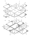
このPPシート1は、製箱しようとする箱の縦横高さ寸法に応じて適宜な縦横寸法で例えば略長方形にブランクカットされ、その面に加熱圧接による筋押し加工等により、井桁状に交差する二重折線2(第1の折線)を形成し、この折れ線2で区画された中央部を底板部3とし、その四周を短辺側および長辺側の側板部4,5としている。
【0017】
また、折線2によってPPシート1の四隅に区画され、対角位置にある側板4,5間の正方形の面に井桁の交点からPPシート1の各角部に向けて斜めの二重折線6(第2の折線)を筋押し加工等により形成し、この面を折線6を介して二つ折りされる略直角三角形状の重合片7としている。この重合片7の端部には正方形の切欠部7aが形成されているが、この機能については後述する。
【0018】
以上のPPシート1は薄くても軽量硬質なシート素材であるが、各折線2,6をいわゆるPPヒンジとして各部を容易に折曲げ可能となっている。
【0019】
また各折線2,6を二重としたのは、PPシート1の厚み分による折畳み時における融通性を考慮したためである。そして、その筋押し加工の加圧方向に応じて図1(b)に示すように、内側に向けて折曲げられるべく癖付けがなされる。
【0020】
この展開形状での平面加工時におけるPPシート1は四隅が切り欠かれているだけのため、派生材の発生量が少なく、シート素材そのものを有効利用できる。
【0021】
以上の癖付方向に応じて折線2をヒンジとして側板部4,5を立ち上げると、図2(a)に示すごとく、各側板部4,5はその端縁を接して底板部3より垂直に立上がり、上面開口の長方形の箱が形成され、この状態で重合片7は折線6をヒンジとし、この部分を斜辺として略直角三角形状に二つ折りされる。
【0022】
そして、長辺側の側板部5の裏面、すなわち製箱状態における表面中央には雄または雌の面ファスナー8aが溶着または接着などによりあらかじめ固定されている一方で、重合片7の長辺側側板部5との対向面には前記面ファスナー8aに噛合する面ファスナー8bが同じく溶着または接着などにより固定されている。
【0023】
これにより、図2(b)に示すように、各重合片7を長辺側側板部5に向けて折畳み、面ファスナー8a,8b同士を接合すれば、図2(c)に示すように、各重合片7は、元に戻ろうとする弾性復帰力に抗して長辺側側板部5の中央で突合わされた状態に固定され、上面が開口した箱10が完成する。
【0024】
なお、中央部で重合片7同士の重なりを防止し、突合わすために前記切欠部7aのカッティング長さが定まる。ただし、この切欠部7aは得ようとする箱の縦横寸法に応じて形成されるものであるため、側板部5の長さ寸法が高さ寸法に比べて十分長い場合には必ずしも必要ではない。
【0025】
図2(d)は完成した箱10における他の形態を示すものであり、この形態では、各重合片7がそれぞれ各側板部4,5に卍型の配列で固定されている。この場合には面ファスナー8a,8bを重合片7の先端と各側板部4,5の接合位置に応じてあらかじめ配置固定すればよい。このような形態とする場合にも、前記切欠部7aはなくてもよい。
【0026】
以上の箱10の完成状態における各側板部4,5の接合端縁同士は、重合片7の折込みによっても隙間が全く生じないため、これの内部に水などを満たしたとしても水漏れを生ずることがなく、他のパッキング手段を要することなく液密性に富んだ搬送容器として用いることができる。
【0027】
また、不要となった場合には、重合片7の面ファスナー8bを剥がすことにより、前記とは逆に平板状に展開することができるため、通い箱としての用途に好適である。
【0028】
なお、本実施形態では、折畳み展開可能とするために、重合片7の固定を雌雄の面ファスナー8a,8bによって展開可能としたが、展開する必要のない箱にあっては、製箱状態で固定するため、ステップル、クリップ、リベットなどの半永久的固定手段や接着手段などの永久固定手段を用いてもよいことも勿論であり、更にそれが箱を形成する樹脂、本例ではPP樹脂と同一のものを用いれば、箱が丸ごとリサイクル可能となる。
【0029】
図3〜図6は、本発明を保温箱ないしは保冷箱に適用した第二実施形態を示すものである。なお、本実施形態における前記実施形態と同一箇所には同一符号を援用し、異なる箇所、および新たに付加される箇所にのみ異なる符号を用いて説明する。
【0030】
まず、図3(a)において、PPシート1は基本的に前記実施形態と同様に、適宜な縦横寸法で略長方形にブランクカットされ、その面に筋押し加工により井桁状に交差する二重折線2を形成し、この折れ線2で囲われた中央を底板部3、その四隅を短辺側および長辺側の側板部4,5とし、さらに90度交差する側板4,5間の正方形の面には対角線状に斜めの二重折線6を筋押し加工により形成し、この面を折線6を介して二つ折りされる略直角三角形状の重合片7とし、その端部には正方形の切欠部7aを形成したものである。
【0031】
以上に加え、各側板部4,5の側縁には、一対の二重折線20を介してカバー片21,22が延長して設けられている。各カバー片21,22は、図3(b)に示すように、矩形状にカットされた側部断熱材23,24を包込むためのもので、折線20間の間隔は側部断熱材23,24の厚み寸法に対応させている。
【0032】
さらに、底板部3の上面にも、同一素材からなる底部断熱材25を接着するとともに、その上面にPPシート1と同一素材のカバー26を接着し、これを被覆している。
【0033】
各断熱材23,24,25を構成する素材としては、廃棄時における分別回収などの手数の省略を考慮して、比較的硬質な独立気泡性の発泡PPまたはPE(ポリエチレン)などが望ましく、また定寸もので単独では厚みが足りない場合には、複数層積層接着して用いることもできる。なお、各断熱材23,24,25の表面をカバー片21,22あるいはカバー26で被覆するのは後述する製箱状態における収納空間の内側を平滑化し、洗浄などを容易に行えるためである。カバー片21,22,26および後述するカバー33は、上記の如く設けることが望ましいが、仮に削除しても、断熱機能を持った箱の特性は有することから、耐久性や外観がさほど重要視されない場合や、コスト面で制限のある場合などには、これらのカバー(片)を設けなくてもよい。
【0034】
以上における底部断熱材25の縦横寸法は、底板部3の内側寸法とほぼ同一であり、長辺の側部断熱材24の寸法は長さが底面側断熱材25の寸法に等しく、高さ寸法は、側板部5の高さより底部断熱材+カバー26の厚み分を差引いた寸法としている。また、短辺の側部断熱材の幅寸法は、底部断熱材の幅寸法−2×(長辺の側面断熱材+カバー片22の厚み寸法)であり、高さ寸法は、側板部4の高さより底面部断熱材+カバー26の厚み分を差引いた寸法としている。いずれもこれらは製箱時における各断熱材の厚み寸法による相互干渉をさけるためであるが、これらの寸法は縦横の組合わせに応じて自由に設定できる。
【0035】
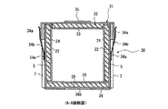
以上の各断熱材23.24,25の接着後は、前記第一実施形態と同様な折込み手順で製箱ができ、重合片7を面ファスナー8a,8bを介して固定した製箱完成状態では、図4に示すように、底部断熱材25の上部周縁に側部断熱材23,24が立設され、かつ短辺側側部断熱材23の両側が長辺側の側部断熱材24間に挟まれた状態でその内部を断熱空間とした上面開口の保温箱本体ないしは保冷箱本体30を得ることができる。
【0036】
この本体30の上面開口には蓋31が嵌めつけられる。蓋31は、図4を一瞥すれば明らかなように、前記PPシート1と同一素材に折線を形成し、これに沿って折込み接着して蓋形状に形成したものであり、その内側寸法は前記重合片7を含む本体30の外形寸法よりわずかに大きく形成されている。
【0037】
また、図4の一部に蓋31を反転して示すごとく、蓋31の内面には本体30の開口寸法と同一ないしこれよりわずかに小さい寸法の発泡PP製の上部断熱材32、およびこれの下面を覆うカバー33が一体的に接着され、閉蓋状態における開口面側の断熱性も確保している。
【0038】
これに加えて蓋31の長辺側両側面の中央には閉蓋状態を保持するための雄または雌の面ファスナー34aが熱融着または接着によって固定され、同じく本体30の長辺側外側面中央に配置された面ファスナー34aに対向している。
【0039】
蓋31の上面中央には段積み時における荷崩れ防止用の係合板35が接着されており、これに対向して本体30における底板部3の底面には係合板35を嵌め付けられる開口36aを形成した底板36が接着される。底板36および係合板35は、前記PPシート1と同一素材であって、底板36に開口36aを形成し、これによって抜かれた部分を係合板35として活用している。
【0040】
さらには、短辺側側板4の外側面にはバー状の把手37が接着される。この把手37は前記PPシート1の派生材などを有効利用することにより、前述する廃棄時の分別処理の手間を省力化している。
【0041】
図5,6は完成した保温箱または保冷箱を示すもので、本体30およびこれの上面を覆った蓋31に設けた固定側の面ファスナー34aにそれぞれ噛合するテープ状の面ファスナー34bにより本体30と蓋31とを連結している。そして、特に図6に示すように、収納空間はその6面とも断熱材23,24,25,32により囲われており、十分な断熱効果を得ることができるものとなる。
【0042】
そして、例えばこの箱内に収容される物品が食肉や魚類などの生鮮食料品の場合においては、長期保存により食料品から滲み出るドリップが本体30の内部に滲出することはさけられないが、前記第一実施形態と同じくこのような液体が外部に漏出することはなく、衛生的な保管および輸送が可能となる。
【0043】
また、通い箱として目的位置に搬送後、中身を受渡した後は展開できるので、内部に滲みだしたドリップなどを洗浄しやすく、かつ展開状態で持帰ることができるため、積荷空間が節約できると同時に、洗浄水の早期乾燥にも好適である。
【0044】
なお、本実施形態では本体30および蓋31の側面に面ファスナー34aを固定しておきこれらの間にテープ状面ファスナー34bで連結したが、テープ状面ファスナー34bの一端を蓋31の側面に固定し、本体30の側面に固定した面ファスナー34aに連結する構造とすることもできる。
【0045】
図7は以上の箱を段積み状態に積層保管した状態を示し、この場合には蓋31の上面に設けた係合板35が本体30底部の底板36に設けた開口36aにはまりこむため、安定して段積みすることが可能である。
【0046】
なお、以上の実施形態においても本体30を折畳み展開可能としているが、製箱状態を保存したままとしたい場合には前記実施形態と同様に、ステップル、クリップなどの半永久固定手段または接着などの永久固定手段により重合片7を側板に固定すればよい。
【0047】
また、本実施形態における係合板35、底板36、把手37などは必ずしも必須な部品でなく、必要に応じて付加すればよい。
【0048】
さらに各実施形態においては、箱を構成する樹脂シート素材としてPP製の二枚の基板間に同じくPP製の中空コア材をサンドイッチ状に一体成形した所定厚みのPPシートを用いたが、硬質発泡PP,またはPEなどを含む軽量硬質ポリオレフィン系シート素材一般を使用することができる。
【0049】
【発明の効果】
以上の説明により明らかなように、本発明による箱によれば、他の密封手段を要することなく製箱状態における液密性を保持できるようにし、かつ加工に際し派生材の発生が少ない。
また、本発明では簡単に製箱状態から展開できるようにし、通い箱としての用途に好適である。
さらに本発明にあっては液密性の高い箱を得ることができる。
【図面の簡単な説明】
【図1】(a),(b)は本発明の第一実施形態による箱の展開図および、立上げ過程を示す展開図である。
【図2】(a)〜(c)は立上げから、製箱完成までの過程を示す斜視図、(d)は製箱完成時における他の形態を示す斜視図である。
【図3】(a),(b)は本発明の第二実施形態による箱の展開図、および断熱材を付加した展開図である。
【図4】完成した箱本体と蓋その他の付加部品を示す分解斜視図である。
【図5】同箱本体に蓋をかぶせた状態の完成斜視図である。
【図6】図5のA−A線における断面図である。
【図7】複数の箱を段積みした状態を示す斜視図である。
【符号の説明】
1 PPシート
2 井桁状折線
3 底板部
4,5 側板部
6 折線
7 重合片
8a,8b 面ファスナー(固定手段)
10 箱
21,22 カバー片
23,24,25,32 断熱材
26,33 カバー
30 箱本体
31 蓋[0001]
TECHNICAL FIELD OF THE INVENTION
The present invention relates to a box formed by folding a single synthetic resin sheet into a box, and more particularly to a structure having a function of preventing liquid leakage to the outside in a box-making state.
[0002]
[Prior art]
The method of folding a single synthetic resin sheet into a box is well known, and the raw synthetic resin sheet is formed on the bottom plate and the left, right, front and rear side plates according to the length and width of the box to be boxed. Boxing is performed by forming a fold line at the boundary position by creasing and then raising the left, right, front and rear side plates from the periphery of the bottom plate along the fold line (for example, see Patent Document 1). .
[0003]
By the way, it is common to cut off the square part that occurs between the side plates that intersect at 90 degrees across the bottom plate part as a dead space by blank-cutting it, or leave it blank as a glue piece or a joint piece. It is a target.
[0004]
Furthermore, in the case of repeated use as a returnable box, the structure of the two side plates can be easily attached and detached, so that when not in use, it is developed into the original sheet shape and the transportation is easy. Has also been put to practical use.
[0005]
[Patent Document 1]
Utility Model Registration No. 3033627 [0006]
[Problems to be solved by the invention]
However, in such a conventional box, the material is wasted because the cut portion becomes a derived material in the processing. In addition, since a gap is formed at the joining position of the both side plates, for example, an article contained in a box becomes liquid by thawing or the like, or an article which produces liquid, such as meat, fish, etc. In the case of the fresh food product, there is a possibility that liquid leakage may occur from the joining position of the side plates to the outside. In order to keep the joining position liquid-tight, it is sufficient to cover this place with other sealing means, but for applications that can be folded and unfolded, the unfolding operation when returning to the original sheet shape is troublesome. There are issues.
[0007]
The present invention has been made to solve the above problems, and provides a box capable of maintaining liquid tightness in a box-making state without requiring other sealing means, and having less generation of a derivative material when processing a sheet. Is what you do.
Another object of the present invention is to provide a box suitable for use as a returnable box so that it can be easily deployed from a box-made state.
Still another object of the present invention is to provide a box for keeping cool with high liquid tightness.
[0008]
[Means for Solving the Problems]
In order to achieve the above object, the present invention relates to a synthetic resin sheet cut into an unfolded shape corresponding to the height and width of a box to be made, and folding along a folding line formed on the surface of the sheet. Wherein the sheet is continuous with both of the bottom plate located at the center thereof, four side plates continuous with the four peripheral portions of the bottom plate, and the adjacent side plates. An overlapped piece that can be folded so as to overlap the outer or inner part of the side plate portion, and the side plate portion is raised from the bottom plate portion using the fold line as a hinge, and any one of the side plate portions is folded by folding the overlapped piece. And fixing means for fixing the superposed piece to the side plate portion in a state of being superposed on the outer portion or the inner portion. According to the box of the present invention, there is no gap between the side plates at diagonal positions in a box-formed state, and a box with high liquid tightness can be obtained. Further, in the present invention, the processing is simple, and the amount of derivative material generated due to the processing is small. In addition, when it can be developed, there is an advantage that dirt can be easily washed and drying after washing can be performed in a short time.
[0009]
In the invention according to
[0010]
In the invention according to claim 3 of the present invention, the fixing means of the superposed piece comprises a superposed piece and a hook-and-loop fastener fixed to the side plate portion. It can be easily expanded to the original sheet by removing the hook-and-loop fastener from the state of the box, and conversely, the box can be made immediately from the sheet. And the volumetric efficiency is high. In the present invention, in place of the hook-and-loop fastener, a known engaging member having the same function, for example, a hook-shaped or button-shaped detachable engaging material or the like can be provided on the overlapped piece / side plate portion. If these members are selected to be the same as the resin forming the box, the entire box can be recycled.
[0011]
Further, as in the invention as set forth in
[0012]
In the invention according to
[0013]
In the invention according to
[0014]
In the invention according to
[0015]
BEST MODE FOR CARRYING OUT THE INVENTION
Hereinafter, preferred embodiments of the present invention will be described in detail with reference to the accompanying drawings.
1 and 2 show a first embodiment according to the present invention. In the present embodiment, a synthetic resin sheet for forming a box is provided between two substrates 1a made of polypropylene (hereinafter abbreviated as PP) as shown in an enlarged part of FIG. A PP corrugated cardboard sheet (hereinafter simply referred to as a PP sheet) 1 having a predetermined thickness formed by integrally molding a large number of PP
[0016]
This
[0017]
Further, the
[0018]
Although the
[0019]
The reason why each of the
[0020]
Since the
[0021]
When the
[0022]
A male or female hook-and-loop fastener 8a is previously fixed to the back surface of the long
[0023]
As a result, as shown in FIG. 2 (b), each
[0024]
In addition, the cutting length of the
[0025]
FIG. 2D shows another embodiment of the completed
[0026]
In the completed state of the
[0027]
Further, when it becomes unnecessary, by peeling off the hook-and-
[0028]
In this embodiment, in order to be able to be folded and unfolded, the fixing of the overlapping
[0029]
3 to 6 show a second embodiment in which the present invention is applied to a warm box or a cool box. In the present embodiment, the same reference numerals will be used for the same portions as those in the above-described embodiment, and different portions and only newly added portions will be described with different reference numerals.
[0030]
First, in FIG. 3 (a), the
[0031]
In addition to the above, cover
[0032]
Further, a bottom
[0033]
As a material constituting each of the
[0034]
The vertical and horizontal dimensions of the bottom
[0035]
After the above-mentioned heat insulating materials 23.24, 25 are bonded, a box can be formed by the same folding procedure as in the first embodiment, and in a box-finished state in which the overlapping
[0036]
A
[0037]
As shown in FIG. 4 in which the
[0038]
In addition, a male or female hook-and-
[0039]
At the center of the upper surface of the
[0040]
Further, a bar-shaped
[0041]
FIGS. 5 and 6 show the completed heat insulation box or cold insulation box. The
[0042]
Then, for example, in the case where the articles stored in the box are fresh foods such as meat and fish, drip oozing from the foods due to long-term storage is not escaping to the inside of the
[0043]
In addition, since it can be deployed after being transferred to the destination position as a returnable box and after delivering the contents, it is easy to clean drip etc. oozing inside and can be brought back in the deployed state, so that loading space can be saved. At the same time, it is also suitable for early drying of washing water.
[0044]
In the present embodiment, the hook-and-
[0045]
FIG. 7 shows a state in which the above-mentioned boxes are stacked and stored in a stacked state. In this case, the engaging
[0046]
In the above embodiment, the
[0047]
In addition, the
[0048]
Further, in each of the embodiments, a PP sheet having a predetermined thickness in which a PP hollow core material is integrally formed in a sandwich shape between two PP substrates is used as a resin sheet material constituting a box. A general lightweight rigid polyolefin-based sheet material including PP or PE can be used.
[0049]
【The invention's effect】
As apparent from the above description, according to the box of the present invention, it is possible to maintain the liquid tightness in the box-making state without requiring any other sealing means, and to reduce the generation of derived materials during processing.
Further, in the present invention, it is possible to easily develop the product from a box-making state, and it is suitable for use as a returnable box.
Further, according to the present invention, a highly liquid-tight box can be obtained.
[Brief description of the drawings]
FIGS. 1A and 1B are a development view of a box according to a first embodiment of the present invention and a development view showing a start-up process.
2 (a) to 2 (c) are perspective views showing a process from start-up to completion of box making, and FIG. 2 (d) is a perspective view showing another embodiment at the time of box making completion.
FIGS. 3A and 3B are a developed view of a box according to a second embodiment of the present invention and a developed view to which a heat insulating material is added.
FIG. 4 is an exploded perspective view showing a completed box main body, a lid and other additional parts.
FIG. 5 is a completed perspective view showing a state where the box body is covered with a lid.
6 is a sectional view taken along line AA of FIG.
FIG. 7 is a perspective view showing a state in which a plurality of boxes are stacked.
[Explanation of symbols]
DESCRIPTION OF
10
Claims (7)
前記シートは、その中央部に位置する底板部と、底板部の四周部に連続する4つの側板部と、隣接する側板部の双方に連続し且つ当該いずれかの側板部の外側部または内側部に重合するように折畳み可能な重合片と、
前記折線をヒンジとして前記側板部を底板部から立ち上げるとともに、前記重合片を折り畳むことによりいずれかの側板部の外側部または内側部に重合した状態で該重合片を側板部に固定する固定手段とを備えたことを特徴とする箱。A synthetic resin sheet cut into a developed shape according to the height and width of the box to be boxed, and a box formed by folding along a fold line formed on the surface of the sheet,
The seat is a bottom plate located at the center thereof, four side plates continuous with the four peripheral portions of the bottom plate, and an outer portion or an inner portion of any of the side plates connected to both adjacent side plates. A polymer piece that can be folded to polymerize into
Fixing means for raising the side plate portion from the bottom plate portion with the fold line as a hinge, and fixing the superposed piece to the side plate portion in a state where the superposed piece is folded and overlapped on the outer portion or the inner portion of one of the side plate portions. A box comprising:
前記側板部は底板部から第1の折線に沿って立ち上げられ、前記重合片は第1の折線及び第2の折線に沿って前記いずれかの側板部の外側部又は内側部に重合するように折り畳まれることを特徴とする請求項1に記載の箱。The fold lines are four first fold lines formed between the bottom plate portion and the side plate portion, and between the side plate portion and the overlapping piece, and the intersection of the first fold line and each corner of the sheet. And a second fold line formed obliquely on the polymer piece by connecting the
The side plate portion is raised from the bottom plate portion along a first fold line, and the overlapping piece overlaps with the outer portion or the inner portion of any one of the side plate portions along the first fold line and the second fold line. The box according to claim 1, wherein the box is folded.
Priority Applications (1)
| Application Number | Priority Date | Filing Date | Title |
|---|---|---|---|
| JP2002285425A JP2004123100A (en) | 2002-09-30 | 2002-09-30 | Box |
Applications Claiming Priority (1)
| Application Number | Priority Date | Filing Date | Title |
|---|---|---|---|
| JP2002285425A JP2004123100A (en) | 2002-09-30 | 2002-09-30 | Box |
Publications (1)
| Publication Number | Publication Date |
|---|---|
| JP2004123100A true JP2004123100A (en) | 2004-04-22 |
Family
ID=32278732
Family Applications (1)
| Application Number | Title | Priority Date | Filing Date |
|---|---|---|---|
| JP2002285425A Pending JP2004123100A (en) | 2002-09-30 | 2002-09-30 | Box |
Country Status (1)
| Country | Link |
|---|---|
| JP (1) | JP2004123100A (en) |
Cited By (15)
| Publication number | Priority date | Publication date | Assignee | Title |
|---|---|---|---|---|
| JP2013014378A (en) * | 2011-06-30 | 2013-01-24 | Daizo Kotaki | Plastic corrugated board container with frame and method for making the same |
| JP2014009732A (en) * | 2012-06-28 | 2014-01-20 | Fuji Electric Co Ltd | Heat insulation panel |
| CN104712885A (en) * | 2013-12-11 | 2015-06-17 | 富士电机株式会社 | Heat insulation board component |
| JP2019142552A (en) * | 2018-02-21 | 2019-08-29 | 凸版印刷株式会社 | Package container |
| JP2019142553A (en) * | 2018-02-21 | 2019-08-29 | 凸版印刷株式会社 | Packaging container |
| JP2019142551A (en) * | 2018-02-21 | 2019-08-29 | 凸版印刷株式会社 | Package container |
| JP2020026112A (en) * | 2018-08-16 | 2020-02-20 | 凸版印刷株式会社 | Method for manufacturing packaging container |
| KR102136639B1 (en) * | 2020-01-22 | 2020-07-22 | 쿠팡 주식회사 | Packaging box for cooling |
| KR20210007917A (en) * | 2019-07-12 | 2021-01-20 | 주식회사 에스랩아시아 | Box for maintaining freshness of shipment provided with insulator and the method for packing the box with the insulator |
| KR102226139B1 (en) * | 2020-07-01 | 2021-03-11 | 쿠팡 주식회사 | Packaging box for cooling |
| WO2021243478A1 (en) * | 2020-06-03 | 2021-12-09 | 三香科技股份有限公司 | Material box |
| KR102343126B1 (en) * | 2020-06-23 | 2021-12-28 | 주식회사 쓰리에스테크 | Folderable and reusable cool bag |
| JP2022010021A (en) * | 2017-07-25 | 2022-01-14 | 凸版印刷株式会社 | Packaging container |
| JP2022035905A (en) * | 2020-08-20 | 2022-03-04 | クーパン コーポレイション | Cold insulation packing box |
| JP7298360B2 (en) | 2019-07-23 | 2023-06-27 | 凸版印刷株式会社 | packaging container |
-
2002
- 2002-09-30 JP JP2002285425A patent/JP2004123100A/en active Pending
Cited By (29)
| Publication number | Priority date | Publication date | Assignee | Title |
|---|---|---|---|---|
| JP2013014378A (en) * | 2011-06-30 | 2013-01-24 | Daizo Kotaki | Plastic corrugated board container with frame and method for making the same |
| JP2014009732A (en) * | 2012-06-28 | 2014-01-20 | Fuji Electric Co Ltd | Heat insulation panel |
| CN104712885A (en) * | 2013-12-11 | 2015-06-17 | 富士电机株式会社 | Heat insulation board component |
| JP2022010021A (en) * | 2017-07-25 | 2022-01-14 | 凸版印刷株式会社 | Packaging container |
| JP7405125B2 (en) | 2017-07-25 | 2023-12-26 | Toppanホールディングス株式会社 | packaging container |
| JP7205061B2 (en) | 2018-02-21 | 2023-01-17 | 凸版印刷株式会社 | packaging container |
| JP2019142551A (en) * | 2018-02-21 | 2019-08-29 | 凸版印刷株式会社 | Package container |
| JP2019142553A (en) * | 2018-02-21 | 2019-08-29 | 凸版印刷株式会社 | Packaging container |
| JP7205063B2 (en) | 2018-02-21 | 2023-01-17 | 凸版印刷株式会社 | packaging container |
| JP2019142552A (en) * | 2018-02-21 | 2019-08-29 | 凸版印刷株式会社 | Package container |
| JP7205062B2 (en) | 2018-02-21 | 2023-01-17 | 凸版印刷株式会社 | packaging container |
| JP2020026112A (en) * | 2018-08-16 | 2020-02-20 | 凸版印刷株式会社 | Method for manufacturing packaging container |
| JP7135572B2 (en) | 2018-08-16 | 2022-09-13 | 凸版印刷株式会社 | Packaging container manufacturing method |
| KR20210007917A (en) * | 2019-07-12 | 2021-01-20 | 주식회사 에스랩아시아 | Box for maintaining freshness of shipment provided with insulator and the method for packing the box with the insulator |
| KR102311045B1 (en) | 2019-07-12 | 2021-10-08 | 주식회사 에스랩아시아 | Box for maintaining freshness of shipment provided with insulator and the method for packing the box with the insulator |
| JP7298360B2 (en) | 2019-07-23 | 2023-06-27 | 凸版印刷株式会社 | packaging container |
| KR102136639B1 (en) * | 2020-01-22 | 2020-07-22 | 쿠팡 주식회사 | Packaging box for cooling |
| US11273968B2 (en) | 2020-01-22 | 2022-03-15 | Coupang Corp. | Packaging box for cooling |
| JP2021116128A (en) * | 2020-01-22 | 2021-08-10 | クーパン コーポレイション | Packaging box for cooling |
| WO2021149886A1 (en) * | 2020-01-22 | 2021-07-29 | 쿠팡 주식회사 | Packaging cooler box |
| US11667454B2 (en) | 2020-01-22 | 2023-06-06 | Coupang Corp. | Packaging box for cooling |
| US10988300B1 (en) | 2020-01-22 | 2021-04-27 | Coupang Corp. | Packaging box for cooling |
| WO2021243478A1 (en) * | 2020-06-03 | 2021-12-09 | 三香科技股份有限公司 | Material box |
| KR102343126B1 (en) * | 2020-06-23 | 2021-12-28 | 주식회사 쓰리에스테크 | Folderable and reusable cool bag |
| KR102226139B1 (en) * | 2020-07-01 | 2021-03-11 | 쿠팡 주식회사 | Packaging box for cooling |
| JP2022035905A (en) * | 2020-08-20 | 2022-03-04 | クーパン コーポレイション | Cold insulation packing box |
| JP7071459B2 (en) | 2020-08-20 | 2022-05-19 | クーパン コーポレイション | Cold storage packaging box |
| US11639245B2 (en) | 2020-08-20 | 2023-05-02 | Coupang Corp. | Packaging box for cooling |
| TWI803794B (en) * | 2020-08-20 | 2023-06-01 | 韓商韓領有限公司 | Packaging box for cooling |
Similar Documents
| Publication | Publication Date | Title |
|---|---|---|
| JP2004123100A (en) | Box | |
| JP3784204B2 (en) | Method for producing a package formed of a flexible sheet | |
| JP3664607B2 (en) | Package manufacturing method and manufacturing apparatus | |
| TW202208245A (en) | Packaging box for cooling | |
| KR20230031484A (en) | Disposable Food Packaging Box | |
| JP2006213386A (en) | Delivery box | |
| JPH0741051A (en) | Shock-absorbing material and production thereof and container using the same | |
| CN208199105U (en) | Collapsible express delivery box | |
| JP2014094763A (en) | Food container | |
| JPH0449062Y2 (en) | ||
| JP7370105B1 (en) | food storage containers | |
| JP4708533B2 (en) | Packaging box | |
| JP2016222278A (en) | Covering type opening-closing box with cover | |
| JPH08133267A (en) | Corrugated cardboard box, corrugated cardboard therefor, corrugated-cardboard lid, and method for packing it | |
| JP3068877U (en) | Foldable container | |
| CN212501475U (en) | Box | |
| JP2000344227A (en) | Paper heat insulation and cold insulation case | |
| JPH031425Y2 (en) | ||
| JP2003237762A (en) | Packaging container and insulating packaging container using the same | |
| JP4149017B2 (en) | Manufacturing method of water-resistant and heat-insulated cardboard | |
| JPH0516089Y2 (en) | ||
| JP3247336B2 (en) | Tray paper container | |
| JP3078175U (en) | Paper square container | |
| KR20170131855A (en) | A Packing Box Having a Thick Inner Wall | |
| JP3047494U (en) | Assembled food packaging container |
Legal Events
| Date | Code | Title | Description |
|---|---|---|---|
| RD04 | Notification of resignation of power of attorney |
Free format text: JAPANESE INTERMEDIATE CODE: A7424 Effective date: 20040924 |