JP2004113770A - Analyte concentration determination apparatus and using method therefor - Google Patents
Analyte concentration determination apparatus and using method therefor Download PDFInfo
- Publication number
- JP2004113770A JP2004113770A JP2003125642A JP2003125642A JP2004113770A JP 2004113770 A JP2004113770 A JP 2004113770A JP 2003125642 A JP2003125642 A JP 2003125642A JP 2003125642 A JP2003125642 A JP 2003125642A JP 2004113770 A JP2004113770 A JP 2004113770A
- Authority
- JP
- Japan
- Prior art keywords
- sample
- tester
- skin
- analyte
- present
- Prior art date
- Legal status (The legal status is an assumption and is not a legal conclusion. Google has not performed a legal analysis and makes no representation as to the accuracy of the status listed.)
- Abandoned
Links
Images


Classifications
-
- A—HUMAN NECESSITIES
- A61—MEDICAL OR VETERINARY SCIENCE; HYGIENE
- A61B—DIAGNOSIS; SURGERY; IDENTIFICATION
- A61B5/00—Measuring for diagnostic purposes; Identification of persons
- A61B5/15—Devices for taking samples of blood
- A61B5/157—Devices characterised by integrated means for measuring characteristics of blood
-
- A—HUMAN NECESSITIES
- A61—MEDICAL OR VETERINARY SCIENCE; HYGIENE
- A61B—DIAGNOSIS; SURGERY; IDENTIFICATION
- A61B5/00—Measuring for diagnostic purposes; Identification of persons
- A61B5/15—Devices for taking samples of blood
- A61B5/150007—Details
- A61B5/150015—Source of blood
- A61B5/150022—Source of blood for capillary blood or interstitial fluid
-
- A—HUMAN NECESSITIES
- A61—MEDICAL OR VETERINARY SCIENCE; HYGIENE
- A61B—DIAGNOSIS; SURGERY; IDENTIFICATION
- A61B5/00—Measuring for diagnostic purposes; Identification of persons
- A61B5/15—Devices for taking samples of blood
- A61B5/150007—Details
- A61B5/150206—Construction or design features not otherwise provided for; manufacturing or production; packages; sterilisation of piercing element, piercing device or sampling device
- A61B5/150305—Packages specially adapted for piercing devices or blood sampling devices
-
- A—HUMAN NECESSITIES
- A61—MEDICAL OR VETERINARY SCIENCE; HYGIENE
- A61B—DIAGNOSIS; SURGERY; IDENTIFICATION
- A61B5/00—Measuring for diagnostic purposes; Identification of persons
- A61B5/15—Devices for taking samples of blood
- A61B5/150007—Details
- A61B5/150358—Strips for collecting blood, e.g. absorbent
-
- A—HUMAN NECESSITIES
- A61—MEDICAL OR VETERINARY SCIENCE; HYGIENE
- A61B—DIAGNOSIS; SURGERY; IDENTIFICATION
- A61B5/00—Measuring for diagnostic purposes; Identification of persons
- A61B5/15—Devices for taking samples of blood
- A61B5/150007—Details
- A61B5/150801—Means for facilitating use, e.g. by people with impaired vision; means for indicating when used correctly or incorrectly; means for alarming
- A61B5/150809—Means for facilitating use, e.g. by people with impaired vision; means for indicating when used correctly or incorrectly; means for alarming by audible feedback
-
- A—HUMAN NECESSITIES
- A61—MEDICAL OR VETERINARY SCIENCE; HYGIENE
- A61B—DIAGNOSIS; SURGERY; IDENTIFICATION
- A61B5/00—Measuring for diagnostic purposes; Identification of persons
- A61B5/15—Devices for taking samples of blood
- A61B5/150007—Details
- A61B5/150801—Means for facilitating use, e.g. by people with impaired vision; means for indicating when used correctly or incorrectly; means for alarming
- A61B5/150824—Means for facilitating use, e.g. by people with impaired vision; means for indicating when used correctly or incorrectly; means for alarming by visual feedback
-
- A—HUMAN NECESSITIES
- A61—MEDICAL OR VETERINARY SCIENCE; HYGIENE
- A61B—DIAGNOSIS; SURGERY; IDENTIFICATION
- A61B5/00—Measuring for diagnostic purposes; Identification of persons
- A61B5/15—Devices for taking samples of blood
- A61B5/151—Devices specially adapted for taking samples of capillary blood, e.g. by lancets, needles or blades
- A61B5/15101—Details
- A61B5/15126—Means for controlling the lancing movement, e.g. 2D- or 3D-shaped elements, tooth-shaped elements or sliding guides
- A61B5/15128—Means for controlling the lancing movement, e.g. 2D- or 3D-shaped elements, tooth-shaped elements or sliding guides comprising 2D- or 3D-shaped elements, e.g. cams, curved guide rails or threads
-
- A—HUMAN NECESSITIES
- A61—MEDICAL OR VETERINARY SCIENCE; HYGIENE
- A61B—DIAGNOSIS; SURGERY; IDENTIFICATION
- A61B5/00—Measuring for diagnostic purposes; Identification of persons
- A61B5/15—Devices for taking samples of blood
- A61B5/151—Devices specially adapted for taking samples of capillary blood, e.g. by lancets, needles or blades
- A61B5/15186—Devices loaded with a single lancet, i.e. a single lancet with or without a casing is loaded into a reusable drive device and then discarded after use; drive devices reloadable for multiple use
- A61B5/15188—Constructional features of reusable driving devices
- A61B5/1519—Constructional features of reusable driving devices comprising driving means, e.g. a spring, for propelling the piercing unit
-
- A—HUMAN NECESSITIES
- A61—MEDICAL OR VETERINARY SCIENCE; HYGIENE
- A61B—DIAGNOSIS; SURGERY; IDENTIFICATION
- A61B10/00—Other methods or instruments for diagnosis, e.g. instruments for taking a cell sample, for biopsy, for vaccination diagnosis; Sex determination; Ovulation-period determination; Throat striking implements
- A61B10/0045—Devices for taking samples of body liquids
- A61B2010/008—Interstitial fluid
-
- A—HUMAN NECESSITIES
- A61—MEDICAL OR VETERINARY SCIENCE; HYGIENE
- A61B—DIAGNOSIS; SURGERY; IDENTIFICATION
- A61B5/00—Measuring for diagnostic purposes; Identification of persons
- A61B5/15—Devices for taking samples of blood
- A61B5/151—Devices specially adapted for taking samples of capillary blood, e.g. by lancets, needles or blades
- A61B5/15101—Details
- A61B5/15115—Driving means for propelling the piercing element to pierce the skin, e.g. comprising mechanisms based on shape memory alloys, magnetism, solenoids, piezoelectric effect, biased elements, resilient elements, vacuum or compressed fluids
- A61B5/15117—Driving means for propelling the piercing element to pierce the skin, e.g. comprising mechanisms based on shape memory alloys, magnetism, solenoids, piezoelectric effect, biased elements, resilient elements, vacuum or compressed fluids comprising biased elements, resilient elements or a spring, e.g. a helical spring, leaf spring, or elastic strap
Landscapes
- Health & Medical Sciences (AREA)
- Life Sciences & Earth Sciences (AREA)
- Engineering & Computer Science (AREA)
- Molecular Biology (AREA)
- Animal Behavior & Ethology (AREA)
- Pathology (AREA)
- Physics & Mathematics (AREA)
- Biomedical Technology (AREA)
- Heart & Thoracic Surgery (AREA)
- Medical Informatics (AREA)
- Hematology (AREA)
- Surgery (AREA)
- Biophysics (AREA)
- General Health & Medical Sciences (AREA)
- Public Health (AREA)
- Veterinary Medicine (AREA)
- Diabetes (AREA)
- Manufacturing & Machinery (AREA)
- Measurement Of The Respiration, Hearing Ability, Form, And Blood Characteristics Of Living Organisms (AREA)
- Investigating Or Analysing Biological Materials (AREA)
- Investigating Or Analysing Materials By Optical Means (AREA)
- Investigating, Analyzing Materials By Fluorescence Or Luminescence (AREA)
Abstract
Description
【0001】
【発明の属する技術分野】
本発明の分野は、分析物の濃度決定装置である。
【0002】
【従来の技術】
生理学的なサンプルの分析物濃度決定は、今日の社会にとって重要性を増大している。このような分析評価は、臨床室の試験、家庭における試験等を含む種々の分野の用途で使用され、このような試験の結果は、種々の病状の診断及び管理で大きな役割を果たす。対象となる分析物は、糖尿病管理におけるブドウ糖、心臓血管の状態を監視するためのコレステロール、治療薬の水準を監視するための薬品、不法な水準の薬品等を認識することを含む。分析物の濃度決定の重要性が大きくなることに応答して、臨床及び家庭の試験の双方における種々の分析物濃度決定方法及び装置が開発された。
【0003】
生理学的なサンプルの分析物の濃度を決定する際に、最初に試験のための生理学的サンプルを得なければならない。しかしながら、サンプルを得て試験をすることは、煩わしく、複雑な手順を含む。不幸にも、分析物テスター、例えば、試験ストリップ、切開部材、測定器等のような複数の試験部材の有効な操作及び取り扱いは、例えば、ユーザの目視の敏感さ及び手の器用さに大きく依存し、これは、例えば、糖尿病の患者の場合、病状の進行で低下する。極端な場合、視野の著しい損失を有する人々にとって、ハンドアイ座標、指先の感覚、試験手順は著しく困難になり、補助装置又は人の追加的な補助を必要とする。
【0004】
試験ストリップ等のように形成されたテスターのような分析物テスターを使用することによって分析物の濃度の測定を行うための典型的な手順は、次の動作又はステップを含む(が、必ずしも所定の順序でなくともよい)。すなわち、(1)支持ケースから試験用品を取り出すステップと、(2)切開装置を把持し、切開装置装填キャップ又はドアを取り外すステップと、(3)切開装置から使用されたランセットを取り除き廃棄するステップと、(4)切開装置に新しいランセットを挿入するステップと、(5)ランセットから保護キャップをねじって外すステップと、(6)切開装置のキャップを交換するステップと、(7)切開装置を起こすステップと、(8)テスターのガラス瓶/容器を開けるステップと、(9)容器からテスターを取り除きテスターを測定器に挿入し、それを測定器に挿入するか、整合させるステップと、(10)切開装置を皮膚に対して保持するステップと、(11)切開装置を起動させるステップと、(12)皮膚から切開装置を取り除くステップと、(13)皮膚の切開領域からサンプルを抽出するステップと、(14)テスターにサンプルを供給し測定の結果を得るステップと、(15)テスターを廃棄するステップと、(16)試験場所を清浄にするステップと、(17)検査用品を支持ケースに戻すステップとを含む。もちろん、ある分析物測定装置及びプロトコルは、より少ないステップ又はより多いステップを含んでいてもよい。
【0005】
特に、ユーザの指先の感覚及び視覚が低下している場合において、動作の数を低減する1つの態様は、部品の汚れ及び/又はユーザのけがを引きおこすテスターや切開部品の取り扱いを最小限にするために複数の機能を組み合わせる集積装置を使用することである。この側面において、あるテスターディスペンサーは、テスターを連続的に収容し、作動時に連続的に前進させるように形成されている。この観点において、あるテスターディスペンサーは、作動時に連続したテスターを記憶し、前進させるために形成されている。試験ストリップを供給するこのような装置の例は、特許文献1、特許文献2、特許文献3、特許文献4、特許文献5、特許文献6、特許文献7及び特許文献8に開示されている。これらの試験ストリップ・ディスペンサーのいくつかは、生理学液な液体を試験するための測定器の機能性を含む。
【0006】
分析物の濃度決定評価に必要なステップの数を低減するために設計された他の分の分析装置は、自動又は半自動切開装置を含む。特許文献9は、ユーザが使用の前後に各ランセットを個々に取り外し交換する必要性をなくすために一回に、多数のランセットの連続した起動が可能なように形成された構造を開示する。しかしながら、この装置は、テスター部品又は機能性を含まない。
【0007】
分析物の濃度の決定評価過程を簡単にするために分析物濃度決定に含まれる種々の他の部品と切開型の装置を組み合わせる試みがなされてきた。例えば、特許文献10は、ばね機構に関連する単一の針、プッシャに関連する毛管及びテストストリップを含むサンプリング装置を開示している。また、分析器は、サンプルを分析するための装置に取り付けられてもよい。したがって、単一の針は、ばねを作動することによって次に他のばねで針を皮膚の表面に移動され後退されることによって、サンプルと連通する毛管を押すためにプッシャが移動され、プッシャが開放され、液体は、毛管を通して試験ストリップに移動される。
【0008】
特許文献11は、中空の針を有するベースと、膜を有するカバーとを有する装置を開示し、それによってベース及びカバーは、ヒンジ点で一緒に接続される装置が開示されている。閉鎖位置にあるとき、針は、膜と連通し、針を通って液体を引くことができ、カバーの膜に配置される。
【0009】
上述した装置及び技術の各々に関連したある欠点がある。例えば、前述した特許に開示された装置は、切開場所から離れた場所でサンプルを試験するように構成され、それによって切開場所から試験するための他の領域にサンプルを移動する必要がある。したがって、特許文献10の場合、サンプルは、毛管を通して試験ストリップに移動され、特許文献11の場合、サンプルは、針を通って膜に移動される。試験場所にサンプルを移動する間、このような方法及び装置を用いて搬送処理中に十分な量のサンプルが失われる。例えば、サンプルは、毛管、針等の側面に接着することがある。このようなサンプルの損失を補償するために、このような装置は、試験領域で正確な試験を実行するために切開場所から大量のサンプルを必要とし、しばしば、ユーザが必要な量のサンプルを抽出するために最初に切開した場所をしぼる必要があるか、他の場所を切開する必要がある。双方の選択は、糖尿病のユーザには困難であり、同様にそれらに関連して大きな痛みを伴う。
【0010】
しかしながら、多数の場合、ユーザは、不十分な量のサンプルがテスターと接触し、さらに追加のサンプルが適宜に供給することができないことに気づかない。このような場合において、不十分な量のサンプルが廃棄されるのでテスターが浪費され、新しいテスターで他の試験が実行されなければならないので、それによって分析物の濃度の決定のコストが増大する。
【0011】
このように、生理学的なサンプルの分析物の濃度の決定において使用される新しい装置及び方法の開発への関心が続いている。特別の関心は、テスターとサンプルが接触する前に、十分な量のサンプルがあるかどうかを効率よく、簡単な使用で決定することができ、正確な分析物の濃度の決定を実行するために最小限のサンプルの量を必要とする集積装置及びその使用方法の開発である。
【0012】
【特許文献1】
米国特許第5,510,266号公報
【特許文献2】
米国特許第5,560,266号公報
【特許文献3】
米国特許第5,575,403号公報
【特許文献4】
米国特許第5,736,103号公報
【特許文献5】
米国特許第5,757,666号公報
【特許文献6】
米国特許第5,797,693号公報
【特許文献7】
米国特許第5,856,195号公報
【特許文献8】
PCT国際公開WO 99/44508号公報
【特許文献9】
米国特許第6,228,100号公報
【特許文献10】
米国特許第6,099,484号
【特許文献11】
米国特許第5,820,570号公報
【0013】
【課題を解決するための手段】
生理学的なサンプルの分析物の濃度を決定するための装置及び方法が提供される。本発明の装置は、開口を有するハウジングと、前記ハウジング内に配置され中に保持されたランセットを有する切開部材と、前記ランセットを前記ハウジングの開口を通して移動させ皮膚の領域に切開部分を形成し前記皮膚の切開領域の表面に生理学的なサンプルを提供するために前記切開部材を作動させるための手段と、分析物の濃度の決定するために前記皮膚の切開領域の表面に十分な量の前記生理学的なサンプルが存在するかどうかを決定するための手段とを含むことを特徴とする測定器である。
【0014】
本発明の方法は、(1)皮膚の領域を切開して前記皮膚の領域に切開部分を提供し、前記皮膚の領域の表面に生理学的なサンプルを提供するステップと、(2)前記皮膚の表面に存在する前記生理学的なサンプルを照射するステップと、(3)前記皮膚の表面に存在する前記生理学的なサンプルから反射された光を検出するステップと、(4)前記検出された反射光に基づいて分析物の濃度の決定をするために十分な量の前記生理学的なサンプルが前記皮膚の表面に存在するかどうか決定するステップとを含む。十分な量のサンプルが存在することが決定されると、テスターがサンプルに接触され、サンプルの分析物の濃度が決定される。また、本発明は、本方法を実施する際に使用するキットを含む。
【0015】
【発明の実施の形態】
生理学的なサンプルの分析物の濃度を決定するための装置及び方法が提供される。本発明の装置は、開口を有するハウジングと、前記ハウジング内に配置され中に保持されたランセットを有する切開部材と、前記ランセットを前記ハウジングの開口を通して移動させ皮膚の領域に切開部分を形成し前記皮膚の切開領域の表面に生理学的なサンプルを提供するために前記切開部材を作動させるための手段と、分析物の濃度の決定するために前記皮膚の切開領域の表面に十分な量の前記生理学的なサンプルが存在するかどうかを決定するための手段とを含むことを特徴とする測定器である。
【0016】
本発明の方法は、(1)皮膚の領域を切開して前記皮膚の領域に切開部分を提供し、前記皮膚の領域の表面に生理学的なサンプルを提供するステップと、(2)前記皮膚の表面に存在する前記生理学的なサンプルを照射するステップと、(3)前記皮膚の表面に存在する前記生理学的なサンプルから反射された光を検出するステップと、(4)前記検出された反射光に基づいて分析物の濃度の決定をするために十分な量の前記生理学的なサンプルが前記皮膚の表面に存在するかどうか決定するステップとを含む。十分な量のサンプルが存在することが決定されると、テスターがサンプルに接触され、サンプルの分析物の濃度が決定される。また、本発明は、本方法を実施する際に使用するキットを含む。
【0017】
本発明を説明する前に、本発明は、特定の実施形態に制限されず、もちろん変化することを理解すべきである。また、この明細書で使用される用語は、特定の実施形態のみを説明することを目的としており、制限することを目的とするものではないことを理解すべきである。なぜならば、本発明の範囲は、添付した特許請求の範囲によってのみ制限されるからである。
【0018】
ある範囲の値が提供される場合、特に明確に述べない限り、その範囲の下限と上限との間で下限は、本発明の範囲内に包含され上述した単位の10倍までの干渉値、上述した範囲の他の状態又は干渉値が本発明内に包囲される。より小さい範囲に独立して含まれるこれらの小さい範囲の上限及び下限は、上述した範囲の特に排除的な制限を受ける。上述した範囲が一方又は双方の制限を含む場合、それらの含まれる制限の双方を含む範囲は、本発明内に含まれる。
【0019】
特に断らない限り、本明細書で使用されるすべての技術及び科学的用語は、本発明が属する技術分野の当業者によって一般に理解される意味と同じ意味を有する。本明細書で述べたと同じか、又はその等価的な方法及び材料が本発明の実施態様又は試験において使用されるが、好ましい方法及び材料を説明する。本明細書で述べたすべての刊行物は、引用される刊行物に関連して方法及び/又は材料を開示し、説明するために参照により本明細書に組み込まれる。
【0020】
本明細書で使用され、添付した特許請求の範囲において使用される、単一の形態の「a」及び「and」及び「the」は、特に断らない限り、複数の支持対象を含む。したがって、たとえば、テスター「a tester」への言及は、複数のこのようなテスターを含み、装置「the device」は、1つまたは複数の装置及び当業者に公知の等価物等を含む。
【0021】
本明細書で説明した刊行物は、本発明の出願日付の前に開示するために単独で提供されている。本発明が先発明のためにこれらの刊行物より先行しているという資格を有していないことを自認するものとして解釈されるものはない。さらに、提供された公開の日付は、独立して確認される必要がある実際の公開日とは異なるかもしれない。
【0022】
さらに、本発明を説明する際に、本装置がまず説明される。次に、本発明の方法の説明が行われ、本装置を含むキットの検証が行われる。
【0023】
装置
上述したように、生理学的なサンプルの分析物の濃度を決定するための装置が提供される。特に、皮膚の領域に切開部をつくり、正確な分析物の濃度の決定を行うために切開された領域の皮膚の表面に十分な量のサンプルが存在するかどうかを決定することができる分析物テスター測定器が提供される。このような装置を使用することは、十分な量のサンプルが存在する場合にのみ、ユーザが分析物の濃度に決定を実行し、テスターと不十分な量のサンプルとが接触することを防止することができるようにすることが有利である。したがって、本発明を使用することによって、不十分な量のサンプルがそれに添付されることによってテスターを廃棄するか、消費する必要性を解消し、分析物の濃度の決定のコストを低減する。
【0024】
本発明は、広範なテスターを使用して分析物濃度を決定するために適している。本装置が光学又は光度計タイプの装置であるので、本測定器ととともに使用されるテスターは、この技術分野で知られているような光学、比色形、又は光度計タイプ(互換的に使用される)のテスターとして正しく特徴を有する。このようなテスターは、広範な異なる分析物濃度の決定に使用され、この場合、代表的な分析物は、制限はされないが、ブドウ糖、コレステロール、乳酸塩、アルコール等を含む。多数の実施態様において、本発明とともに使用されるテスターは、生理学的なサンプル、例えば、間質性の液体、血液、血液フラクション、その成分等のブドウ糖の濃度を決定するために使用される。
【0025】
本発明をさらに説明すると、本発明の適切な基礎を提供するために、最初に代表的な比色分析テスターの検証が行われ、この場合のような検証は、例示であり、本発明の範囲を制限することは意図していない。要するに、制限はされないが、この明細書で説明した代表的な比色分析テスターを含む広範なテスターは、本発明とともに使用するために適していることは明らかである。適当なテスターの検証の後に本テスター測定器装置及び本方法の説明が行われる。最後に、本方法を実施する際に使用するためのキットの説明が行われる。
【0026】
代表的なテスター
同じ番号が同じ部品又は特徴部分を表す図面を参照すると、図1は、本発明のこれらの実施態様に使用される代表的な比色試薬テスター80を示す。テスター80は、一般に、少なくとも次の成分からつくられる。すなわち、サンプルを受けるマトリクス11、典型的に分析物酸化信号生成システム及び支持部材12の1つまたは複数の部材を含む試薬成分(構造的な部品としては図示しない)を含む。図1は、テストストリップとして形成されるように支持部材12の一端に接着剤13が配置されたマトリクス11を有するテスター80を示している図である。サンプルがマトリクス11の一方の側に入れられ、マトリクス11の反対側で反応を検出することができる穴14がマトリクス11の支持部材12に存在する。例示的な代表的なテスターの成分をさらに詳細に説明する。
【0027】
マトリクス
テスターに使用されるマトリクス11は不活性マトリクスであり、不活性マトリクスは、以下に説明するように信号生成システムの種々の部材、並びに、信号生成システム、すなわち、インジケータによって生成された光吸収性、又は発色性の生成物の支持を行う。マトリクス11は、生理学的なサンプル、例えば、血液を塗る場所、信号生成システムのインジケータによって生成された光吸収性生成物を検出する場所を提供するように形成されている。このように、マトリクス11は、それを通る水状の液体の流れを許可し、信号生成システムの化学反応を起こすための十分な空所スペースを提供するものである。種々の分析物検出の分析評価に使用される材料、寸法等において異なる多数の異なるマトリクスが開発され、代表的なマトリクスは、制限はされないが、米国特許第4,734,360号、同第4,900,666号、同第4,935,346号、同第5,059,394号、同第5,304,468号、同第5,306,623号、同第5,418,142号、同第5,426,032号、同第5,515,170号、同第5,526,120号、同第5,563,042号、同第5,620,863号、同第5,753,429号、同第5,573,452号、同第5,780,304号、同第5,789,255号、同第5,843,691号、同第5,846,486号、同第5,968,836号及び同第5,972,294号に開示されており、この内容は、参照により本明細書に組み込まれている。
【0028】
基本的には、マトリクス11の性質は、テスターにとっては重要ではなく、したがって、他の要素、例えばテスターを読むために使用される機器の性質、利便性等に関して選ばれる。このように、マトリクスの寸法及び有孔性は大きく変化し、ここでマトリクス11は、孔及び/又は有孔性勾配、例えば、サンプルを塗る領域、又はその近傍に大きな孔を有し、検出領域に小さい孔を有していてもよく、有していなくともよい。マトリクス11が製造される材料は多様であり、ポリマー、例えば、ポリスルフォン、ポリアミド、セルロース、又は吸収材紙等を含む。ここで材料は、信号生成システムの種々の部材と共有結合または非共有結合を与える機能を備えても備えなくてもよい。
【0029】
信号生成システム
マトリクス11に加えて、テスターはさらに、分析物の存在に応答して検出可能な物質を生成する信号生成システムの1つまたは複数の部材を含む。この検出可能な物質は、評価されたサンプルに存在する分析物の量を導き出すために使用することができる。このテスターにおいて、信号生成システムの1つまたは複数の部材は、マトリクスの少なくとも一部(すなわち、検出領域)に、多数の実施形態においては、マトリクスのほぼ全体に、例えば、共有結合または非共有結合によって結合されている。
【0030】
例えばブドウ糖が対象となる分析物である実施形態において、信号生成システムは、分析物酸化信号生成システムである。分析物酸化信号生成システムとは、サンプルの分析物の濃度が導き出される検出可能な信号を発生する際に、分析物が、1つまたは複数の適当な酵素によって酸化され、分析物の酸化物およびそれと一致または比例する量の過酸化水素を生成する。次に1つまたは複数のインジケータ成分から検出可能な生成物を生成するために過酸化水素が使用され、この場合、信号測定システムによって発生された検出可能な生成物の量、すなわち、信号は、初期サンプルの分析物の量に関連づけられる。また、このようにテスターに存在する分析物酸化信号生成システムは、過酸化水素をベースとした信号生成システムとして正しく特徴づけられる。
【0031】
上述したように、過酸化水素をベースとした信号生成システムは、分析物を酸化し、対応する過酸化水素の量を生成する酵素を含み、対応する量は、生成される過酸化水素の量がサンプルに存在する分析物の量に比例することを意味する。この第1の酵素の特定の性質は、評価される分析物の性質に依存するが、一般に酸化酵素である。このように、第1の酵素は、ブドウ糖酸化酵素(分析物がブドウ糖の場合)、コレステロール酸化酵素(分析物がコレステロールの場合)、アルコール酸化酵素(分析物がアルコールの場合)、乳酸塩酸化酵素(分析物が乳酸の場合)等である。対象となるこれら及び他の分析物と共に使用する他の酸化酵素は、当業者に知られており、また使用することもできる。試薬テスターがブドウ糖の濃度を検出するために設計されている場合、第1の酵素は、ブドウ糖酸化酵素である。ブドウ糖酸化酵素は、有利な供給源、例えば、アスペルギルス属ナイガー(niger)またはペニシリンのような自然に生じる供給源、又は、組み換えることにより生成される。
【0032】
信号生成システムの第2の酵素は、過酸化水素がある場合、検出可能な生成物に1つまたは複数のインジケータ成分の変換を起こす触媒であってもよく、この場合、反応によって生成される検出可能な生成物の量は、存在する過酸化水素の量に比例する。第2の酵素は、一般に、ペルオキシダーゼであり、この場合、適当なペルオキシダーゼは、ホースラディッシュ・ペルオキシダーゼ(HRP)、大豆・ペルオキシダーゼ、組み換えにより生成されるペルオキシダーゼ、ペルオキシダーゼのような作用を有する合成アナログ類等を含む(例えば、Y. Ci, F. Wang; Analytica Chimica Acta,233(1990年)、299頁乃至302頁参照)。
【0033】
インジケータ成分、例えば、基材は、過酸化水素が存在する場合過酸化水素によって形成されるか、分解され、所定の波長のレンジでの光を吸収するインジケータ染料を生成する。典型的には、インジケータ染料は、サンプル又は試薬が強力に吸収する波長と異なる波長を強力に吸収する。インジケータの酸化された形態は、色を有するか、又はかすかに着色されるか、又はマトリクスの色の変化を明らかにする無色の最終的な生成物であってもよい。すなわち、試験試薬は、漂白された色領域、又はこれとは別に、色のない領域に生じる色によってサンプル内のブドウ糖の存在を示すことができる。
【0034】
本発明に使用されるインジケータ成分は、1成分及び2成分の発色性の基剤を含む。1成分のシステムは、芳香族アミン類、芳香族アルコール類、アジン類及びテトラメチルベンジジン−HCLのようなベンジジン類を含む。適当な2成分のシステムは、1成分がMBTH、MBTH誘導体(例えば、参照により組込まれている米国特許第08/302,575号に開示されている誘導体参照)又は、4−アミノアンチピリンを含むが、他の成分は、芳香族アミン、芳香族アルコール、共役のアミン、共役のアルコール、芳香族アルデヒド、又は脂肪族アルデヒドである。例示的な2成分のシステムは、3−ジメチルアミノベンゼン酸(DMAB)と組み合わされた3−メチル−2−ベンゾチアゾリノン・ヒドラゾン・ヒドロクロライド(MBTH)、3,5−ジクロロ−2−ヒドロキシベンゼン−スルフォン酸(DCHBS)と組み合わせられたMBTH及び8−アニリノ−1ナフタレンスルフォン酸アンモニウム(ANS)と組み合わせられた3−メチル−2−ベンゾチアゾリノンヒドラゾンN−スルフォニルベンゼンスルフォネートモノナトリウム(MBTHSB)である。ある実施形態において、染料の対MBTHSB−ANSが好ましい。
【0035】
他の実施形態において、Kiyoshi Zaitsu, Yosuke Ohkura:「Horseradish Peroxidase」:「rapid and sensitiveassy forhydrogen peroxidateand the Peroxidase」に開示されている(Analytical Biochemistry(1980年)109,109頁乃至113頁参照)ような蛍光性検出可能な生成物(又は、例えば、蛍光性背景において検出可能な非蛍光性基剤)を生成する信号生成装置が使用される。
【0036】
支持部材
マトリクス11は、一般に支持部材12に取り付けられる。支持部材12は、望ましくない曲げ、よじれなしに測定器のような自動装置に挿入されるのに十分な剛性を有する材料から形成されることができる。マトリクス11は、有利な機構、例えば、クランプ、接着剤等によって支持部材12に取り付けられ、図面には接着剤13を使用して取り付けられていることが示されている。多数の実施形態において、支持部材12は、ポリオレフィン、例えば、ポリエチレン又はポリプロピレン、ポリスチレン、又はポリエステルのような材料から形成される。支持部材12の長さは、典型的には、テスターの長さか、又はそれに対応する長さである。
【0037】
上述したように、支持部材12は、測定器と共に使用されるか、測定器に挿入されることができるように形成されている。このように支持部材12、テスターは、種々の寸法、及び形状をとることができ、正確な寸法及び形状は、一部がテスターを使用する装置に依存する。
【0038】
このようなテスターを使用する際に、サンプルは、サンプルに存在する最初の量に比例する量で存在する検出可能な生成物を生成するために信号生成装置の部材と共に反応することができる。試験ストリップのマトリクス11に導入されるサンプルの量は、変化するが、5.0μl〜約10.0μlの範囲である。サンプルは、注入されるか、染みこむことができるようにするか、又は他の方法で導入される従来のプロトコルを用いてマトリクス11に導入されることができる。検出可能な精製物の量、すなわち、信号生成システムによって生成された信号が決定され、最初のサンプルの分析物の量に関連する。米国特許第4,734,360号、同第4,990,666号、同第4,935,346号、同第5,059,394号、同第5,304,468号、同第5,306,623号、同第5,418,142号、同第5,426,032号、同第5,515,170号、同第5,526,120号、同第5,563,042号、同第5,620,863号、同第5,753,429号、同第5,573,452号、同第5,780,304号、同第5,780,304号、同第5,789,255号、同第5,843,691号、同第5,846,486号、同第5,968,836号及び同第5,972,294号公報参照。これらの内容は、上述した反応、検出及び関連ステップの説明のために参照によりこの明細書に組み込まれる。
【0039】
本発明と共に使用されるために適当なこのような発色性の試薬テスターの例は、制限はされないが、米国特許第5,049,487号、同第5,563,042号、同第5,753,452号、同第5,789,255号に開示されたものを含み、これらの内容は、参照により組み込まれる。
【0040】
分析物濃度決定装置
上述したように、本発明は、上述したタイプのテスター等のようなテスターに供給される生理学的なサンプルの分析物の濃度を自動的に決定する。分析物濃度決定装置、すなわち、光測定器装置を含み、本装置の特徴は、正確な分析物濃度決定を実行するために切開場所がつくられる皮膚の場合、その表面に十分な量のサンプルがあるかどうかを決定することができることである。要するに、本発明の測定器は、サンプルがテスターと接触する前に十分なサンプルの寸法を決定し、それによって、十分な量のサンプルがある場合のみ、使用するためにテスターを維持する。本装置の多数の実施形態において、装置は、切開場所で十分な量のサンプルとテスターを接触させることができ、サンプルをテスターの場所に移動させるか、移動する必要性を解消する。この必要性は、移動部材への大きなサンプルの損失を招く。
【0041】
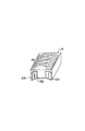
図2は、本装置の外観を示す斜視図である。したがって、装置2は、サンプル量の決定及び分析濃度の結果のような情報をユーザへ知らせるために外側に配置された表示部分6を有するハウジング4を含む。したがって、表示部分6は、種々のハードコピー及びソフトコピーの形態をとることができる。通常は、それは、液晶ディスプレィ(LCD)又は発光ダイオード(LED)ディスプレィのような目視ディスプレィであるが、テーププリンタ、聴覚信号等であってもよい。また、ハウジング4は、例えば、皮膚の領域に切開部をつくるためにランセットが突出することができるように、またサンプルを収集するために、また光が通過することができるようにハウジングの内側から外側に開口を提供するために壁又は側部を通って配置された開口8を有する。また、ハウジング4は、生理学的なサンプル推進部材10を含み、サンプル推進部材10は、以下に詳細に説明するように、典型的に開口8に隣接して配置され、以下に説明するように、開口8の周囲の少なくとも一部の周りに配置されたリングとして形成されている。また、ハウジング4は、例えば、ユーザがテスター及び/又は使い捨てランセットを装填し、及び/又は取り外すためにハウジング4の内側に接近するパネル又はカバー5を有する。同様に他のアクセス手段を使用できることは明らかである。パネル5は、適当な有利な手段によって閉鎖又は開放位置に可動なように形成されている。例えば、パネル5は、摺動可能に移動されるハウジング4等にヒンジにより取り付けられることができる。
【0042】
ハウジング4の形状は、種々の要因に依存して必要に応じて変化し、このような要因は、制限はされないが、それとともに使用されるテスターのタイプ及び寸法及び、例えば、カートリッジ又はケーシング等の測定器に収納されるこのようなテスターの数を含む。一般に、ハウジング4は、容易に及び快適に、例えば、人間工学的にユーザの手に保持される形状である。図2は、矩形の形状を有するハウジング4を示すが、同様に他の形状も可能である。例えば、ハウジング4は、正方形、円筒形、円形、板状、又は長円形等であってもよい。別の例として、ハウジング4の形状は、実質的に不規則な形状等のようなさらに複雑な形状であってもよい。
【0043】
また、ハウジング4の寸法は、それと共に使用されるテスターのタイプ及び寸法及び形状、ハウジング4等に保持され収容されるテスターの数のような種々の要因に依存する。一般に、ハウジング4は、容易に快適にユーザの手に保持され、容易に搬送可能である。
【0044】
ハウジング4は、種々の材料から製造され、このような材料は、分析物濃度決定に実質的に干渉せず、例えば、中に保持されたテスターの試薬と実質的に干渉しない。本ハウジングの製造に使用することができる代表的な材料は、制限はされないが、ポリテトラフルオロエチレン、ポリプロピレン、ポリエチレン、ポリスチレン、ポリカーボネート、及びその混合物のようなポリマー材料、ステンレススチール、アルミニウムのような金属、その合金、テフロン(登録商標)、珪質の材料、例えば、ガラス材料等を含む。
【0045】
図3は、装置2の概略図であり、さらに詳細には、ハウジングの内部部品を示している。図示するように、ハウジング4は、ランセットで切開される領域が開口8によって包囲されるように皮膚Sの領域に配置される。上述したように周囲の開口8は、切開される皮膚の領域で生理学的なサンプルの量を増大するように形成された任意選択的な生理学的サンプル推進部材10である。サンプル推進部材10は、切開すべき皮膚の領域を包囲するか、実質的に包囲し、包囲領域に圧力を加え、図示したように切開すべき隆起領域を提供することができるリング又は部分的なリングとして形成されることができる。このような態様において、生理学的な液体は、加圧領域から、加圧領域に隣接した領域、例えば、サンプル推進リング10の内側領域、すなわち、切開すべき領域及びサンプル推進リング10の外側の領域に移動し、生理学的な液体で切開される領域を充血させる。ユーザによって圧力が加えられ、例えば、ユーザは、皮膚に接触したとき、装置を押し下げるか、又は自動的に作動するようにすることができる。
【0046】
また、ハウジング2は、皮膚の領域に切開部をつくるために使い捨てのランセット21を保持し、テストのために生理学的なサンプルを提供するように構成された切開部材23を含み、この使い捨てランセットは、公知のものであり、さらに説明しない。このように使い捨てランセット21は、ハウジング4のボタンを手で押すか、測定器が皮膚の領域に接近して配置されるときに自動的に作動することができる。このようにランセット21は、皮膚から離れた第1の休止位置から開口8を通り皮膚に接触する第2の移動位置に移動され、ここでランセット21は、皮膚を貫通し、中に切開部を形成して試験のために切開場所から生理学的なサンプルを提供する。
【0047】
したがって、ランセット部材23は、ランセットで切開するために固定位置で使い捨てランセット21を保持するランセットホルダー23aと、皮膚に向かって使い捨てランセット21を移動するためのランセット移動機構23bとを有する。ランセットホルダー23aは、使い捨てランセット21が新しいランセットと交換するために、容易に取り外し可能か、又は放出可能であり、しかもランセットホルダー23aから意図しない動き又は放出を避けるために十分にしっかりと保持されるように、摩擦、スナップ嵌合等のような適当な手段を用いて使い捨てランセット21を保持する。ランセット移動機構23bは、ランセットを皮膚に向かって移動するための有利な機構を用いることができ、このような機構は当業者に公知である。ランセット移動機構23bは、例えば、いくつかの簡単なユーザの動作で自動的に又は手動で作動されることができる。例えば、動作は、ユーザが測定器のボタンを押すか、試験場所に測定器を単に押すと生じる。所望の動作を生じることができる測定器に関する限りでは、あるアクチュエータの設計及び製造は、当業者の水準で行われる。ある実施形態において、ランセット移動機構23bは、圧縮ばね機構等のようなばね機構である(例えば、米国特許第6,099,484号公報参照、この内容は参照によりここに組み込まれている)。しかしながら、他の適当なランセット機構を使用することができ、これらは技術分野でよく知られている。
【0048】
図示するように、使い捨てランセット21を備えた切開部材23は、使い捨てランセット21が皮膚Sから離れた第1の位置に配置されるように開口8に隣接して作動的に配置され、それによって、作動時に使い捨てランセット21が開口8を通して第2の位置に移動され、皮膚に接触し皮膚を切開する。この特定の実施形態において、切開部材23及び使い捨てランセット21は、開口8に対して所定の角度に配置されるが、切開部材23及び使い捨てランセット21は、開口8に対して適当な向きに配置されることは明らかである。
【0049】
また、ハウジング4は、少なくとも1つの光源16を含み、光源16から開口8の領域に光を集中することができる集光レンズ17を含む。光源16は、使い捨てランセット12によって切開された皮膚の領域に光を投射し、すなわち、それは、開口8によって包囲された皮膚の領域に光を投射する。また、光源16は、テスター、例えば、テスターに供給されたサンプルを有し、上述したようなサンプルのある分析物と反応する試薬を有するテスターのマトリクスに光を投射する。同じか、又は異なる光源が光をテスターに投射するとき皮膚に光を投射するようにしてもよく、この場合典型的には同じ光源が使用される。
【0050】
したがって、光源16は、典型的には発光ダイオード(LED)又は、レーザーダイオード、フィルタ付ランプ、フォトトランジスタ等のような他の従来の光源を含む。一般に、光源16は、2つ又はそれ以上、例えば3つのLED光源、又は2つ又はそれ以上の波長の光を放出することができる単一のダイオードを含む。光源16は、一般に、約400nm〜約1000nm、約500nm〜約940nmの範囲の波長の光を放出することができる。
【0051】
例えば、十分な量のサンプルが存在するかどうかを決定するために切開された皮膚の領域を照明するために、典型的には、光源16は、血液サンプルのヘモグロビンが、光を吸収する約400nm〜約1000nm、さらに一般的には、約480nm〜約600nmの波長の光を投射する。2つの明確な波長を使用する場合、分析物の濃度を決定するためにテスターを照明するにあたって、光源16は、約635nm及び約700nmの光を放出することができる。多くの実施態様において、光源は、約660nm及び940nmの光を放出することができ、ある実施態様において、光源は、約525nm、630nm及び940nmの光を放出することができる。本明細書で説明した波長は、例示を目的とし、本発明の範囲を制限するためのものではなく、多くの波長の他の組み合わせも可能であることは明らかである。上述した波長の光をつくる商業的に入手可能な光源は、この技術分野で公知であり、制限はされないが、ASRAM Opto Semiconductor, Inc.から販売されている635nm及び700nmの光を放出することができるLYSA676光源を含む。
【0052】
また、ハウジング4は、少なくとも1つの検出器20を含み、検出器20は、皮膚の表面に十分な量のサンプルが存在するかどうかを決定するために、反射光、すなわち、テスターに供給されるサンプルの分析物の濃度を決定するためにテスターのマトリクスのようなテスターからの反射光を受け、例えば拡散反射光を検出するために切開した皮膚の領域から反射した光、すなわち、反射光、例えば、拡散光を受ける。同じか、又は異なる検出器が上述した領域からの光を検出することができる。ハウジング4は、反射光を少なくとも1つの検出器20に入力するための光影像光学系25すなわち開口(図示せず)を含む。
【0053】
また、本発明は、切開が行われた皮膚の表面に十分な量及び容積のサンプルがあるかどうかを決定するための手段を含み、このような決定は、各領域から検出された反射光に基づいている。この手段は、デジタル集積回路24であり、このようなデジタル集積回路24は、ソフトウェアプログラムの制御下にあり、反射光が十分な量のサンプルを示すかを決定するためにそれに必要なステップ又は関数の全体を実行するように適切にプログラムされているか、そのような必要な機能を実行するハードウェア又はソフトウェアの組み合わせである。すなわち、サンプル量決定手段24は、皮膚の領域から、さらに詳細には生理学的なサンプルを有する皮膚の領域から検出された反射光に基づいて正確な分析物の濃度決定試験を実行するように十分な量のサンプルの量が存在するかどうかを決定するために測定器に記憶されたアルゴリズムを実行しそれに従うことができる。サンプル量決定手段24は、一般にアナログ信号を少なくとも1つの検出器20からデジタル信号に変換するアナログ/デジタル変換器22のような信号変換手段の出力を読み取る。したがって、サンプル量の決定手段24は、皮膚の領域から検出された反射光が、その領域に存在する十分な量のサンプルを示すかどうかを決定するために必要なステップの全てを実行することができる。
【0054】
正確な分析物濃度決定分析を実行するために十分な量のサンプルが存在するかどうかを決定する上述した手段に加えて、本発明の測定器は、このようなサンプル26が分析物の濃度決定のためのテスターに接触するサンプル26の分析物の濃度を決定するための手段を含む。すなわち、皮膚の表面に十分な量のサンプルが存在することが決定された場合、サンプルは、以下にさらに詳細に述べるように、分析物濃度決定のためにテスターと接触させられる。この手段は、一般にデジタル集積回路26であり、このようなデジタル集積回路26は、必要なステップ又は機能全体を実行するために適切にプログラムされているソフトウエアプログラムの制御の下にあり、このような必要な機能を実行するハードウエア又はソフトウエアの組み合わせである。すなわち、分析物決定手段26は、生理学的なサンプルの分析物の濃度を決定するために測定器に記憶されたアルゴリズムを実行しそれに従うことができる。(分析物濃度決定手段26は、サンプル評価手段24から分離した部品として図3に示されるが、ある実施態様において、皮膚の表面に十分な量のサンプルが存在するかどうかを決定する手段及び分析物の濃度を決定する手段は同じ集積回路であってもよい。)したがって、デジタル集積回路26は、生理学的なサンプルの分析物濃度を決定するために必要なステップの全体を実行することができる。
【0055】
また、本発明の測定器は、プログラム及びデータのメモリ28を含み、このデータ及びメモリ28は、データを記憶し、測定器の1つまたは複数のデジタル集積回路のデジタル集積回路の動作プログラムを実行することができる。また、本発明の測定器は、サンプルの寸法の十分な大きさ、分析物の濃度、エラーメッセージ等をユーザに知らせるために、上述したような表示装置を含む。
【0056】
上述したように、皮膚の表面領域に十分な量のサンプルが存在することが決定される場合、サンプルは、サンプルの分析物の濃度が決定されるようにテスターに接触される。したがって、上述したようなテスター又は以下に説明したタイプのテスターのような適当なテスターが、十分な量のサンプルに接触されるように配置される。テスターは、サンプルと接触するように手で配置されるか、サンプルに接触するように自動的に移動されて接触されることができる。したがって、本発明の測定器は、一般に、ハウジング4内、例えば、所定の領域又は凹所内に少なくとも1つのテスターを保持するための手段を含む。
【0057】
図3は、中に保持された複数のテスター90を有するテスターカートリッジ又はケーシング29の例示的な実施態様を示し、テスター90aは、適当な位置に移動されるように把持されることができる。
【0058】
図3に示す特定の実施形態において、テスターは、カートリッジ29から容易に把持されるように形成されている。図4は、本発明と共に使用されるのに適しているテスター90の例示的な実施態様の拡大図を示す。図示するように、テスター90は、信号生成装置(構造的な部材として図示しない)の部材を有するマトリクス99を含み、マトリクス99は支持体92に取り付けられる。支持体92は、上方に傾斜した端部92a及び端部92bを有し、多数の実施形態において、端部92a及び端部92bは、容易に把持するために、その中に把持穴9又は他の有利な手段を有する。多数の実施形態において、支持体92は、ウインドウ又は透明な領域等(図示せず)を有し、ウインドウ又は透明な領域等は、ウインドウ又は透明領域を通して光がマトリクス99を照射し、マトリクス99からの光を検出することができるようにマトリクス99上に配置される。このような態様において、テスター90は生理学的なサンプル上に配置され、マトリクスは、ウインドウ又は透明領域を通してマトリクスの反対側で読みとられる。このようなテスターは、図5に示すように、カートリッジ又はケースに収容するために積み重ねられることができ、図6のカートリッジ29に重ねられて示される。図6に示すように複数のテスター90がカートリッジ29内に保持され、テスター90aは、把持され、サンプルに接触するように移動されるために接近可能になるように配置される。このようなテスター形状及びカートリッジは、例示的なものであり、他のテスター構成及びこのようなテスターのカートリッジハウジングも当業者に明らかなように本発明ともに使用することができるので本発明の範囲を制限する意図はない。
【0059】
上述したように、テスターは、十分な量のサンプルが存在すると決定されたサンプルにテスターが接触するように移動される。このように、本発明の測定器は、テスター移動部材27を含む。テスターが従来の態様で移動され、この場合、次の実施態様は、例示として提供され、本発明の範囲を制限することを意図するものではない。このような実施態様において、テスターは、サンプルに接触するように移動され(すなわち、サンプルがテスターに接触するようには移動されない)、したがって、従来技術の装置においての場合のように、サンプルは、移動過程で失われない。サンプルと接触するとき、テスターの吸収マトリクスは、基本的にはその場所からサンプル全体を吸収する。このような態様において、多数の従来技術の装置においてより正確な分析物の濃度の測定のために皮膚の表面に少量のサンプルが存在することが必要になる。
【0060】
本発明において使用するために適しているテスター運動部材の例示的な実施態様が図7(A)〜図8(B)に示されている。移動部材47は、壁Wの溝40と摺動可能に係合するようにハウジング4の壁に関連している。カム部材42は、ピン45によって摺動可能な移動部材43の一方の側と関連している。この場合、テスター把持アーム46は、ピン48によって摺動可能な移動部材43の他方の側と関連している。
【0061】
図示したように、溝等である多数の実施形態において摺動可能な移動部材43は、バー41に沿って移動する。使用において、テスター移動部材43は、例えば、十分な量のサンプルが検出されたとき、手動または自動的に作動される。一般に、テスター移動部材43は、モーター等によって自動的に移動されるが、テスター移動部材43に作動的に関連するハウジング4の外面でボタン又はノブを摺動可能に移動させるユーザの動作によって手動によるようにしてもよい。テスター90aをカートリッジ29から生理学的なサンプルPSを有する皮膚Sの領域に移動させるためのテスターの移動ステップは、図7(A)〜図8(B)に示されている。次の図面において、把持アーム46は、テスター90aの無視できない図面を示すためにテスター90aと物理的には関連していない。把持アーム46はテスター90aを生理学的なサンプルを有する場所に移動させるためにテスター90aの穴によってテスター90aに関連していることは明らかである。
【0062】
図7(A)に示すように、カム部材42は、溝40の上部の第1の位置に配置され、カートリッジ29内にあるテスター90aに作動的に係合するが、テスター90aは、把持アーム46に接近可能である。カム部材42は、摺動可能な移動部材43がバー41に沿って移動可能であるので溝40に沿って摺動可能に移動する。摺動可能な移動部材43がバー41に沿って移動し、カム部材42が溝40に沿って摺動可能に移動すると、把持アーム46は、図7(A)〜図8(B)に示すように、生理学的なサンプルPSに向かう方向にテスター90aを移動させ、最終的に生理学的なサンプルの全体を吸収するためにマトリクス11が生理学的なサンプルPS上に配置されるように、摺動可能な移動部材が、第1の位置からほぼバー41の反対の端部の第2の位置にあるとき、生理学的なサンプルPSに接触するように配置される。把持アーム46は、生理学的なサンプルPSと接触するが、図8(B)に示すように分析物の濃度が、テスターが所定の位置にある間、分析物の濃度が決定されるように検出器20の視野又は少なくとも1つの光源16の通路を妨げないように形成されている。
【0063】
方法
テスターに加えられる生理学的なサンプルの分析物の濃度を決定するための方法が本発明によって提供される。さらに詳細には、分析物の濃度決定評価を実行するために皮膚の切開領域の表面に十分な量の生理学的なサンプルが存在するかどうかを決定し、十分な量のサンプルが存在するときにテスターがサンプルと接触し、サンプルの分析物の濃度を決定することができる方法が提供される。
【0064】
このように第1のステップは、皮膚の領域を切開し、テストのために皮膚の表面で生理学的なサンプルを提供することである。皮膚の適当な領域を切開することができるが、この場合、指、前肢、脚の指等を使用することができる。したがって、使い捨てランセット21を有する上述した装置は、ランセット21がハウジング4の開口8を通って突出し、皮膚に開口または切開部を提供するように、ランセット部材23を作動させ、ランセット21を皮膚に向かって移動させる。
【0065】
多数の実施形態において、サンプルは、その表現を促進することによって切開された場所に呈される。例えば、ランシングの前又は後で生理学的な液体が所望される対象領域を包囲する皮膚の領域に力が加えられる。このように、対象領域は、生理学的な液体で充血する。このような態様において、対象領域の周縁に力を加えないで提供されるよりも切開部分からより大量のサンプルが提供される。従って、上述したようなサンプル推進部材10は、その場所でサンプルを促進するために使用されることができる。
【0066】
生理学的な液体が皮膚の表面に存在するとき、サンプルは、光で照射される。例えば、サンプルは、約400nm〜約1000nm、通常、約480nm〜約600nm、さらに詳細には約525nmの光で照射することができるが、当業者によって明らかなように他の波長も可能である。本方法の1つの重要な特徴は、サンプルからの反射光の量に基づいてサンプルがテスターに接触する前に、サンプルの寸法が十分か不十分であることを決定することである。この態様において、テスターは、それに加えられるサンプルが不十分であることによって浪費されない。
【0067】
したがって、皮膚の表面でサンプルから光が反射され、この光が検出され、存在する生理学的なサンプルの量に関連される。例えば、皮膚は、525nmの光を反射するが、血液サンプルに存在するヘモグロビンは、525nmの光を吸収する。従って、十分な量のサンプルが存在する場合、十分な量の光がヘモグロビンによって吸収され、最小限の光が反射されるか、又はほとんどの光が反射されない。したがって、525nmの反射率が十分に低いか、所定の値等以下であるか、又は初期の測定値例えば、サンプルが存在する以前に、すなわち、血液が存在することなく反射された光の測定値から十分に低い場合、十分な量のサンプルが存在することが決定される。
【0068】
もし十分な量のサンプルが存在する場合には、上述したように、検出器に反射光を当てるために影像光学系又は開口を使用することができる。サンプルの量が十分であると決定されるサンプルの量は、対象となる分析物、テスター等のような種々の要因に依存して変化する。典型的には、約0.5μl〜約10μlの範囲の皮膚の表面のサンプルの量は、正確な分析物の測定を得るために十分であると決定される。
【0069】
したがって、不十分な量のサンプルが皮膚の表面に存在する場合には、分析物の濃縮は、サンプルの存在する量によっては実行されない。このような場合、ユーザは、例えば、現在の切開場所を絞るか、又はその場所を刺激することによって切開場所でサンプルを追加するように試みることができる。最初に、皮膚の表面に十分な量のサンプルが存在するか、又は上述したように最初に分析物の不十分性が決定された後、追加のサンプルが提供された場合、分析物のテスターが皮膚の表面で十分な量のサンプルと接触される。したがって、本発明の重要な特徴は、サンプルが、テスターの場所に移動されず、サンプルの場所にテスターが移動されるということである。この方法において、例えば、細管の場所から針等の場所への移動過程でサンプルが失われない。このように、正確な濃度の決定のために皮膚の表面に最小限の量のサンプルが必要になり、この場合、その量は、約0.5μl程である。特に、移動管等の補助なしにサンプルがテスターに直接吸収されるようにテスターがサンプルと接触される。
【0070】
本装置を使用するにあたって、テスターは、一般にテスター移動部材27を使用してサンプルに対して作動位置に移動される。例えば、上述したように、少なくとも1つのテスター、一般に複数のテスターが、ハウジング4の内側、典型的にはカートリッジ29内等に保持される。テスター移動部材27は、テスター90aがテスター移動部材27に接近可能であり、後に使用するために残りのカートリッジ29の内側に配置され、積み重ねられるように、カートリッジ29内に配置された最上のテスターすなわち、第1のテスター90aに係合し、この場合、テスター90aがカートリッジ29から移動されると、テスター90aの後に配置された次のテスターが把持される位置に移動される。このように、試験ストリップ移動部材27は、テスター90aを把持し、それを生理学的なサンプルと接触するように移動する(図7(A)〜図8(B)参照)。
【0071】
テスターがサンプルに接触すると、サンプルは、信号生成装置の部材と反応し、サンプルに存在する分析物の最初の量に比例した量で存在する検出可能な生成物を製造することができる。検出可能な生成物、すなわち、信号生成装置によって生じた信号は、決定され、最初のサンプルで分析物の量に関連される。本装置を使用するにあたって、サンプル26の分析物の濃度を決定するための手段は、上述したように分析物の濃度を決定し、分析物の濃度の決定の結果は、表示部材6によってユーザに報告される。
【0072】
キット
最後に、本発明を実施するキットが提供される。本発明のキットは、本発明による装置、光学測定器を含む。キットは、1つまたは複数のテスター、通常、上述したようなタイプのテスターのようなカートリッジ等に保持された1つまたは複数のテスター、一般に複数のテスターを含む。さらにキットは、1つまたは複数の使い捨てランセットを含む。さらに、キットは、標準溶液、例えば、ブドウ糖のような、濃度の分かっている分析物を含む標準溶液を有する。キットは、さらにテスターに供給される生理学的なサンプルの分析物の存在及び/又は濃度を決定するための装置を使用する説明書を含む。説明書は、紙又はプラスチック等のような基材に印刷されるようにしてもよい。したがって、説明書は、挿入される箱、キット又は、その部品の容器(すなわちパッケージ又はサブパッケージと関連した)のラベル等としてキットに存在するようにしてもよい。他の実施形態において、説明書は、適当な読み取り可能な記憶媒体、例えば、CD−ROMディスクに存在する電子記憶データファイルとして存在する。
上述した説明及び上述した議論から本発明は、分析物の濃度の決定するために十分な量のサンプルがあるかどうか、十分な量が存在すると決定されたサンプルの分析物の濃度を決定するための簡単で迅速で便利な方法を提供することは明らかである。上述した本発明は、制限はされないが、単一の手で持つ装置にいくつかの試験部品の統合、使用の容易性、最小限のサンプルを使用して、サンプルとテスターが接触する前に、十分な量のサンプルが存在するかどうかの決定及び正確な分析物の濃度の決定を含む多数の利点を提供する。このように、本発明は、技術に対して十分な寄与を行う。
【0073】
本発明は、最も実際的で好ましい実施形態と考えられるものを図示し、説明した。しかしながら、本発明は、本発明の範囲内で変更されることができ、この明細書を読んだときに当業者が明らかに変形を行うことは理解すべきである。
【0074】
特定の装置及び上述した方法は説明のためのものであり、制限を意図するものではない。関連した技術分野における当業者によって容易に行われるような開示された概念の意味及び等価物の範囲に有る変形例は、添付した特許請求の範囲内に含まれるものである。
【0075】
この発明の具体的な実施態様は次の通りである。
(1)前記ハウジング内に保持された少なくとも1つのテスターを含む請求項1に記載の装置。
(2)前記開口を通して前記十分な量のサンプルに接触するように前記少なくとも1つのテスターを移動させるように形成されたテスター移動部材を含む実施態様(1)に記載の装置。
(3)前記皮膚の切開領域の表面の前記生理学的なサンプルの量を増大するように形成された生理学的なサンプル推進部材を含む請求項1及び実施態様(1)又は(2)に記載の装置。
(4)前記生理学的なサンプルの分析物の濃度を決定するための手段を含む請求項1及び実施態様(1)〜実施態様(3)に記載の装置。
(5)前記方法は、請求項1及び実施態様(1)〜実施態様(4)に記載の装置を使用するステップを含む請求項2に記載の方法。
【0076】
(6)(a)実施態様(1)〜実施態様(4)に記載の少なくとも1つの装置と、(b)前記少なくとも1つの装置を使用するための命令を含む基板と、を含む少なくとも1つの試験ストリップを含み、一回で単一の試験ストリップを供給するためのキット。
(7)少なくとも1つのテスターを含む請求項3に記載のキット。
(8)(a)使い捨てランセットと、(b)標準溶液との少なくとも1つを含む請求項3又は実施態様(7)に記載のキット。
【0077】
【発明の効果】
本発明によれば、十分な量のサンプルがあるかどうかを効率よく、簡単な使用で決定することができ、正確な分析物の濃度の決定を実行するために最小限のサンプルの量を必要とする集積装置及びその使用方法を提供することができる。
【図面の簡単な説明】
【図1】図1は、試験ストリップとして形成された、本発明において使用されるのに適している代表的なテスターの例示的な実施態様を示す図である。
【図2】図2は、本装置の例示的な実施態様の斜視図である。
【図3】本装置の概略構成図である。
【図4】本発明とともに使用するのに適しているテスターの例示的な実施態様を示す図である。
【図5】一緒に積み重ねられた図4の複数のテスターを示す図である。
【図6】カートリッジ又はケーシングに保持された図5のテスターを示す図である。
【図7】図7(A)〜図7(D)は、皮膚の表面に存在する生理学的なサンプルに接触するテスターを移動させるテスター移動部材の例示的な実施態様のステップを示す図である。
【図8】図8(A)及び図8(B)は、皮膚の表面に存在する生理学的なサンプルに接触するテスターを移動させるテスター移動部材の例示的な実施態様のステップを示す図である。
【符号の説明】
2 装置
4 ハウジング
5 パネル
11 マトリクス
12 支持部材
13 接着剤
21 使い捨てランセット
23 切開部材[0001]
TECHNICAL FIELD OF THE INVENTION
The field of the invention is analyte concentration determination devices.
[0002]
[Prior art]
The determination of analyte concentrations in physiological samples is of increasing importance for today's society. Such assays are used in a variety of applications, including clinical laboratory tests, home tests, and the like, and the results of such tests play a significant role in the diagnosis and management of various medical conditions. Analytes of interest include recognizing glucose in diabetes management, cholesterol for monitoring cardiovascular conditions, drugs for monitoring therapeutic levels, illegal levels of drugs, and the like. In response to the growing importance of analyte concentration determination, a variety of analyte concentration determination methods and devices have been developed for both clinical and home testing.
[0003]
In determining the concentration of an analyte in a physiological sample, a physiological sample for testing must first be obtained. However, obtaining and testing a sample involves cumbersome and complicated procedures. Unfortunately, the effective manipulation and handling of multiple test components, such as analyte testers, e.g., test strips, dissectors, measuring instruments, etc., is highly dependent on, for example, the visual sensitivity of the user and dexterity of the hand. However, this decreases with the progression of the condition, for example in the case of diabetic patients. In extreme cases, hand-eye coordinates, fingertip sensation, test procedures become significantly more difficult for people with significant loss of vision and require additional equipment or additional human assistance.
[0004]
A typical procedure for measuring the concentration of an analyte by using an analyte tester, such as a tester formed, such as a test strip, includes the following operations or steps (although not necessarily a predetermined operation). The order does not have to be). That is, (1) removing the test article from the support case, (2) grasping the lancing device and removing the lancing device loading cap or door, and (3) removing and discarding the used lancet from the lancing device. (4) inserting a new lancet into the lancing device; (5) twisting off the protective cap from the lancet; (6) replacing the cap of the lancing device; and (7) raising the lancing device. (8) opening the vial / container of the tester; (9) removing the tester from the container and inserting the tester into the measuring instrument and inserting or aligning it into the measuring instrument; and (10) incision. Holding the device against the skin, (11) activating the lancing device, and (12) removing the lancing device from the skin. (13) extracting the sample from the incised area of the skin, (14) supplying the sample to the tester to obtain the measurement result, (15) discarding the tester, (16) Cleaning the test site; and (17) returning the test article to the support case. Of course, certain analyte measurement devices and protocols may include fewer or more steps.
[0005]
One aspect of reducing the number of movements, especially when the user's fingertip sensation and vision is diminished, is to minimize handling of testers and dissected parts that cause soiling of the part and / or injury to the user. For this purpose, an integrated device that combines a plurality of functions is used. In this aspect, some tester dispensers are configured to continuously receive and continuously advance the tester when activated. In this regard, certain tester dispensers are configured to store and advance a continuous tester when activated. Examples of such devices for supplying test strips are disclosed in U.S. Pat. Some of these test strip dispensers include the functionality of a meter for testing physiological fluids.
[0006]
Other analyzers designed to reduce the number of steps required for analyte concentration determination evaluation include automatic or semi-automatic lancing devices. U.S. Pat. No. 6,059,086 discloses a structure formed to enable continuous activation of multiple lancets at once to eliminate the need for the user to individually remove and replace each lancet before and after use. However, this device does not include tester components or functionality.
[0007]
Attempts have been made to combine incision-type devices with various other components involved in analyte concentration determination to simplify the evaluation process. For example, U.S. Pat. No. 6,037,064 discloses a sampling device that includes a single needle associated with a spring mechanism, a capillary associated with a pusher and a test strip. Also, the analyzer may be attached to a device for analyzing the sample. Thus, the single needle is moved by pushing the capillary in communication with the sample by actuating the spring and then moving the needle to the surface of the skin with the other spring and retracted, and the pusher is moved. Once released, the liquid is transferred to the test strip through the capillary.
[0008]
U.S. Pat. No. 6,037,056 discloses a device having a base with a hollow needle and a cover with a membrane, whereby the device is disclosed in which the base and the cover are connected together at a hinge point. When in the closed position, the needle is in communication with the membrane and can draw liquid through the needle and is located on the membrane of the cover.
[0009]
There are certain disadvantages associated with each of the devices and techniques described above. For example, the devices disclosed in the aforementioned patents are configured to test the sample at a location remote from the incision site, thereby requiring the sample to be moved from the incision site to another area for testing. Thus, in U.S. Pat. No. 6,037,086, the sample is transferred to the test strip through a capillary, and in U.S. Pat. While transferring the sample to the test site, a sufficient amount of sample is lost during the transfer process using such methods and apparatus. For example, the sample may adhere to the sides of capillaries, needles, and the like. To compensate for such sample loss, such devices require large volumes of sample from the incision site to perform accurate tests in the test area, often requiring the user to extract the required amount of sample. You need to squeeze the first incision or another incision. Both choices are difficult for diabetic users, and are also associated with great pain.
[0010]
However, in many cases, the user is unaware that an insufficient amount of sample has contacted the tester and that additional samples cannot be provided in a timely manner. In such cases, the tester is wasted because insufficient amounts of sample are discarded, and other tests must be performed with a new tester, thereby increasing the cost of determining the concentration of the analyte.
[0011]
Thus, there is a continuing interest in developing new devices and methods used in determining the concentration of an analyte in a physiological sample. Of special interest is the ability to determine with accurate and simple use whether there is a sufficient amount of sample before the sample comes into contact with the tester and to perform accurate analyte concentration determinations The development of integrated devices and methods of use that require a minimum sample volume.
[0012]
[Patent Document 1]
US Patent No. 5,510,266
[Patent Document 2]
US Patent No. 5,560,266
[Patent Document 3]
US Patent No. 5,575,403
[Patent Document 4]
U.S. Pat.No. 5,736,103
[Patent Document 5]
U.S. Pat. No. 5,757,666
[Patent Document 6]
U.S. Pat. No. 5,797,693
[Patent Document 7]
US Patent No. 5,856,195
[Patent Document 8]
PCT International Publication No. WO 99/44508
[Patent Document 9]
US Patent No. 6,228,100
[Patent Document 10]
U.S. Pat. No. 6,099,484
[Patent Document 11]
US Patent No. 5,820,570
[0013]
[Means for Solving the Problems]
Apparatus and methods are provided for determining the concentration of an analyte in a physiological sample. The apparatus of the present invention comprises a housing having an opening, an incision member having a lancet disposed within and held in the housing, and moving the lancet through an opening in the housing to form an incision in the area of the skin. Means for actuating the dissection member to provide a physiological sample to the surface of the skin incision area; and a sufficient amount of the physiological incision on the surface of the skin incision area to determine the concentration of an analyte. Means for determining whether a statistical sample is present.
[0014]
The method of the present invention comprises: (1) incising an area of skin to provide an incision in the area of skin and providing a physiological sample on a surface of the area of skin; Illuminating the physiological sample present on a surface; (3) detecting light reflected from the physiological sample present on the surface of the skin; and (4) detecting the reflected light. Determining whether a sufficient amount of the physiological sample is present on the surface of the skin to make a determination of the concentration of the analyte based on the Once it is determined that a sufficient amount of the sample is present, a tester is contacted with the sample and the analyte concentration of the sample is determined. The invention also includes kits for use in performing the method.
[0015]
BEST MODE FOR CARRYING OUT THE INVENTION
Apparatus and methods are provided for determining the concentration of an analyte in a physiological sample. The apparatus of the present invention comprises a housing having an opening, an incision member having a lancet disposed within and held in the housing, and moving the lancet through an opening in the housing to form an incision in the area of the skin. Means for actuating the dissection member to provide a physiological sample to the surface of the skin incision area; and a sufficient amount of the physiological incision on the surface of the skin incision area to determine the concentration of an analyte. Means for determining whether a statistical sample is present.
[0016]
The method of the present invention comprises: (1) incising an area of skin to provide an incision in the area of skin and providing a physiological sample on a surface of the area of skin; Illuminating the physiological sample present on a surface; (3) detecting light reflected from the physiological sample present on the surface of the skin; and (4) detecting the reflected light. Determining whether a sufficient amount of the physiological sample is present on the surface of the skin to make a determination of the concentration of the analyte based on the Once it is determined that a sufficient amount of the sample is present, a tester is contacted with the sample and the analyte concentration of the sample is determined. The invention also includes kits for use in performing the method.
[0017]
Before the present invention is described, it is to be understood that this invention is not limited to particular embodiments, which may, of course, vary. It is also to be understood that the terminology used in this specification is for the purpose of describing particular embodiments only, and is not intended to be limiting. This is because the scope of the present invention is limited only by the appended claims.
[0018]
Where a range of values is provided, unless stated otherwise, the lower limit between the lower and upper limits of that range is within the scope of the present invention and is limited to an interference value of up to 10 times the units described above, Other conditions or interference values in the specified range are encompassed within the present invention. The upper and lower limits of these smaller ranges, independently included in the smaller ranges, are subject to the particularly exclusive limitations of the ranges set forth above. Where the stated range includes one or both of the limits, ranges including both of those included limits are included in the invention.
[0019]
Unless defined otherwise, all technical and scientific terms used herein have the same meaning as commonly understood by one of ordinary skill in the art to which this invention belongs. Although the same or equivalent methods and materials described herein are used in the practice or testing of the present invention, the preferred methods and materials are now described. All publications mentioned herein are incorporated herein by reference to disclose and describe the methods and / or materials in connection with which the publications are cited.
[0020]
As used herein and in the appended claims, the singular forms "a" and "and" and "the" include plural referents unless the context clearly dictates otherwise. Thus, for example, reference to tester "a @ tester" includes a plurality of such testers, and device "the @ device" includes one or more devices and equivalents known to those skilled in the art.
[0021]
The publications discussed herein are provided solely for their disclosure prior to the filing date of the present application. Nothing is to be construed as an admission that the present invention is not entitled to antedate these publications by virtue of prior invention. Further, the dates of publication provided may be different from the actual publication dates which need to be independently confirmed.
[0022]
Further, in describing the present invention, the apparatus will be described first. Next, the method of the present invention will be described, and the kit including the device will be verified.
[0023]
apparatus
As described above, an apparatus is provided for determining the concentration of an analyte in a physiological sample. In particular, an analyte that can make an incision in the area of the skin and determine whether there is a sufficient amount of sample on the surface of the skin in the incised area to make an accurate analyte concentration determination A tester meter is provided. Using such a device prevents the user from making a determination on the concentration of the analyte only when a sufficient amount of sample is present, preventing contact between the tester and an insufficient amount of sample. It would be advantageous to be able to Thus, using the present invention eliminates the need to discard or consume the tester by attaching an insufficient amount of sample to it, reducing the cost of determining the concentration of the analyte.
[0024]
The present invention is suitable for determining analyte concentration using a wide range of testers. Because the device is an optical or photometer type device, the tester used with the meter may be of the optical, colorimetric, or photometer type (as used interchangeably) as known in the art. ) Is correctly characterized as a tester. Such testers are used to determine a wide variety of different analyte concentrations, where representative analytes include, without limitation, glucose, cholesterol, lactate, alcohol, and the like. In many embodiments, the tester used with the present invention is used to determine the concentration of glucose in a physiological sample, eg, interstitial fluid, blood, blood fractions, components thereof, and the like.
[0025]
To further illustrate the present invention, a verification of a representative colorimetric tester is first performed to provide a suitable basis for the present invention, and such verification is exemplary and the scope of the present invention Is not intended to be restricted. In short, it is clear that a wide range of testers, including but not limited to the representative colorimetric testers described herein, are suitable for use with the present invention. After verification of a suitable tester, a description of the tester measuring instrument apparatus and the method is provided. Finally, a kit is described for use in performing the method.
[0026]
Typical tester
Referring to the drawings, wherein like numbers represent like parts or features, FIG. 1 illustrates a representative
[0027]
Matrix
The
[0028]
Basically, the nature of the
[0029]
Signal generation system
In addition to the
[0030]
In embodiments where, for example, glucose is the analyte of interest, the signal generation system is an analyte oxidation signal generation system. An analyte oxidation signal generation system is a system in which an analyte is oxidized by one or more suitable enzymes in generating a detectable signal from which the concentration of the analyte in a sample is derived, and the analyte's oxide and Produces hydrogen peroxide in a proportionate or proportional amount. Hydrogen peroxide is then used to generate a detectable product from one or more indicator components, where the amount of detectable product generated by the signal measurement system, ie, the signal, is It is related to the amount of analyte in the initial sample. Also, the analyte oxidation signal generation system present in the tester is correctly characterized as a hydrogen peroxide based signal generation system.
[0031]
As described above, a hydrogen peroxide based signal generation system includes an enzyme that oxidizes an analyte and produces a corresponding amount of hydrogen peroxide, wherein the corresponding amount is the amount of hydrogen peroxide produced. Is proportional to the amount of analyte present in the sample. The particular properties of the first enzyme depend on the nature of the analyte being evaluated, but are generally oxidases. Thus, the first enzyme is glucose oxidase (if the analyte is glucose), cholesterol oxidase (if the analyte is cholesterol), alcohol oxidase (if the analyte is alcohol), lactate oxidase (When the analyte is lactic acid). Other oxidases for use with these and other analytes of interest are known and can be used by those skilled in the art. If the reagent tester is designed to detect glucose levels, the first enzyme is glucose oxidase. Glucose oxidase is produced by advantageous sources, for example, naturally occurring sources such as Aspergillus niger or penicillin, or by recombination.
[0032]
The second enzyme of the signal generation system may be a catalyst that causes the conversion of one or more indicator components to a detectable product in the presence of hydrogen peroxide, in which case the detection generated by the reaction The amount of possible product is proportional to the amount of hydrogen peroxide present. The second enzyme is generally a peroxidase, in which case suitable peroxidases include horseradish peroxidase (HRP), soybean peroxidase, recombinantly produced peroxidase, synthetic analogs having an action such as peroxidase, and the like. (For example, see Y. Ci, F. Wang; Analytical Chimica Acta, 233 (1990), pp. 299-302).
[0033]
The indicator component, eg, the substrate, is formed or decomposed by hydrogen peroxide in the presence of hydrogen peroxide to produce an indicator dye that absorbs light in a predetermined wavelength range. Typically, the indicator dye strongly absorbs at a different wavelength than the sample or reagent strongly absorbs. The oxidized form of the indicator may have a color or be faintly colored, or be a colorless end product that reveals a change in the color of the matrix. That is, the test reagent can indicate the presence of glucose in the sample by a color that occurs in a bleached color area or, alternatively, in an uncolored area.
[0034]
The indicator component used in the present invention contains a one-component and two-component color-forming base. One component systems include aromatic amines, aromatic alcohols, azines and benzidines such as tetramethylbenzidine-HCL. Suitable two-component systems include one in which MBTH, an MBTH derivative (see, for example, the derivatives disclosed in US Patent No. 08 / 302,575, incorporated by reference), or 4-aminoantipyrine. The other component is an aromatic amine, an aromatic alcohol, a conjugated amine, a conjugated alcohol, an aromatic aldehyde, or an aliphatic aldehyde. An exemplary two component system is 3-methyl-2-benzothiazolinone hydrazone hydrochloride (MBTH), 3,5-dichloro-2-hydroxy combined with 3-dimethylaminobenzene acid (DMAB). MBTH in combination with benzene-sulphonic acid (DCHBS) and 3-methyl-2-benzothiazolinone hydrazone N-sulfonylbenzenesulfonate monosodium in combination with ammonium 8-anilino-1 naphthalenesulfonate (ANS) ( MBTHSB). In certain embodiments, the dye pair MBTHSB-ANS is preferred.
[0035]
In other embodiments, see Kiyoshi Zaitzu, Yosuke Ohkuura: "Horserish Peroxidase": "rapid and sensitive assassin @ forhydogen @ peroxidate.com". A signal generator that produces a sex-detectable product (or, for example, a non-fluorescent base detectable in a fluorescent background) is used.
[0036]
Support member
The
[0037]
As described above, the
[0038]
In using such a tester, the sample can react with components of the signal generator to produce a detectable product present in an amount proportional to the initial amount present in the sample. The amount of sample introduced into the
[0039]
Examples of such chromogenic reagent testers suitable for use with the present invention include, but are not limited to, U.S. Patent Nos. 5,049,487; 5,563,042; Nos. 753,452 and 5,789,255, the contents of which are incorporated by reference.
[0040]
Analyte concentration determination device
As described above, the present invention automatically determines the analyte concentration of a physiological sample supplied to a tester, such as a tester of the type described above. It includes an analyte concentration determination device, i.e., a photometric device, which is characterized in that, in the case of skin where an incision is made to perform an accurate analyte concentration determination, a sufficient amount of sample is present on the surface. Is to be able to determine if there is. In essence, the meter of the present invention determines sufficient sample size before the sample comes into contact with the tester, thereby maintaining the tester for use only when there is a sufficient amount of sample. In many embodiments of the device, the device can contact the tester with a sufficient amount of sample at the incision location, eliminating or eliminating the need to move the sample to the tester location. This need results in large sample loss to the moving member.
[0041]
FIG. 2 is a perspective view showing the appearance of the present apparatus. Thus, the
[0042]
The shape of the housing 4 may vary as needed depending on various factors, such as, but not limited to, the type and size of the tester used therewith and, for example, the cartridge or casing. Includes the number of such testers stored in the meter. In general, the housing 4 is shaped to be easily and comfortably, for example ergonomically, held in the user's hand. FIG. 2 shows a housing 4 having a rectangular shape, but other shapes are possible as well. For example, the housing 4 may be square, cylindrical, circular, plate-like, oval, or the like. As another example, the shape of the housing 4 may be a more complex shape, such as a substantially irregular shape.
[0043]
The dimensions of the housing 4 also depend on various factors, such as the type and size and shape of the tester used with it, the number of testers held and contained in the housing 4 and the like. In general, the housing 4 is easily and comfortably held in the user's hand and is easily transportable.
[0044]
The housing 4 is manufactured from a variety of materials that do not substantially interfere with the analyte concentration determination, eg, do not substantially interfere with the reagents of the tester retained therein. Representative materials that can be used to make the housing include, but are not limited to, polymeric materials such as polytetrafluoroethylene, polypropylene, polyethylene, polystyrene, polycarbonate, and mixtures thereof, stainless steel, aluminum, and the like. Metals, alloys thereof, Teflon (registered trademark), siliceous materials, for example, glass materials and the like are included.
[0045]
FIG. 3 is a schematic diagram of the
[0046]
The
[0047]
Therefore, the
[0048]
As shown, the
[0049]
The housing 4 also includes at least one
[0050]
Accordingly,
[0051]
For example, to illuminate an area of the skin that has been cut to determine if a sufficient amount of sample is present, the
[0052]
The housing 4 also includes at least one
[0053]
The invention also includes a means for determining whether there is a sufficient amount and volume of the sample on the surface of the incised skin, such a determination being made based on the reflected light detected from each region. Based on. This means is a digital
[0054]
In addition to the means described above for determining whether a sufficient amount of a sample is present to perform an accurate analyte concentration determination analysis, the instrument of the present invention provides that such a
[0055]
The measuring instrument of the present invention also includes a program and
[0056]
As described above, if it is determined that a sufficient amount of the sample is present in the surface area of the skin, the sample is contacted with a tester such that the analyte concentration of the sample is determined. Accordingly, a suitable tester, such as a tester as described above or a tester of the type described below, is placed in contact with a sufficient amount of sample. The tester can be placed by hand to contact the sample, or automatically moved and contacted to contact the sample. Accordingly, the meter of the present invention generally includes means for holding at least one tester in the housing 4, for example, in a predetermined area or recess.
[0057]
FIG. 3 shows an exemplary embodiment of a tester cartridge or
[0058]
In the particular embodiment shown in FIG. 3, the tester is configured to be easily gripped from the
[0059]
As described above, the tester is moved such that the tester contacts a sample that has been determined to have a sufficient amount of sample. Thus, the measuring device of the present invention includes the
[0060]
An exemplary embodiment of a tester motion member suitable for use in the present invention is shown in FIGS. 7 (A) -8 (B). The moving
[0061]
As shown, the
[0062]
As shown in FIG. 7 (A), the
[0063]
Method
A method is provided by the present invention for determining the concentration of an analyte in a physiological sample that is added to a tester. More specifically, it is determined whether there is a sufficient amount of a physiological sample on the surface of the incision area of the skin to perform a concentration determination assessment of the analyte, and when a sufficient amount of the sample is present, A method is provided by which a tester can contact a sample and determine the concentration of an analyte in the sample.
[0064]
Thus, the first step is to incise an area of the skin and provide a physiological sample at the surface of the skin for testing. An appropriate area of skin can be incised, in which case fingers, forelimbs, toes, etc. can be used. Thus, the above-described device having a
[0065]
In many embodiments, the sample is presented at the incised location by facilitating its expression. For example, before or after lancing, a force is applied to the area of skin surrounding the target area where physiological fluid is desired. Thus, the region of interest is hyperemic with a physiological fluid. In such an embodiment, a larger volume of sample is provided from the incision than is provided without applying force to the periphery of the region of interest. Thus, the
[0066]
When a physiological fluid is present on the surface of the skin, the sample is illuminated with light. For example, the sample can be illuminated with light from about 400 nm to about 1000 nm, usually from about 480 nm to about 600 nm, and more particularly about 525 nm, although other wavelengths are possible as will be apparent to those skilled in the art. One important feature of the method is that it determines whether the size of the sample is sufficient or insufficient before the sample contacts the tester based on the amount of light reflected from the sample. In this embodiment, the tester is not wasted due to insufficient sample added to it.
[0067]
Thus, light is reflected from the sample at the surface of the skin, and this light is detected and related to the amount of physiological sample present. For example, the skin reflects light at 525 nm, while hemoglobin present in blood samples absorbs light at 525 nm. Thus, when a sufficient amount of sample is present, a sufficient amount of light is absorbed by hemoglobin and minimal or little light is reflected. Thus, the reflectivity at 525 nm is sufficiently low, less than or equal to a predetermined value, or an initial measurement, for example, a measurement of light reflected before the presence of the sample, ie, without the presence of blood. If is low enough, it is determined that a sufficient amount of sample is present.
[0068]
If a sufficient amount of sample is present, image optics or an aperture can be used to direct the reflected light to the detector, as described above. The amount of sample for which the amount of sample is determined to be sufficient will vary depending on various factors, such as the analyte of interest, the tester, etc. Typically, an amount of sample on the surface of the skin in the range of about 0.5 μl to about 10 μl is determined to be sufficient to obtain an accurate analyte measurement.
[0069]
Thus, if an insufficient amount of sample is present on the surface of the skin, analyte concentration will not be performed depending on the amount of sample present. In such a case, the user can attempt to add a sample at the incision location, for example, by squeezing the current incision location or stimulating that location. Initially, if a sufficient amount of sample is present on the surface of the skin, or if additional samples are provided after the initial analyte deficiency has been determined as described above, the analyte tester The skin surface is contacted with a sufficient amount of sample. Therefore, an important feature of the present invention is that the sample is not moved to the location of the tester, and the tester is moved to the location of the sample. In this way, for example, no sample is lost in the process of moving from a capillary location to a needle location. Thus, a minimum amount of sample is required on the surface of the skin for accurate concentration determination, in which case the amount is on the order of about 0.5 μl. In particular, the tester is contacted with the sample such that the sample is directly absorbed by the tester without the aid of a moving tube or the like.
[0070]
In using the present apparatus, the tester is generally moved to an operating position relative to the sample using a
[0071]
When the tester contacts the sample, the sample can react with the components of the signal generator to produce a detectable product present in an amount proportional to the initial amount of analyte present in the sample. The detectable product, ie, the signal generated by the signal generator, is determined and related to the amount of analyte in the initial sample. In using the present apparatus, the means for determining the concentration of the analyte in the
[0072]
kit
Finally, a kit for practicing the present invention is provided. The kit of the present invention comprises the device according to the present invention, an optical measuring instrument. The kit includes one or more testers, typically one or more testers, typically a plurality of testers, held in a cartridge or the like, such as a tester of the type described above. Further, the kit includes one or more disposable lancets. In addition, the kit has a standard solution, for example, a standard solution containing an analyte of known concentration, such as glucose. The kit further includes instructions for using the device for determining the presence and / or concentration of an analyte in a physiological sample supplied to the tester. The instructions may be printed on a substrate such as paper or plastic. Accordingly, the instructions may be present in the kit, such as on a box or kit to be inserted or a label on a container (ie, associated with the package or subpackage) of the component. In other embodiments, the instructions are present as an electronically stored data file residing on a suitable readable storage medium, for example, a CD-ROM disc.
From the above description and the above discussion, the present invention is directed to determining whether there is a sufficient amount of a sample to determine the concentration of an analyte, and determining the concentration of the analyte in a sample determined to be present in a sufficient amount. Obviously, it provides a simple, fast and convenient way of doing so. The invention described above, without limitation, integrates several test parts into a single hand-held device, ease of use, and uses a minimum of sample, before contact between the sample and the tester. It offers a number of advantages including determining whether a sufficient amount of sample is present and determining the exact analyte concentration. Thus, the present invention makes a significant contribution to the technology.
[0073]
The present invention has been shown and described in what is considered to be the most practical and preferred embodiment. However, it should be understood that the invention can be varied within the scope of the invention, and that a person skilled in the art, upon reading this specification, will make obvious variations.
[0074]
The specific devices and methods described above are illustrative and not intended to be limiting. Modifications that fall within the meaning and equivalents of the disclosed concepts as readily accomplished by one of ordinary skill in the relevant art are intended to be within the scope of the appended claims.
[0075]
Specific embodiments of the present invention are as follows.
The apparatus of claim 1, comprising (1) at least one tester held within the housing.
The apparatus of claim 1, further comprising: a tester moving member configured to move the at least one tester through the opening to contact the sufficient amount of sample.
3. The method according to claim 1 and embodiment (1) or (2), further comprising a physiological sample propulsion member configured to increase an amount of the physiological sample on the surface of the skin incision area. apparatus.
4. The device according to claim 1 and embodiments (1) to (3), comprising (4) means for determining the concentration of an analyte in the physiological sample.
(5) The method according to
[0076]
(6) at least one device comprising: (a) at least one device according to embodiments (1) to (4); and (b) a substrate comprising instructions for using said at least one device. Kit for supplying a single test strip at a time, including test strips.
(7) The kit according to claim 3, comprising at least one tester.
The kit according to claim 3 or embodiment (7), comprising at least one of (8) (a) a disposable lancet and (b) a standard solution.
[0077]
【The invention's effect】
According to the present invention, it is possible to efficiently and easily determine whether there is a sufficient amount of sample and require a minimum amount of sample to perform an accurate analyte concentration determination. And a method of using the same.
[Brief description of the drawings]
FIG. 1 illustrates an exemplary embodiment of a representative tester formed as a test strip and suitable for use in the present invention.
FIG. 2 is a perspective view of an exemplary embodiment of the device.
FIG. 3 is a schematic configuration diagram of the present apparatus.
FIG. 4 illustrates an exemplary embodiment of a tester suitable for use with the present invention.
FIG. 5 shows the plurality of testers of FIG. 4 stacked together.
FIG. 6 shows the tester of FIG. 5 held on a cartridge or casing.
FIGS. 7A-7D illustrate steps of an exemplary embodiment of a tester moving member for moving a tester in contact with a physiological sample present on the surface of the skin. .
8 (A) and 8 (B) show steps of an exemplary embodiment of a tester moving member for moving a tester in contact with a physiological sample present on the surface of the skin. .
[Explanation of symbols]
2 device
4 housing
5mm panel
11 matrix
12 support member
13 adhesive
21 disposable lancet
23 incision member
Claims (3)
(b)前記ハウジング内に配置され中に保持されたランセットを有する切開部材と、
(c)前記ランセットを前記開口を通して移動させ皮膚の領域に切開部分を形成し前記皮膚の切開領域の表面に生理学的なサンプルを提供するために前記切開部材を作動させるための手段と、
(d)分析物の濃度を決定するために前記皮膚の切開領域の表面に十分な量の前記生理学的なサンプルが存在するかどうかを決定するための手段と、を含む、生理学的なサンプルの分析物の濃度を決定するための装置。(A) a housing having an opening;
(B) a dissecting member having a lancet disposed within and retained within the housing;
(C) means for moving the lancet through the opening to form an incision in an area of skin and actuating the incision member to provide a physiological sample to a surface of the incision area of the skin;
(D) means for determining whether a sufficient amount of said physiological sample is present at the surface of the incision area of said skin to determine the concentration of the analyte. A device for determining the concentration of an analyte.
(b)前記皮膚の表面に存在する前記生理学的なサンプルを照射するステップと、
(c)前記皮膚の表面に存在する前記生理学的なサンプルから反射された光を検出するステップと、
(d)前記検出された反射光に基づいて分析物の濃度の決定のために十分な量の前記生理学的なサンプルが前記皮膚の表面に存在するかどうか決定するステップと、を含む生理学的なサンプルの分析物の濃度を決定する方法。(A) incising an area of skin to provide an incision in the area of skin and providing a physiological sample to the surface of the skin;
(B) irradiating the physiological sample present on the surface of the skin;
(C) detecting light reflected from the physiological sample present on the surface of the skin;
(D) determining whether a sufficient amount of the physiological sample is present on the surface of the skin for determination of an analyte concentration based on the detected reflected light. A method for determining the concentration of an analyte in a sample.
(b)前記少なくとも1つの装置を使用するための説明書を含む基板と、を含む少なくとも1つの試験ストリップを含み、一回で単一の試験ストリップを供給するためのキット。(A) at least one device according to claim 1,
(B) a kit for supplying a single test strip at a time, comprising at least one test strip comprising: a substrate comprising instructions for using said at least one device;
Applications Claiming Priority (1)
| Application Number | Priority Date | Filing Date | Title |
|---|---|---|---|
| US10/137,598 US6945943B2 (en) | 2002-05-01 | 2002-05-01 | Analyte concentration determination devices and methods of using the same |
Publications (1)
| Publication Number | Publication Date |
|---|---|
| JP2004113770A true JP2004113770A (en) | 2004-04-15 |
Family
ID=29215701
Family Applications (1)
| Application Number | Title | Priority Date | Filing Date |
|---|---|---|---|
| JP2003125642A Abandoned JP2004113770A (en) | 2002-05-01 | 2003-04-30 | Analyte concentration determination apparatus and using method therefor |
Country Status (11)
| Country | Link |
|---|---|
| US (1) | US6945943B2 (en) |
| EP (1) | EP1359418B1 (en) |
| JP (1) | JP2004113770A (en) |
| CN (1) | CN1455258A (en) |
| AT (1) | ATE369560T1 (en) |
| CA (1) | CA2427092A1 (en) |
| DE (1) | DE60315373T2 (en) |
| HK (1) | HK1057254A1 (en) |
| IL (1) | IL155349A0 (en) |
| SG (1) | SG108916A1 (en) |
| TW (1) | TW200403040A (en) |
Cited By (2)
| Publication number | Priority date | Publication date | Assignee | Title |
|---|---|---|---|---|
| JP2014530052A (en) * | 2011-09-22 | 2014-11-17 | サノフィ−アベンティス・ドイチュラント・ゲゼルシャフト・ミット・ベシュレンクテル・ハフツング | Blood sample detection |
| JP2023078299A (en) * | 2017-01-10 | 2023-06-06 | ドローブリッジ ヘルス,インコーポレイテッド | Devices, systems, and methods for sample collection |
Families Citing this family (82)
| Publication number | Priority date | Publication date | Assignee | Title |
|---|---|---|---|---|
| US7828749B2 (en) | 1996-05-17 | 2010-11-09 | Roche Diagnostics Operations, Inc. | Blood and interstitial fluid sampling device |
| US20020010406A1 (en) | 1996-05-17 | 2002-01-24 | Douglas Joel S. | Methods and apparatus for expressing body fluid from an incision |
| US7235056B2 (en) | 1996-05-17 | 2007-06-26 | Amira Medical | Body fluid sampling device and methods of use |
| EP1579814A3 (en) | 1996-05-17 | 2006-06-14 | Roche Diagnostics Operations, Inc. | Methods and apparatus for sampling and analyzing body fluid |
| US6036924A (en) | 1997-12-04 | 2000-03-14 | Hewlett-Packard Company | Cassette of lancet cartridges for sampling blood |
| US6391005B1 (en) | 1998-03-30 | 2002-05-21 | Agilent Technologies, Inc. | Apparatus and method for penetration with shaft having a sensor for sensing penetration depth |
| US8641644B2 (en) | 2000-11-21 | 2014-02-04 | Sanofi-Aventis Deutschland Gmbh | Blood testing apparatus having a rotatable cartridge with multiple lancing elements and testing means |
| US7025774B2 (en) | 2001-06-12 | 2006-04-11 | Pelikan Technologies, Inc. | Tissue penetration device |
| EP1404234B1 (en) | 2001-06-12 | 2011-02-09 | Pelikan Technologies Inc. | Apparatus for improving success rate of blood yield from a fingerstick |
| US9795747B2 (en) | 2010-06-02 | 2017-10-24 | Sanofi-Aventis Deutschland Gmbh | Methods and apparatus for lancet actuation |
| DE60238119D1 (en) | 2001-06-12 | 2010-12-09 | Pelikan Technologies Inc | ELECTRIC ACTUATOR ELEMENT FOR A LANZETTE |
| JP4272051B2 (en) | 2001-06-12 | 2009-06-03 | ペリカン テクノロジーズ インコーポレイテッド | Blood sampling apparatus and method |
| US9427532B2 (en) | 2001-06-12 | 2016-08-30 | Sanofi-Aventis Deutschland Gmbh | Tissue penetration device |
| ES2336081T3 (en) | 2001-06-12 | 2010-04-08 | Pelikan Technologies Inc. | SELF-OPTIMIZATION PUNCTURE DEVICE WITH MEANS OF ADAPTATION TO TEMPORARY VARIATIONS IN CUTANEOUS PROPERTIES. |
| US7981056B2 (en) | 2002-04-19 | 2011-07-19 | Pelikan Technologies, Inc. | Methods and apparatus for lancet actuation |
| WO2002100254A2 (en) | 2001-06-12 | 2002-12-19 | Pelikan Technologies, Inc. | Method and apparatus for lancet launching device integrated onto a blood-sampling cartridge |
| US9226699B2 (en) | 2002-04-19 | 2016-01-05 | Sanofi-Aventis Deutschland Gmbh | Body fluid sampling module with a continuous compression tissue interface surface |
| US8337419B2 (en) | 2002-04-19 | 2012-12-25 | Sanofi-Aventis Deutschland Gmbh | Tissue penetration device |
| US7371247B2 (en) | 2002-04-19 | 2008-05-13 | Pelikan Technologies, Inc | Method and apparatus for penetrating tissue |
| US8372016B2 (en) | 2002-04-19 | 2013-02-12 | Sanofi-Aventis Deutschland Gmbh | Method and apparatus for body fluid sampling and analyte sensing |
| US7976476B2 (en) | 2002-04-19 | 2011-07-12 | Pelikan Technologies, Inc. | Device and method for variable speed lancet |
| US7547287B2 (en) | 2002-04-19 | 2009-06-16 | Pelikan Technologies, Inc. | Method and apparatus for penetrating tissue |
| US9795334B2 (en) | 2002-04-19 | 2017-10-24 | Sanofi-Aventis Deutschland Gmbh | Method and apparatus for penetrating tissue |
| US8360992B2 (en) | 2002-04-19 | 2013-01-29 | Sanofi-Aventis Deutschland Gmbh | Method and apparatus for penetrating tissue |
| US7708701B2 (en) | 2002-04-19 | 2010-05-04 | Pelikan Technologies, Inc. | Method and apparatus for a multi-use body fluid sampling device |
| US7892183B2 (en) | 2002-04-19 | 2011-02-22 | Pelikan Technologies, Inc. | Method and apparatus for body fluid sampling and analyte sensing |
| US7901362B2 (en) | 2002-04-19 | 2011-03-08 | Pelikan Technologies, Inc. | Method and apparatus for penetrating tissue |
| US7717863B2 (en) | 2002-04-19 | 2010-05-18 | Pelikan Technologies, Inc. | Method and apparatus for penetrating tissue |
| US7674232B2 (en) | 2002-04-19 | 2010-03-09 | Pelikan Technologies, Inc. | Method and apparatus for penetrating tissue |
| US7175642B2 (en) | 2002-04-19 | 2007-02-13 | Pelikan Technologies, Inc. | Methods and apparatus for lancet actuation |
| US8221334B2 (en) | 2002-04-19 | 2012-07-17 | Sanofi-Aventis Deutschland Gmbh | Method and apparatus for penetrating tissue |
| US8267870B2 (en) | 2002-04-19 | 2012-09-18 | Sanofi-Aventis Deutschland Gmbh | Method and apparatus for body fluid sampling with hybrid actuation |
| US7291117B2 (en) | 2002-04-19 | 2007-11-06 | Pelikan Technologies, Inc. | Method and apparatus for penetrating tissue |
| US8579831B2 (en) | 2002-04-19 | 2013-11-12 | Sanofi-Aventis Deutschland Gmbh | Method and apparatus for penetrating tissue |
| US7297122B2 (en) | 2002-04-19 | 2007-11-20 | Pelikan Technologies, Inc. | Method and apparatus for penetrating tissue |
| US7648468B2 (en) | 2002-04-19 | 2010-01-19 | Pelikon Technologies, Inc. | Method and apparatus for penetrating tissue |
| US8702624B2 (en) | 2006-09-29 | 2014-04-22 | Sanofi-Aventis Deutschland Gmbh | Analyte measurement device with a single shot actuator |
| US7909778B2 (en) | 2002-04-19 | 2011-03-22 | Pelikan Technologies, Inc. | Method and apparatus for penetrating tissue |
| US9248267B2 (en) | 2002-04-19 | 2016-02-02 | Sanofi-Aventis Deustchland Gmbh | Tissue penetration device |
| US7491178B2 (en) | 2002-04-19 | 2009-02-17 | Pelikan Technologies, Inc. | Method and apparatus for penetrating tissue |
| US7232451B2 (en) | 2002-04-19 | 2007-06-19 | Pelikan Technologies, Inc. | Method and apparatus for penetrating tissue |
| US7229458B2 (en) | 2002-04-19 | 2007-06-12 | Pelikan Technologies, Inc. | Method and apparatus for penetrating tissue |
| US9314194B2 (en) | 2002-04-19 | 2016-04-19 | Sanofi-Aventis Deutschland Gmbh | Tissue penetration device |
| US7331931B2 (en) | 2002-04-19 | 2008-02-19 | Pelikan Technologies, Inc. | Method and apparatus for penetrating tissue |
| US8784335B2 (en) | 2002-04-19 | 2014-07-22 | Sanofi-Aventis Deutschland Gmbh | Body fluid sampling device with a capacitive sensor |
| US7815579B2 (en) * | 2005-03-02 | 2010-10-19 | Roche Diagnostics Operations, Inc. | Dynamic integrated lancing test strip with sterility cover |
| US8574895B2 (en) | 2002-12-30 | 2013-11-05 | Sanofi-Aventis Deutschland Gmbh | Method and apparatus using optical techniques to measure analyte levels |
| TW568772B (en) * | 2002-12-31 | 2004-01-01 | Veutron Corp | Apparatus with a combination of a point light source and a single lens |
| ATE476137T1 (en) | 2003-05-30 | 2010-08-15 | Pelikan Technologies Inc | METHOD AND DEVICE FOR INJECTING LIQUID |
| DK1633235T3 (en) | 2003-06-06 | 2014-08-18 | Sanofi Aventis Deutschland | Apparatus for sampling body fluid and detecting analyte |
| WO2006001797A1 (en) | 2004-06-14 | 2006-01-05 | Pelikan Technologies, Inc. | Low pain penetrating |
| EP1671096A4 (en) | 2003-09-29 | 2009-09-16 | Pelikan Technologies Inc | Method and apparatus for an improved sample capture device |
| EP1680014A4 (en) | 2003-10-14 | 2009-01-21 | Pelikan Technologies Inc | Method and apparatus for a variable user interface |
| US8147426B2 (en) | 2003-12-31 | 2012-04-03 | Nipro Diagnostics, Inc. | Integrated diagnostic test system |
| US8394337B2 (en) | 2003-12-31 | 2013-03-12 | Nipro Diagnostics, Inc. | Test strip container with integrated meter |
| US8394328B2 (en) | 2003-12-31 | 2013-03-12 | Nipro Diagnostics, Inc. | Test strip container with integrated meter having strip coding capability |
| EP1706026B1 (en) | 2003-12-31 | 2017-03-01 | Sanofi-Aventis Deutschland GmbH | Method and apparatus for improving fluidic flow and sample capture |
| US9012232B2 (en) | 2005-07-15 | 2015-04-21 | Nipro Diagnostics, Inc. | Diagnostic strip coding system and related methods of use |
| US7822454B1 (en) | 2005-01-03 | 2010-10-26 | Pelikan Technologies, Inc. | Fluid sampling device with improved analyte detecting member configuration |
| EP1737345A1 (en) | 2004-04-15 | 2007-01-03 | Roche Diagnostics GmbH | Integrated spot monitoring device with fluid sensor |
| US8828203B2 (en) | 2004-05-20 | 2014-09-09 | Sanofi-Aventis Deutschland Gmbh | Printable hydrogels for biosensors |
| WO2005120365A1 (en) | 2004-06-03 | 2005-12-22 | Pelikan Technologies, Inc. | Method and apparatus for a fluid sampling device |
| US9775553B2 (en) | 2004-06-03 | 2017-10-03 | Sanofi-Aventis Deutschland Gmbh | Method and apparatus for a fluid sampling device |
| AU2005202624A1 (en) * | 2004-06-28 | 2006-01-12 | Lifescan Scotland Limited | Resealable vial and dispensing mechanism for test sensor |
| US20060100655A1 (en) * | 2004-10-28 | 2006-05-11 | Koon-Wah Leong | Combined lancing and auxiliary device |
| US8652831B2 (en) | 2004-12-30 | 2014-02-18 | Sanofi-Aventis Deutschland Gmbh | Method and apparatus for analyte measurement test time |
| US20060275890A1 (en) * | 2005-06-06 | 2006-12-07 | Home Diagnostics, Inc. | Method of manufacturing a disposable diagnostic meter |
| US8999125B2 (en) | 2005-07-15 | 2015-04-07 | Nipro Diagnostics, Inc. | Embedded strip lot autocalibration |
| US7955856B2 (en) | 2005-07-15 | 2011-06-07 | Nipro Diagnostics, Inc. | Method of making a diagnostic test strip having a coding system |
| EP1815790A1 (en) * | 2006-02-04 | 2007-08-08 | Roche Diagnostics GmbH | Lancet device with impedance measuring unit |
| EP1982653A1 (en) * | 2007-04-18 | 2008-10-22 | Roche Diagnostics GmbH | Pricking device and analysis device |
| WO2009126900A1 (en) | 2008-04-11 | 2009-10-15 | Pelikan Technologies, Inc. | Method and apparatus for analyte detecting device |
| US9636051B2 (en) * | 2008-06-06 | 2017-05-02 | Intuity Medical, Inc. | Detection meter and mode of operation |
| EP2299904B1 (en) | 2008-06-06 | 2019-09-11 | Intuity Medical, Inc. | Medical measurement method |
| US9375169B2 (en) | 2009-01-30 | 2016-06-28 | Sanofi-Aventis Deutschland Gmbh | Cam drive for managing disposable penetrating member actions with a single motor and motor and control system |
| WO2011065981A1 (en) | 2009-11-30 | 2011-06-03 | Intuity Medical, Inc. | Calibration material delivery devices and methods |
| US8965476B2 (en) | 2010-04-16 | 2015-02-24 | Sanofi-Aventis Deutschland Gmbh | Tissue penetration device |
| BR112013016911A2 (en) * | 2010-12-31 | 2020-09-24 | Cilag Gmbh International | systems and methods for measuring high-precision analyte |
| WO2014205412A1 (en) | 2013-06-21 | 2014-12-24 | Intuity Medical, Inc. | Analyte monitoring system with audible feedback |
| US11523752B2 (en) * | 2017-02-16 | 2022-12-13 | Essenlix Corporation | Assay for vapor condensates |
| JP2020051800A (en) * | 2018-09-25 | 2020-04-02 | 株式会社日立ハイテクノロジーズ | Autoanalyzer |
| EP3656303B1 (en) * | 2018-11-22 | 2021-06-30 | Roche Diabetes Care GmbH | Blood withdrawal system with lancet ejection mechanism |
Family Cites Families (26)
| Publication number | Priority date | Publication date | Assignee | Title |
|---|---|---|---|---|
| US720906A (en) | 1902-11-17 | 1903-02-17 | Charles Eilrich | Trench-filler. |
| US4527561A (en) | 1981-03-23 | 1985-07-09 | Becton, Dickinson And Company | Automatic retractable lancet assembly |
| NL8401536A (en) | 1984-05-11 | 1985-12-02 | Medscan B V I O | BLOOD SAMPLING UNIT. |
| US4787398A (en) | 1985-04-08 | 1988-11-29 | Garid, Inc. | Glucose medical monitoring system |
| US4627445A (en) | 1985-04-08 | 1986-12-09 | Garid, Inc. | Glucose medical monitoring system |
| US5133730A (en) | 1991-05-15 | 1992-07-28 | International Technidyne Corporation | Disposable-retractable finger stick device |
| US5231993A (en) | 1991-11-20 | 1993-08-03 | Habley Medical Technology Corporation | Blood sampler and component tester with guide member |
| US5314441A (en) | 1992-10-16 | 1994-05-24 | International Technidyne Corporation | Disposable slicing lancet assembly |
| US5395387A (en) | 1993-02-26 | 1995-03-07 | Becton Dickinson And Company | Lancet blade designed for reduced pain |
| DE4313253A1 (en) | 1993-04-23 | 1994-10-27 | Boehringer Mannheim Gmbh | System for analyzing the contents of liquid samples |
| US5582184A (en) | 1993-10-13 | 1996-12-10 | Integ Incorporated | Interstitial fluid collection and constituent measurement |
| US5439473A (en) | 1993-12-13 | 1995-08-08 | Modulohm A/S | Safety lancet |
| US5529581A (en) | 1994-05-17 | 1996-06-25 | International Technidyne Corporation | Lancet device for creating a skin incision |
| US5476474A (en) | 1994-07-27 | 1995-12-19 | Ryder International Corporation | Rotary lancet |
| US5575403A (en) | 1995-01-13 | 1996-11-19 | Bayer Corporation | Dispensing instrument for fluid monitoring sensors |
| US5879367A (en) | 1995-09-08 | 1999-03-09 | Integ, Inc. | Enhanced interstitial fluid collection |
| ES2121565B1 (en) | 1996-05-17 | 2000-12-16 | Mercury Diagnostics Inc | DISPOSABLE ITEM FOR USE IN A BODY FLUID SAMPLING DEVICE. |
| US5951493A (en) | 1997-05-16 | 1999-09-14 | Mercury Diagnostics, Inc. | Methods and apparatus for expressing body fluid from an incision |
| US5951492A (en) | 1996-05-17 | 1999-09-14 | Mercury Diagnostics, Inc. | Methods and apparatus for sampling and analyzing body fluid |
| US6071251A (en) | 1996-12-06 | 2000-06-06 | Abbott Laboratories | Method and apparatus for obtaining blood for diagnostic tests |
| US5971941A (en) | 1997-12-04 | 1999-10-26 | Hewlett-Packard Company | Integrated system and method for sampling blood and analysis |
| ATE375752T1 (en) | 1998-03-06 | 2007-11-15 | Spectrx Inc | INTEGRATED TISSUE PORATION, FLUID COLLECTION AND ANALYSIS DEVICE |
| US6228100B1 (en) | 1999-10-25 | 2001-05-08 | Steven Schraga | Multi-use lancet device |
| GB0017737D0 (en) | 2000-07-20 | 2000-09-06 | Hypoguard Limited | Test device |
| DE60238814D1 (en) * | 2001-03-29 | 2011-02-17 | Lifescan Scotland Ltd | INTEGRATED BLOOD PROBE WITH TESTS |
| US6939310B2 (en) * | 2001-10-10 | 2005-09-06 | Lifescan, Inc. | Devices for physiological fluid sampling and methods of using the same |
-
2002
- 2002-05-01 US US10/137,598 patent/US6945943B2/en not_active Expired - Lifetime
-
2003
- 2003-04-10 IL IL15534903A patent/IL155349A0/en unknown
- 2003-04-22 SG SG200302278A patent/SG108916A1/en unknown
- 2003-04-28 CA CA002427092A patent/CA2427092A1/en not_active Abandoned
- 2003-04-29 CN CN03128423A patent/CN1455258A/en active Pending
- 2003-04-30 EP EP03252734A patent/EP1359418B1/en not_active Expired - Lifetime
- 2003-04-30 AT AT03252734T patent/ATE369560T1/en not_active IP Right Cessation
- 2003-04-30 TW TW092110085A patent/TW200403040A/en unknown
- 2003-04-30 JP JP2003125642A patent/JP2004113770A/en not_active Abandoned
- 2003-04-30 DE DE60315373T patent/DE60315373T2/en not_active Expired - Lifetime
-
2004
- 2004-01-07 HK HK04100105A patent/HK1057254A1/en not_active IP Right Cessation
Cited By (3)
| Publication number | Priority date | Publication date | Assignee | Title |
|---|---|---|---|---|
| JP2014530052A (en) * | 2011-09-22 | 2014-11-17 | サノフィ−アベンティス・ドイチュラント・ゲゼルシャフト・ミット・ベシュレンクテル・ハフツング | Blood sample detection |
| JP2023078299A (en) * | 2017-01-10 | 2023-06-06 | ドローブリッジ ヘルス,インコーポレイテッド | Devices, systems, and methods for sample collection |
| JP7413582B2 (en) | 2017-01-10 | 2024-01-15 | ドローブリッジ ヘルス,インコーポレイテッド | Apparatus, systems and methods for sample collection |
Also Published As
| Publication number | Publication date |
|---|---|
| EP1359418B1 (en) | 2007-08-08 |
| CN1455258A (en) | 2003-11-12 |
| DE60315373T2 (en) | 2008-05-08 |
| DE60315373D1 (en) | 2007-09-20 |
| US6945943B2 (en) | 2005-09-20 |
| ATE369560T1 (en) | 2007-08-15 |
| US20030208140A1 (en) | 2003-11-06 |
| SG108916A1 (en) | 2005-02-28 |
| EP1359418A1 (en) | 2003-11-05 |
| CA2427092A1 (en) | 2003-11-01 |
| TW200403040A (en) | 2004-03-01 |
| HK1057254A1 (en) | 2004-03-19 |
| IL155349A0 (en) | 2003-11-23 |
Similar Documents
| Publication | Publication Date | Title |
|---|---|---|
| JP2004113770A (en) | Analyte concentration determination apparatus and using method therefor | |
| JP4157471B2 (en) | Integrated blood sample analysis system with multi-purpose sampling module | |
| RU2291667C2 (en) | Tester, testing strap, device and method of measuring concentration | |
| US4787398A (en) | Glucose medical monitoring system | |
| US6847451B2 (en) | Apparatuses and methods for analyte concentration determination | |
| EP1486766B1 (en) | Diagnostic test strip for collecting and detecting an analyte in a fluid sample and method for using same | |
| EP1369083B1 (en) | Test strip container system | |
| JP3964009B2 (en) | Remote dose type analyte concentration meter | |
| US7731900B2 (en) | Body fluid testing device | |
| EP1360933B1 (en) | Physiological sample collection devices and methods of using the same | |
| CA2506942C (en) | Body fluid testing device | |
| TW200402387A (en) | Test strip containers and methods of using the same | |
| JP2000146961A (en) | Test piece for analyzing humor sample and reading by detecting device | |
| JPH10127611A (en) | Reagent tester | |
| JPH10132813A (en) | Measuring method for concentration of substance to be analyzed | |
| JP2004037454A (en) | Devices and calibration methods for analyte concentration determination | |
| JP2005526953A (en) | Embossed test strip system | |
| US20030077205A1 (en) | Diagnostic test optical fiber tips | |
| JP2004290477A (en) | Ingredient measuring device and kit | |
| JP2001245872A (en) | Auxiliary tool | |
| US8501111B2 (en) | Small volume and fast acting optical analyte sensor | |
| JP2001245873A (en) | Auxuiliary tool |
Legal Events
| Date | Code | Title | Description |
|---|---|---|---|
| A621 | Written request for application examination |
Free format text: JAPANESE INTERMEDIATE CODE: A621 Effective date: 20060414 |
|
| A762 | Written abandonment of application |
Free format text: JAPANESE INTERMEDIATE CODE: A762 Effective date: 20070928 |
|
| A521 | Request for written amendment filed |
Free format text: JAPANESE INTERMEDIATE CODE: A821 Effective date: 20070928 |