JP2004109565A - Sample observation system and adjusting method of sample observation system - Google Patents
Sample observation system and adjusting method of sample observation system Download PDFInfo
- Publication number
- JP2004109565A JP2004109565A JP2002272697A JP2002272697A JP2004109565A JP 2004109565 A JP2004109565 A JP 2004109565A JP 2002272697 A JP2002272697 A JP 2002272697A JP 2002272697 A JP2002272697 A JP 2002272697A JP 2004109565 A JP2004109565 A JP 2004109565A
- Authority
- JP
- Japan
- Prior art keywords
- laser light
- laser
- image
- laser beam
- conversion
- Prior art date
- Legal status (The legal status is an assumption and is not a legal conclusion. Google has not performed a legal analysis and makes no representation as to the accuracy of the status listed.)
- Withdrawn
Links
Images


Abstract
Description
【0001】
【発明の属する技術分野】
本発明は、標本の像が表されている画像を取得する画像取得装置で用いられる技術に関し、特に、画像取得装置で取得される画像の画像上における位置と、該標本に照射するレーザ光の照射位置とのずれを低減させる技術に関する。
【0002】
【従来の技術】
従来、標本の像が表されている画像を取得する画像取得装置で取得される画像の画像の画像上における位置と、標本にレーザ光を照射するレーザ走査装置におけるレーザ光の照射位置とのずれを低減させる技術として、2つの装置の組み付け精度のみで光軸のずれを吸収する手法や、特許文献1に開示されている手法、すなわちレーザ走査装置内部にCCD(Charge Coupled Device)撮像素子を配置してそこに投影されたレーザ光の位置によってレーザ走査装置内部で照射位置の校正を行う手法がある。
【0003】
また、複数の画像取得装置で取得された同一の標本が表されている別個の画像を重ね合わせる手法として、特許文献2に開示されている手法の様に、画像の取得後に画像自身を加工する手法がある。
【0004】
【特許文献1】
特開平11−242164号公報
【特許文献2】
特開平11−231223号公報
【0005】
【発明が解決しようとする課題】
上述したような従来技術は、画像取得装置単体あるいはレーザ走査装置単体で光学系の調整が独自に行われているに過ぎないため、両者間の光軸のずれは組み付け精度に依存することとなり、実質的には管理されていない状態にあった。
【0006】
このため、複数の画像取得装置を組み合わせて異なる複数の画像を取得したときには、得られた同一標本の画像を重ね合わせる処理を行うための画像処理手段が必要となる。しかし、このような画像処理は処理量が膨大であり、リアルタイムで重ね合わせ処理をするには大きな処理負担が生じてしまう。
【0007】
また、レーザ走査装置単体の校正を行う場合であっても、特許文献1に開示の手法のように専用の撮像素子が必要となる。しかもこの校正は走査装置単体で独自に行うものであるため他の装置との相関を取ることは考慮されていない。
このように、顕微鏡分野において1つあるいは複数の画像取得装置とレーザ走査装置とを組み合わせたシステムにおいて、画像取得装置で取得される画像上の位置とレーザ走査装置から照射されるレーザの照射位置とをその画像の全領域において一致させる調整手法は確立されていないのが現状である。
【0008】
以上の問題を鑑み、標本が表されている画像の画像上の位置とその標本に照射するレーザの照射位置とのずれを低減させる調整手法を提供することが本発明が解決しようとする課題である。
【0009】
【課題を解決するための手段】
本発明では、画像取得装置からの画像情報上の位置によってレーザ走査装置からのレーザ光の照射位置が規定される装置を提案し、且つレーザ走査装置からのレーザ照射位置と画像取得装置からの画像情報上の位置とを一致きせるための調整手法を提案する。
【0010】
本発明の態様のひとつである標本の観察を行うためのシステムは、前記標本の像が表されている画像を取得する画像取得手段を有する画像取得装置と、前記標本上の位置の指定に応じ、該位置に向けてレーザ光を照射するレーザ光照射手段を有するレーザ光走査装置と、前記レーザ光の照射位置と、前記レーザ光照射手段に対して指定された前記位置との差異を検出する検出手段と、前記レーザ光照射手段に対して指定される前記位置の変換を前記差異に基づいて行い、該変換が施された後の位置を該レーザ光照射手段に対して指定する変換手段と、を備え、前記変換手段は、前記レーザ光照射手段に対して指定される前記変換前の前記位置と、該変換が施された後の位置が指定された該レーザ光照射手段によって照射されるレーザ光の照射位置との前記画像上における差異が、前記検出手段によって検出されていた前記差異よりも少なくなるように前記変換を行うように構成することによって前述した課題を解決する。
【0011】
上記の構成によれば、レーザ光の照射位置を測定する手段として画像取得装置を用いることで専用の測定手段を設けることなく調整を可能とする。また特別な工具を用いることなく所望の調整を行うことができる。
なお、上述した本発明に係る標本観察システムにおいて、前記画像取得装置は、撮像装置またはレーザ走査型顕微鏡であるように構成することができる。
【0012】
また、前述した本発明に係る標本観察システムにおいて、前記変換手段によって行われる変換は、前記レーザ光照射手段に対して指定される前記位置を平行に移動する変換であるように構成することができる。
この構成によれば、画像取得装置とレーザ走査装置との光軸の位置ずれを解消することができるようになる。
【0013】
また、前述した本発明に係る標本観察システムにおいて、前記変換手段によって行われる変換は、前記レーザ光照射手段に対して指定される前記位置の回転変換であるように構成することができる。
この構成によれば、画像取得装置とレーザ走査装置との光軸の回転ずれを解消することができるようになる。
【0014】
また、前述した本発明に係る標本観察システムにおいて、前記変換手段によって行なわれる変換は、前記レーザ光照射手段に対して指定される前記位置の前記画像上における位置と、該画像の中心の位置との間の距離に基づいた変換であるように構成することができる。
【0015】
この構成によれば、画像取得装置とレーザ走査装置との各々の光学系で生じ得る光学ひずみの補償を行うことができるようになる。
また、前述した本発明に係る標本観察システムにおいて、前記レーザ光照射手段は、該レーザ光照射手段によって照射されるレーザ光を前記標本上で走査させる走査手段を更に有し、前記検出手段は、前記走査手段によって走査された前記レーザ光の前記標本上での走査の軌跡上に位置する所定の点と、該レーザ光が該所定の点を照射したときに前記レーザ光照射手段に対して指定されていた前記位置との前記画像上における差異を検出するように構成することができる。
【0016】
この構成によれば、レーザ光を継続して一点に集中させる照射を行うことなく所望の調整を行うことができるようになる。
また、前述した本発明に係る標本観察システムにおいて、前記レーザ光照射手段は、該レーザ光照射手段によって照射されるレーザ光を変調する変調手段と、該レーザ光照射手段によって照射されるレーザ光を前記標本上で走査させる走査手段と、を更に有し、前記走査手段は、該走査手段に入力される信号のレベルに対応する位置に前記レーザ光を照射し、該信号のレベルを変化させることで前記走査を行い、前記検出手段は、前記走査手段に入力されている信号で前記変調手段によって変調された前記レーザ光が該走査手段によって前記標本上を走査するときにおける、該標本上の所定の照射位置が照射される時刻と、前記レーザ光照射手段に対して該所定の照射位置への照射が指定された時刻との時間差を前記差異として検出し、前記変換手段は、前記走査手段に入力されている信号を、前記検出手段によって検出された前記時間差だけ遅延させて前記レーザ光照射手段に与え、前記変調手段は、前記変換手段によって遅延された信号で前記レーザ光を変調するように構成することができる。
【0017】
この構成によれば、画像取得装置あるいはレーザ走査装置自身が持つ測定位置ひずみの補償を行うことができるようになる。
また、前述した本発明に係る標本観察システムにおいて、前記レーザ光照射手段は、前記標本上の範囲の指定に応じ、該レーザ光照射手段によって照射されるレーザ光を該範囲に対して走査させる走査手段を更に有し、前記検出手段は、前記走査手段によって前記レーザ光の走査がされた前記標本上の範囲と、該範囲が走査されたときに前記走査手段に対して指示されていた前記範囲との差異を検出し、前記変換手段は、前記走査手段に対して指定される前記標本上の範囲を、前記検出手段によって検出された前記差異に基づいて拡大して前記レーザ光照射手段に与え、前記走査手段は、前記変換手段によって前記レーザ光照射手段に与えられた前記範囲を前記指定の範囲として前記レーザ光を走査させるように構成することができる。
【0018】
この構成によれば、標本における指定領域へのレーザ光の走査における領域の指定範囲と実際にレーザ光が照射される領域とのずれの補正を行うことができるようになる。
また、本発明の別の態様のひとつである標本観察システムの調整方法は、標本の像が表されている画像を取得する画像取得部を有する画像取得装置と、該標本上の位置の指定に応じ、該位置に向けてレーザ光を照射するレーザ光照射部を有するレーザ光走査装置とを備えている該標本の観察を行うためのシステムの調整方法であって、前記レーザ光の照射位置と、前記レーザ光照射部に対して指定された前記位置との差異の検出を行い、前記差異に基づいて行われる前記レーザ光照射部に対して指定される前記位置の変換であって、該レーザ光照射部に対して指定される該変換前の位置と、該変換が施された後の位置が指定された該レーザ光照射部によって照射されるレーザ光の照射位置との前記画像上における差異が、前記検出によって検出されていた差異よりも少なくなるような該変換を行い、前記変換が施された後の位置を該レーザ光照射部に対して指定するようにすることによって前述した課題を解決する。
【0019】
この方法によれば、前述した本発明に係る標本観察システムと同様の作用・効果を奏する。
【0020】
【発明の実施の形態】
以下、本発明の実施の形態を図面に基づいて説明する。
まず、図1から図8にかけての各図面を参照しながら本発明に係る調整手法の基本原理を説明する。
【0021】
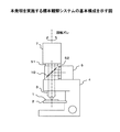
図1は本発明を実施する標本観察システムの基本構成を示している。
図1は、ステージ2と対物レンズ3とを有する顕微鏡装置4に、ポート52を介して画像取得装置6が取り付けられ、更に、ポート51を介してレーザ走査装置7が取り付けられた状態を示しており、ステージ2上には観察対象である標本1が配置されている。
【0022】
画像取得装置6は撮像素子としてCCDが備えられており、標本1の画像を取得する。取得された標本1の画像は同図では図示されていないパーソナルコンピュータ8(以下PC)によって画像情報として取り込まれる。
レーザ走査装置7は標本1に対して刺激を与えるため、あるいは標本1を加工するためにレーザ光を標本1へ照射する。レーザ走査装置7はこのレーザ光を偏向させる手段、本実施形態においては偏向用のミラーを有しており、標本1上の平面において直交しているX方向及びY方向にレーザ光の照射位置を移動させることができ、この照射位置はレーザ走査装置7に接続されるPC8によって制御される。なお、レーザ走査装置7がレーザ光を照射することのできる領域は必ずしも画像取得装置6の画像取得領域と一致していなくともよい。
【0023】
図1に示すように、画像取得装置6及びレーザ走査装置7の光学系は、これらの光軸がポート51及び52を各々通過した後、顕微鏡4内部に設けられているハーフミラー10の作用によって図中の点線で示すように1つの光路に合成され、対物レンズ3を通過して標本1に至るように配置される。
【0024】
これら2つの光学系の間でのずれが生じる要因には、第一に図2に示すような合成されたこれら2つの光軸の位置ずれ(角度を含む)、第二に画像取得装置6及びレーザ走査装置7が取り付けられているポート51及び52での取り付け角度の回転ずれ(光軸の回転ずれ)、第三に両光学系から対物レンズ端までで生じるレンズなどに起因する光学ひずみ、そして第四に画像取得装置6あるいはレーザ走査装置7自身が個々に持つ測定位置のひずみ(リニアリティ)が考えられる。
【0025】
以下、図1に示すシステムの調整の手法について説明する。
まず、調整のための準備として、レーザ光を反射するミラーなどを標本1としてステージ2上に配置する。また画像取得装置6及びレーザ走査装置7は各々標本1の表面でピントが合うように合焦位置の設定がされる。
【0026】
このように両者のピントが合った状態としたときにレーザ走査装置7によってレーザ光をスキャン(走査)させながら画像取得装置6で画像を取得させると、レーザ光の照射されている位置がレーザスポット(点)として表されている画像が取得できる。
【0027】
ここで、画像取得装置6による画像取得の速度とレーザ走査装置7の走査速度との差が十分に大きい場合には、画像取得装置6によって連続して繰り返し取得した画像を重ね合わせることでレーザ照射位置の軌跡が得られる。但し、両者の速度がほぼ同じ場合には、レーザ照射と画像取得との同期がとれないために取得されたレーザの照射位置の間隔が大きく離れてしまい、軌跡の取得がうまくできないことがあるので留意する。
【0028】
また、レーザ走査装置7に音響光学素子などを用いたレーザ光の変調手段がある場合、レーザ光のスキャン中に特定タイミングでレーザ光をON/OFFさせるような変調をレーザ光に与えることによってレーザ光の照射されたタイミングのみのパターンを同様に取得することもできる。
【0029】
このようにして得られた画像からその画像に示されているレーザ光の照射位置を示す画像上の座標(X’,Y’)を測定し、レーザ走査装置7に対して指示したレーザ光の照射位置の指示座標(X,Y)と、この座標(X’,Y’)との差(差異)を各点で算出する。
【0030】
以下、2つの光学系の間でのずれを生じさせる前述した4つの要因のそれぞれについて、その要因に応じたずれの解消の手法について説明する。
まず、前述した第一の原因である、画像取得装置6とレーザ走査装置7との光軸の位置ずれを解消する手法を説明する。
【0031】
図2に示したような画像取得装置6とレーザ走査装置7との光軸のずれによって生じるレーザ光の照射と取得画像との相対的なずれは取得画像の中心位置でのずれとして観測される。つまり、この相対的なずれは、図3に示すように、レーザ走査装置7に対して中心位置への照射を指示したときにレーザ光が実際に照射された照射位置(図3における格子中心)と、そのときに取得された画像の中心位置(図3における画像中心)とのずれを画素数の単位で算出することで知ることができる。
【0032】
レーザ走査装置7の振れ角及び走査領域の範囲は固定されているので、画像表示上で1画素あたりのレーザ光照射の振れ角は、

【0033】
その後、図4に示すように、この振れ角のずれ量θを見込んでレーザ走査装置7の偏向量を予めオフセットさせるように偏向用ミラーによる偏向動作を補正する制御を行えば、結果としてレーザ走査装置7に指示された照射位置の指示座標が座標平面に対して平行に移動されることとなり、画像取得装置6で取得される画像上の位置とレーザ走査装置7によって照射されるレーザ光の照射指示位置とをその画像の中心部において合わせ込むことができる。
【0034】
なお、これらの処理はレーザ走査装置7から発せられるレーザ光の照射位置の制御を行うPC8が所定の制御ソフトウェアを実行することによって実現させることができる。
なお、図4においては、同図における縦方向についてレーザ光照射の振れ角の補正を行うことのみが示されているが、実際には同図における横方向についても同様の補正を行う。
【0035】
次に、2つの光学系の間でのずれを生じさせる前述した第二の要因である、画像取得装置6とレーザ走査装置7との光軸の回転ずれを解消する手法を説明する。
画像取得装置6による画像の取得領域とレーザ走査装置7によるレーザ光の照射領域とが回転するようにずれている状態では、画像取得装置6とレーザ走査装置7との両方もしくは一方の取り付け角度がずれているということがある。このような設置状態において水平方向にレーザ走査装置7を走査して画像取得装置6で画像を取得すると、取得される画像には、図5(a)に示すように、水平ではなく傾きを持ったレーザ光の照射の軌跡が表される。
【0036】
以下、この傾き量を求める。
前述したレーザ光照射の振れ角の補正を行った後に水平方向にレーザ走査装置7を走査して画像取得装置6で画像を取得する。この取得画像からレーザ光の照射位置を示す画像上の座標を2つのポイントにおいて測定し、レーザ走査装置7に対して指示したレーザ光の照射位置の指示座標とをこの2つのポイントで求める。
【0037】
この2つのポイント各々の指示座標とその各々に対応する照射位置の取得画像上の座標とを
【0038】
この角度分の回転ずれを補正するためには、指示座標(x,y)にレーザを照射する場合に、レーザ走査装置7でのレーザ光の偏向量をx方向成分とy方向成分とに分解して−θだけ回転させる座標変換を行えばよい。具体的には、x軸及びy軸の各々について、指示座標(x,y)に対し、
【0039】
なお、これらの処理はレーザ走査装置7から発せられるレーザ光の照射位置の制御を行うPC8が所定の制御ソフトウェアを実行することによって実現させることができる。
次に、2つの光学系の間でのずれを生じさせる前述した第三の要因である、両光学系から対物レンズ端までで生じるレンズなどに起因する光学ひずみを補償する手法を説明する。
【0040】
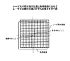
レンズ類などによる光学系のひずみが存在している状態において、その軌跡が等間隔の格子状となるようなレーザ光の照射をレーザ走査装置7に行わせ、その画像を画像取得装置6に取得させる。このようにして取得された画像は、図6(a)に示すように、本来は等間隔であるはずの格子の間隔が変化して表される。
【0041】
この取得画像に表されている格子の升目の位置(画像の中心の升目の交点を原点とする)とその升目の間隔の変化量との関係をプロットしたものが図6(b)のグラフである。このグラフより、照射位置(偏向角度)あたりのひずみ量(ずれ)を関数として表すことができる。
【0042】
ここで、xをレーザ走査装置7に対する照射指示位置(すなわち画像の中心からの距離)、yをレーザ光が実際に照射された照射位置とし、この関数をfとすると、y=f(x)という関係になる。ここで照射される位置yを照射指示位置xとするためには、x=f(x’)となるように入力x’を定める必要がある。
つまり、x’=f−1(x)なる変換をxについて施し、この変換によって得られる値x’をレーザ走査装置7に対する照射指示の値とすればよい。
【0043】
以上のようにすることによって光学系で生じたひずみが補償され、図6(c)に示すように、画像取得装置6で取得される画像にはレーザ光の軌跡が等間隔の格子として表されるようになる。
なお、図6においては、同図における横方向についてレーザ光照射の振れ角の補正を行うことのみが示されているが、実際には同図における縦方向についても同様の補正を行う。
【0044】
また、図6においては軌跡が等間隔の格子状となるようなレーザ光の照射をレーザ走査装置7に行わせているが、所定の照射位置、例えば図6に示す軌跡によって形成されている格子の交点の位置にレーザ光を照射させるようにレーザ走査装置7を制御し、このときの照射指示位置と実際にレーザ光が照射された位置とのずれ量を求め、このずれ量を基にして上述した関数fを更に求め、この関数fの逆関数f−1よりレーザ走査装置7に対する照射指示の値を設定するようにしてもよい。
【0045】
なお、画像取得装置6自身で生じさせているひずみが存在するとしても、このひずみは上述した光学系のひずみの一部として観測されるので、上述した手法で補償を行えば画像取得装置6自身で生じさせているひずみの影響も軽減される。
なお、これらの処理はレーザ走査装置7から発せられるレーザ光の照射位置の制御を行うPC8が所定の制御ソフトウェアを実行することによって実現させることができる。
【0046】
次に、2つの光学系の間でのずれを生じさせる前述した第四の要因である、画像取得装置6あるいはレーザ走査装置7自身が持つ測定位置ひずみを補償する手法を説明する。
いままでに説明した手法を全て行うことにより、レーザ走査装置7によるレーザ光の照射位置が1点に停止している状態の校正は行われる。しかし、レーザ走査装置7によってレーザ光のラスタスキャンを行う場合、常にレーザの位置は移動をしているため、前述の校正を行った項目の他に、レーザ走査装置7自身の応答遅れ(照射位置を移動させるための入力をしてからその指示位置まで照射位置が移動するまでの遅れ時間)や走査位置のひずみ特性(スキャン用の変調信号の変化に対する偏向用ミラーの偏向角度変化の追従性の悪さ)が照射位置のずれに影響を及ぼす。そしてこれらの量は走査速度が速いほど取得画像上での影響が大きくなることが知られている。ここでは、この両者を測定位置ひずみとし、この補償の手法について説明する。
【0047】
まず、レーザ走査装置7においてレーザ光を変調しながら縦方向・横方向にラスタスキャンを行わせ、図7の様な格子状のレーザ光の照射軌跡が標本1に表されるように偏向ミラーの制御を行う。この状態で画像取得を画像取得装置6に行わせると取得画像には格子状の軌跡が示される。
【0048】
いままでに説明した手法を予め全て行っていれば静止状態でのレーザ光の照射位置の校正は既になされている。従って、この取得画像に現れた格子の位置ずれはレーザ走査装置7自身に起因するものである。そこで、この格子の中心位置のずれを前述した画像取得装置6とレーザ走査装置7との光軸の位置ずれを解消する手法と同様に測定する。この中心位置のずれから照射位置のずれが求められる。
【0049】
ラスタスキャンでレーザ光の走査を行う場合、レーザ光の照射位置を変化させるために偏向ミラーに与えられる制御信号とその制御信号に応答して変化する偏向ミラーの向きとは、一般に図8の様な時間関係が認められる。同図においてここで問題としているレーザ走査装置7自身の応答遅れとはこの図におけるt1の部分である。つまり、この制御信号に時間遅れを持たせることなく同期させてレーザ光の照射を行うようにしてしまうと、標本1での照射位置はt1時間前の位置になってしまうということである。
【0050】
この時間遅れはレーザ走査装置7固有の特性のため、この特性をうち消すように制御信号を加工することは難しい。そこで、レーザ光の照射タイミングの制御を行うようにする。具体的には、制御信号からt1時間分遅らせたものからレーザ光の照射タイミングを得るようにしてレーザ光のON/OFF制御を行う。こうすることにより、図8に示すように、所望のレーザ光の照射位置に精度よくレーザを照射することができるようになる。
【0051】
なお、前述した他の手法と同様、この手法でも図7における縦・横の両方向について測定位置ひずみの補償を行うようにする。
なお、これらの処理はレーザ走査装置7から発せられるレーザ光の照射位置の制御を行うPC8が所定の制御ソフトウェアを実行することによって実現させることができる。
【0052】
以下、上述した本発明に係る調整手法の基本原理を用いた具体的な実施例を幾つか説明する。
[実施例1]
図9は実施例1の標本観察システムの構成を示している。
【0053】
同図に示す構成は、CCD撮像装置61を備え、CCD撮像装置61の有するCCD素子によって取得された画像を一旦PC8に取り込んだ後、取得画像をモニ夕9に表示する画像取得装置6と、ミラー11の取り付けられた2つのガルバノメータ12が直交した位置に配置され、レーザ光源13からレーザ導入光路14を経て送られてくるレーザ光をそれそれ標本1の表面において直交するX軸方向及びY軸方向に偏向させることのできるレーザ走査装置7とを組み合わせてなるシステムである。
【0054】
CCD撮像装置61はポート52で顕微鏡4に接続され、対物レンズ3を介して標本1の像を取得する。取得された画像を表現する情報はPC8に取り込まれて処理が施され、標本1の画像としてモニタ9に表示される。またPC8はその取得画像上の特徴点を抽出し、その特徴点の位置を座標として読みとることができる。
【0055】
レーザ走査装置7はPC8によって2つのガルバノメータ12の動作角が制御され、PC8からの指示に応じた角度だけミラー11が移動する。この制御動作が2つのミラー11の各々に対して行われることにより、X軸方向及びY軸方向の各々任意の方向にレーザ光を偏向させることができる。偏向されたレーザ光はレーザ走査装置7との接続部であるポート51を通過し、対物レンズ3を通って標本1に照射される。
【0056】
なお、PC8は、標準的な構成を有するコンピュータ、すなわち、制御プログラムを実行することで各構成要素を制御するCPUと、ROMやRAM及び磁気記憶装置などからなり、CPUに各構成要素を制御させる制御プログラムの記憶やCPUが制御プログラムを実行する際のワークメモリあるいは各種データの記憶領域として使用される記憶部と、ユーザによる操作に対応する各種のデータが取得される入力部と、モニタ9などに各種のデータを提示してユーザに通知する出力部と、ネットワークに接続するためのインタフェース機能を提供するI/F部とを備えるコンピュータである。
【0057】
CCD撮像装置61によって取得される画像上の位置とレーザ走査装置7へのレーザ光照射の指示位置とを整合させる調整を行うとき、まず標本1としてミラーをステージ2上に置く。そして、まずCCD撮像装置61で標本1の表面にピントが合うように顕微鏡4のフォーカスを合わせる。このフォーカス調整を済ませれば、レーザ走査装置7はこの同一の対物レンズ3を介して標本1へレーザ光を照射するため、こちらの光学系におけるフォーカスも標本1の表面に合う。
【0058】
まずレーザ走査装置7の走査領域の中心にレーザ光を照射している状態でCCD撮像装置61によって画像を取得すると、図10に示すように、取得画像の中心付近にレーザスポットが表示される。このスポットの座標と取得画像の中心の座標との差がCCD撮像装置61とレーザ走査装置7との光軸のずれになる。
【0059】
このずれ量を前記の換算式(1)を利用してレーザ走査装置7のミラー11の振れ角へと変換する。そして、図4に示したように、この振れ角に当たる量だけレーザ走査装置7のミラー11の振れ角をオフセットさせて駆動させるようにする。この結果レーザ光の走査領域の中心と取得画像の中心は一致し、CCD撮像装置61とレーザ走査装置7との光軸の位置ずれが補正される。
【0060】
次に、これらの中心の補正を行った後に、画像取得範囲における例えば中心から水平あるいは垂直の位置に存在するいずれかの端の一点にレーザ光を照射し、これらの照射点の画像上のずれ量を画素数の単位で測定する。このずれ量を式(3)に当てはめるのだが、先に行った補正によって取得画像の中心は既に一致させているので、CCD撮像装置64を基準としたレーザ走査装置7のポート51への取り付け向きの回転ずれθは
【0061】
以降、レーザ走査装置7で指示座標(x,y)の位置にレーザ光の照射を行うときには、この(x,y)の値と上式によって求めたθとを式(4)に代入して得られる値で2つのガルバノメータ12を駆動する。こうすることで、前記の取り付けの回転ずれが補正され、図6に示したように、レーザ光を精度よく走査することができる。
【0062】
次に、PC8で行わせている処理を変更し、CCD撮像装置61で取得された画像を重ね合わせてモニタ9に表示させるようにする。この処理によりレーザ光を標本1上で走査させるとレーザ光の照射箇所は光量が上がるため、レーザ光の照射された点が軌跡となって表示される。
【0063】
ここで、レーザ走査装置7を制御して一定間隔の直線あるいは格子が軌跡として得られるようにレーザ光を走査させるようにする。このとき光学系などのひずみが存在する場合、CCD撮像装置61で取得された画像に現れる直線の間隔が一定ではなくなる。このとき、この変化した間隔を測定し、xをレーザ走査装置7に対する照射指示位置、そしてyをレーザ光が実際に照射された照射位置と照射指示位置とのずれとし、xとyとの関係を示す関数y=f(x)を求める。この関数は、例えば予め関数の次数を定めておき、各係数を最小二乗法等の使用によって推定することで獲得することができる。
【0064】
その後、このようにして得られた関数の逆関数f−1(x)を導き、以降、レーザ走査装置7で指示座標の位置にレーザ光の照射を行うときには、この指示座標の値をこの逆関数に入力して変換し、この変換によって得られた値でガルバノメータ12を駆動する。こうすることで、画像取得装置6とレーザ走査装置7との両光学系で生じるレンズなどに起因する光学ひずみが補償される。
【0065】
なお、上述した各処理はCCD撮像装置6及びレーザ走査装置7の制御を行うPC8が予め用意されている制御プログラムを実行することによって実現される。
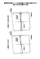
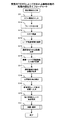
ここで図11について説明する。同図はこの実施例1においてPC8によって行われる制御処理の処理内容を示すフローチャートである。同図に示す処理は上述した制御プログラムをPC8で実行させることによって行われる。
【0066】
図11(a)は、CCD撮像装置61とレーザ走査装置7との光軸の位置ずれの補正処理の処理内容を示している。
まず、S111において、まずミラーを標本1としてステージ2上にセットすることをこのシステムの使用者に促す表示をモニタ9に表示させる。
【0067】
ミラーのセットが確認されたら処理はS112に進み、CCD撮像装置61での取得画像のピントが合うように顕微鏡4のフォーカスを合わせる操作をこのシステムの使用者に促す表示をモニタ9に表示させる。なお、この処理として、PC8がCCD撮像装置61での取得画像に基づいて顕微鏡4のフォーカスを自動的に制御するいわゆるオートフォーカス制御処理を行うようにしてもよい。
【0068】
フォーカス調整の完了が確認されたら処理はS113に進み、レーザ走査装置7を制御し、その走査領域の中心の座標を指定してレーザ光を照射させる。そして続くS114においてCCD撮像装置61にこの画像を取得させ、PC8にこの画像を表している情報を取り込む。
【0069】
S115では取得された画像からレーザスポットを見つけ出し、このレーザスポットの画像上における座標を取得する。
S116では、S113の処理においてレーザ走査装置7に対して指定したその走査領域の中心の座標と、S115の処理によって取得されたレーザスポットの画像上における座標との差を求めてCCD撮像装置61とレーザ走査装置7との光軸のずれ量を算出し、前記の換算式(1)を利用してこのずれ量をレーザ走査装置7のミラー11の振れ角へと変換する。
【0070】
S117ではレーザ走査装置7を制御し、S116の処理によって得られた振れ角だけミラー11の振れ角をオフセットさせる。
以上までの処理がCCD撮像装置61とレーザ走査装置7との光軸の位置ずれの補正処理である。
【0071】
次に図11(b)の処理を説明する。この処理はCCD撮像装置61とレーザ走査装置7との光軸の回転ずれの補正処理の処理内容を示している。
なお、この処理は前述したCCD撮像装置61とレーザ走査装置7との光軸の位置ずれの補正処理を完了してから行うようにする。
【0072】
同図におけるS121及びS122の処理はそれぞれ前述した図11(a)のS111及びS112の処理と同様である。
S122の処理の後、フォーカス調整の完了が確認されたら処理はS123に進み、レーザ走査装置7を制御し、その走査領域の中心から水平あるいは垂直の位置に存在するいずれかの端の一点にレーザ光を照射させる。そして続くS124においてCCD撮像装置61にこの画像を取得させ、PC8にこの画像を表している情報を取り込む。
【0073】
S125では取得された画像からレーザスポットを見つけ出し、このレーザスポットの画像上における座標を取得する。
S126では、S123の処理においてレーザ走査装置7に対して指定したその照射位置の座標と、S125の処理によって取得されたレーザスポットの画像上における座標とを前記の換算式(5)に代入し、CCD撮像装置61とレーザ走査装置7との光軸の回転ずれの角度を算出する。
【0074】
S127では、S126の処理によって得られた角度を前記の(4)式に代入し、ガルバノメータ12の駆動指示をこの(4)式によって算出される値に基づいて行うようにレーザ走査装置7の制御処理の設定を行う。
以上までの処理がCCD撮像装置61とレーザ走査装置7との光軸の回転ずれの補正処理である。
【0075】
次に図11(c)の処理を説明する。この処理は画像取得装置6とレーザ走査装置7との両光学系で生じる光学ひずみの補償処理の処理内容を示している。
なお、この処理は前述したCCD撮像装置61とレーザ走査装置7との光軸の位置ずれ及び回転ずれの両補正処理を完了してから行うようにする。
【0076】
同図におけるS131及びS132の処理はそれぞれ前述した図11(a)のS111及びS112の処理と同様である。
S132の処理の後、フォーカス調整の完了が確認されたら処理はS133に進み、レーザ走査装置7を制御し、その走査領域の四隅を含む領域内の複数の位置のいずれかにレーザ光を照射させる。そして続くS133においてCCD撮像装置61にこの画像を取得させ、PC8にこの画像を表している情報を取り込み、既に得られている画像と重ね合わせる。そして、S135においてこのS133及びS134の処理を所定数回繰り返し、レーザ光の照射位置の軌跡が表されている画像を作成する。
【0077】
なお、S133において、走査領域の四隅をレーザ照射の位置として特掲しているのは、この位置が最も大きな光学ひずみを受けていると考えられるからである。
S135の判定処理の結果がYesとなり、S133及びS134の処理の所定回数の繰り返しが完了したときにはS136へと処理が進み、レーザ光の照射位置の軌跡が表されている画像から、その軌跡を構成している全てのレーザスポットの画像上における座標を取得する。
【0078】
続くS137において、S133の処理においてレーザ走査装置7に対して指定したレーザ光の照射位置の座標と、S136の処理によって取得されたレーザスポットの画像上における座標との差を算出する。
S138では、S137の算出結果から、S133の処理においてレーザ走査装置7に対して指定したレーザ光の照射位置の座標と、その指定座標でのレーザ光の照射位置のずれとの関係を示す関数を求める。
【0079】
S139では、S138の処理によって得られた関数の逆関数を算出し、ガルバノメータ12の駆動指示をこの逆関数による変換によって得られる値に基づいて行うようにレーザ走査装置7の制御処理の設定を行う。
以上までの処理が画像取得装置6とレーザ走査装置7との両光学系で生じる光学ひずみの補償処理である。
【0080】
なお、以上までに説明した各処理によって一旦得られた調整のための各値をPC8の有する記憶装置に格納しておくようにすれば、このシステムの使用開始時にこれらの調整処理を毎度行うような手間を省くことができる。
また、実施例1においてはレーザ光の照射位置をCCD撮像装置61による取得画像に表すために標本1としてミラーを用いたが、その代わりに一様に染色され、レーザ光によって励起される蛍光標本を用いるようにしてもよい。また、CCD撮像装置61の画像取得感度が十分に高いのであればガラス表面の反射を取得するようにしてもよい。また、実施例1では画像取得装置6としてCCD撮像装置61を用いたが、TVカメラ等の撮像装置であってもよい。
【0081】
また、実施例1のシステムは画像取得装置6とレーザ走査装置7とを1つずつ備えた構成としていたが、複数の画像取得装置6を設け、個別にレーザ走査装置7との間のずれを補償する調整値を求めるようにしてもよい。
[実施例2]
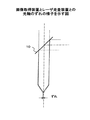
図12は実施例2の標本観察システムの構成を示している。同図に示す構成と図9に示した実施例1の構成との違いは、顕微鏡4の透過像位置にCCD撮像装置61を配置し、落射側にレーザ走査装置7を配置した点にある。この実施例2のような構成は、CCD撮像装置61が標本1の微分干渉像などの透過像を取得するために好適なものである。
【0082】
この実施例2に示す構成では、レーザ走査装置7から照射されたレーザ光は対物レンズ3を通過し標本面と反対側のCCD撮像素子61に直接照射される。このため実施例1のように両者の照射位置を調整する場合、実施例1では撮像素子にレーザ光を送るため標本1としてミラーを配置したが、実施例2ではこのような調整用の標本1は不要である。
【0083】
なお、この実施例2において、CCD撮像装置61によって取得される画像上の位置とレーザ走査装置7へのレーザ光照射の指示位置とを整合させる調整の手順は実施例1と全く同じである。
また、この実施例2においてPC8によって行われる制御処理の処理内容を示すフローチャートを図13に示す。同図を図11に示したフローチャートと比較すると分かるように、図11におけるS111、S121、S131の処理、すなわちミラーを標本1としてステージ2上にセットすることを使用者に促す処理が図13に示されている処理では行われないことを除けば、この両処理は同様の処理である。
【0084】
なお、この図12に示した実施例2のシステムではステージ2の真下にCCD撮像装置61を配置したが、この位置は標本1の透過画像が結像する位置であればステージ2の真下に限定されるものではない。また、実施例2では画像取得装置6としてCCD撮像装置61を用いたが、TVカメラ等の撮像装置であってもよい。
[実施例3]
実施例3は、実施例1におけるレーザ走査装置7若しくはレーザ光源13がレーザ光の変調を行う変調部を備えているというシステムである。音響光学素子を用いたAOM(Acoustic Optical Modulator)やAOTF(Acoustic Optical Tunable Filter )を備えたレーザ光の変調部を有していれば、スキャニング中に高速でレーザ光のON/OFF制御を行うことで容易に特定領域の範囲だけにレーザ光の照射を行うことができる。なお、このシステムではレーザ走査装置7若しくはレーザ光源13に備えられている変調部をPC8によって制御可能なように構成する。
【0085】
このシステムでは、まずレーザ光が常に照射される状態にレーザ走査装置7を設定した上で、前述した実施例1におけるものと同様の調整を行い、CCD撮像装置61とレーザ走査装置7との光軸の位置ずれ及び回転ずれの補正、並びに両光学系で生じる光学ひずみの補償を行う。
【0086】
次に、画像取得装置6あるいはレーザ走査装置7自身が持つ測定位置ひずみを補償するための調整を行う。
具体的には、レーザ走査装置7を制御してラスタスキャンを行なわせながら照射中のレーザ光を変調し、図10に示したような格子模様にレーザ光が走査されるようにする。この状態でCCD撮像装置61に画像の取得を行わせるとその画像に格子状の軌跡が表れる。先に、静止状態(スキャンを行わない状態)での調整は終えているのでここで表示された格子の位置ずれはすべてレーザ走査装置7自身に起因している。そこで、この格子の中心位置のずれを前述した画像取得装置6とレーザ走査装置7との光軸の位置ずれを解消する手法と同様に測定する。
そして、この中心位置のずれから応答遅れ(レーザ光照射のタイミングずれ)を算出する。
【0087】
ここで算出タイミングのずれ量であるt1時間分だけ、レーザ光の照射タイミングを遅らせるようにレーザ走査装置7を制御する。すなわち、図8に示したように、照射指示の入力に対してt1時間分遅らせてレーザのON/OFF制御を行う。こうすることによりレーザ光の照射を所望の位置に行えるようになる。
【0088】
なお、上述した各処理はCCD撮像装置6及びレーザ走査装置7の制御を行うPC8が予め用意されている制御プログラムを実行することによって実現される。
ここで図14について説明する。同図はこの実施例3においてPC8によって行われる制御処理のうち、画像取得装置6あるいはレーザ走査装置7自身が持つ測定位置ひずみの補償処理の処理内容を示している。
【0089】
なお、この処理は前述したCCD撮像装置61とレーザ走査装置7との光軸の位置ずれ及び回転ずれの両補正処理、並びに両光学系で生じる光学ひずみの補償処理を完了してから行うようにする。
同図におけるS311及びS312の処理はそれぞれ前述した図11(a)のS111及びS112の処理と同様である。
【0090】
フォーカス調整の完了が確認されたら処理はS313に進み、レーザ走査装置7を制御してレーザ光を照射させ、その走査領域を走査させる。ここで続くS314においてレーザ走査装置7に指示を与えてレーザ光を変調し、図10に示したような格子模様にレーザ光が走査されるようにする。そして続くS315においてCCD撮像装置61にこの画像を取得させ、PC8にこの画像を表している情報を取り込む。
【0091】
S316では、S315の処理によって取得された画像に表されているレーザ光の軌跡における格子の中心の交点の画像上における座標を取得する。
S317では、S315の処理によって取得された画像の中心の座標とS316の処理によって取得された格子の中心の交点の座標との差を求め、この差を時間の単位に変換する。この変換は、両座標の距離をレーザ光の走査速度で除算することによって行われる。この変換によって、格子の中心の交点の座標の照射指示がされた時刻と、格子の中心の交点の座標が照射された時刻との時間差が得られる。
【0092】
S318では、レーザ光走査装置7内においてレーザ光の照射のタイミングの制御信号をS317の処理によって得られた時間だけ遅らせる設定を行う。
以上までの処理が画像取得装置6あるいはレーザ走査装置7自身が持つ測定位置ひずみの補償処理である。
【0093】
なお、以上までに説明した処理によって一旦得られた調整のための各値をPC8の有する記憶装置に格納しておくようにすれば、このシステムの使用開始時にこれらの調整処理を毎度行うような手間を省くことができる。
また、レーザの変調を行う手段として本実施例では音響光学素子を用いたが、レーザ自身で変調を与えることのできる半導体レーザを用いるようにしてもよい。
【0094】
また、調整時にレーザ光を照射させて生成する軌跡のパターンは、図10に示したような升目の格子パターンでなくとも、中心位置と等間隔に並んだ何カ所かの照射位置とが読みとれるようなパターンであればどのようなでもよい。
なお、前述した画像取得装置6あるいはレーザ走査装置7自身が持つ測定位置ひずみのうち、走査位置のひずみ特性に関しては、走査範囲の両端付近を除く範囲においてひずみ無くほぼ一定の速度で走査をさせるように駆動させる技術はすでに数多く存在するので、この周知の技術を採用することで走査ひずみの補償をおこなうようにしてもよい。
【0095】
なお、実施例3は、実施例1におけるレーザ走査装置7がレーザ光の変調を行う変調部を備えているというシステムとしたが、実施例2におけるレーザ走査装置7がレーザ光の変調を行う変調部を備えているというシステムであっても実施例3において行ったものと同様の調整手法を採用することができる。
[実施例4]
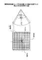
図15は実施例4の標本観察システムの構成を示している。同図に示す構成と図9に示した実施例1の構成との大きな違いは、画像取得装置6としてCCD撮像装置61の代わりにレーザ走査型顕微鏡62が装備されている点にある。
【0096】
レーザ走査型顕微鏡装置62(以下、「LSM」と称することとする)は、レーザ走査装置7と同様に、ミラー110の取り付けられた2つのガルバノメータ120でレーザ光源130から発せられたレーザ光を偏向させ、標本1面にレーザを照射する。標本面に当てられたレーザ光の反射光あるいは蛍光は対物レンズ3を通過してダイクロイックミラー140で反射され、光電子増倍管やフォトダイオードなどを有して構成される検出装置150に送られ、光の強度の変化として記録される。この光強度の変化情報が画像情報としてPC8に送られ、PC8において画像として構成される。またPC8はその取得画像上の特徴点を抽出し、その特徴点の位置を座標として読みとることができる。
【0097】
レーザ走査装置7はPC8によって2つのガルバノメータ12の動作角が制御され、PC8からの指示に応じた角度だけミラー11が移動する。この制御動作が2つのミラー11の各々に対して行われることにより、X軸方向及びY軸方向の各々任意の方向にレーザ光を偏向させることができる。偏向されたレーザ光はレーザ走査装置7との接続部であるポート51を通過し、対物レンズ3を通って標本1に照射される。
【0098】
LSM62によって取得される画像上の位置とレーザ走査装置7へのレーザ光照射の指示位置とを整合させる調整を行うとき、まず標本1としてミラーをステージ2上に置く。そして、まずCCD撮像装置61で標本1の表面にピントが合うように顕微鏡4のフォーカスを合わせる。このフォーカス調整を済ませれば、レーザ走査装置7はこの同一の対物レンズ3を介して標本1へレーザ光を照射するため、こちらの光学系におけるフォーカスも標本1の表面に合う。
【0099】
この実施例4のシステムに対して行う調整手法は、実施例1と全く同じ手順で行うことができるので説明は省略する。
なお、レーザ走査装置7から照射されたレーザ光の照射位置が表されている画像をLSM62で取得できるようにするためにへ映し出すために標本1としてミラーを用いたが、その代わりに一様に染色され、レーザ光によって励起される蛍光標本を用いるようにしてもよい。また、LSM62の画像取得感度が十分に高いのであればガラス表面の反射を取得するようにしてもよい。
【0100】
更に、一様な蛍光標本の各点に高エネルギーのレーザ光を照射することで、部分的に蛍光退色をおこさせ、LSM62でその退色痕を観察測定するようにして調整を行うこともできる。こうすることにより、レーザ光の照射位置の軌跡を得るためにPC8で画像を累積合成する処理が不要となる。
【0101】
また、実施例4ではレーザ走査装置7が専らレーザ光を照射するための装置としていたが、レーザ走査装置7へ戻ってくるレーザ光の強度を測定する検出装置を備えているもの、例えば、レーザ走査装置7としてもLSMを用いて2つのLSMを組み合わせたシステムを構成し、その一方をレーザ走査装置7として機能させ、他方を画像取得装置6として機能させるようにしてもよい。
[実施例5]
実施例5は、実施例4におけるレーザ走査装置7若しくはレーザ光源13がレーザ光の変調を行う変調部を備えているというシステムである。この実施例5のシステムに対して行う調整手法は、実施例3と全く同じ手順で行うことができるので説明は省略する。
[実施例6]
実施例6は、実施例1、3、4、または5のシステムであるレーザ走査装置7若しくはレーザ光源13がレーザ光の変調を行う変調部を備えているシステムであり、これらのシステムで、取得画像中におけるレーザ光を照射する位置・範囲が予め特定されている場合の調整の手法である。
【0102】
まず、実施例1または実施例4のシステムでの調整の手法を説明する。
前述した実施例1または実施例4では、画像取得装置6で取得される画像の中心付近に表れるレーザスポットの位置に基づいて光軸の位置ずれの補正を行い、またその光軸の位置ずれの補正結果に基づいて、光軸の回転ずれ及び光学系のひずみの補償を行うようにしていた。これに対し、これに対し、実施例6では、レーザ光の照射位置が実験前に予め特定されているような場合に、この照射位置に基づいて光軸の位置ずれの補正を行い、またその光軸の位置ずれの補正結果に基づいて、光軸の回転ずれ及び光学系のひずみの補償を行うようにする。こうすることにより、その指定領域内においては、実施例1または実施例4による調整のみによるものよりも更に精度の良い光学ひずみの補償が可能となる。
【0103】
次に、実施例3または実施例5のシステムでの調整の手法を説明する。
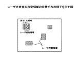
前述した実施例3または実施例5では、画像取得装置6で取得される画像の中心部で観測されるレーザ光照射のタイミングずれに基づいてレーザ光の走査範囲の全域に渡る光学ひずみの補償を行っていた。これに対し、実施例6では、例えば蛍光を発する標本1に部分的に蛍光退色を起こさせる等の目的で、図16に示すように、標本1における特定の領域のみを走査するようにその変調部を制御してレーザ光を照射させるときにおける、領域の指定範囲と実際にレーザ光が照射される領域との位置ずれを補正する手法を説明する。
【0104】
まず、前述した光軸、回転、光学ひずみの調整を、指定領域の中心(微小領域走査の中心)の位置に基づいて全て行う。これにより、指定領域の中心(微小領域走査の中心)付近に対してレーザ光を照射させることが可能となる。
ここで、指定領域分のみにレーザ光を照射するために、指定領域の範囲にレーザ光が照射される角度にミラー11の角度が達したときにレーザ光を照射する必要がある。
【0105】
このような照射を可能とするためには、前述した実施例3の調整手法を適用してレーザ光照射のタイミングずれを算出し、レーザ走査装置7に対して指定領域の開始位置に照射させるためのタイミングから時間t1だけ遅らせてレーザを照射し、同様に指定領域の終止位置に照射させるためのタイミングから時間t1だけ遅らせてレーザ光の照射を中断する。これを繰り返すことで指定の領域に正しくレーザ照射を行うことが可能となる。また、このように指定の領域内で観測されるレーザ光照射のタイミングずれに基づいてレーザ光の走査範囲である指定領域内における光学ひずみの補償を行うことにより、その指定領域内においては、実施例3または実施例5による調整のみによるものよりも更に精度の良い光学ひずみの補償が可能となる。
【0106】
なお、上述した各処理はCCD撮像装置6及びレーザ走査装置7の制御を行うPC8が予め用意されている制御プログラムを実行することによって実現される。
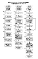
ここで図17について説明する。同図はこの実施例6においてPC8によって行われる制御処理の処理内容を示すフローチャートである。同図に示す処理は上述した制御プログラムをPC8で実行させることによって行われる。
【0107】
図17(a)は、実施例1または実施例4のシステムにおいて予め特定されている指定位置へのレーザ光の照射を行うときの制御処理の処理内容を示している。
まず、S611において、観察・実験対象である蛍光を発する標本1をステージ2上にセットすることをこのシステムの使用者に促す表示をモニタ9に表示させる。
【0108】
標本1のセットが確認されたら処理はS612に進み、CCD撮像装置61での取得画像のピントが合うように顕微鏡4のフォーカスを合わせる操作をこのシステムの使用者に促す表示をモニタ9に表示させる。なお、この処理として、PC8がCCD撮像装置61での取得画像に基づいて顕微鏡4のフォーカスを自動的に制御するいわゆるオートフォーカス制御処理を行うようにしてもよい。
【0109】
S612の処理の後、フォーカス調整の完了が確認されたら処理はS613に進み、CCD撮像装置61(あるいはLSM62)にこの画像を取得させ、PC8にこの画像を表している情報を取り込む。
S614では、S613の処理によって取り込まれた画像をモニタ9に表示させ、レーザ光を照射する指示位置をこの表示画像上から選択することをこのシステムの使用者に促す表示をモニタ9に表示させる。
【0110】
使用者による指示位置の選択が確認されたら処理はS615に進み、この指示位置の座標を取得する。
S616では照射指示位置の座標からレーザ走査装置7への入力値への変換処理が行われる。この処理は、具体的には、図11(a)のS113からS117にかけての処理、図11(b)のS123からS127にかけての処理、および図11(c)のS131からS138にかけての処理を順に行って、S615の処理によって取得された指示位置の座標に基づいた光軸の位置ずれ及び回転ずれの補正処理並びに光学ひずみの補償処理を行う。そして、これらの処理によって算出された各設定値を用いてS615の処理によって取得された指示位置の座標の変換を行う。
【0111】
S617では、S616の処理における変換によって得られた座標をレーザ走査装置7へ送付し、続くS618において、その送付された座標を照射指示座標としたレーザ光の照射の設定をレーザ走査装置7に行う。
S619では、S618の処理によってなされたレーザ光の一点照射の設定の下で所定の実験・観察がこのシステムの使用者によって行われる。
【0112】
以上までの処理が実施例1または実施例4のシステムにおいて予め特定されている指定位置へのレーザ光の照射を行うときの制御処理である。
次に図17(b)の処理を説明する。この処理は実施例3または実施例5のシステムにおいて予め特定されている指定領域へのレーザ光の走査を行うときの制御処理の処理内容を示している。
【0113】
同図におけるS621及びS622の処理はそれぞれ前述した図17(a)のS611及びS612の処理と同様である。
S622の処理の後、フォーカス調整の完了が確認されたら処理はS623に進み、CCD撮像装置61(あるいはLSM62)にこの画像を取得させ、PC8にこの画像を表している情報を取り込む。
【0114】
S624では、S623の処理によって取り込まれた画像をモニタ9に表示させ、レーザ光を照射する指示領域をこの表示画像上から選択することをこのシステムの使用者に促す表示をモニタ9に表示させる。
使用者による指示領域の選択が確認されたら処理はS625に進み、この指示領域を特定するための座標、例えば指示領域を囲む矩形の各頂点の座標と、この指示領域を代表する位置の座標、例えば指示領域の中心の座標とを取得する。
【0115】
S626では照射指示領域の座標からレーザ走査装置7への入力値への変換処理が行われる。この処理は、具体的には、図11(a)のS113からS117にかけての処理、図11(b)のS123からS127にかけての処理、および図11(c)のS131からS138にかけての処理を順に行って、S625の処理によって取得された指示領域を代表する位置の座標に基づいた光軸の位置ずれ及び回転ずれの補正処理並びに光学ひずみの補償処理を行う。そして、これらの処理によって算出された各設定値を用いてS625の処理によって取得された指示領域を特定するための座標の変換を行う。
【0116】
S627では、S626の処理における変換によって得られた各座標をレーザ走査装置7へ送付する。
S628では、照射指示領域の座標からレーザ光の変調信号に与える遅延時間への変換処理が行われる。この処理は、図14のS316からS318にかけての処理を行ってS625の処理によって取得された指示領域を代表する位置の座標に基づいた測定位置ひずみの補償処理を行う。
【0117】
S629では、S628の処理における変換によって得られた遅延時間だけ送られた変調信号をレーザ光の変調部へ送付する。
S630では、S627の処理によって送付された各座標で特定される領域を照射指示領域としたレーザ光の走査の設定をレーザ走査装置7に行う。
【0118】
S631では、S630までの処理によってなされたレーザ光の走査の設定の下で所定の実験・観察がこのシステムの使用者によって行われる。
以上までの処理が実施例3または実施例5のシステムにおいて予め特定されている指定領域へのレーザ光の走査を行うときの制御処理である。
[実施例7]
実施例7は、実施例3または5のシステムに対して実施例6のようにして行われた指定領域の走査における領域の指定範囲と実際にレーザ光が照射される領域とのずれの補正を、レーザ光の変調部を有しない実施例1、2、または4のシステムにおいて行うものである。
【0119】
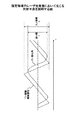
実施例1、2、及び4のシステムはいずれもレーザ光の変調部を有していないため、前述したような指定領域の走査を行うためにレーザ光をON/OFFすることができない。このため、照射領域はレーザの振れ角、すなわちミラー11の振れ角そのものとなる。ところが、図18に示すように、ミラー11を駆動するための制御信号とミラー11の実際の振れ角との間には応答遅れがあるため一致しない。そのため、所望の領域にレーザ光を照射しようとしても、その所望の領域よりも狭い範囲にしかレーザ光を照射することができないことがある。しかも、この照射不良の範囲は、ミラー11を高速に動作させようとしてミラー11の駆動制御信号の周波数を高めればそれだけ拡大してしまう。
【0120】
この照射不良の範囲を減少させるため、前述した実施例1、2、4の各々の調整手法を予め行っておき、その後に特定の領域走査を行ったときの実際の照射範囲をレーザ光の照射位置の軌跡として測定し記録しておく。そして、ミラー11の駆動制御信号に対して振れ角が不足する分だけ、その駆動制御信号の振幅を増加させてミラー11の振れ角をそれだけ大きくする。
【0121】
このときの駆動制御信号の振幅の増加比率は以下のようにして求める。
図18において、レーザ光の走査を行わせるためにミラー11へ制御信号を与えてレーザを走査させたときのミラー11の動きは図中の波形のようになり、標本1上での振れ幅はbになる。このbの幅を画像取得装置6で測定することにより、その制御信号によって指示を行っているレーザ光の振れ幅aとの比率b/aを求めることができる。この比率は、指示を行っているレーザ光走査の範囲と実際に走査された範囲との差異を示すものである。
【0122】
ここで、この比率b/aだけミラー11の振れ角を拡大させる。こうすることで、レーザ光の走査範囲が拡大され、標本1上で必要な振れ幅を確保できるようになる。
なお、この比率は駆動制御信号波形の形状によって異なるのでレーザ光の走査に使う波形毎にその比率を求めておく必要がある。
【0123】
なお、上述した各処理はCCD撮像装置6及びレーザ走査装置7の制御を行うPC8が予め用意されている制御プログラムを実行することによって実現される。
ここで図19について説明する。同図はこの実施例7においてPC8によって行われる制御処理であって、レーザ光の変調部を有していない実施例1、2、及び4のシステムにおいて予め特定されている指定領域へのレーザ光の走査を行うための処理の処理内容を示すフローチャートである。同図に示す処理は上述した制御プログラムをPC8で実行させることによって行われる。
【0124】
同図におけるS711及びS712の処理はそれぞれ前述した図11(a)のS111及びS112の処理と同様である。
S712の処理の後、フォーカス調整の完了が確認されたら処理はS713に進み、CCD撮像装置61(あるいはLSM62)にこの画像を取得させ、PC8にこの画像を表している情報を取り込む。
【0125】
S714では、S713の処理によって取り込まれた画像をモニタ9に表示させ、レーザ光を照射する指示領域をこの表示画像上から選択することをこのシステムの使用者に促す表示をモニタ9に表示させる。
使用者による指示領域の選択が確認されたら処理はS715に進み、この指示領域を代表する位置の座標、ここでは指示領域の中心の座標を取得する。
【0126】
S716では照射指示領域の座標からレーザ走査装置7への入力値への変換処理が行われる。この処理は、具体的には、図11(a)のS113からS117にかけての処理、図11(b)のS123からS127にかけての処理、および図11(c)のS131からS138にかけての処理を順に行って、S715の処理によって取得された指示領域の中心の位置の座標に基づいた光軸の位置ずれ及び回転ずれの補正処理並びに光学ひずみの補償処理を行う。
【0127】
S717では、S714の処理によって確認された指示領域についてS716の処理による変換を施してレーザ光の走査を行ったときの走査範囲の四隅の座標を取得する。
S718では、S717の処理によって取得された座標から、ミラー11への制御信号によって走査させようとしているレーザ光の振れ幅aに対する標本1上で本来走査させようとしているレーザ光の走査幅bを求めて比率b/aの計算を行う。
【0128】
S719では、標本1がミラーから観察対象のものへと取り替えられ、S718の処理によって算出された比率だけミラー11の振れ角を拡大させる設定をレーザ走査装置7に対して行う。
S720では、S714の処理によって確認された指示領域についてS716の処理による変換を施した後の位置を中心としてレーザ光を走査する設定をレーザ走査装置7に行う。
【0129】
S721では、標本1がミラーから観察対象のものへと取り替えられ、S720までの処理によってなされたレーザ光の走査の設定の下で所定の実験・観察がこのシステムの使用者によって行われる。
以上までの処理がレーザ光の変調部を有していない実施例1、2、及び4のシステムにおいて予め特定されている指定領域へのレーザ光の走査を行うための処理である。このようにして調整を行うことにより、レーザ光の変調部を有していないシステムであっても、指定の領域をレーザ光で精度よく照射することができるようになる。
【0130】
なお、以上までに説明した処理によって一旦得られた調整のための値をPC8の有する記憶装置に格納しておくようにすれば、このシステムの使用開始時にこれらの調整処理を毎度行うような手間を省くことができる。
【0131】
【発明の効果】
以上詳細に説明したように、本発明は、標本の像が表されている画像を取得する画像取得部を有する画像取得装置と、該標本にレーザ光を照射するレーザ光照射部を有するレーザ光走査装置とを備えている標本観察システムにおいて、レーザ光照射部によって照射されたレーザ光の照射位置を画像取得部で取得された画像から測定し、この測定により得られた照射位置とレーザ光照射部に対して指示されたレーザ光照射の照射指示位置との差異を示す情報に基づいて、レーザ光照射部の照射位置を校正するようにする。
【0132】
こうすることにより、レーザ光の照射位置を測定するための専用の測定手段や特別の工具を用いることなくレーザ光の照射位置の調整をおこなうことができるようなるという効果を奏する。
【図面の簡単な説明】
【図1】本発明を実施する標本観察システムの基本構成を示す図である。
【図2】画像取得装置とレーザ走査装置との光軸のずれを示す図である。
【図3】レーザ光の照射指示位置と取得画像におけるレーザ光の照射位置とのずれの様子を示す図である。
【図4】画像取得装置とレーザ走査装置との光軸の位置ずれの補正の方法を説明する図である。
【図5】画像取得装置とレーザ走査装置との光軸の回転ずれ補正の手法を説明する図である。
【図6】レンズ等で生じる光学ひずみの補償の手法を説明する図である。
【図7】格子状のレーザ光の照射軌跡を示す図である。
【図8】偏向ミラーの制御信号と変更ミラーの位置変化との時間関係を示す図である。
【図9】実施例1の標本観察システムの構成を示す図である。
【図10】レーザスポットが表されている取得画像の例を示す図である。
【図11】実施例1のPCによって行われる制御処理の処理内容を示すフローチャートである。
【図12】実施例2の標本観察システムの構成を示す図である。
【図13】実施例2のPCによって行われる制御処理の処理内容を示すフローチャートである。
【図14】測定位置ひずみの補償処理の処理内容を示すフローチャートである。
【図15】実施例4の標本観察システムの構成を示す図である。
【図16】レーザ光走査の指定領域の位置ずれの様子を示す図である。
【図17】実施例6のPCによって行われる制御処理の処理内容を示すフローチャートである。
【図18】指定領域のレーザ光走査において生じる照射不良を説明する図である。
【図19】実施例7のPCによって行われる制御処理の処理内容を示すフローチャートである。
【符号の説明】
1 標本
2 ステージ
3 対物レンズ
4 顕微鏡装置
51、52 ポート
6 画像取得装置
61 CCD撮像装置
62 レーザ走査型顕微鏡装置
7 レーザ走査装置
8 PC
9 モニタ
10 ハーフミラー
11、110 ミラー
12、120 ガルバノメータ
13、130 レーザ光源
14 レーザ導入光路
140 ダイクロイックミラー
150 検出装置[0001]
TECHNICAL FIELD OF THE INVENTION
The present invention relates to a technique used in an image acquisition device that acquires an image in which an image of a specimen is represented, and in particular, a position on an image of an image acquired by the image acquisition device, and a laser beam applied to the specimen. The present invention relates to a technique for reducing a deviation from an irradiation position.
[0002]
[Prior art]
Conventionally, a deviation between a position of an image obtained by an image obtaining apparatus that obtains an image representing an image of a specimen on an image and an irradiation position of laser light in a laser scanning apparatus that irradiates the specimen with laser light. As a technique for reducing the deviation, a method of absorbing the deviation of the optical axis only by the assembling accuracy of the two devices, a method disclosed in
[0003]
In addition, as a technique of superimposing separate images representing the same specimen acquired by a plurality of image acquisition apparatuses, the image itself is processed after acquiring the image, as in the technique disclosed in
[0004]
[Patent Document 1]
JP-A-11-242164
[Patent Document 2]
JP-A-11-231223
[0005]
[Problems to be solved by the invention]
In the prior art described above, since the adjustment of the optical system is only performed independently by the image acquisition device alone or the laser scanning device alone, the deviation of the optical axis between the two depends on the assembly accuracy, It was virtually uncontrolled.
[0006]
Therefore, when a plurality of different images are obtained by combining a plurality of image obtaining apparatuses, an image processing means for performing a process of superimposing the obtained images of the same specimen is required. However, such image processing requires a huge amount of processing, and a large processing load is required to perform the overlay processing in real time.
[0007]
Further, even when calibrating the laser scanning device alone, a dedicated image sensor is required as in the method disclosed in
Thus, in a system combining one or more image acquisition devices and a laser scanning device in the microscope field, the position on the image acquired by the image acquisition device and the irradiation position of the laser emitted from the laser scanning device At present, there is no established adjustment method for making the same in all regions of the image.
[0008]
In view of the above problems, it is an object of the present invention to provide an adjustment method for reducing a deviation between a position on an image of an image in which a sample is represented and an irradiation position of a laser for irradiating the sample. is there.
[0009]
[Means for Solving the Problems]
The present invention proposes a device in which the irradiation position of the laser beam from the laser scanning device is defined by the position on the image information from the image acquisition device, and the laser irradiation position from the laser scanning device and the image from the image acquisition device. We propose an adjustment method to match the position on the information.
[0010]
A system for observing a sample, which is one aspect of the present invention, includes an image acquisition device having an image acquisition unit that acquires an image in which an image of the sample is represented, and a system that specifies an position on the sample. A laser beam scanning device having laser beam irradiation means for irradiating laser light toward the position, and detecting a difference between the irradiation position of the laser light and the position designated for the laser light irradiation means. Detecting means and converting means for performing the conversion of the position specified for the laser light irradiating means based on the difference, and specifying the position after the conversion is applied to the laser light irradiating means. Wherein the conversion means is irradiated by the laser light irradiation means in which the position before the conversion specified for the laser light irradiation means and the position after the conversion is specified are specified. Irradiation of laser light Differences on the image of the location is, to solve the aforementioned problems by configuring to perform the conversion to be less than the difference which has been detected by said detection means.
[0011]
According to the above configuration, by using an image acquisition device as a means for measuring the irradiation position of the laser beam, the adjustment can be performed without providing a dedicated measuring means. Further, desired adjustment can be performed without using a special tool.
In the sample observation system according to the present invention described above, the image acquisition device can be configured to be an imaging device or a laser scanning microscope.
[0012]
In the sample observation system according to the present invention described above, the conversion performed by the conversion unit may be configured to be a conversion that moves the position specified with respect to the laser beam irradiation unit in parallel. .
According to this configuration, it is possible to eliminate the displacement of the optical axis between the image acquisition device and the laser scanning device.
[0013]
In the sample observation system according to the present invention described above, the conversion performed by the conversion unit may be configured to be a rotation conversion of the position specified with respect to the laser beam irradiation unit.
According to this configuration, it is possible to eliminate the rotational deviation of the optical axis between the image acquisition device and the laser scanning device.
[0014]
Further, in the sample observation system according to the present invention described above, the conversion performed by the conversion unit includes the position on the image of the position designated with respect to the laser beam irradiation unit, and the position of the center of the image. Can be configured to be a transformation based on the distance between.
[0015]
According to this configuration, it is possible to compensate for optical distortion that may occur in each optical system of the image acquisition device and the laser scanning device.
In the sample observation system according to the present invention described above, the laser light irradiation unit further includes a scanning unit that scans the sample with laser light irradiated by the laser light irradiation unit, and the detection unit includes: A predetermined point located on a locus of scanning of the laser light scanned by the scanning means on the sample, and designated to the laser light irradiation means when the laser light irradiates the predetermined point It may be configured to detect a difference on the image from the position where the position has been set.
[0016]
According to this configuration, desired adjustment can be performed without performing irradiation for continuously focusing the laser beam on one point.
Further, in the sample observation system according to the above-described present invention, the laser light irradiation unit includes a modulation unit that modulates laser light irradiated by the laser light irradiation unit, and a laser light irradiated by the laser light irradiation unit. Scanning means for scanning on the sample, wherein the scanning means irradiates the position corresponding to the level of the signal input to the scanning means with the laser light to change the level of the signal Performing the scanning at a predetermined time on the specimen when the laser light modulated by the modulation means with the signal input to the scanning means scans the specimen by the scanning means. Detecting the time difference between the time at which the irradiation position is irradiated and the time at which irradiation to the predetermined irradiation position is designated for the laser beam irradiation means as the difference, The conversion unit delays the signal input to the scanning unit by the time difference detected by the detection unit and provides the signal to the laser beam irradiation unit, and the modulation unit outputs the signal delayed by the conversion unit. It can be configured to modulate the laser light.
[0017]
According to this configuration, it is possible to compensate for the measurement position distortion of the image acquisition device or the laser scanning device itself.
In the above-described specimen observation system according to the present invention, the laser beam irradiating unit scans the laser beam irradiated by the laser beam irradiating unit with respect to the range according to designation of the range on the sample. Means, wherein the detecting means comprises: a range on the sample on which the laser beam has been scanned by the scanning means; and the range indicated to the scanning means when the range is scanned. And the conversion unit expands the range on the sample designated to the scanning unit based on the difference detected by the detection unit and provides the enlarged range to the laser light irradiation unit. The scanning means may be configured to scan the laser light with the range given to the laser light irradiation means by the conversion means as the specified range.
[0018]
According to this configuration, it is possible to correct the deviation between the designated range of the region when the designated region of the sample is scanned with the laser beam and the region where the laser beam is actually irradiated.
An adjustment method of a sample observation system, which is another aspect of the present invention, includes an image acquisition apparatus having an image acquisition unit that acquires an image in which an image of a sample is represented, and a designation of a position on the sample. Accordingly, a method for adjusting a system for observing the specimen, comprising a laser light scanning device having a laser light irradiation unit that irradiates laser light toward the position, wherein the irradiation position of the laser light and Detecting the difference from the position designated for the laser beam irradiation unit, and performing the conversion of the position designated for the laser beam irradiation unit based on the difference, the laser Difference on the image between the position before the conversion specified for the light irradiation unit and the irradiation position of the laser light irradiated by the laser light irradiation unit whose position after the conversion is specified. Is detected by the above detection. Is performed less become such the conversion than differences had to solve the problems described above by the position after the said conversion is performed as specified for the laser beam irradiation unit.
[0019]
According to this method, the same operation and effect as those of the above-described specimen observation system according to the present invention can be obtained.
[0020]
BEST MODE FOR CARRYING OUT THE INVENTION
Hereinafter, embodiments of the present invention will be described with reference to the drawings.
First, the basic principle of the adjustment method according to the present invention will be described with reference to FIGS. 1 to 8.
[0021]
FIG. 1 shows a basic configuration of a sample observation system embodying the present invention.
FIG. 1 shows a state in which an image acquisition device 6 is attached via a
[0022]
The image acquisition device 6 is provided with a CCD as an image sensor, and acquires an image of the
The laser scanning device 7 irradiates the
[0023]
As shown in FIG. 1, after the optical axes of the image acquisition device 6 and the laser scanning device 7 pass through the
[0024]
Factors that cause a shift between these two optical systems include, first, a positional shift (including an angle) between these two optical axes as shown in FIG. Rotational deviation (rotational deviation of the optical axis) of the mounting angle at the
[0025]
Hereinafter, a method of adjusting the system shown in FIG. 1 will be described.
First, as a preparation for adjustment, a mirror or the like that reflects laser light is placed on the
[0026]
When the image is acquired by the image acquisition device 6 while scanning (scanning) the laser light by the laser scanning device 7 when the two are in focus, the position where the laser light is irradiated becomes the laser spot. An image represented as (dot) can be obtained.
[0027]
Here, when the difference between the speed of image acquisition by the image acquisition device 6 and the scanning speed of the laser scanning device 7 is sufficiently large, laser irradiation is performed by superimposing images continuously and repeatedly acquired by the image acquisition device 6. The trajectory of the position is obtained. However, when the two velocities are almost the same, the laser irradiation and the image acquisition cannot be synchronized with each other, so that the interval between the acquired laser irradiation positions is greatly separated, and the trajectory acquisition may not be performed well. pay attention to.
[0028]
When the laser scanning device 7 includes a laser light modulation unit using an acousto-optic element or the like, the laser beam is modulated by turning on / off the laser beam at a specific timing during scanning of the laser beam. It is also possible to similarly acquire a pattern of only the timing of light irradiation.
[0029]
From the image obtained in this way, the coordinates (X ′, Y ′) on the image indicating the irradiation position of the laser light shown in the image are measured, and the laser beam The difference (difference) between the designated coordinates (X, Y) of the irradiation position and the coordinates (X ′, Y ′) is calculated for each point.
[0030]
Hereinafter, for each of the above-described four factors that cause a shift between the two optical systems, a method of eliminating the shift according to the factor will be described.
First, a method for eliminating the first cause described above, that is, the displacement of the optical axis between the image acquisition device 6 and the laser scanning device 7 will be described.
[0031]
The relative shift between the irradiation of the laser beam and the obtained image caused by the shift of the optical axis between the image obtaining device 6 and the laser scanning device 7 as shown in FIG. 2 is observed as a shift at the center position of the obtained image. . That is, as shown in FIG. 3, this relative shift is caused by the irradiation position (the lattice center in FIG. 3) where the laser beam is actually irradiated when the laser scanning device 7 is instructed to irradiate the center position. And the deviation from the center position (the image center in FIG. 3) of the image acquired at that time can be known by calculating the number of pixels.
[0032]
Since the swing angle of the laser scanning device 7 and the range of the scanning area are fixed, the swing angle of laser beam irradiation per pixel on the image display is:
[0033]
Thereafter, as shown in FIG. 4, if the deflection operation of the deflection mirror is corrected so as to offset the deflection amount of the laser scanning device 7 in advance in consideration of the deviation amount θ of the deflection angle, the laser scanning is consequently performed. The designated coordinates of the irradiation position designated by the device 7 are moved in parallel to the coordinate plane, and the position on the image acquired by the image acquisition device 6 and the irradiation of the laser beam emitted by the laser scanning device 7 The designated position can be aligned with the center of the image.
[0034]
These processes can be realized by the PC 8 which controls the irradiation position of the laser beam emitted from the laser scanning device 7 executing predetermined control software.
Although FIG. 4 shows only the correction of the deflection angle of the laser beam irradiation in the vertical direction in FIG. 4, the same correction is actually performed in the horizontal direction in FIG.
[0035]
Next, a description will be given of a method for eliminating a rotational deviation of the optical axis between the image acquisition device 6 and the laser scanning device 7, which is the above-described second factor that causes a deviation between the two optical systems.
In a state where the image acquisition region of the image acquisition device 6 and the irradiation region of the laser beam by the laser scanning device 7 are deviated so as to rotate, the mounting angle of both or one of the image acquisition device 6 and the laser scanning device 7 is changed. Sometimes it is off. When an image is acquired by the image acquisition device 6 by scanning the laser scanning device 7 in the horizontal direction in such an installation state, the acquired image has an inclination instead of horizontal as shown in FIG. The trajectory of the laser beam irradiation is shown.
[0036]
Hereinafter, this amount of inclination will be obtained.
After correcting the deflection angle of the laser beam irradiation described above, the laser scanning device 7 scans in the horizontal direction and an image is acquired by the image acquiring device 6. From the obtained image, coordinates on the image indicating the irradiation position of the laser light are measured at two points, and the coordinates of the irradiation position of the laser light instructed to the laser scanning device 7 are determined at these two points.
[0037]
The designated coordinates of each of these two points and the coordinates on the acquired image of the irradiation position corresponding to each of them are
[0038]
In order to correct the rotational displacement corresponding to this angle, when irradiating the designated coordinates (x, y) with a laser, the deflection amount of the laser light in the laser scanning device 7 is decomposed into an x-direction component and a y-direction component. Then, the coordinate conversion for rotating by −θ may be performed. Specifically, for each of the x-axis and the y-axis, with respect to the designated coordinates (x, y),
[0039]
These processes can be realized by the PC 8 which controls the irradiation position of the laser beam emitted from the laser scanning device 7 executing predetermined control software.
Next, a method for compensating for optical distortion due to a lens or the like generated from the two optical systems to the end of the objective lens, which is the third factor that causes a shift between the two optical systems, will be described.
[0040]
In a state where the optical system is distorted due to the lenses and the like, the laser scanning device 7 irradiates the laser beam so that the trajectory becomes a lattice at equal intervals, and the image is acquired by the image acquiring device 6. Let it. As shown in FIG. 6A, the image acquired in this manner is represented by changing the intervals of the lattices, which should be originally equal.
[0041]
FIG. 6B is a graph plotting the relationship between the positions of the grid cells shown in the acquired image (the intersection of the grid cells at the center of the image is set as the origin) and the amount of change in the space between the grid cells. is there. From this graph, the strain amount (deviation) per irradiation position (deflection angle) can be expressed as a function.
[0042]
Here, assuming that x is an irradiation instruction position to the laser scanning device 7 (that is, a distance from the center of the image), y is an irradiation position where the laser light is actually irradiated, and this function is f, y = f (x) It becomes the relationship. Here, in order to set the irradiation position y as the irradiation instruction position x, it is necessary to determine the input x ′ so that x = f (x ′).
That is, x '= f -1 The conversion (x) may be performed on x, and the value x ′ obtained by this conversion may be used as the value of the irradiation instruction to the laser scanning device 7.
[0043]
By doing as described above, the distortion generated in the optical system is compensated, and as shown in FIG. 6C, the trajectory of the laser light is represented as an equally-spaced lattice in the image acquired by the image acquisition device 6. Become so.
Although FIG. 6 shows only the correction of the deflection angle of the laser beam irradiation in the horizontal direction in FIG. 6, the same correction is actually performed in the vertical direction in FIG.
[0044]
Further, in FIG. 6, the laser scanning device 7 irradiates the laser beam so that the trajectory has a grid shape at equal intervals. However, a predetermined irradiation position, for example, a grid formed by the trajectory shown in FIG. The laser scanning device 7 is controlled so as to irradiate the position of the intersection with the laser light, the deviation amount between the irradiation instruction position at this time and the position actually irradiated with the laser light is obtained, and based on this deviation amount The above-mentioned function f is further obtained, and an inverse function f of this function f is obtained. -1 A value of an irradiation instruction to the laser scanning device 7 may be set.
[0045]
It should be noted that even if there is a distortion generated by the image acquisition device 6 itself, this distortion is observed as a part of the distortion of the optical system described above. In addition, the effect of the strain caused by the above is also reduced.
These processes can be realized by the PC 8 which controls the irradiation position of the laser beam emitted from the laser scanning device 7 executing predetermined control software.
[0046]
Next, a method of compensating for the measurement position distortion of the image acquisition device 6 or the laser scanning device 7 itself, which is the above-described fourth factor that causes a shift between the two optical systems, will be described.
By performing all the methods described so far, the calibration in a state where the irradiation position of the laser beam by the laser scanning device 7 stops at one point is performed. However, when raster scanning of laser light is performed by the laser scanning device 7, the laser position is constantly moving, and therefore, in addition to the items that have been calibrated, the response delay of the laser scanning device 7 itself (irradiation position) Delay time from the input for moving the scanning position to the irradiation position to the designated position) and the distortion characteristics of the scanning position (the ability to follow the change in the deflection angle of the deflection mirror to the change in the modulation signal for scanning) Bad) affects the displacement of the irradiation position. It is known that these amounts have a greater effect on the acquired image as the scanning speed increases. Here, both of these are set as measurement position distortions, and a method of this compensation will be described.
[0047]
First, raster scanning is performed in the vertical and horizontal directions while modulating the laser light in the laser scanning device 7, so that the irradiation trajectory of the lattice-like laser light as shown in FIG. Perform control. When the image acquisition device 6 performs image acquisition in this state, a lattice-like trajectory is shown in the acquired image.
[0048]
If all the techniques described so far have been performed in advance, the calibration of the irradiation position of the laser beam in the stationary state has already been performed. Therefore, the misalignment of the grating appearing in the acquired image is caused by the laser scanning device 7 itself. Therefore, the displacement of the center position of the grating is measured in the same manner as the method of eliminating the displacement of the optical axis between the image acquisition device 6 and the laser scanning device 7 described above. The deviation of the irradiation position is determined from the deviation of the center position.
[0049]
When scanning with laser light by raster scanning, the control signal given to the deflection mirror to change the irradiation position of the laser light and the direction of the deflection mirror changing in response to the control signal are generally as shown in FIG. Time relationship is recognized. In this figure, the response delay of the laser scanning device 7 itself, which is a problem here, is the portion of t1 in this figure. In other words, if laser light irradiation is performed in synchronization with this control signal without giving a time delay, the irradiation position on the
[0050]
Since this time delay is a characteristic inherent to the laser scanning device 7, it is difficult to process the control signal so as to cancel the characteristic. Therefore, the control of the laser beam irradiation timing is performed. Specifically, ON / OFF control of the laser light is performed such that the irradiation timing of the laser light is obtained from the time delayed by the time t1 from the control signal. By doing so, as shown in FIG. 8, it becomes possible to accurately irradiate the laser to the desired irradiation position of the laser light.
[0051]
Similar to the other methods described above, this method also compensates for the measurement position distortion in both the vertical and horizontal directions in FIG.
These processes can be realized by the PC 8 which controls the irradiation position of the laser beam emitted from the laser scanning device 7 executing predetermined control software.
[0052]
Hereinafter, some specific examples using the basic principle of the above-described adjustment method according to the present invention will be described.
[Example 1]
FIG. 9 shows the configuration of the sample observation system according to the first embodiment.
[0053]
The configuration shown in FIG. 1 includes a
[0054]
The
[0055]
The operating angles of the two
[0056]
The PC 8 includes a computer having a standard configuration, that is, a CPU that controls each component by executing a control program, a ROM, a RAM, a magnetic storage device, and the like, and causes the CPU to control each component. A storage unit used as a work memory or a storage area for various data when the control program is stored and the CPU executes the control program; an input unit from which various data corresponding to a user operation is obtained; And an I / F unit that provides an interface function for connecting to a network.
[0057]
When performing adjustment to match the position on the image acquired by the
[0058]
First, when an image is acquired by the
[0059]
This shift amount is converted into the deflection angle of the mirror 11 of the laser scanning device 7 using the above-mentioned conversion formula (1). Then, as shown in FIG. 4, the mirror 11 of the laser scanning device 7 is driven by offsetting the deflection angle by an amount corresponding to the deflection angle. As a result, the center of the scanning region of the laser beam coincides with the center of the acquired image, and the positional deviation of the optical axis between the
[0060]
Next, after these centers are corrected, one point at either end located horizontally or vertically from the center, for example, in the image acquisition range is irradiated with laser light, and these irradiation points are shifted on the image. The amount is measured in units of the number of pixels. This shift amount is applied to the equation (3). However, since the center of the acquired image is already matched by the correction performed earlier, the mounting direction of the laser scanning device 7 to the
[0061]
Thereafter, when the laser scanning device 7 irradiates the position of the designated coordinates (x, y) with laser light, the value of (x, y) and θ obtained by the above equation are substituted into the equation (4). The two
[0062]
Next, the processing performed by the PC 8 is changed so that the images acquired by the
[0063]
Here, the laser scanning device 7 is controlled so that the laser beam is scanned so that a straight line or a grid at a constant interval is obtained as a trajectory. At this time, if there is a distortion in the optical system or the like, the interval between straight lines appearing in the image acquired by the
[0064]
Then, the inverse function f of the function thus obtained is obtained. -1 (X) is derived, and thereafter, when the laser scanning device 7 irradiates the position of the designated coordinate with the laser beam, the value of the designated coordinate is input to the inverse function and converted, and the value obtained by this conversion is used. The
[0065]
Each of the above-described processes is realized by the PC 8 that controls the CCD imaging device 6 and the laser scanning device 7 executing a control program prepared in advance.
Here, FIG. 11 will be described. FIG. 5 is a flowchart showing the contents of the control processing performed by the PC 8 in the first embodiment. The process shown in the figure is performed by causing the PC 8 to execute the above-described control program.
[0066]
FIG. 11A shows the processing content of the correction processing of the displacement of the optical axis between the CCD
First, in S111, a display prompting the user of this system to set the mirror as the
[0067]
When the mirror setting is confirmed, the process proceeds to S112, and the monitor 9 displays a message prompting the user of the system to adjust the focus of the
[0068]
When the completion of the focus adjustment is confirmed, the process proceeds to S113, in which the laser scanning device 7 is controlled to specify the coordinates of the center of the scanning area and irradiate the laser beam. Then, in S114, the image is acquired by the
[0069]
In S115, a laser spot is found from the acquired image, and the coordinates of the laser spot on the image are acquired.
In S116, the difference between the coordinates of the center of the scanning area designated for the laser scanning device 7 in the processing of S113 and the coordinates on the image of the laser spot acquired in the processing of S115 is determined, and the
[0070]
In S117, the laser scanning device 7 is controlled to offset the deflection angle of the mirror 11 by the deflection angle obtained by the processing in S116.
The processing up to this point is the correction processing of the displacement of the optical axis between the
[0071]
Next, the processing of FIG. 11B will be described. This processing shows the contents of the processing of correcting the rotational deviation of the optical axis between the
Note that this processing is performed after the above-described correction processing of the optical axis positional deviation between the
[0072]
The processes of S121 and S122 in the same figure are the same as the processes of S111 and S112 of FIG.
After the completion of the processing in S122, when it is confirmed that the focus adjustment is completed, the processing proceeds to S123, in which the laser scanning device 7 is controlled so that the laser scanning device 7 is moved to a point at one of the ends located at a horizontal or vertical position from the center of the scanning area. Irradiate light. In step S124, the image is acquired by the CCD
[0073]
In S125, a laser spot is found from the acquired image, and the coordinates of the laser spot on the image are acquired.
In S126, the coordinates of the irradiation position designated for the laser scanning device 7 in the process of S123 and the coordinates on the image of the laser spot acquired in the process of S125 are substituted into the above-described conversion formula (5). The rotation angle of the optical axis between the
[0074]
In S127, the angle obtained by the processing in S126 is substituted into the above equation (4), and the control of the laser scanning device 7 is performed such that the driving instruction of the
The processing up to this point is the correction processing of the rotational deviation of the optical axis between the
[0075]
Next, the processing of FIG. 11C will be described. This processing shows the contents of the processing of compensating for optical distortion occurring in both optical systems of the image acquisition device 6 and the laser scanning device 7.
It should be noted that this processing is performed after the above-described correction processing of both the positional deviation and the rotational deviation of the optical axis between the
[0076]
The processes of S131 and S132 in the same figure are the same as the processes of S111 and S112 of FIG.
After the completion of the process in S132, when the completion of the focus adjustment is confirmed, the process proceeds to S133, in which the laser scanning device 7 is controlled to irradiate any one of a plurality of positions in an area including four corners of the scanning area with the laser beam. . Then, in S133, the image is acquired by the CCD
[0077]
In S133, the four corners of the scanning area are marked as laser irradiation positions because these positions are considered to have received the largest optical distortion.
When the result of the determination process in S135 is Yes, and when the processes of S133 and S134 are repeated a predetermined number of times, the process proceeds to S136, and the trajectory is formed from the image showing the trajectory of the irradiation position of the laser beam. The coordinates of all the laser spots on the image are acquired.
[0078]
In S137, the difference between the coordinates of the irradiation position of the laser beam specified for the laser scanning device 7 in the processing of S133 and the coordinates on the image of the laser spot acquired in the processing of S136 is calculated.
In S138, a function indicating the relationship between the coordinates of the irradiation position of the laser beam designated to the laser scanning device 7 in the process of S133 and the deviation of the irradiation position of the laser beam at the designated coordinates is calculated from the calculation result of S137. Ask.
[0079]
In S139, an inverse function of the function obtained by the processing of S138 is calculated, and the control processing of the laser scanning device 7 is set so that the driving instruction of the
The processing described above is the compensation processing of the optical distortion generated in both the optical systems of the image acquisition device 6 and the laser scanning device 7.
[0080]
If the values for adjustment once obtained by the processes described above are stored in the storage device of the PC 8, these adjustment processes are performed each time the system is started to be used. Troublesome work can be saved.
In the first embodiment, a mirror is used as the
[0081]
Further, the system of the first embodiment is configured to include one image acquisition device 6 and one laser scanning device 7. However, a plurality of image acquisition devices 6 are provided, and the deviation from the laser scanning device 7 is individually determined. An adjustment value to be compensated may be obtained.
[Example 2]
FIG. 12 shows the configuration of the sample observation system of the second embodiment. The difference between the configuration shown in the figure and the configuration of the first embodiment shown in FIG. 9 is that the
[0082]
In the configuration shown in the second embodiment, the laser light emitted from the laser scanning device 7 passes through the objective lens 3 and is directly applied to the
[0083]
In the second embodiment, the adjustment procedure for matching the position on the image acquired by the
FIG. 13 is a flowchart showing the contents of control processing performed by the PC 8 in the second embodiment. As can be seen by comparing this figure with the flowchart shown in FIG. 11, the processing of S111, S121, and S131 in FIG. 11, that is, the processing of urging the user to set the mirror as the
[0084]
In the system according to the second embodiment shown in FIG. 12, the
[Example 3]
Third Embodiment A third embodiment is a system in which the laser scanning device 7 or the laser light source 13 in the first embodiment includes a modulation unit that modulates a laser beam. If a laser light modulator including an AOM (Acoustic Optical Modulator) or an AOTF (Acoustic Optical Tunable Filter) using an acousto-optic element is provided, it is possible to perform high-speed ON / OFF control of the laser light during scanning. Thus, it is possible to easily irradiate the laser beam only in the range of the specific region. In this system, a modulation unit provided in the laser scanning device 7 or the laser light source 13 is configured to be controllable by the PC 8.
[0085]
In this system, first, the laser scanning device 7 is set so as to be constantly irradiated with laser light, and then the same adjustment as that in the first embodiment is performed, and the light between the
[0086]
Next, an adjustment is made to compensate for the measurement position distortion of the image acquisition device 6 or the laser scanning device 7 itself.
Specifically, the laser beam during irradiation is modulated while controlling the laser scanning device 7 to perform raster scanning, so that the laser beam is scanned in a lattice pattern as shown in FIG. In this state, when the CCD
Then, a response delay (laser laser irradiation timing shift) is calculated from the shift of the center position.
[0087]
Here, the laser scanning device 7 is controlled so that the irradiation timing of the laser beam is delayed by the time t1 which is the amount of deviation of the calculation timing. That is, as shown in FIG. 8, the laser ON / OFF control is performed with a delay of t1 time from the input of the irradiation instruction. In this way, laser light irradiation can be performed at a desired position.
[0088]
Each of the above-described processes is realized by the PC 8 that controls the CCD imaging device 6 and the laser scanning device 7 executing a control program prepared in advance.
Here, FIG. 14 will be described. FIG. 9 shows the contents of the compensation processing of the measurement position distortion possessed by the image acquisition device 6 or the laser scanning device 7 among the control processes performed by the PC 8 in the third embodiment.
[0089]
Note that this processing is performed after both the correction processing of the optical axis position shift and the rotation shift of the
The processes in S311 and S312 in FIG. 11 are the same as the processes in S111 and S112 in FIG.
[0090]
When the completion of the focus adjustment is confirmed, the process proceeds to S313, in which the laser scanning device 7 is controlled to irradiate a laser beam to scan the scanning area. At S314, an instruction is given to the laser scanning device 7 to modulate the laser light so that the laser light is scanned in a lattice pattern as shown in FIG. Then, in S315, the image is acquired by the
[0091]
In step S316, the coordinates on the image of the intersection of the center of the lattice in the trajectory of the laser light shown in the image acquired in the process of step S315 are acquired.
In step S317, a difference between the coordinates of the center of the image acquired in step S315 and the coordinates of the intersection of the center of the lattice acquired in step S316 is calculated, and the difference is converted into a unit of time. This conversion is performed by dividing the distance between the two coordinates by the scanning speed of the laser beam. By this conversion, a time difference between the time when the irradiation of the coordinates of the coordinates of the intersection of the center of the lattice is instructed and the time when the coordinates of the coordinates of the intersection of the center of the lattice are irradiated is obtained.
[0092]
In S318, a setting is made in the laser beam scanning device 7 to delay the control signal of the laser beam irradiation timing by the time obtained by the process of S317.
The above processing is the compensation processing of the measurement position distortion possessed by the image acquisition device 6 or the laser scanning device 7 itself.
[0093]
By storing each value for adjustment once obtained by the processing described above in the storage device of the PC 8, it is possible to perform these adjustment processing every time the system starts to be used. You can save time and effort.
Although the acousto-optic device is used in this embodiment as a means for modulating the laser, a semiconductor laser capable of giving modulation by the laser itself may be used.
[0094]
Further, the locus pattern generated by irradiating the laser beam at the time of adjustment can read the center position and some irradiation positions arranged at equal intervals, even if it is not the grid pattern of the grid as shown in FIG. Any pattern may be used as long as it has such a pattern.
Note that, among the measurement position distortions of the image acquisition device 6 or the laser scanning device 7 described above, with respect to the distortion characteristics of the scanning position, scanning is performed at a substantially constant speed without distortion in a range excluding the vicinity of both ends of the scanning range. Since there are already many techniques for driving the scanning, the well-known technique may be employed to compensate for the scanning distortion.
[0095]
In the third embodiment, the laser scanning device 7 in the first embodiment includes a modulation unit that modulates a laser beam. However, in the second embodiment, the laser scanning device 7 modulates a laser beam. The same adjustment method as that performed in the third embodiment can be adopted even in a system including a unit.
[Example 4]
FIG. 15 shows the configuration of the sample observation system of the fourth embodiment. The major difference between the configuration shown in the figure and the configuration of the first embodiment shown in FIG. 9 is that a
[0096]
The laser scanning microscope device 62 (hereinafter, referred to as “LSM”) deflects the laser light emitted from the
[0097]
The operating angles of the two
[0098]
When performing adjustment to match the position on the image acquired by the
[0099]
The adjustment method for the system according to the fourth embodiment can be performed in exactly the same procedure as in the first embodiment, and thus the description is omitted.
Note that a mirror was used as the
[0100]
Further, by irradiating a high-energy laser beam to each point of the uniform fluorescent specimen, the fluorescent bleaching is partially caused, and the
[0101]
In the fourth embodiment, the laser scanning device 7 is a device for exclusively irradiating laser light. However, a device including a detection device for measuring the intensity of the laser light returning to the laser scanning device 7, for example, a laser As the scanning device 7, a system in which two LSMs are combined using an LSM may be configured, one of which may function as the laser scanning device 7, and the other may function as the image acquisition device 6.
[Example 5]
The fifth embodiment is a system in which the laser scanning device 7 or the laser light source 13 in the fourth embodiment includes a modulation unit that modulates a laser beam. The adjustment method performed on the system of the fifth embodiment can be performed in exactly the same procedure as that of the third embodiment, and thus the description is omitted.
[Example 6]
The sixth embodiment is a system in which the laser scanning device 7 or the laser light source 13, which is the system of the first, third, fourth, or fifth embodiment, includes a modulation unit that modulates a laser beam. This is an adjustment method in the case where the position / range of the image to be irradiated with the laser light in the image is specified in advance.
[0102]
First, an adjustment method in the system of the first embodiment or the fourth embodiment will be described.
In the first or fourth embodiment described above, the displacement of the optical axis is corrected based on the position of the laser spot appearing near the center of the image acquired by the image acquisition device 6, and the displacement of the optical axis is corrected. On the basis of the result of the correction, the rotational deviation of the optical axis and the distortion of the optical system are compensated. On the other hand, in the sixth embodiment, when the irradiation position of the laser beam is specified in advance before the experiment, the displacement of the optical axis is corrected based on the irradiation position. Based on the correction result of the displacement of the optical axis, the rotational displacement of the optical axis and the distortion of the optical system are compensated. By doing so, in the designated area, it is possible to more accurately compensate for optical distortion as compared with the case where only the adjustment according to the first or fourth embodiment is performed.
[0103]
Next, an adjustment method in the system of the third or fifth embodiment will be described.
In Embodiment 3 or Embodiment 5 described above, compensation for optical distortion over the entire scanning range of laser light is performed based on the timing shift of laser light irradiation observed at the center of an image acquired by the image acquisition device 6. I was going. On the other hand, in the sixth embodiment, as shown in FIG. 16, the modulation is performed so that only a specific region in the
[0104]
First, the adjustment of the optical axis, the rotation, and the optical distortion described above are all performed based on the position of the center of the designated area (the center of the minute area scanning). This makes it possible to irradiate the vicinity of the center of the designated area (the center of scanning of the minute area) with the laser light.
Here, in order to irradiate only the designated area with the laser beam, it is necessary to irradiate the laser beam when the angle of the mirror 11 reaches the angle at which the laser beam is applied to the range of the designated area.
[0105]
In order to enable such irradiation, it is necessary to calculate the laser beam irradiation timing deviation by applying the adjustment method of the third embodiment described above and to cause the laser scanning device 7 to irradiate the start position of the designated area. The laser irradiation is performed with a delay of time t1 from the timing of (1), and the laser beam irradiation is similarly suspended with a delay of time t1 from the timing for irradiating the end position of the designated area. By repeating this, it becomes possible to correctly perform laser irradiation on the designated area. In addition, by compensating for optical distortion in the designated area, which is the scanning range of the laser light, based on the timing shift of the laser light irradiation observed in the designated area, the implementation in the designated area is performed. Optical distortion can be compensated with higher accuracy than that obtained by only the adjustment according to Example 3 or Example 5.
[0106]
Each of the above-described processes is realized by the PC 8 that controls the CCD imaging device 6 and the laser scanning device 7 executing a control program prepared in advance.
Here, FIG. 17 will be described. FIG. 14 is a flowchart showing the contents of the control processing performed by the PC 8 in the sixth embodiment. The process shown in the figure is performed by causing the PC 8 to execute the above-described control program.
[0107]
FIG. 17A shows the contents of a control process when irradiating a laser beam to a specified position specified in advance in the system of the first embodiment or the fourth embodiment.
First, in S611, a display is displayed on the monitor 9 to prompt the user of the system to set the
[0108]
When the setting of the
[0109]
After the completion of the processing in S612, when the completion of the focus adjustment is confirmed, the processing proceeds to S613, in which the CCD image pickup device 61 (or LSM 62) acquires this image, and the PC 8 acquires information representing this image.
In step S614, the image captured by the processing in step S613 is displayed on the monitor 9, and a display prompting the user of the system to select a designated position for irradiating the laser beam from the display image is displayed on the monitor 9.
[0110]
When the selection of the designated position by the user is confirmed, the process proceeds to S615, and the coordinates of the designated position are acquired.
In S616, conversion processing from the coordinates of the irradiation instruction position to the input value to the laser scanning device 7 is performed. More specifically, this processing is performed in order from S113 to S117 in FIG. 11A, from S123 to S127 in FIG. 11B, and from S131 to S138 in FIG. Then, correction processing of the optical axis position shift and rotation shift based on the coordinates of the indicated position acquired by the processing of S615 and optical distortion compensation processing are performed. Then, using the respective set values calculated by these processes, the coordinates of the designated position acquired by the process of S615 are converted.
[0111]
In S617, the coordinates obtained by the conversion in the processing of S616 are sent to the laser scanning device 7, and in S618, the setting of the irradiation of the laser beam with the sent coordinates as the irradiation instruction coordinates is performed on the laser scanning device 7. .
In S619, a predetermined experiment / observation is performed by the user of the system under the setting of single-point irradiation of the laser beam performed in the process of S618.
[0112]
The processing described above is the control processing when irradiating the laser beam to the specified position specified in advance in the system according to the first or fourth embodiment.
Next, the processing of FIG. 17B will be described. This processing shows the contents of the control processing when scanning the designated area specified in advance by the laser beam in the system of the third or fifth embodiment.
[0113]
The processing of S621 and S622 in the same figure is the same as the processing of S611 and S612 of FIG.
After the completion of the processing in S622, if the completion of the focus adjustment is confirmed, the processing proceeds to S623, in which the CCD imaging device 61 (or the LSM 62) acquires this image, and the PC 8 acquires information representing this image.
[0114]
In step S624, the image captured by the processing in step S623 is displayed on the monitor 9, and a display prompting the user of the system to select an instruction area to irradiate laser light from the display image is displayed on the monitor 9.
When the selection of the designated area by the user is confirmed, the process proceeds to S625, and coordinates for specifying the designated area, for example, coordinates of each vertex of a rectangle surrounding the designated area, coordinates of a position representative of the designated area, For example, the coordinates of the center of the designated area are acquired.
[0115]
In S626, conversion processing from the coordinates of the irradiation instruction area to the input values to the laser scanning device 7 is performed. More specifically, this processing is performed in order from S113 to S117 in FIG. 11A, from S123 to S127 in FIG. 11B, and from S131 to S138 in FIG. Then, correction processing of the optical axis position shift and rotational shift based on the coordinates of the position representing the designated area acquired by the processing of S625, and optical distortion compensation processing are performed. Then, using the setting values calculated by these processes, the coordinates of the designated area acquired by the process of S625 are converted.
[0116]
In S627, the coordinates obtained by the conversion in the process of S626 are sent to the laser scanning device 7.
In S628, a conversion process from the coordinates of the irradiation instruction area to the delay time given to the modulation signal of the laser beam is performed. In this processing, the processing from S316 to S318 in FIG. 14 is performed, and the compensation processing of the measured position distortion is performed based on the coordinates of the position representing the designated area acquired by the processing in S625.
[0117]
In S629, the modulation signal sent by the delay time obtained by the conversion in the process of S628 is sent to the laser light modulation unit.
In S630, the laser scanning device 7 sets the scanning of the laser beam with the area specified by each coordinate sent in the processing of S627 as the irradiation instruction area.
[0118]
In S631, a user of this system performs a predetermined experiment / observation under the setting of the scanning of the laser beam performed by the processing up to S630.
The above processing is the control processing when scanning the laser beam to the specified area specified in advance in the system according to the third or fifth embodiment.
[Example 7]
The seventh embodiment corrects the deviation between the specified range of the region and the region actually irradiated with the laser beam in the scanning of the specified region performed as in the sixth embodiment with respect to the system of the third or fifth embodiment. This is performed in the system according to the first, second, or fourth embodiment having no laser light modulation unit.
[0119]
Since the systems of the first, second, and fourth embodiments do not have a laser light modulation unit, the laser light cannot be turned on / off to scan the designated area as described above. Therefore, the irradiation area is the deflection angle of the laser, that is, the deflection angle of the mirror 11 itself. However, as shown in FIG. 18, there is a response delay between the control signal for driving the mirror 11 and the actual deflection angle of the mirror 11, so that they do not match. Therefore, even if an attempt is made to irradiate a desired area with laser light, the laser light may be applied only to a narrower area than the desired area. Moreover, the range of the irradiation failure is increased by increasing the frequency of the drive control signal of the mirror 11 in order to operate the mirror 11 at high speed.
[0120]
In order to reduce the range of the irradiation failure, the adjustment method of each of the above-described first, second, and fourth embodiments is performed in advance, and then the actual irradiation range when a specific area scan is performed is irradiated with the laser beam. Measure and record as a locus of position. Then, the amplitude of the drive control signal is increased by an amount corresponding to the lack of the deflection angle with respect to the drive control signal of the mirror 11, and the deflection angle of the mirror 11 is increased accordingly.
[0121]
The increase ratio of the amplitude of the drive control signal at this time is obtained as follows.
In FIG. 18, when a control signal is given to the mirror 11 to cause the laser beam to be scanned and the laser is scanned, the movement of the mirror 11 is as shown in the waveform in the figure, and the swing width on the
[0122]
Here, the deflection angle of the mirror 11 is increased by this ratio b / a. By doing so, the scanning range of the laser beam is expanded, and a necessary swing width on the
Since this ratio varies depending on the shape of the drive control signal waveform, it is necessary to find the ratio for each waveform used for scanning with laser light.
[0123]
Each of the above-described processes is realized by the PC 8 that controls the CCD imaging device 6 and the laser scanning device 7 executing a control program prepared in advance.
Here, FIG. 19 will be described. FIG. 14 shows a control process performed by the PC 8 in the seventh embodiment. The laser beam is directed to a designated area specified in advance in the systems of the first, second, and fourth embodiments having no laser beam modulation unit. 5 is a flowchart showing the processing contents of the processing for performing the scanning of FIG. The process shown in the figure is performed by causing the PC 8 to execute the above-described control program.
[0124]
The processing in S711 and S712 in FIG. 11 is the same as the processing in S111 and S112 in FIG.
After the completion of the processing in S712, if the completion of the focus adjustment is confirmed, the processing proceeds to S713, in which the CCD image pickup device 61 (or LSM 62) acquires this image, and the PC 8 acquires information representing this image.
[0125]
In step S714, the image captured by the processing in step S713 is displayed on the monitor 9, and a display that prompts the user of the system to select an instruction area to be irradiated with laser light from the display image is displayed on the monitor 9.
When the selection of the designated area by the user is confirmed, the process proceeds to S715, and the coordinates of the position representative of the designated area, here, the coordinates of the center of the designated area, are acquired.
[0126]
In S716, a process of converting the coordinates of the irradiation instruction area into the input values to the laser scanning device 7 is performed. More specifically, this processing is performed in order from S113 to S117 in FIG. 11A, from S123 to S127 in FIG. 11B, and from S131 to S138 in FIG. Then, correction processing of the optical axis position shift and rotation shift based on the coordinates of the position of the center of the designated area acquired by the processing of S715, and optical distortion compensation processing are performed.
[0127]
In step S717, the coordinates of the four corners of the scanning range when the laser beam scan is performed by performing the conversion in step S716 on the designated area confirmed in step S714.
In step S718, the scanning width b of the laser beam originally intended to be scanned on the
[0128]
In step S719, the
In step S720, the laser scanning device 7 is set to scan the laser beam around the position after the conversion in step S716 performed on the designated area confirmed in step S714.
[0129]
In S721, the
The processing described above is processing for scanning the laser light to the designated area specified in advance in the systems of the first, second, and fourth embodiments having no laser light modulation unit. By performing the adjustment in this manner, even in a system that does not have a laser light modulation unit, it is possible to accurately irradiate a specified area with laser light.
[0130]
If the values for adjustment once obtained by the processing described above are stored in the storage device of the PC 8, it is troublesome to perform these adjustment processing every time the system starts to be used. Can be omitted.
[0131]
【The invention's effect】
As described in detail above, the present invention provides an image acquisition apparatus having an image acquisition unit that acquires an image representing an image of a specimen, and a laser beam having a laser light irradiation unit that irradiates the specimen with laser light. In the sample observation system including the scanning device, the irradiation position of the laser light irradiated by the laser light irradiation unit is measured from the image acquired by the image acquisition unit, and the irradiation position and the laser light irradiation obtained by the measurement are measured. The irradiation position of the laser light irradiation unit is calibrated based on the information indicating the difference from the irradiation instruction position of the laser light irradiation instructed to the unit.
[0132]
By doing so, there is an effect that the irradiation position of the laser beam can be adjusted without using a dedicated measuring means or a special tool for measuring the irradiation position of the laser beam.
[Brief description of the drawings]
FIG. 1 is a diagram showing a basic configuration of a sample observation system that implements the present invention.
FIG. 2 is a diagram illustrating a deviation of an optical axis between an image acquisition device and a laser scanning device.
FIG. 3 is a diagram showing a state of deviation between a laser light irradiation instruction position and a laser light irradiation position in an acquired image.
FIG. 4 is a diagram illustrating a method of correcting a displacement of an optical axis between an image acquisition device and a laser scanning device.
FIG. 5 is a diagram illustrating a technique for correcting a rotational deviation of an optical axis between an image acquisition device and a laser scanning device.
FIG. 6 is a diagram illustrating a method of compensating for optical distortion generated in a lens or the like.
FIG. 7 is a diagram illustrating an irradiation locus of a lattice laser beam.
FIG. 8 is a diagram showing a time relationship between a control signal of a deflection mirror and a change in the position of a change mirror.
FIG. 9 is a diagram illustrating a configuration of a sample observation system according to the first embodiment.
FIG. 10 is a diagram illustrating an example of an acquired image in which a laser spot is represented.
FIG. 11 is a flowchart illustrating processing content of control processing performed by the PC according to the first embodiment.
FIG. 12 is a diagram illustrating a configuration of a sample observation system according to a second embodiment.
FIG. 13 is a flowchart illustrating processing contents of control processing performed by a PC according to the second embodiment.
FIG. 14 is a flowchart showing the processing content of a measurement position distortion compensation process.
FIG. 15 is a diagram illustrating a configuration of a sample observation system according to a fourth embodiment.
FIG. 16 is a diagram showing a state of a positional shift of a designated area for laser beam scanning.
FIG. 17 is a flowchart illustrating the contents of control processing performed by a PC according to a sixth embodiment.
FIG. 18 is a diagram illustrating an irradiation failure that occurs in laser beam scanning of a specified area.
FIG. 19 is a flowchart illustrating the contents of control processing performed by a PC according to a seventh embodiment.
[Explanation of symbols]
1 specimen
2 stage
3 Objective lens
4 Microscope equipment
51, 52 ports
6 Image acquisition device
61 CCD imaging device
62 Laser Scanning Microscope
7 Laser scanning device
8 PC
9 Monitor
10 Half mirror
11,110 mirror
12,120 Galvanometer
13,130 laser light source
14 Laser introduction optical path
140 dichroic mirror
150 Detector
Claims (9)
前記標本の像が表されている画像を取得する画像取得手段を有する画像取得装置と、
前記標本上の位置の指定に応じ、該位置に向けてレーザ光を照射するレーザ光照射手段を有するレーザ光走査装置と、
前記レーザ光の照射位置と、前記レーザ光照射手段に対して指定された前記位置との差異を検出する検出手段と、
前記レーザ光照射手段に対して指定される前記位置の変換を前記差異に基づいて行い、該変換が施された後の位置を該レーザ光照射手段に対して指定する変換手段と、
を備え、
前記変換手段は、前記レーザ光照射手段に対して指定される前記変換前の前記位置と、該変換が施された後の位置が指定された該レーザ光照射手段によって照射されるレーザ光の照射位置との前記画像上における差異が、前記検出手段によって検出されていた前記差異よりも少なくなるように前記変換を行う、
ことを特徴とする標本観察システム。In a system for observing a specimen,
An image acquisition device having image acquisition means for acquiring an image in which the image of the specimen is represented,
A laser light scanning device having laser light irradiation means for irradiating laser light toward the position according to designation of the position on the sample;
Irradiating position of the laser light, detecting means for detecting a difference between the position specified for the laser light irradiating means,
Performing the conversion of the position specified for the laser light irradiation means based on the difference, a conversion means for specifying the position after the conversion is applied to the laser light irradiation means,
With
The conversion unit is configured to irradiate the laser beam irradiated by the laser beam irradiation unit in which the position before the conversion specified with respect to the laser beam irradiation unit and the position after the conversion is specified are specified. Performing the conversion such that the difference on the image from the position is smaller than the difference detected by the detection unit,
A sample observation system, characterized in that:
前記検出手段は、前記走査手段によって走査された前記レーザ光の前記標本上での走査の軌跡上に位置する所定の点と、該レーザ光が該所定の点を照射したときに前記レーザ光照射手段に対して指定されていた前記位置との前記画像上における差異を検出する、
ことを特徴とする請求項1に記載の標本観察システム。The laser beam irradiation unit further includes a scanning unit that scans the sample with the laser beam irradiated by the laser beam irradiation unit,
The detection unit includes a predetermined point located on a locus of scanning of the laser beam scanned by the scanning unit on the sample, and irradiating the laser beam when the laser beam irradiates the predetermined point. Detecting a difference on the image from the position designated for the means,
The specimen observation system according to claim 1, wherein:
該レーザ光照射手段によって照射されるレーザ光を変調する変調手段と、
該レーザ光照射手段によって照射されるレーザ光を前記標本上で走査させる走査手段と、
を更に有し、
前記走査手段は、該走査手段に入力される信号のレベルに対応する位置に前記レーザ光を照射し、該信号のレベルを変化させることで前記走査を行い、
前記検出手段は、前記走査手段に入力されている信号で前記変調手段によって変調された前記レーザ光が該走査手段によって前記標本上を走査するときにおける、該標本上の所定の照射位置が照射される時刻と、前記レーザ光照射手段に対して該所定の照射位置への照射が指定された時刻との時間差を前記差異として検出し、
前記変換手段は、前記走査手段に入力されている信号を、前記検出手段によって検出された前記時間差だけ遅延させて前記レーザ光照射手段に与え、
前記変調手段は、前記変換手段によって遅延された信号で前記レーザ光を変調する、
ことを特徴とする請求項1に記載の標本観察システム。The laser light irradiation means,
A modulating means for modulating the laser light irradiated by the laser light irradiating means,
Scanning means for scanning the sample with laser light irradiated by the laser light irradiation means,
Further having
The scanning unit performs the scanning by irradiating the position corresponding to the level of the signal input to the scanning unit with the laser light, and changing the level of the signal,
The detection means irradiates a predetermined irradiation position on the sample when the laser light modulated by the modulation means with a signal input to the scanning means scans the sample by the scanning means. And a time difference between the time at which irradiation to the predetermined irradiation position is designated for the laser beam irradiation means is detected as the difference,
The conversion means, the signal input to the scanning means, the laser beam irradiation means to provide a delay by the time difference detected by the detection means,
The modulating means modulates the laser light with a signal delayed by the converting means,
The specimen observation system according to claim 1, wherein:
前記検出手段は、前記走査手段によって前記レーザ光の走査がされた前記標本上の範囲と、該範囲が走査されたときに前記走査手段に対して指示されていた前記範囲との差異を検出し、
前記変換手段は、前記走査手段に対して指定される前記標本上の範囲を、前記検出手段によって検出された前記差異に基づいて拡大して前記レーザ光照射手段に与え、
前記走査手段は、前記変換手段によって前記レーザ光照射手段に与えられた前記範囲を前記指定の範囲として前記レーザ光を走査させる、
ことを特徴とする請求項1に記載の標本観察システム。The laser beam irradiating unit further includes a scanning unit that scans the laser beam irradiated by the laser beam irradiating unit with respect to the range in accordance with designation of the range on the sample,
The detecting means detects a difference between a range on the sample on which the laser light is scanned by the scanning means and the range instructed to the scanning means when the range is scanned. ,
The conversion means, the range on the sample specified for the scanning means, based on the difference detected by the detection means to enlarge and give to the laser light irradiation means,
The scanning means scans the laser light with the range given to the laser light irradiation means by the conversion means as the specified range,
The specimen observation system according to claim 1, wherein:
前記レーザ光の照射位置と、前記レーザ光照射部に対して指定された前記位置との差異の検出を行い、
前記差異に基づいて行われる前記レーザ光照射部に対して指定される前記位置の変換であって、該レーザ光照射部に対して指定される該変換前の位置と、該変換が施された後の位置が指定された該レーザ光照射部によって照射されるレーザ光の照射位置との前記画像上における差異が、前記検出によって検出されていた差異よりも少なくなるような該変換を行い、
前記変換が施された後の位置を該レーザ光照射部に対して指定する、
ことを特徴とする標本観察システムの調整方法。An image acquisition device having an image acquisition unit for acquiring an image representing an image of a sample, and a laser beam having a laser beam irradiation unit for irradiating a laser beam toward the position according to designation of a position on the sample A method for adjusting a system for performing observation of said specimen, comprising a scanning device.
The irradiation position of the laser light, the difference between the position specified for the laser light irradiation unit is detected,
The conversion of the position specified for the laser light irradiation unit performed based on the difference, the position before the conversion specified for the laser light irradiation unit, and the conversion is performed Performing the conversion such that the difference on the image with the irradiation position of the laser light irradiated by the laser light irradiation unit specified by the subsequent position is smaller than the difference detected by the detection,
Specify the position after the conversion has been performed for the laser light irradiation unit,
A method for adjusting a specimen observation system, characterized in that:
Priority Applications (1)
| Application Number | Priority Date | Filing Date | Title |
|---|---|---|---|
| JP2002272697A JP2004109565A (en) | 2002-09-19 | 2002-09-19 | Sample observation system and adjusting method of sample observation system |
Applications Claiming Priority (1)
| Application Number | Priority Date | Filing Date | Title |
|---|---|---|---|
| JP2002272697A JP2004109565A (en) | 2002-09-19 | 2002-09-19 | Sample observation system and adjusting method of sample observation system |
Publications (1)
| Publication Number | Publication Date |
|---|---|
| JP2004109565A true JP2004109565A (en) | 2004-04-08 |
Family
ID=32269649
Family Applications (1)
| Application Number | Title | Priority Date | Filing Date |
|---|---|---|---|
| JP2002272697A Withdrawn JP2004109565A (en) | 2002-09-19 | 2002-09-19 | Sample observation system and adjusting method of sample observation system |
Country Status (1)
| Country | Link |
|---|---|
| JP (1) | JP2004109565A (en) |
Cited By (4)
| Publication number | Priority date | Publication date | Assignee | Title |
|---|---|---|---|---|
| JP2006337701A (en) * | 2005-06-01 | 2006-12-14 | Olympus Corp | Scanning type confocal laser scanning microscope |
| JP2007187945A (en) * | 2006-01-16 | 2007-07-26 | Yokogawa Electric Corp | Confocal microscope |
| JP2009082966A (en) * | 2007-10-01 | 2009-04-23 | Olympus Corp | Regulating device, laser beam machining device, regulating method and regulating program |
| JP2012141608A (en) * | 2010-12-29 | 2012-07-26 | Leica Microsystems Cms Gmbh | Method for correcting image distortions in confocal scanning microscope |
-
2002
- 2002-09-19 JP JP2002272697A patent/JP2004109565A/en not_active Withdrawn
Cited By (5)
| Publication number | Priority date | Publication date | Assignee | Title |
|---|---|---|---|---|
| JP2006337701A (en) * | 2005-06-01 | 2006-12-14 | Olympus Corp | Scanning type confocal laser scanning microscope |
| JP2007187945A (en) * | 2006-01-16 | 2007-07-26 | Yokogawa Electric Corp | Confocal microscope |
| JP2009082966A (en) * | 2007-10-01 | 2009-04-23 | Olympus Corp | Regulating device, laser beam machining device, regulating method and regulating program |
| TWI422452B (en) * | 2007-10-01 | 2014-01-11 | Olympus Corp | Adjustment device, laser processing device, adjustment method and adjustment program |
| JP2012141608A (en) * | 2010-12-29 | 2012-07-26 | Leica Microsystems Cms Gmbh | Method for correcting image distortions in confocal scanning microscope |
Similar Documents
| Publication | Publication Date | Title |
|---|---|---|
| EP2194414B1 (en) | Microscope system and method of operation thereof | |
| US7436590B2 (en) | Scanning laser microscope apparatus and light-amount detection unit | |
| JP5814709B2 (en) | Time-lapse observation method and time-lapse observation apparatus used therefor | |
| US20110296562A1 (en) | Method and device for acquiring signals in laser scanning microscopy | |
| JP6035023B2 (en) | Method for correcting image distortion in a confocal scanning microscope | |
| JP2011530708A (en) | Measurement and correction of lens distortion in a multi-spot scanner | |
| US10867771B2 (en) | Electron microscope and specimen tilt angle adjustment method | |
| KR20220118393A (en) | High Frame Rate and High Dynamic Range Electron Microscopy | |
| JP2002098901A (en) | Scanning laser microscope | |
| JP2008233883A (en) | Laser scanning microscope | |
| JP5798099B2 (en) | Image quality adjusting method, program, and electron microscope | |
| JP2002131646A (en) | Method and apparatus for phase compensation of position signal and detection signal in scanning microscopic method and scanning microscope | |
| JP2003329424A (en) | Three-dimensional shape measuring instrument | |
| JP2004109565A (en) | Sample observation system and adjusting method of sample observation system | |
| JPWO2010143375A1 (en) | Microscope device and control program | |
| JP2017101923A (en) | Scanning probe microscope and sample measurement method using the microscope | |
| JPH1152252A (en) | Fluorescent microscope | |
| JPH11231223A (en) | Scanning optical microscope | |
| TW201916961A (en) | Control device of laser processing machine, laser processing method, and laser processing machine capable of reducing the deviation between an incident position of a calibrated laser beam of a beam scanner and a target incident position | |
| JP2000251823A (en) | Sample inclination observing method in scanning charged particle beam system | |
| JP2007194060A (en) | Method and device for adjusting automatic axis of electron lens of scanning electron microscope | |
| JP2004170573A (en) | Two-dimensional test pattern used for color confocal microscope system and adjustment of the system | |
| US20170102533A1 (en) | Image correction method and microscope | |
| JP2023151730A (en) | laser processing system | |
| JP2000310559A (en) | Method and apparatus for measuring scanning beam diameter |
Legal Events
| Date | Code | Title | Description |
|---|---|---|---|
| A300 | Withdrawal of application because of no request for examination |
Free format text: JAPANESE INTERMEDIATE CODE: A300 Effective date: 20060110 |