JP2004106972A - Traverse motion device - Google Patents
Traverse motion device Download PDFInfo
- Publication number
- JP2004106972A JP2004106972A JP2002269586A JP2002269586A JP2004106972A JP 2004106972 A JP2004106972 A JP 2004106972A JP 2002269586 A JP2002269586 A JP 2002269586A JP 2002269586 A JP2002269586 A JP 2002269586A JP 2004106972 A JP2004106972 A JP 2004106972A
- Authority
- JP
- Japan
- Prior art keywords
- yarn
- bobbin
- traverse
- thread
- guides
- Prior art date
- Legal status (The legal status is an assumption and is not a legal conclusion. Google has not performed a legal analysis and makes no representation as to the accuracy of the status listed.)
- Granted
Links
- 238000004804 winding Methods 0.000 claims abstract description 37
- 238000011144 upstream manufacturing Methods 0.000 claims abstract description 11
- 238000013459 approach Methods 0.000 claims description 5
- 238000003860 storage Methods 0.000 description 4
- 230000001133 acceleration Effects 0.000 description 3
- 239000012530 fluid Substances 0.000 description 3
- 238000009434 installation Methods 0.000 description 3
- 230000001105 regulatory effect Effects 0.000 description 3
- 238000009987 spinning Methods 0.000 description 3
- 238000007796 conventional method Methods 0.000 description 2
- 239000010410 layer Substances 0.000 description 2
- 238000004519 manufacturing process Methods 0.000 description 2
- 230000000694 effects Effects 0.000 description 1
- 238000000034 method Methods 0.000 description 1
- 239000002344 surface layer Substances 0.000 description 1
- 239000002699 waste material Substances 0.000 description 1
Images
Classifications
-
- B—PERFORMING OPERATIONS; TRANSPORTING
- B65—CONVEYING; PACKING; STORING; HANDLING THIN OR FILAMENTARY MATERIAL
- B65H—HANDLING THIN OR FILAMENTARY MATERIAL, e.g. SHEETS, WEBS, CABLES
- B65H57/00—Guides for filamentary materials; Supports therefor
- B65H57/003—Arrangements for threading or unthreading the guide
-
- B—PERFORMING OPERATIONS; TRANSPORTING
- B65—CONVEYING; PACKING; STORING; HANDLING THIN OR FILAMENTARY MATERIAL
- B65H—HANDLING THIN OR FILAMENTARY MATERIAL, e.g. SHEETS, WEBS, CABLES
- B65H57/00—Guides for filamentary materials; Supports therefor
- B65H57/16—Guides for filamentary materials; Supports therefor formed to maintain a plurality of filaments in spaced relation
-
- B—PERFORMING OPERATIONS; TRANSPORTING
- B65—CONVEYING; PACKING; STORING; HANDLING THIN OR FILAMENTARY MATERIAL
- B65H—HANDLING THIN OR FILAMENTARY MATERIAL, e.g. SHEETS, WEBS, CABLES
- B65H57/00—Guides for filamentary materials; Supports therefor
- B65H57/26—Supports for guides
-
- B—PERFORMING OPERATIONS; TRANSPORTING
- B65—CONVEYING; PACKING; STORING; HANDLING THIN OR FILAMENTARY MATERIAL
- B65H—HANDLING THIN OR FILAMENTARY MATERIAL, e.g. SHEETS, WEBS, CABLES
- B65H57/00—Guides for filamentary materials; Supports therefor
- B65H57/28—Reciprocating or oscillating guides
-
- B—PERFORMING OPERATIONS; TRANSPORTING
- B65—CONVEYING; PACKING; STORING; HANDLING THIN OR FILAMENTARY MATERIAL
- B65H—HANDLING THIN OR FILAMENTARY MATERIAL, e.g. SHEETS, WEBS, CABLES
- B65H2701/00—Handled material; Storage means
- B65H2701/30—Handled filamentary material
- B65H2701/31—Textiles threads or artificial strands of filaments
Landscapes
- Replacing, Conveying, And Pick-Finding For Filamentary Materials (AREA)
- Guides For Winding Or Rewinding, Or Guides For Filamentary Materials (AREA)
- Winding Filamentary Materials (AREA)
- Spinning Methods And Devices For Manufacturing Artificial Fibers (AREA)
Abstract
Description
【0001】
【産業上の利用分野】
本発明は、複数のボビンホルダに糸条を同時に巻取るようにした糸条巻取機に関する。より詳しくは、本発明は、ユニットケースに回動可能にターレットテーブルを設け、ターレットテーブルに糸条巻取用のボビンを装着する複数本のボビンホルダを回転可能に担持し、一方のボビンホルダに巻取った糸条が所定量に達すると、他方のボビンホルダに装着したボビンに切替えて、糸条を巻取るようにしたレボルビング型自動巻取機を複数台並設し、複数のボビンホルダに糸条を同時に巻取るようにした糸条巻取機に関する。
【0002】
【従来の技術】
一般に紡糸機の紡糸口金から紡出された糸条を連続的に巻取る場合は、ユニットケースに回動可能に設置されたターレットテーブルとターレットテーブルに回転可能に担持され、糸条巻取用のボビンを装着する2本のボビンホルダと、垂直方向に昇降する可動枠体と、可動枠体に回転可能に取り付けられた接圧ローラと、糸条糸道方向に見て接圧ローラの上流側に位置するトラバース装置とにより構成するレボルビング型の糸条巻取機が使用されている。
【0003】
このような従来の糸条巻取機の構成として、2台の巻取機を隣接させて配列し、上流の送給ローラから糸条を分離して2台の巻取機に掛けるものがあった。
【0004】
別の従来技術としては、特許文献1(特開平1−267270号公報)には1個の機枠に複数個のターレットテーブルを上下方向に配列したものが開示されている。
【0005】
更に別の従来技術として、特許文献2(特表2002−515388号公報)には、1個の機枠に2個のターレットテーブルを上下に配列し、それらで構成されたユニットを左右対称に配列したものが開示されている。
【0006】
糸条巻取機においては、近年、生産量を増やすために多エンド化の傾向にあり、巻取機を組み合わせて、多エンドにすることが実施されている。この場合に生産量当たりのスペース効率向上と設備費用の低減、糸掛け効率の向上、巻姿の向上が要求されている。
【0007】
この要求に対して、最初に説明した従来装置においては、2台の巻取機を並列に配設する構成となっているため、2台の巻取機に入る糸条の間隔が大きくなり、送給ローラから出た2本の糸条のなす角度αが大きくなる。その結果、糸条とガイドGの接触角が大きくなり、摩擦抵抗が大きくなり、糸条に毛羽が発生するという問題があった。
【0008】
この対策として、糸条とガイドGとの接触角を小さくすると、送給ローラの位置を高くすることになり、操作性が悪くなるという問題があった。
【0009】
特許文献1に開示された従来装置では、ターレットテーブルを縦(上下)に複数個配列しているため、機械の高さが高くなり操作性が著しく悪くなった。
【0010】
また、特許文献2に開示された従来装置では、最初の糸掛け時に、複数本の糸条を糸条吸引装置で吸引しつつ綾振り支点ガイドを経て、トラバース装置の下流に配設した接圧ローラと接触して回転しているボビンホルダに装着したボビンに糸条を掛けるため、次のような問題があった。
【0011】
巻取装置が上下、かつ、左右に対称に配設されている。このため、糸掛け時には、糸条と巻取機部分との干渉を避けるため、複数本の糸条を吸引しつつ上段または下段の巻取機から1台ずつ糸掛けを実施しなければならなかった。その結果、糸掛けに要する時間が長くなり、屑糸が増加し効率が悪くなった。
【0012】
左右の巻取装置に糸掛けをする場合にも、接圧ローラとボビンホルダとが横方向に並んだ状態で接触しているため、糸掛け時に、糸条を横方向に大きく屈曲させる必要があり、糸掛け成功率が低下するという問題があった。
【0013】
更に、糸条の巻太りにしたがって、接圧ローラが水平方向へ退避するため、巻取機の幅が大きくなって設置スペースの効率が著しく悪くなった。
【0014】
上述した従来技術に付随する問題点に鑑みて、本願出願人は、操作性が良い、糸条の糸掛け性が高い、そして、スペース効率の高い多エンドのレボルビング型自動巻取機を提供することを目的として特許文献3(特願2002−33760)を提案した。
【0015】
この特許文献3においては、回動中心の回りに回動可能なターレットテーブルに少なくとも2つのボビンホルダが回転可能に装着され、該ボビンホルダに対して糸道上流側に設置された接圧ローラおよびトラバース装置を有し、一方のボビンホルダに装着したボビンに巻取った糸条が所定量に達すると、他方のボビンホルダに装着したボビンに切替えて糸条を巻取るようにしたレボルビング型自動巻取機において、前記ターレットテーブルが前記糸道を挟んでその両側にそれぞれ配置され、一方のターレットテーブルと他方のターレットテーブルの回動方向が互いに逆であり、一方のターレットテーブルに対して設置された接圧ローラと他方のターレットテーブルに対して設置された接圧ローラとの回転方向が互いに逆であるとともに前記接圧ローラおよびトラバース装置が前記ターレットテーブルの回動中心よりも上方に位置することを特徴とする巻取機が提案されている。
【0016】
更に、本願出願人は、特許文献4(特願2002−239860)を提案した。この特許文献4においては、2個のターレットテーブルにそれぞれ少なくとも2つのボビンホルダを回転可能に装着し、該ボビンホルダに対応して接圧ローラおよびトラバース装置を各ターレットテーブルの上流側に配設し、一方のボビンホルダに装着したボビンに巻取った糸条が所定量に達すると、他方のボビンホルダに装着したボビンに切替えて糸条を巻取るようにしたレボルビング型自動巻取機において、前記2つのターレットテーブルが糸道を挟んで配設され、一方のターレットテーブルに対して設置された接圧ローラと他方のターレットテーブルに対して設置された接圧ローラの回転方向が互いに逆とされているとともに、前記一方のターレットテーブルと他方のターレットテーブルの回動方向が互いに逆であり、糸条の巻取中に前記ボビンホルダまたは巻取り中の糸条と接触する接圧ローラの各中心が、前記一方のターレットテーブルに突設した前記2本のボビンホルダの中心を結ぶ仮想線分と、前記他方のターレットテーブルに突設した前記2本のボビンホルダの中心を結ぶ仮想線分との間に位置するように構成されていることを特徴とするレボルビング型糸条巻取機が提案されている。
【0017】
【特許文献1】特開平1−267270号公報
【0018】
【特許文献2】特表2002−515388号公報
【0019】
【特許文献3】特願2002−33760
【0020】
【特許文献4】特願2002−239860
【0021】
【発明が解決しようとする課題】
上述した特許文献3または特許文献4に開示されているような形態の糸条巻取機においては綾振り支点ガイドの詳細についての開示はないが、実際には、図7に示すように、トラバース装置の上流位置において、ボビンホルダ4、5、4′、5′に平行にシャフト51が設けられ、シャフト51に沿って移動可能にブロック52が装着され、ブロック52の両側からボビンホルダ4、5、4′、5′に直交するバー53が出ており、各バー53に綾振り支点ガイド12、12′が設けられ、上流から送給されるの糸条を分けるようにしている。
【0022】
しかし、このような装置では、糸掛け時に図7(b)に示すように、ブロック52をシャフト51に沿って作業面側に移動させ、ブロック52の片側に並んだ綾振り支点ガイド12に糸を掛けた後、サクションガンSGを移動させ、ブロック52の反対側に並んだ綾振り支点ガイド12′に糸掛けを行う必要がある。このような綾振り装置では.糸条を引き取りながらサクションガンSGを移動させるため、糸条がシャフト51や他の部材に接触して、糸掛け中の糸が切れることが度々ある。
【0023】
【課題を解決するための手段】
この対策として、図4に示すように、トラバース装置の上流位置において、ボビンホルダに平行なブロックの片側にのみバーを突設し、このバーの奥側(ブロックの近傍側)と手前側(ブロックから離れた側)とに複数の綾振り支点ガイドを並列に設置することが考えられる。
【0024】
すなわち、本発明によれば、複数のボビンホルダに糸条を同時に巻取るようにした糸条巻取機において、複数個の綾振り支点ガイドがトラバース装置の上流位置においてボビンホルダの軸方向に対して直交する方向に並列に配置されていることを特徴とする糸条の綾振り装置が提供される。
【0025】
なお、本明細書の「ボビンホルダの軸方向に対して直交する方向」には、ボビンホルダの軸方向と90°の角度をなす方向のみならず、ボビンホルダの軸方向とほぼまたは実質的に90°の角度をなす方向も含むものである。
【0026】
このような装置では、ブロックの片側から操作すればよく、サクションガンを大きく移動させることはなくなる。しかし、作業面側(ボビンホルダの先端側)から順番にバーの奥側と手前側に並列に設置された綾振り支点ガイドに、交互に糸を掛ける必要がある。そのため、特に奥側の綾振り支点ガイドへの糸掛け時には手前側の綾振り支点ガイドが邪魔となることがある。また、狭いスペースで糸掛けを行うことになる。これらのため、糸掛けに時間がかかり、また、糸が手前側のガイドに接触する等による作業ミスに起因して断糸が多く発生し易いということが危惧されることがある。
【0027】
この対策として、本発明においては、前記複数個の綾振り支点ガイドが、糸条巻取中はボビンホルダの軸方向に対して直交する方向に並列に配置されて複数のボビンホルダに糸条を同時に巻取るようにされているとともに、綾振り支点ガイドへの糸掛け時には綾振り支点ガイドがボビンホルダの軸方向に整列可能とした糸条の綾振り装置が提供される。
【0028】
より具体的には、実施例に示すように、綾振り装置内部にリンク機構を設け、シャフトを引くことによって、綾振り支点ガイドが90度回転し、軸方向に対し一列に配置されるようにすることが好ましい。
【0029】
更にまた、本発明によれば、綾振り支点ガイドへの糸掛け時には、前記複数個の綾振り支点ガイドがボビンホルダの軸方向に互いに接近可能である糸条の綾振り装置が提供される。
【0030】
すなわち、実施例に示すように、綾振り装置にはスライド機構を設けており、更にシャフトを引くことによって.綾振り支点ガイドを前に引き出すことができるようにすることが好ましい。
【0031】
【発明の実施の形態】
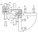
以下、本発明の実施例を図示した添付図面を参照して、本発明を詳細に説明する。なお、図面において、図1は本発明に係るレボルビング型自動巻取機の一実施例の正面図であり、図2および図3は、この実施例装置の初期糸掛け時を示す側面図であり、図2(a)は綾振り支点ガイドへ糸掛け時、図2(b)は初期糸掛けガイドへの糸掛け時を示す。図4は本発明に係る綾振り支点ガイドの一実施例の平面図であり、(a)は定常運転時、(b)は糸掛け時を示す。図5は本発明に係る綾振り支点ガイドの別の実施例の平面図であり、(a)は定常運転時、(b)は綾振りガイドを回動させている状態を示し、(c)は糸掛け時を示す。図6は図5に示す実施例の詳細平面図である。
【0032】
図1および図2において、紡糸機の紡糸口金(図示せず)から連続的に供給される複数本(本実施例では8本)の糸条Yを送給ローラR1、R2に巻掛けする。送給ローラR2の出口には複数本の糸条Yを所定の間隔に分離するための糸ガイドGが配設されている。
【0033】
送給ローラR2の下流には綾振り支点ガイド12、12′が配設されており、綾振り支点ガイド12、12′によって複数の糸条を巻取機Wに巻取られる複数のパッケージの間隔に規制している。
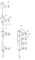
【0034】
図4は本発明に係る綾振り支点ガイドの一実施例の平面図であり、送給ローラR2の下流に水平に設置された綾振り支点ガイド移動装置(シャフト)11が後述するボビンホルダ4、5、4′、5′に平行に設けられ、シャフト11に沿って移動可能に複数個のブロック31が装着されている。各ブロック31からバー32がシャフト11に直交する方向に突設されており、各バー32には綾振り支点ガイド12、12′が並設されている。綾振り支点ガイド12、12′は、ブロック31とともにシャフト11に沿って軸方向に移動可能であり、定常運転時は図4(a)のように隣設する綾振り支点ガイド12および12′はシャフト11の軸方向に間隔を開けており、糸掛け時は図4(b)のようにブロック31が隣接している。
【0035】
図5および図6は本発明に係る綾振り支点ガイドの別の実施例の平面図であり、送給ローラR2の下流に水平に設置された綾振り支点ガイド移動装置(シャフト)11が同様にボビンホルダ4、5、4′、5′に平行に設けられ、シャフト11に沿って移動可能に複数個のブロック31が装着されている。図6に示すように、各ブロック31にバー32がピン33によって揺動可能に枢着されている。各バー32には綾振り支点ガイド12、12′が並設されている。更に、各ブロック31にプレート34がピン35(図6参照)によって揺動可能に枢着されている。シャフト11と平行にバー32を回動させるためのシャフト39が設けられ、このシャフト39には補助ブロック36が移動可能に装着されている。補助ブロック36はシャフトの軸線方向に所定の長さを有しており、図5(c)に示す糸掛け時にブロック31が所定の間隔となるようにしている。各プレート34にはその両端部近傍に2つの長穴34a、34bが形成されており、長穴34aに補助ブロック36に突設しているピン37が嵌合し、長穴34bにブロック36に突設しているピン38が嵌合している。
【0036】
シャフト39を軸方向に移動させることにより、プレート34をピン35の回りに揺動させることができ、プレート34の揺動により、綾振り支点ガイド12、12′を担持したバー32を図5(a)に示すようにシャフト11に直交する位置(定常運転位置)と、図5(c)に示すようにシャフト11に平行する位置(糸掛け位置)とすることができる。
【0037】
また、シャフト11を軸方向に移動させて、ブロック31が図5(a)に示すように軸方向に間隔を開けた位置(定常運転位置)と軸方向に互いに接近して補助ブロック36の長さにより規制される間隔となる位置(糸掛け位置)とを取れるようにしている。
【0038】
すなわち、シャフト11、39の操作により、ブロック31が図5(a)に示すように軸方向に間隔を開けるとともに綾振り支点ガイド12、12′を担持したバー32がシャフト11に直交する位置(定常運転位置)と、ブロック31が図5(c)に示すように補助ブロック36の長さにより規制される間隔に接近するとともに綾振り支点ガイド12、12′を担持したバー32がシャフト11に平行する位置(糸掛け位置)とを取れる
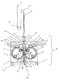
巻取機Wのユニットケース1の底部には前方(図2の左側)の作業スペース近傍まで延在するベース2が設けられている。ユニットケース1の前面には円板形状のターレットテーブル3、3′がその水平中心軸線回りに回動可能に設けられ、モータ等の駆動手段(図示せず)により、ターレットテーブル3は時計方向に、ターレットテーブル3′は反時計方向へと、互いに逆方向に回動される。
【0039】
ターレットテーブル3、3′には、図1の紙面に垂直な方向(図2の紙面方向)に、各2本のボビンホルダ4、5、4′、5′が回転可能に突設されている。ボビンホルダ4、5、4′、5′は駆動装置(図示せず)に連結されており、所定の速度で、2本のボビンホルダ4、5は時計方向に、他の2本のボビンホルダ4′、5′は反時計方向へ回転させられるようになっている。本実施例のボビンホルダ4、5、4′、5′にはそれぞれ8個のボビン6が装着される。
【0040】
本実施例では、ボビンホルダを直接電動機で駆動するようにしたスピンドル駆動巻取機について説明したが、本発明は接圧ローラを電動機で駆動し、接圧ローラにボビンホルダを圧接して駆動するようにしたフリクション駆動方式の巻取機であってもよい。
【0041】
ユニットケース1の内部に2本のスライドレール(図示せず)が垂直に取着され、スライドレールに沿って昇降枠8が流体シリンダ(図示せず)により昇降可能である。
【0042】
昇降枠8、8′には、ボビンホルダ4、5、4′、5′に装着されたボビン6またはその上に形成された糸層に接触する接圧ローラ9、9′および糸条Yをボビン6の軸方向に綾振るトラバース装置10が担持されている。なお、接圧ローラ9、9′は少なくとも一方が昇降枠8に対して独立して、揺動可能な状態で昇降枠8に支承されている。
【0043】
接圧ローラ9、9′は、ボビンホルダ4、5、4′、5′に装着されたボビン6に糸条Yを巻取る際に、糸条Yをボビン6へ送ると共にボビン6またはその上に形成された糸層を圧接して、パッケージの形状を良くするとともに、パッケージ硬度を高めることを目的としてパッケージ表面に接触させられている。
【0044】
実施例においては、2つの接圧ローラ9、9′の間に1つのトラバース装置10が設けられている。トラバース装置10は駆動装置(図示せず)により回転する円筒状のカム(図示せず)を有し、カムの溝に係合したトラバースガイドが左右に往復移動して、トラバースガイドに係合した糸条Yをトラバース範囲内でボビン6の軸方向に綾振る。
【0045】
なお、実施例ではカム式のトラバース装置を採用しているが、本発明においては回転ブレード方式のトラバース装置等としてもよい。
【0046】
本実施例においては、ボビンホルダ4、5、4′、5′と接触している接圧ローラ9、9′の中心が、一方のターレットテーブル3に突設した2本のボビンホルダ4、5の中心を結ぶ仮想線分cと、他方のターレットテーブル3′に突設した2本のボビンホルダ4′、5′の中心を結ぶ仮想線分c′との間に、位置するように構成している。
【0047】
本実施例においては、2つのターレットテーブルが糸道を挟んで配設され、一方のターレットテーブルに対して設置された接圧ローラと他方のターレットテーブルに対して設置された接圧ローラの回転方向が互いに逆とされているとともに、前記一方のターレットテーブルと他方のターレットテーブルの回動方向が互いに逆である。したがって、巻取機全体の機幅を小さくできる。このため巻取機の設置スペースが小さくなり、スペース効率が向上する。
【0048】
また、糸条切替開始時、すなわち、ターレットテーブルの回動開始時には、ターレットテーブルに加速度が掛かるので、この加速度によりボビンホルダが接圧ローラを押上げる傾向がある。これに対して、本発明においては、接圧ローラ9、9′をターレットテーブル3、3′と特別の幾何学な位置関係に配置、すなわち、ボビンホルダ4、5、4′、5′と接触している接圧ローラ9、9′の中心が、一方のターレットテーブル3に突設した2本のボビンホルダ4、5の中心を結ぶ仮想線分cと、他方のターレットテーブル3′に突設した2本のボビンホルダ4′、5′の中心を結ぶ仮想線分c′との間に、位置させている。この幾何学的な配置構成により、ターレットテーブル3、3′の回動開始時の加速度によりボビンホルダが接圧ローラを押上げることをなくすことができ、ボビンホルダが滑らかに回転することが可能となり、ターレットテーブル回動開始時のパッケージ表層の糸条の中寄りや接圧によるダメージを防止でき、糸条の品質を向上できる利点がある。
【0049】
更に、上述の幾何学的な配置構成に加えて、糸条巻取中の接圧ローラ9、9′の回転中心とボビンホルダ4、5の回転中心とを結ぶ仮想線分と垂直線dとの成す角度βを45度以下にすることによって、接圧ローラ9、9′の移動方向をほぼ垂直方向とすることができる。このため巻取機の機幅を小さくすることが可能となり、設置スペースの効率を向上させることができる。
【0050】
更に、それぞれの2本のボビンホルダ4、5、4′、5′の中心を結ぶ仮想線分c、c′が少なくとも糸条の巻始めにおいて「ハ」の字形状となるようにする。すなわち、空ボビン4、4′の間隔を、満巻きパッケージの径を装着したときの間隔Lよりも小さく、かつ、切替直後の満巻きパッケージが干渉しない状態の間隔より大きくすることによって、機幅を小さくすることが可能となる。
【0051】
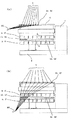
また、前述のように、トラバース装置の上方に綾振り支点ガイド移動装置11をボビンホルダに平行に略水平に設け、綾振り支点ガイド移動装置11にはボビンホルダ4、5、4′、5′に装着したボビン6、6′に対応して複数個の綾振り支点ガイド12、12′を配設している。
【0052】
綾振り支点ガイド12、12′は、ボビンホルダ4、5、4′、5′の軸方向に移動可能に構成されている。これにより、綾振り支点ガイド12、12′は、糸条巻取り時には、ボビンホルダ4、5、4′、5′に装着したボビン6上に巻取られるパッケージの中央に対応する位置に固定され、一方、糸条をボビンに糸掛けをする時には、ボビンホルダの先端側、すなわち、操作側へ移動する。
【0053】
更に、ユニットケース1の中央部下部に糸掛け装置14、14′の下端部14a、14′aが枢着されており、糸掛け装置14、14′は下端部14a、14′aの回りに揺動可能であり、ユニットケース1の中央部下方の復帰位置(図1)と、初期糸掛け時の作動位置(図4)との間を、シリンダ(図示せず)によっ移動する。
【0054】
すなわち、それぞれの巻取り側のボビンホルダ4、5に対応して糸掛け装置14、14′が配設されており、糸掛け装置14、14′は反下端部側先端に初期糸掛けガイド15、15′を具備している。糸掛け装置14、14′は、格納時には格納位置(図1)に格納され、糸掛け時には格納位置から糸掛け位置まで移動可能である。ここに格納位置は、ターレットテーブル3、3′の回動時に、それぞれに突設したボビンホルダに装着したボビンの外径が描く軌跡a、a′に挟まれた位置にある。一方、糸掛け位置は、コンタクトローラ9、9′とコンタクトローラ9、9′に接触して回転するボビン6の外径との接線b、b′を越える位置にあり、糸掛け位置においては複数の初期糸掛けガイド15、15′は互いに離間する方向に移動可能である。
【0055】
糸掛け装置14、14′は、ユニットケース1の前面から作業スペース近傍まで、ボビンホルダ4、5、4′、5′に平行に、図2の紙面に平行な方向に延在しており、初期糸掛け該と15、15′は流体圧シリンダ(図示せず)により糸掛け装置14、14′に沿って移動可能である。
【0056】
更に、ユニットケース1の中央部上部にL字状断面をしたプレート18、18′の一端部18a、18a′が枢着されており、プレート18、18′は一端部18a、18a′の回りに揺動可能となっている。プレート18、18′には、ボビン6の糸捕捉溝に糸条を案内する糸案内ガイド16、16′および所定量の糸条に巻かれている糸条が端面から落ちないように糸道を規制する糸道規制ガイド17、17′が取着されている。
【0057】
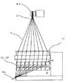
以下、この実施例装置の初期糸掛け時の作動について説明する。紡糸機の紡糸口金の下方で、糸条Yを吸引装置SGにより吸引しつつ、送給ローラR1、R2、糸ガイドGに糸掛けする。
【0058】
ついで、図4または図5に示すシャフト11を操作して、図2(a)に示すように、綾振り支点ガイド移動装置11の綾振り支点ガイド12、12′をそれぞれ(ボビンの中央に対応する位置から)糸掛け操作側へ移動する。この際に、図5に示す実施例においてはシャフト11とともにシャフト39を操作して、綾振り支点ガイド12、12′を図5(c)に示すようにシャフト11に平行させる。この状態で、綾振り支点ガイド12、12′に糸通しする。
【0059】
これら図4および図5に示した実施例装置では、ブロック31の片側から操作すればよく、サクションガンSGを大きく移動させることはなくなる。しかし、図4に示す実施例では、図4(b)に示すように、作業面側(ボビンホルダの先端側)から順番にバー32に奥側と手前側に並列に設置された綾振り支点ガイド12、12′に、交互に糸を掛ける必要がある。そのため、特に奥側の綾振り支点ガイド12′への糸掛け時には手前側の綾振り支点ガイド12が邪魔となることがある。また、狭いスペースで糸掛けを行うことになる。これらのため、糸掛けに時間が掛り、また、糸が手前側のガイドに接触する等による作業ミスに起因して断糸が多く発生し易いということが危惧されることがある。
【0060】
これに対して、図5に示す実施例においては、綾振り装置内部にリンク機構を設け、シャフト39を引くことによって、綾振り支点ガイドが90度回転し、軸方向に対し一列に配置しており、複数個の綾振り支点ガイド12、12′が、糸条巻取中は図5(a)に示すようにボビンホルダ4、5、4′、5′の軸方向に対して直交する方向に並列に配置されて複数のボビンホルダ4、5、4′、5′に糸条を同時に巻取るようにされているとともに、綾振り支点ガイド12、12′への糸掛け時には図5(c)に示すようにボビンホルダ4、5、4′、5′の軸方向に整列可能としており、糸掛けを容易に且つ迅速に行なえるようにしている。
【0061】
複数個の綾振り支点ガイド12、12′を、図2(a)に示すようにボビンホルダ4、5、4′、5′の軸方向に互いに接近させるとともに、図5(c)に示すようにボビンホルダ4、5、4′、5′の軸方向に整列させ、複数個の綾振り支点ガイド12、12′への糸掛けを行なう。次いで、シャフト11、39を移動させ、図2(b)および図5(a)に示すように、複数個の綾振り支点ガイド12、12′を定常位置とする。その後、ボビンホルダ4、4′に装着したボビン6、6′と接圧ローラ9、9′を接触させた後、初期糸掛けガイド15、15′を図2(a)、(b)に示す初期糸掛け位置に移動させる。次いで、初期糸掛けガイド15、15′に糸通しした後、吸引装置SGを、図2(b)、図3に示すように、巻取機作業側下方に位置させる。
【0062】
図3は、ボビンホルダ4、4′と接圧ローラ9、9′の回転を起動し、所定の回転数に到達して、これから初期の糸掛けを行う直前の状態を示している。図3に示すように、流体圧シリンダ(図示しない)により、初期糸掛けガイド15、15′をボビンホルダ4、4′に装着したボビン6に形成した糸捕捉溝に対応した位置に移動させる。
【0063】
次いで、糸掛け装置14、14′をシリンダ(図示せず)によって揺動させ、糸掛け装置14、14′を、コンタクトローラ9、9′の外周とボビン6,6′の外周を結んだ仮想線分b、b′を越える位置まで、流体圧シリンダ(図示しない)により、揺動させ、初期糸掛けガイド15、15′において屈曲した糸条をボビン6、6′に形成した糸捕捉溝に係合させ、糸条の巻取りを開始する。
【0064】
次いで、ボビンホルダに装着したボビンの外周が糸掛け装置14、14′に接触しないように、初期糸掛け装置14、14′を、ボビンホルダに装着したボビンの外径が描く軌跡a,a′の領域外へ復帰させる。
【0065】
【発明の効果】
本発明によれば、複数のボビンホルダに糸条を同時に巻取るようにした糸条巻取機において、複数個の綾振り支点ガイドがトラバース装置の上流位置においてボビンホルダの軸方向に対して直交する方向に並列に配置されており、綾振り支点ガイドへの糸掛け時にはブロックの片側から操作すればよく、サクションガンを大きく移動させる必要がなく、作業性が向上する。
【0066】
更に、本発明によれば、複数個の綾振り支点ガイドが、糸条巻取中はボビンホルダの軸方向に対して直交する方向に並列に配置されて複数のボビンホルダに糸条を同時に巻取るようにされているとともに、綾振り支点ガイドへの糸掛け時にはボビンホルダの軸方向に整列可能となる。そのため、特に奥側の綾振り支点ガイドへの糸掛け時には手前側の綾振り支点ガイドが邪魔となることがなく、充分に大きなスペースで糸掛けを行える。これらのため、糸掛けの時間がかからず、また、糸が手前側のガイドに接触する等による作業ミスもなくなり、断糸の発生も著しく減少する。
【0067】
更にまた、本発明によれば、綾振り支点ガイドへの糸掛け時には、複数個の綾振り支点ガイドがボビンホルダの軸方向に互いに接近可能である糸条の綾振り装置が提供され、糸掛け作業が一層容易に行なえる。
【0068】
特に実施例においては、綾振り支点ガイドが90度回転し、一列に配置できることにより、糸掛け時手前側の綾振り支点ガイドが邪魔とならず、糸掛け時間短縮及び作業ミスを減少させることが可能となる。
【図面の簡単な説明】
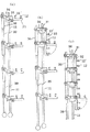
【図1】本発明に係るレボルビング型自動巻取機の一実施例の正面図である。
【図2】図1に示す実施例装置の初期糸掛け時を示す側面図であり、(a)は綾振り支点ガイドへ糸掛け時、(b)は初期糸掛けガイドへの糸掛け時を示す。
【図3】図1に示す実施例装置の初期糸掛け時を示す側面図である。
【図4】本発明に係る綾振り支点ガイドの一実施例の平面図であり、(a)は定常運転時、(b)は糸掛け時を示す。
【図5】本発明に係る綾振り支点ガイドの別の実施例の平面図であり、(a)は定常運転時、(b)は綾振りガイドを回動させている状態を示し、(c)は糸掛け時を示す。
【図6】図5に示す実施例の詳細平面図である。
【図7】従来の綾振り支点ガイドの平面図であり、(a)は定常運転時、(b)は糸掛け時を示す。
【符号の説明】
3、3′ ターレットテーブル
4、5、4′、5′ ボビンホルダ
8 昇降枠
9、9′ 接圧ローラ
12、12′ 綾振り支点ガイド
14、14′ 糸掛け装置
15、15′ 初期糸掛けガイド
16、16′ 糸案内ガイド
17、17′ 糸道規制ガイド
18、18′ プレート
30、30′ トラバース装置
a、a′ ボビンホルダに装着したボビンの外径が描く軌跡
b、b′ 接圧ローラとそれに接触して回転するボビンの外径との接線
c、c′ ボビンホルダの中心を結ぶ仮想線分[0001]
[Industrial applications]
The present invention relates to a yarn winding machine that winds a yarn on a plurality of bobbin holders at the same time. More specifically, the present invention provides a turret table rotatably in a unit case, rotatably supports a plurality of bobbin holders for mounting a bobbin for winding a yarn on the turret table, and winding the bobbin holder on one bobbin holder. When the amount of the thread reaches a predetermined amount, the bobbin is switched to the bobbin mounted on the other bobbin holder, and a plurality of revolving type automatic winding machines configured to wind the thread are arranged side by side, and the thread is simultaneously moved to the plurality of bobbin holders. The present invention relates to a yarn winding machine adapted to be wound.
[0002]
[Prior art]
Generally, when a yarn spun from a spinneret of a spinning machine is continuously wound, a turret table rotatably mounted on a unit case and a turret table rotatably supported on the turret table, for winding the yarn. Two bobbin holders for mounting bobbins, a movable frame vertically moving up and down, a contact pressure roller rotatably attached to the movable frame, and an upstream side of the contact pressure roller as viewed in the yarn thread direction. A revolving-type yarn winding machine constituted by a traverse device located is used.
[0003]
As a configuration of such a conventional yarn winding machine, there is a structure in which two winding machines are arranged adjacent to each other, the yarn is separated from an upstream feed roller, and the yarn is wound on the two winding machines. Was.
[0004]
As another conventional technique, Patent Document 1 (Japanese Patent Application Laid-Open No. 1-267270) discloses a technique in which a plurality of turret tables are vertically arranged in one machine frame.
[0005]
As still another conventional technique, Patent Document 2 (Japanese Patent Application Laid-Open No. 2002-515388) discloses that two turret tables are vertically arranged in one machine frame, and units constituted by these are symmetrically arranged. Is disclosed.
[0006]
In recent years, there has been a tendency to increase the number of ends of a yarn winding machine in order to increase the amount of production. In this case, it is required to improve the space efficiency per production amount, reduce the equipment cost, improve the threading efficiency, and improve the winding shape.
[0007]
In response to this request, the conventional device described first has a configuration in which two winders are arranged in parallel, so that the interval between the yarns entering the two winders increases. The angle α between the two yarns coming out of the feed roller becomes large. As a result, there has been a problem that the contact angle between the yarn and the guide G is increased, the frictional resistance is increased, and the yarn is fluffed.
[0008]
As a countermeasure, if the contact angle between the yarn and the guide G is reduced, the position of the feed roller is increased, and there is a problem that operability is deteriorated.
[0009]
In the conventional apparatus disclosed in
[0010]
Further, in the conventional device disclosed in
[0011]
The winding device is disposed vertically and symmetrically left and right. For this reason, at the time of yarn winding, in order to avoid interference between the yarn and the winder portion, it is necessary to carry out the yarn winding one by one from the upper or lower winder while sucking a plurality of yarns. Was. As a result, the time required for threading became long, the amount of waste thread increased, and the efficiency became poor.
[0012]
Even when the yarn is hooked on the left and right winding devices, the contact roller and the bobbin holder are in contact in a state where they are lined up in the horizontal direction. However, there was a problem that the threading success rate was reduced.
[0013]
Further, as the contact pressure roller retreats in the horizontal direction as the yarn becomes thicker, the width of the winding machine is increased, and the efficiency of the installation space is significantly deteriorated.
[0014]
In view of the above-mentioned problems associated with the prior art, the present applicant provides a multi-end revolving type automatic winder having good operability, high yarn threading properties, and high space efficiency. For this purpose, Patent Document 3 (Japanese Patent Application No. 2002-33760) has been proposed.
[0015]
In
[0016]
Further, the present applicant has proposed Patent Document 4 (Japanese Patent Application No. 2002-239860). In this
[0017]
[Patent Document 1] Japanese Patent Application Laid-Open No. 1-267270
[Patent Document 2] JP-T-2002-515388
[Patent Document 3] Japanese Patent Application No. 2002-33760
[0020]
[Patent Document 4] Japanese Patent Application No. 2002-239860
[0021]
[Problems to be solved by the invention]
Although the details of the traverse fulcrum guide are not disclosed in the yarn winder of the type disclosed in
[0022]
However, in such an apparatus, as shown in FIG. 7B, the
[0023]
[Means for Solving the Problems]
As a countermeasure, as shown in FIG. 4, a bar is protruded only on one side of the block parallel to the bobbin holder at the upstream position of the traverse device, and the back side of the bar (near the block) and the front side (from the block). It is conceivable to install a plurality of traverse fulcrum guides in parallel with the distant side).
[0024]
That is, according to the present invention, in the yarn winding machine configured to simultaneously wind the yarn on the plurality of bobbin holders, the plurality of traverse fulcrum guides are orthogonal to the axial direction of the bobbin holder at the upstream position of the traverse device. A yarn traversing device is provided, wherein the yarn traversing device is arranged in parallel in a direction in which the yarn is traversed.
[0025]
In the present specification, the “direction orthogonal to the axial direction of the bobbin holder” includes not only a direction forming an angle of 90 ° with the axial direction of the bobbin holder, but also a direction substantially or substantially 90 ° from the axial direction of the bobbin holder. It also includes directions making angles.
[0026]
In such an apparatus, the operation can be performed from one side of the block, and the suction gun does not need to be largely moved. However, it is necessary to alternately thread the traverse fulcrum guides installed in parallel on the back side and the near side of the bar in order from the work surface side (tip end of the bobbin holder). For this reason, the traverse fulcrum guide on the front side may be an obstacle particularly when the yarn is hooked on the traverse fulcrum guide on the back side. In addition, the thread is hooked in a narrow space. For these reasons, it may take a long time to hook the thread, and there is a concern that a large number of thread breaks are likely to occur due to a work error caused by the thread coming into contact with the guide on the near side.
[0027]
As a countermeasure, in the present invention, the plurality of traverse fulcrum guides are arranged in parallel in a direction orthogonal to the axial direction of the bobbin holder during winding of the yarn, and the yarn is wound around the plurality of bobbin holders simultaneously. A yarn traversing device is provided which is adapted to take up the traverse fulcrum guide so that the traverse fulcrum guide can be aligned in the axial direction of the bobbin holder when the yarn is hooked on the traverse fulcrum guide.
[0028]
More specifically, as shown in the embodiment, by providing a link mechanism inside the traverse device and pulling the shaft, the traverse fulcrum guide rotates 90 degrees and is arranged in a line in the axial direction. Is preferred.
[0029]
Furthermore, according to the present invention, there is provided a yarn traversing device in which the plurality of traverse fulcrum guides can approach each other in the axial direction of the bobbin holder when the yarn is hooked on the traverse fulcrum guide.
[0030]
That is, as shown in the embodiment, the traverse device is provided with a slide mechanism, and by further pulling the shaft. It is preferable that the traverse fulcrum guide can be drawn forward.
[0031]
BEST MODE FOR CARRYING OUT THE INVENTION
Hereinafter, the present invention will be described in detail with reference to the accompanying drawings illustrating embodiments of the present invention. In the drawings, FIG. 1 is a front view of one embodiment of a revolving type automatic winder according to the present invention, and FIGS. 2 and 3 are side views showing an initial threading state of the embodiment device. FIG. 2A shows a state in which the thread is hooked on the traverse fulcrum guide, and FIG. 2B shows a state in which the thread is hooked on the initial threading guide. 4A and 4B are plan views of one embodiment of the traverse fulcrum guide according to the present invention, in which FIG. 4A shows a steady operation and FIG. 5A and 5B are plan views of another embodiment of the traverse fulcrum guide according to the present invention. FIG. 5A shows a state in which the traverse guide is rotated during a steady operation, and FIG. Indicates the time of threading. FIG. 6 is a detailed plan view of the embodiment shown in FIG.
[0032]
1 and 2, a plurality (eight in this embodiment) of yarns Y continuously supplied from a spinneret (not shown) of a spinning machine are wound around feed rollers R1 and R2. A yarn guide G for separating a plurality of yarns Y at predetermined intervals is provided at an outlet of the feed roller R2.
[0033]
Downstream of the feed roller R2, traverse fulcrum guides 12 and 12 'are provided, and the interval between a plurality of packages in which a plurality of yarns are wound by the traverse fulcrum guides 12 and 12' on the winding machine W. Is regulated.
[0034]
FIG. 4 is a plan view of one embodiment of the traverse fulcrum guide according to the present invention, in which a traverse fulcrum guide moving device (shaft) 11 horizontally installed downstream of the feed roller R2 is provided with
[0035]
FIGS. 5 and 6 are plan views of another embodiment of the traverse fulcrum guide according to the present invention, in which a traverse fulcrum guide moving device (shaft) 11 horizontally installed downstream of the feed roller R2 is similarly mounted. A plurality of
[0036]
By moving the
[0037]
Further, the
[0038]
That is, by operating the
[0039]
The turret tables 3, 3 'are provided with two
[0040]
In the present embodiment, the spindle drive winder in which the bobbin holder is directly driven by the electric motor has been described.However, the present invention drives the contact pressure roller by the electric motor, and presses and drives the bobbin holder to the contact pressure roller. It may be a friction drive type winder as described above.
[0041]
Two slide rails (not shown) are vertically mounted inside the
[0042]
The lifting frames 8, 8 'are provided with
[0043]
When the yarn Y is wound around the
[0044]
In the embodiment, one
[0045]
Although a cam type traverse device is employed in the embodiment, a rotary blade type traverse device may be used in the present invention.
[0046]
In the present embodiment, the centers of the
[0047]
In the present embodiment, two turret tables are disposed with the yarn path interposed therebetween, and the rotation direction of the contact pressure roller provided for one turret table and the contact pressure roller provided for the other turret table Are opposite to each other, and the rotating directions of the one turret table and the other turret table are opposite to each other. Therefore, the machine width of the entire winder can be reduced. For this reason, the installation space of the winder is reduced, and the space efficiency is improved.
[0048]
Further, when the yarn switching is started, that is, when the rotation of the turret table is started, acceleration is applied to the turret table, and the bobbin holder tends to push up the contact pressure roller due to the acceleration. On the other hand, in the present invention, the
[0049]
Further, in addition to the above-described geometric arrangement, a vertical line d and an imaginary line connecting the rotation centers of the
[0050]
Furthermore, the imaginary line segments c and c 'connecting the centers of the two
[0051]
Further, as described above, the traverse fulcrum
[0052]
The traverse fulcrum guides 12 and 12 'are configured to be movable in the axial direction of the
[0053]
Further, the lower ends 14a, 14'a of the
[0054]
That is, the
[0055]
The
[0056]
Further, one ends 18a, 18a 'of
[0057]
Hereinafter, the operation of this embodiment device at the time of initial threading will be described. The yarn Y is hooked on the feed rollers R1 and R2 and the yarn guide G while the yarn Y is sucked by the suction device SG below the spinneret of the spinning machine.
[0058]
Next, the
[0059]
In the embodiment shown in FIGS. 4 and 5, the operation can be performed from one side of the
[0060]
On the other hand, in the embodiment shown in FIG. 5, a link mechanism is provided inside the traverse device, and by pulling the
[0061]
A plurality of traverse fulcrum guides 12 and 12 'are made to approach each other in the axial direction of the
[0062]
FIG. 3 shows a state in which the rotations of the
[0063]
Next, the
[0064]
Next, the
[0065]
【The invention's effect】
According to the present invention, in a yarn winding machine configured to simultaneously wind yarn on a plurality of bobbin holders, a plurality of traverse fulcrum guides are arranged in a direction orthogonal to an axial direction of the bobbin holder at an upstream position of the traverse device. When the yarn is hooked on the traversing fulcrum guide, it is sufficient to operate from one side of the block, and it is not necessary to largely move the suction gun, thereby improving workability.
[0066]
Further, according to the present invention, a plurality of traverse fulcrum guides are arranged in parallel in a direction orthogonal to the axial direction of the bobbin holder during winding of the yarn, so that the yarn is wound on the plurality of bobbin holders simultaneously. When the yarn is hooked on the traverse fulcrum guide, the bobbin holder can be aligned in the axial direction. Therefore, especially when the yarn is hooked on the traverse fulcrum guide on the back side, the traverse fulcrum guide on the front side does not become an obstacle, and the yarn can be hooked in a sufficiently large space. For these reasons, no time is required for threading, and there is no work error due to the thread coming into contact with the guide on the near side, and the occurrence of thread breakage is significantly reduced.
[0067]
Still further, according to the present invention, there is provided a yarn traversing device in which a plurality of traverse fulcrum guides can approach each other in the axial direction of the bobbin holder when the yarn is hooked on the traverse fulcrum guide. Can be performed more easily.
[0068]
In particular, in the embodiment, since the traverse fulcrum guide is rotated 90 degrees and can be arranged in a line, the traverse fulcrum guide on the front side at the time of threading does not become an obstacle, and it is possible to reduce the threading time and reduce operation errors. It becomes possible.
[Brief description of the drawings]
FIG. 1 is a front view of an embodiment of a revolving type automatic winder according to the present invention.
FIGS. 2A and 2B are side views showing an initial threading state of the embodiment apparatus shown in FIG. 1, wherein FIG. 2A shows a state of threading on a traverse fulcrum guide, and FIG. Show.
FIG. 3 is a side view showing the apparatus shown in FIG. 1 at the time of initial threading.
FIGS. 4A and 4B are plan views of one embodiment of a traverse fulcrum guide according to the present invention, wherein FIG.
FIGS. 5A and 5B are plan views of another embodiment of the traverse fulcrum guide according to the present invention, wherein FIG. 5A shows a state of steady operation, FIG. ) Indicates the time of threading.
FIG. 6 is a detailed plan view of the embodiment shown in FIG. 5;
FIGS. 7A and 7B are plan views of a conventional traverse fulcrum guide, where FIG. 7A shows a normal operation and FIG.
[Explanation of symbols]
3, 3 'Turret table 4, 5, 4', 5 'Bobbin holder 8
Claims (3)
Priority Applications (7)
| Application Number | Priority Date | Filing Date | Title |
|---|---|---|---|
| JP2002269586A JP4176428B2 (en) | 2002-09-17 | 2002-09-17 | Traverse device |
| DE10393262.3T DE10393262B4 (en) | 2002-09-17 | 2003-08-19 | thread guide |
| AU2003262249A AU2003262249A1 (en) | 2002-09-17 | 2003-08-19 | Traverse motion device |
| TR2005/00921T TR200500921T2 (en) | 2002-09-17 | 2003-08-19 | Carriage assembly |
| CNB038220644A CN100404401C (en) | 2002-09-17 | 2003-08-19 | traverse device |
| PCT/JP2003/010464 WO2004026746A1 (en) | 2002-09-17 | 2003-08-19 | Traverse motion device |
| US11/083,191 US20050161550A1 (en) | 2002-09-17 | 2005-03-17 | Traverse apparatus |
Applications Claiming Priority (1)
| Application Number | Priority Date | Filing Date | Title |
|---|---|---|---|
| JP2002269586A JP4176428B2 (en) | 2002-09-17 | 2002-09-17 | Traverse device |
Publications (2)
| Publication Number | Publication Date |
|---|---|
| JP2004106972A true JP2004106972A (en) | 2004-04-08 |
| JP4176428B2 JP4176428B2 (en) | 2008-11-05 |
Family
ID=32024814
Family Applications (1)
| Application Number | Title | Priority Date | Filing Date |
|---|---|---|---|
| JP2002269586A Expired - Lifetime JP4176428B2 (en) | 2002-09-17 | 2002-09-17 | Traverse device |
Country Status (7)
| Country | Link |
|---|---|
| US (1) | US20050161550A1 (en) |
| JP (1) | JP4176428B2 (en) |
| CN (1) | CN100404401C (en) |
| AU (1) | AU2003262249A1 (en) |
| DE (1) | DE10393262B4 (en) |
| TR (1) | TR200500921T2 (en) |
| WO (1) | WO2004026746A1 (en) |
Cited By (8)
| Publication number | Priority date | Publication date | Assignee | Title |
|---|---|---|---|---|
| CN102330163A (en) * | 2010-07-13 | 2012-01-25 | 日本Tmt机械株式会社 | Spinning winding device |
| JP2012188784A (en) * | 2011-03-11 | 2012-10-04 | Tmt Machinery Inc | Spinning winder |
| JP2013023787A (en) * | 2011-07-22 | 2013-02-04 | Tmt Machinery Inc | Spinning winder |
| JP2013234047A (en) * | 2012-05-09 | 2013-11-21 | Tmt Machinery Inc | Yarn winding apparatus |
| JP2015165060A (en) * | 2014-02-10 | 2015-09-17 | Tmtマシナリー株式会社 | Spinning takeoff device |
| JP2023091957A (en) * | 2021-12-21 | 2023-07-03 | Tmtマシナリー株式会社 | Yarn winding machine |
| JP2023101468A (en) * | 2022-01-08 | 2023-07-21 | エーリコン テクスティル ゲゼルシャフト ミット ベシュレンクテル ハフツング ウント コンパニー コマンディートゲゼルシャフト | Yarn splicing device for splicing melt-spun yarn |
| JP2023101467A (en) * | 2022-01-08 | 2023-07-21 | エーリコン テクスティル ゲゼルシャフト ミット ベシュレンクテル ハフツング ウント コンパニー コマンディートゲゼルシャフト | Yarn splicing device for splicing melt-spun yarn |
Families Citing this family (16)
| Publication number | Priority date | Publication date | Assignee | Title |
|---|---|---|---|---|
| ATE518026T1 (en) | 2004-11-10 | 2011-08-15 | Karl Mayer Textilmaschinen Ag | METHOD AND DEVICE FOR WINDING A TAPE CONSISTING OF A PLURALITY OF PARALLEL THREADS ON A DRUM ROTATING AROUND AN AXIS OF ROTATION |
| EP1657329A1 (en) * | 2004-11-10 | 2006-05-17 | Benninger AG | Method and device for winding a band of parallel yarns on a rotating drum |
| ITRM20070043A1 (en) * | 2007-01-30 | 2008-07-31 | Bromas S R L | MACHINE FOR AUTOMATIC ORDERING WITH SAMPLES WITH MULTIFILED AUTOMATED SYSTEM AND RELATIVE METHOD. |
| DE102010033579A1 (en) | 2010-08-05 | 2012-02-09 | Oerlikon Textile Gmbh & Co. Kg | Apparatus for winding synthetic yarns in a melt spinning process, has godet unit and two mirror-symmetrically arranged indexed winding stations, where godet unit has guide shell oriented transverse to winding spindles |
| DE102011114312A1 (en) | 2010-11-03 | 2012-05-03 | Oerlikon Textile Gmbh & Co. Kg | Device for winding of synthetic thread during melt-spinning process, for use in winding machine, has deflection rollers that are adjustably arranged transverse to spindles and are pivotable between angular positions |
| JP6211379B2 (en) | 2013-10-16 | 2017-10-11 | Tmtマシナリー株式会社 | Spinning winder |
| CN104960981B (en) * | 2015-04-14 | 2017-11-03 | 郑州中远氨纶工程技术有限公司 | Elastomeric yarn coiler device and elastomeric yarn switching method for winding |
| DE112016002122A5 (en) * | 2015-05-12 | 2018-01-25 | Oerlikon Textile Gmbh & Co. Kg | winding machine |
| WO2018100142A1 (en) * | 2016-12-02 | 2018-06-07 | Oerlikon Textile Gmbh & Co. Kg | Method and device for creating a plurality of synthetic threads on a winding machine |
| CN106494944B (en) * | 2016-12-16 | 2019-05-17 | 芜湖航达网业有限公司 | A kind of papermaking flat filament net line concentrator |
| CN106744015A (en) * | 2016-12-23 | 2017-05-31 | 芜湖航达网业有限公司 | A kind of polyester capillaries line concentrator |
| CN107472991B (en) * | 2017-07-17 | 2023-07-07 | 苏州金纬化纤装备有限公司 | Traversing device of yarn winder |
| CN109052029A (en) * | 2018-09-12 | 2018-12-21 | 澳洋集团有限公司 | A kind of yarn carrier of spinning machine |
| EP3838384A1 (en) * | 2019-12-21 | 2021-06-23 | Gambro Lundia AB | Fiber bundle handover |
| CN112209166A (en) * | 2020-10-09 | 2021-01-12 | 诸暨市思艺纺织有限公司 | Production process and equipment of large-circle bread yarn |
| JP7759763B2 (en) * | 2021-10-21 | 2025-10-24 | Tmtマシナリー株式会社 | Yarn threading unit and blended yarn manufacturing device |
Citations (6)
| Publication number | Priority date | Publication date | Assignee | Title |
|---|---|---|---|---|
| JPS59159668U (en) * | 1983-04-11 | 1984-10-26 | 帝人製機株式会社 | Multi-thread sorting thread guide |
| JPS61291377A (en) * | 1985-06-18 | 1986-12-22 | Toyobo Co Ltd | Multi-yarn guiding device |
| JPH01267270A (en) * | 1988-04-16 | 1989-10-25 | Teijin Seiki Co Ltd | Turret type automatic switching yarn winding machine |
| JPH0136840Y2 (en) * | 1985-06-18 | 1989-11-08 | ||
| JPH032789B2 (en) * | 1983-05-26 | 1991-01-16 | Teijin Seiki Co Ltd | |
| JP2002515388A (en) * | 1997-10-06 | 2002-05-28 | イー・アイ・デュポン・ドウ・ヌムール・アンド・カンパニー | Winder for synthetic filament |
Family Cites Families (13)
| Publication number | Priority date | Publication date | Assignee | Title |
|---|---|---|---|---|
| US4465242A (en) * | 1980-10-31 | 1984-08-14 | Rieter Machine Works Ltd. | Method and apparatus for inserting threads and similar items into a winding device |
| DE3170533D1 (en) * | 1980-10-31 | 1985-06-20 | Rieter Ag Maschf | Method and device for introducing yarns and the like in a winding machine |
| FR2585375B1 (en) * | 1985-07-25 | 1988-04-08 | Saint Gobain Vetrotex | DEVICE AND METHOD FOR SIMULTANEOUSLY WINDING SEPARATE THREADS ON A ROTATING MEDIUM |
| DE3619286A1 (en) * | 1986-06-07 | 1987-12-10 | Neumuenster Masch App | DEVICE FOR SIMULTANEOUSLY REWINDING SEVERAL THREADS |
| JPS6436840A (en) * | 1987-07-31 | 1989-02-07 | Kajima Corp | Elastic and plastic damper |
| DE59008918D1 (en) * | 1989-07-24 | 1995-05-24 | Rieter Ag Maschf | Thread changing system for winding machines. |
| US5054705A (en) * | 1990-05-04 | 1991-10-08 | Owens-Corning Fiberglas Corporation | Reciprocating strand guide for split strand roving packages |
| JPH04201946A (en) * | 1990-11-29 | 1992-07-22 | Howa Mach Ltd | Creel for spinning frame |
| DE19827635A1 (en) * | 1998-06-20 | 1999-12-23 | Iwka Industrieanlagen Gmbh | Assembly to lay a number of continuous yarns at the bobbin sleeves in a winder |
| JP2000327228A (en) * | 1999-05-14 | 2000-11-28 | Teijin Seiki Co Ltd | Threading device for winding machine |
| JP4128367B2 (en) | 2002-02-12 | 2008-07-30 | Tstm株式会社 | Revolving type automatic winder |
| JP4128412B2 (en) | 2002-08-20 | 2008-07-30 | Tstm株式会社 | Revolving type yarn winding machine |
| DE102005001000A1 (en) * | 2004-02-06 | 2005-08-25 | Saurer Gmbh & Co. Kg | Wind-up machinery for groups of filaments has two winding machines whose spools in each case are supplied with filament groups by adjacent guides on guide strip |
-
2002
- 2002-09-17 JP JP2002269586A patent/JP4176428B2/en not_active Expired - Lifetime
-
2003
- 2003-08-19 AU AU2003262249A patent/AU2003262249A1/en not_active Abandoned
- 2003-08-19 CN CNB038220644A patent/CN100404401C/en not_active Expired - Lifetime
- 2003-08-19 DE DE10393262.3T patent/DE10393262B4/en not_active Expired - Lifetime
- 2003-08-19 WO PCT/JP2003/010464 patent/WO2004026746A1/en not_active Ceased
- 2003-08-19 TR TR2005/00921T patent/TR200500921T2/en unknown
-
2005
- 2005-03-17 US US11/083,191 patent/US20050161550A1/en not_active Abandoned
Patent Citations (6)
| Publication number | Priority date | Publication date | Assignee | Title |
|---|---|---|---|---|
| JPS59159668U (en) * | 1983-04-11 | 1984-10-26 | 帝人製機株式会社 | Multi-thread sorting thread guide |
| JPH032789B2 (en) * | 1983-05-26 | 1991-01-16 | Teijin Seiki Co Ltd | |
| JPS61291377A (en) * | 1985-06-18 | 1986-12-22 | Toyobo Co Ltd | Multi-yarn guiding device |
| JPH0136840Y2 (en) * | 1985-06-18 | 1989-11-08 | ||
| JPH01267270A (en) * | 1988-04-16 | 1989-10-25 | Teijin Seiki Co Ltd | Turret type automatic switching yarn winding machine |
| JP2002515388A (en) * | 1997-10-06 | 2002-05-28 | イー・アイ・デュポン・ドウ・ヌムール・アンド・カンパニー | Winder for synthetic filament |
Cited By (12)
| Publication number | Priority date | Publication date | Assignee | Title |
|---|---|---|---|---|
| CN102330163A (en) * | 2010-07-13 | 2012-01-25 | 日本Tmt机械株式会社 | Spinning winding device |
| JP2012021241A (en) * | 2010-07-13 | 2012-02-02 | Tmt Machinery Inc | Spinning and winding apparatus |
| JP2012188784A (en) * | 2011-03-11 | 2012-10-04 | Tmt Machinery Inc | Spinning winder |
| JP2013023787A (en) * | 2011-07-22 | 2013-02-04 | Tmt Machinery Inc | Spinning winder |
| JP2013234047A (en) * | 2012-05-09 | 2013-11-21 | Tmt Machinery Inc | Yarn winding apparatus |
| JP2015165060A (en) * | 2014-02-10 | 2015-09-17 | Tmtマシナリー株式会社 | Spinning takeoff device |
| JP2023091957A (en) * | 2021-12-21 | 2023-07-03 | Tmtマシナリー株式会社 | Yarn winding machine |
| JP7793361B2 (en) | 2021-12-21 | 2026-01-05 | Tmtマシナリー株式会社 | Yarn winding machine |
| JP2023101468A (en) * | 2022-01-08 | 2023-07-21 | エーリコン テクスティル ゲゼルシャフト ミット ベシュレンクテル ハフツング ウント コンパニー コマンディートゲゼルシャフト | Yarn splicing device for splicing melt-spun yarn |
| JP2023101467A (en) * | 2022-01-08 | 2023-07-21 | エーリコン テクスティル ゲゼルシャフト ミット ベシュレンクテル ハフツング ウント コンパニー コマンディートゲゼルシャフト | Yarn splicing device for splicing melt-spun yarn |
| JP7553616B2 (en) | 2022-01-08 | 2024-09-18 | エーリコン テクスティル ゲゼルシャフト ミット ベシュレンクテル ハフツング ウント コンパニー コマンディートゲゼルシャフト | A threading device for threading melt-spun yarn |
| JP7624463B2 (en) | 2022-01-08 | 2025-01-30 | エーリコン テクスティル ゲゼルシャフト ミット ベシュレンクテル ハフツング ウント コンパニー コマンディートゲゼルシャフト | A threading device for threading melt-spun yarn |
Also Published As
| Publication number | Publication date |
|---|---|
| AU2003262249A1 (en) | 2004-04-08 |
| TR200500921T2 (en) | 2005-10-21 |
| US20050161550A1 (en) | 2005-07-28 |
| DE10393262B4 (en) | 2020-01-02 |
| WO2004026746A1 (en) | 2004-04-01 |
| CN100404401C (en) | 2008-07-23 |
| DE10393262T5 (en) | 2005-08-18 |
| CN1688500A (en) | 2005-10-26 |
| JP4176428B2 (en) | 2008-11-05 |
Similar Documents
| Publication | Publication Date | Title |
|---|---|---|
| JP4176428B2 (en) | Traverse device | |
| JP4128412B2 (en) | Revolving type yarn winding machine | |
| JP4128367B2 (en) | Revolving type automatic winder | |
| JP5615743B2 (en) | Spinning winder | |
| JP6275972B2 (en) | Textile machinery | |
| EP2366650B1 (en) | Yarn winding machine | |
| JP2015040116A5 (en) | ||
| JP5545593B2 (en) | Yarn winding machine | |
| JP2008290835A (en) | Yarn winding machine | |
| JP4074545B2 (en) | Yarn guide device for revolving type automatic winder | |
| US5318232A (en) | Method and apparatus for transferring a thread from a full package to an empty tube | |
| JP4612673B2 (en) | Winding device | |
| JP2008063148A (en) | Revolving automatic winder | |
| JP3680589B2 (en) | Synthetic fiber winding device and winding method | |
| CN1044630A (en) | Yarn winding apparatus and method | |
| CN222540106U (en) | A winding device with multiple winding positions | |
| JP3440839B2 (en) | Threading method of spinning winder | |
| JP2024126517A (en) | Yarn Winding Machine | |
| JP2005132603A (en) | Revolving type bobbin winding device and revolving type bobbin winding method | |
| JP2025149955A (en) | Winding device with multiple winding positions | |
| CN118978063A (en) | A textile equipment | |
| JPH08192959A (en) | Winding machine and its bobbin position controlling method | |
| CN118978065A (en) | Automatic bobbin anti-winding device and textile equipment | |
| KR20230139318A (en) | Yarn Winding Machine |
Legal Events
| Date | Code | Title | Description |
|---|---|---|---|
| A621 | Written request for application examination |
Free format text: JAPANESE INTERMEDIATE CODE: A621 Effective date: 20050214 |
|
| A131 | Notification of reasons for refusal |
Free format text: JAPANESE INTERMEDIATE CODE: A131 Effective date: 20080115 |
|
| A521 | Request for written amendment filed |
Free format text: JAPANESE INTERMEDIATE CODE: A821 Effective date: 20080307 Free format text: JAPANESE INTERMEDIATE CODE: A523 Effective date: 20080307 |
|
| TRDD | Decision of grant or rejection written | ||
| A01 | Written decision to grant a patent or to grant a registration (utility model) |
Free format text: JAPANESE INTERMEDIATE CODE: A01 Effective date: 20080819 |
|
| A01 | Written decision to grant a patent or to grant a registration (utility model) |
Free format text: JAPANESE INTERMEDIATE CODE: A01 |
|
| A61 | First payment of annual fees (during grant procedure) |
Free format text: JAPANESE INTERMEDIATE CODE: A61 Effective date: 20080820 |
|
| FPAY | Renewal fee payment (event date is renewal date of database) |
Free format text: PAYMENT UNTIL: 20110829 Year of fee payment: 3 |
|
| R150 | Certificate of patent or registration of utility model |
Ref document number: 4176428 Country of ref document: JP Free format text: JAPANESE INTERMEDIATE CODE: R150 Free format text: JAPANESE INTERMEDIATE CODE: R150 |
|
| FPAY | Renewal fee payment (event date is renewal date of database) |
Free format text: PAYMENT UNTIL: 20110829 Year of fee payment: 3 |
|
| S111 | Request for change of ownership or part of ownership |
Free format text: JAPANESE INTERMEDIATE CODE: R313113 |
|
| FPAY | Renewal fee payment (event date is renewal date of database) |
Free format text: PAYMENT UNTIL: 20110829 Year of fee payment: 3 |
|
| R350 | Written notification of registration of transfer |
Free format text: JAPANESE INTERMEDIATE CODE: R350 |
|
| FPAY | Renewal fee payment (event date is renewal date of database) |
Free format text: PAYMENT UNTIL: 20110829 Year of fee payment: 3 |
|
| FPAY | Renewal fee payment (event date is renewal date of database) |
Free format text: PAYMENT UNTIL: 20120829 Year of fee payment: 4 |
|
| R250 | Receipt of annual fees |
Free format text: JAPANESE INTERMEDIATE CODE: R250 |
|
| FPAY | Renewal fee payment (event date is renewal date of database) |
Free format text: PAYMENT UNTIL: 20120829 Year of fee payment: 4 |
|
| FPAY | Renewal fee payment (event date is renewal date of database) |
Free format text: PAYMENT UNTIL: 20130829 Year of fee payment: 5 |
|
| R250 | Receipt of annual fees |
Free format text: JAPANESE INTERMEDIATE CODE: R250 |
|
| R250 | Receipt of annual fees |
Free format text: JAPANESE INTERMEDIATE CODE: R250 |
|
| R250 | Receipt of annual fees |
Free format text: JAPANESE INTERMEDIATE CODE: R250 |
|
| R250 | Receipt of annual fees |
Free format text: JAPANESE INTERMEDIATE CODE: R250 |
|
| R250 | Receipt of annual fees |
Free format text: JAPANESE INTERMEDIATE CODE: R250 |
|
| R250 | Receipt of annual fees |
Free format text: JAPANESE INTERMEDIATE CODE: R250 |
|
| R250 | Receipt of annual fees |
Free format text: JAPANESE INTERMEDIATE CODE: R250 |
|
| R250 | Receipt of annual fees |
Free format text: JAPANESE INTERMEDIATE CODE: R250 |
|
| R250 | Receipt of annual fees |
Free format text: JAPANESE INTERMEDIATE CODE: R250 |
|
| R250 | Receipt of annual fees |
Free format text: JAPANESE INTERMEDIATE CODE: R250 |
|
| R250 | Receipt of annual fees |
Free format text: JAPANESE INTERMEDIATE CODE: R250 |
|
| EXPY | Cancellation because of completion of term |