【書類名】 明細書
【発明の名称】管継手
【特許請求の範囲】
【請求項1】
ソケット及び該ソケットに挿入連結されるプラグを有する管継手におけるソケットにおいて、
導管接続用の第1端部と、プラグ接続用の第2端部とを有する流体通路と、
該流体通路内に設けられ、同流体通路の第1端部側と第2端部側の間の流体の流れを許容する開位置と、流体の流れを阻止する閉位置との間で可動とされた開閉バルブと、
を有し、
開閉バルブには、上記閉位置にあるときに上記流体通路の上記第2端部側を当該管継手の外部と連通するとともに、上記開閉バルブが上記開位置にあるときに閉止されるパージ流路が設けられている
ことを特徴とするソケット。
【請求項2】
上記流体通路に交差するように設けられたバルブ設定孔と、
上記流体通路に整合連通された貫通孔を有するパッキンと、
を有し、
上記開閉バルブが、円柱状とされ、上記バルブ設定孔内に同軸状に設定されており、その中心軸線を中心にして上記開位置と閉位置との間で回動可能とされ、上記開位置と閉位置との間で回動するときに、上記パッキンに密封係合して摺動する外周面を有し、
上記パージ流路は、一端に上記開閉バルブの上記外周面に開口する内側開口を有し、他端に当該管継手の外部に連通される外側開口を有しており、上記内側開口は、上記開閉バルブが上記開位置にあるときに上記パッキンに密封係合して閉止され、上記開閉バルブが上記閉位置にあるときに上記パッキンとの密封係合から外され、上記流体通路の第2端部側に連通されるようにされている
ことを特徴とする請求項1に記載のソケット。
【請求項3】
上記バルブ設定孔が円形の断面とされ、上記流体通路と直交するように設定され、
上記バルブ設定孔の周壁面に、上記流体通路が交差して一対の開口が形成され、
上記パッキンが、その貫通孔が上記一対の開口のうちの一方と整合連通するようにされており、バルブ設定孔の軸線を中心にして円弧状とされた密封係合面を有し、
上記開閉バルブの上記外周面は、上記パッキンの密封係合面に密封係合して摺動する直径とされ、
該外周面と上記バルブ設定孔の周壁面との間には隙間が形成され、上記一対の開口のうちの他方は、該隙間に連通されており、
上記開閉バルブは、該開閉バルブの軸線に対して直角に直径方向に延びて当該開閉バルブを貫通し、同開閉バルブの上記外周面に開口するバルブ孔を有し、
該バルブ孔は、開閉バルブが上記開位置にあるときに、上記パッキンの貫通孔に連通され、開閉バルブが上記閉位置にあるときに、同貫通孔との連通が遮断されるようにされており、
パージ流路の上記内側開口は、上記開閉バルブが上記開位置にあるときに上記パッキンの密封係合面により閉止され、同開閉バルブが上記閉位置にあるときに上記パッキンの密封係合面との係合が外され、上記隙間に連通される位置に開口している
ことを特徴とする請求項2に記載のソケット。
【請求項4】
第2端部側の流体通路を画定している当該ソケットの周壁に半径方向で貫通して形成された孔と、
該孔内に設定されて当該ソケットの半径方向で可動で、
当該ソケット内に挿入されたプラグに係合して該プラグをソケットに対して固定する固定位置と、
プラグとの係合が解除されプラグがソケットとの固定を解除される固定解除位置と、
の間を変位可能とされた施錠子と、
ソケットの周壁の外周に摺動可能に設定されたスリーブで、
上記施錠子を半径方向内方に押圧して同施錠子を上記固定位置とする第1の位置と、
該第1の位置よりも上記開閉バルブの側で、上記施錠子の押圧を解除し、上記施錠子が上記固定解除位置となるのを許容する第2の位置との間で摺動可能とされたスリーブと、
該スリーブを上記第1の位置に向けて付勢するスプリングと、
開閉バルブに取り付けられたカムであって、プラグがソケット内に挿入され、上記スリーブが上記第1の位置にあるときに、上記開閉バルブが閉位置から開位置とされたときに、当該スリーブに係合して、同スリーブが第2の位置とされるのを阻止するようにしたカムと
を有する
ことを特徴とする請求項1乃至3のいずれかに記載のソケット。
【請求項5】
上記第2端部側の流体通路を画定している当該ソケットの周壁に半径方向で貫通して形成された第1の孔と、
該第1の孔内に設定されて当該ソケットの半径方向で可動で、当該ソケット内に挿入されたプラグに係合して該プラグをソケットに対して固定する固定位置と、
プラグとの係合が解除されプラグがソケットとの固定を解除される固定解除位置と、
の間を変位可能とされた施錠子と、
上記ソケットの周壁の外周に摺動可能に設定され、上記施錠子を半径方向内方に押圧して同施錠子を上記固定位置とする第1の位置と、該第1の位置よりも上記開閉バルブの側で、上記施錠子の押圧を解除し、上記施錠子が上記固定解除位置となるのを許容する第2の位置との間で摺動可能とされたスリーブと、
該スリーブを上記第2の位置に向けて付勢する第1のスプリングと、
ソケットの上記周壁に半径方向で貫通して形成された第2の孔と、
該第2の孔内に半径方向で可動に設定された固定子であって、
上記第2の位置にある該スリーブと係合し、同スリーブが上記第1の位置に動かされるのを阻止する固定位置と、
該固定位置から半径方向内側に動かされて上記スリーブが上記第1の位置に向けて動かされるのを許容する固定解除位置
との間で可動とされた固定子と、
上記第2端部側の流体通路内に設定された固定子保持部材であって、
上記固定子を上記固定位置に保持する第1の位置と、
上記固定子が上記固定解除位置となるのを許容する、該第1の位置よりも上記開閉バルブの側の第2の位置と
の間で可動とされ、
上記ソケットに挿入されるプラグにより動かされて、該プラグが当該ソケットに接続される位置にきたときに、上記第2の位置とされる固定子保持部材と、
該固定子保持部材を上記第1の位置に付勢する第2のスプリングと、
を有することを特徴とする請求項1乃至3のいずれかに記載のソケット。
【請求項6】
上記開閉バルブに取り付けられ、上記スリーブに係合されるカムを有し、該カムは
上記プラグがソケット内に挿入されて同ソケットと接続される位置にあるときに、
上記開閉バルブが上記閉位置から上記開位置に動かされるときに、上記第1のスプリングに抗して上記スリーブを上記第2の位置から第1の位置に動かし、
上記開閉バルブが上記開位置から上記閉位置に動かされるときに、上記第1のスプリングが上記スリーブを上記第1の位置から上記第2の位置に動かすようにし、
上記プラグがソケット内に挿入されていないときは上記スリーブとの係合によって、上記開閉バルブが上記閉位置から開位置に動くのを阻止するようにされている
ことを特徴とする請求項5に記載のソケット。
【発明の詳細な説明】
【0001】
【発明の属する技術分野】
本発明は、流量調整、残圧除去機能を備えた管継手であって、特に高圧な流体を供給する経路の着脱に適した管継手に関するものである。
【0002】
【従来の技術】
流量調整、残圧除去機能を備え、特に高圧な流体を供給する経路の着脱に適した管継手として、手動により開閉する開閉バルブを内蔵し、該開閉バルブの開閉操作は、管継手を構成するソケット本体とプラグの接続を完了してから開操作し、開閉バルブの閉操作を完了してからソケット本体とプラグを分離するといった、操作手順が規制された管継手が多く使用されている。
【0003】
従来のこの種の管継手として、入口弁手段と通気弁手段と出口弁手段を構成する3つの開閉バルブが内部に直列に配列した構造のものが提案されている(例えば、特許文献1参照)。
【0004】
【特許文献1】
特許第2694302号公報
【0005】
【発明が解決しようとする課題】
しかしながら、このような管継手では、内部に入口弁手段と通気弁手段と出口弁手段を構成する3つの開閉バルブが直列に配列された構造であるので、全長が長くなってしまい、圧力損失が大きくなり、結果として充填効率が悪くなる問題があった。また、前記開閉バルブの開閉操作を、ソケット本体とプラグの接続を完了してから開操作し、開閉バルブの閉操作を完了してからソケット本体とプラグを分離するといった、操作手順を規制する構造が複雑であり、また、前記のように内部に入口弁手段と通気弁手段と出口弁手段を構成する3つの開閉バルブが直列に配列された構造であるので、部品点数が多く、その構成が複雑となるので、管継手が大きくなる要因となり、またコストアップの要因ともなるといった問題があった。
【0006】
本発明は、上記のような従来の管継手の問題に鑑みてなされてものである。
【0007】
【課題を解決するための手段】
すなわち、本発明は、ソケット及び該ソケットに挿入連結されるプラグを有する管継手におけるソケットにおいて、
導管接続用の第1端部と、プラグ接続用の第2端部とを有する流体通路(以下に述べる実施形態の説明においては参照番号2、23で示すものに相当する)と、
該流体通路内に設けられ、同流体通路の第1端部側と第2端部側の間の流体の流れを許容する開位置と、流体の流れを阻止する閉位置との間で可動とされた開閉バルブ(3,24)と
を有し、
開閉バルブには、上記閉位置にあるときに上記流体通路の上記第2端部側を当該管継手の外部と連通するとともに、上記開閉バルブが上記開位置にあるときに閉止されるパージ流路(以下に説明する実施形態において流路3c、3d、45,46等により構成される残圧除去のための流路)が設けられている
ことを基本的特徴とするソケットを提供する。
【0008】
このソケットは、具体的には、
上記流体通路に交差するように設けられたバルブ設定孔(4、27)と、
上記流体通路に整合連通された貫通孔を有するパッキン(5、39)と、
を有し、
上記開閉バルブが、円柱状とされ、上記バルブ設定孔内に同軸状に設定されており、その中心軸線を中心にして上記開位置と閉位置との間で回動可能とされ、上記開位置と閉位置との間で回動するときに、上記パッキンに密封係合して摺動する外周面(「シール面3e」に相当)を有し、
上記パージ流路は、一端に上記開閉バルブの上記外周面に開口する内側開口を有し、他端に当該管継手の外部に連通される外側開口を有しており、上記内側開口は、上記開閉バルブが上記開位置にあるときに上記パッキンに密封係合して閉止され、上記開閉バルブが上記閉位置にあるときに上記パッキンとの密封係合から外され、上記流体通路の第2端部側に連通されるようにされる。
【0009】
更に具体的には、上記バルブ設定孔が円形の断面とされ、上記流体通路と直交するように設定される。上記バルブ設定孔の周壁面に、上記流体通路が交差して一対の開口が形成され、上記パッキンが、その貫通孔が上記一対の開口のうちの一方と整合連通するようにされており、バルブ設定孔の軸線を中心にして円弧状とされた密封係合面を有し、上記開閉バルブの上記外周面は、上記パッキンの密封係合面に密封係合して摺動する直径とされ、該外周面と上記バルブ設定孔の周壁面との間には隙間が形成され、上記一対の開口のうちの他方は、該隙間に連通されており、上記開閉バルブは、該開閉バルブの軸線に対して直角に直径方向に延びて当該開閉バルブを貫通し、同開閉バルブの上記外周面に開口するバルブ孔(3b、26)を有し、該バルブ孔は、開閉バルブが上記開位置にあるときに、上記パッキンの貫通孔に連通され、開閉バルブが上記閉位置にあるときに、同貫通孔との連通が遮断されるようにされており、パージ流路の上記内側開口は、上記開閉バルブが上記開位置にあるときに上記パッキンの密封係合面により閉止され、同開閉バルブが上記閉位置にあるときに上記パッキンの密封係合面との係合が外され、上記隙間に連通される位置に開口するようにされる。
【0010】
1つの具体的例としては、
第2端部側の流体通路を画定している当該ソケットの周壁に半径方向で貫通して形成された孔と、
該孔内に設定されて当該ソケットの半径方向で可動で、
当該ソケット内に挿入されたプラグに係合して該プラグをソケットに対して固定する固定位置と、
プラグとの係合が解除されプラグがソケットとの固定を解除される固定解除位置と、
の間を変位可能とされた施錠子(10)と、
ソケットの周壁の外周に摺動可能に設定されたスリーブ(9)で、
上記施錠子を半径方向内方に押圧して同施錠子を上記固定位置とする第1の位置と、
該第1の位置よりも上記開閉バルブの側で、上記施錠子の押圧を解除し、上記施錠子が上記固定解除位置となるのを許容する第2の位置との間で摺動可能とされたスリーブと、
該スリーブを上記第1の位置に向けて付勢するスプリング(11)と、
開閉バルブに取り付けられたカム(3f)であって、プラグがソケット内に挿入され、上記スリーブが上記第1の位置にあるときに、上記開閉バルブが閉位置から開位置とされたときに、当該スリーブに係合して、同スリーブが第2の位置とされるのを阻止するようにしたカムと
を有する。
【0011】
他の具体的例としては、
上記第2端部側の流体通路を画定している当該ソケットの周壁に半径方向で貫通して形成された第1の孔と、
該第1の孔内に設定されて当該ソケットの半径方向で可動で、当該ソケット内に挿入されたプラグに係合して該プラグをソケットに対して固定する固定位置と、
プラグとの係合が解除されプラグがソケットとの固定を解除される固定解除位置と、
の間を変位可能とされた施錠子(52)と、
上記ソケットの周壁の外周に摺動可能に設定され、上記施錠子を半径方向内方に押圧して同施錠子を上記固定位置とする第1の位置と、該第1の位置よりも上記開閉バルブの側で、上記施錠子の押圧を解除し、上記施錠子が上記固定解除位置となるのを許容する第2の位置との間で摺動可能とされたスリーブ(54)と、
該スリーブを上記第2の位置に向けて付勢する第1のスプリング(55)と、
ソケットの上記周壁に半径方向で貫通して形成された第2の孔と、
該第2の孔内に半径方向で可動に設定された固定子(57)であって、
上記第2の位置にある該スリーブと係合し、同スリーブが上記第1の位置に動かされるのを阻止する固定位置と、
該固定位置から半径方向内側に動かされて上記スリーブが上記第1の位置に向けて動かされるのを許容する固定解除位置
との間で可動とされた固定子と、
上記第2端部側の流体通路内に設定された固定子保持部材(「カラー61」に相当)であって、
上記固定子を上記固定位置に保持する第1の位置と、
上記固定子が上記固定解除位置となるのを許容する、該第1の位置よりも上記開閉バルブの側の第2の位置と
の間で可動とされ、
上記ソケットに挿入されるプラグにより動かされて、該プラグが当該ソケットに接続される位置にきたときに、上記第2の位置とされる固定子保持部材と、
該固定子保持部材を上記第1の位置に付勢する第2のスプリング(55)と、
を有する。
【0012】
更に、この具体的例では、上記開閉バルブに取り付けられ、上記スリーブに係合されるカム(44)を有し、該カムは
上記プラグがソケット内に挿入されて同ソケットと接続される位置にあるときに、
上記開閉バルブが上記閉位置から上記開位置に動かされるときに、上記第1のスプリングに抗して上記スリーブを上記第2の位置から第1の位置に動かし、
上記開閉バルブが上記開位置から上記閉位置に動かされるときに、上記第1のスプリングが上記スリーブを上記第1の位置から上記第2の位置に動かすようにし、
上記プラグがソケット内に挿入されていないときは上記スリーブとの係合によって、上記開閉バルブが上記閉位置から開位置に動くのを阻止するようにされる。
【0013】
【発明の実施の形態】
以下、図面を参照して本発明に係る流量調整機能、残圧除去機能を備えた管継手の実施形態を説明する。
図1乃至図6は本発明に係る管継手の実施形態の第1例を示すもので、図1は本例の管継手の平面図、図2はプラグが接続された状態の図1のA−A線断面図(開閉バルブが開状態の断面図)、図3は開閉バルブにパッキンを当接させた状態の左側面図、図4は図2のB−B線断面図、図5は図2に対応する断面図でプラグが接続された状態の開閉バルブが閉状態の断面図、図6は図5において開閉バルブとパッキンとを非断面とした断面図である。
【0020】
図面において、1はソケット本体であり、このソケット本体1は、その中央部に流路2が形成されており、ソケット本体1は図2に示すようにプラグを接続できる構成となっている。ソケット本体1は後述する開閉バルブ3の部分が図1に示すように外形が略四角形として構成されており、また開閉バルブ3の図中左右側は円筒状に形成されている。
【0021】
ソケット本体1には前記流路2に交差するように開閉バルブ3取り付け用の円形状の孔4が形成されており、この孔4内に開閉バルブ3が嵌合できる構成となっている。流路2と交差する孔4の片側(本例では図中左側)には前記流路2に連通して開閉バルブ3との間のシール機能を持ったパッキン5を収納するパッキン収納部6が形成されている。前記パッキン収納部6に嵌合するパッキン5は中央にソケット本体1側の流路2と略同径の貫通孔7を備え、さらに後述する開閉バルブ3の外周面と当接する鍔5aを備えた形状として構成されており、鍔5aは平面視での断面は図4に示すように開閉バルブ3の外周面と当接する半円形状として形成され、図3に示すように角形となっている。
【0022】
また、前記開閉バルブ3は図2からも明らかなように上部につまみ3a、及びカム部3fを備えており、その下方はソケット本体1に形成した円形状の孔4に嵌合する円筒形状をしており、さらにその中央部には、流路3bが形成されている。また開閉バルブ3の下部には残圧を除去するために下方に向けた第1流路3cが形成されており、この第1流路3cに直交して連通する残圧除去用の第2流路3dが形成されている。第2流路3dは開閉バルブ3に形成した流路3bと略平行に形成され、その開放端は図2、図4に示すようにパッキン5に対応しており、開放端は開閉バルブ3を開状態とした時にこのパッキン5により閉じることができ、また開放端は開閉バルブ3を閉状態とした時にはパッキン5の鍔5aから外れ、プラグ接続側に形成したソケット本体1の流路2と接続できる構成とな
っている(図4参照)。
【0023】
なお、第2流路3dの開放端の位置、形状を変えることにより、開閉バルブ3を操作するだけで残圧除去を徐々に或いは急激に行うことができるようにすることもできる。また開閉バルブ3の外周にはパッキン5と当接しシール機能を持つシール面3eが形成されており、パッキン5を前記パッキン収納部6に収納した状態で開閉バルブ3を孔4内に嵌合すると、パッキン5及びパッキン5の鍔5aが開閉バルブ3の外周のシール面3eに当接してシールされた状態となる。更に前記開閉バルブ3の外周面の上下にはソケット本体1との間をシールするOリング8、8が配置されている。また、開閉バルブ3の下端には、該開閉バルブ3がソケット本体1から抜け出るのを防止するストップリング3gが装着されている。
【0024】
前記カム部3fは先述した従来の管継手が備えているカム手段と同様の機能を奏するものであり、開閉バルブ3を開状態とした時に、後述するプラグPを離脱するスリーブ9の後退を制限するものであり、開閉バルブ3を閉状態とした時にはスリーブ9の後退を許容する構成となっている。
【0025】
ソケット本体1の一方には従来公知のスリーブ9及び係止部材10からなるプラグ接離機構が配置され、このスリーブ9を操作することでプラグPを接離できることになるが、本発明の特徴ではないので、この接離機構の詳細な説明は省略する。なお、図中、Pはプラグ、9はスリーブ、10は係止部材、11はスプリング、12はシール部材、13はストップリングである。またソケット本体1の他方には配管やホース等が接続できる雄ネジ、雌ネジまたは竹の子ニップル等が形成されることはいうまでもない。
【0026】
以上の構成からなる本例の管継手の作動を説明する。
図2に示す状態のように、スプリング11の弾発力に抗してスリーブ9を左側に手で後退させて係止部材10の押圧を解除した状態で、プラグPをソケット本体1に挿入し、その後、スリーブ9から手を離し、該スリーブ9がスプリング11により前進して係止部材10を押圧してプラグPを接続した後、つまみ3aをソケット本体1内の流路2と平行となる位置に操作すると、開閉バルブ3に形成した流路3bによりソケット本体1内に形成した図中左右の流路2は連通することになる。この時、パッキン5は開閉バルブ3に形成した第2流路3dの開放端を閉じる位置(図4参照)になり、これによってプラグ側に流れる圧力が第2流路3dを通って除去されることがなくなる。こうして開閉バルブ3を開状態にすることにより、プラグ側に流体を円滑に流すことができる。また、開閉バルブ3が開状態の時には前記カム部3fによりスリーブ9の後退を制限しプラグPがソケット本体1から離脱する事態を防止する。このつまみ3aの回転角度により流量調整することができる。
【0027】
また、つまみ3aをソケット本体1の流路2と直角の位置に操作すると(図5参照)、開閉バルブ3に形成した流路3bはソケット本体1内に形成した図中左右の流路2とは非連通の状態となり、流路2を閉じることができる。この閉状態になると、開閉バルブ3に形成した第2流路3dの開放端はパッキン5の鍔5aから外れることになり(図4中点線位置)、プラグP側のソケット本体1の流路2は第2流路3d、第1流路3cを介して外部に連通し、残圧が外部へ放出されることになる。また、開閉バルブ3が閉状態の時には前記カム部3fによりスリーブ9の後退の制限が解除され、スリーブ9を後退することでプラグPをソケット本体1から離脱することができる。前記開閉バルブ3の第1流路3cの孔に図示しないが雌ネジを形成させておけば、ニップルをネジ込み、該ニップルにホース等を接続して残圧をソケット本体1から遠い位置で放出できるように構成できる。
【0028】
以上のように、本例の管継手では、ソケット本体1側に設けた開閉バルブ3を操作するだけで、ソケット本体1内の流路2の連通、遮断を行うことができ、また、開閉バルブ3を閉状態にするだけで残圧除去されるため、従来のように開閉機構部を閉状態にしてから保持部材を後退させることがなく、その時に保持部材と開放手段との間から残圧が噴出してプラグPを離脱する作業者の手を汚すことがなくなる。更に、ソケット本体1の外周面とスリーブの内周面とにドレンが入り込まないので、ドレンによりスリーブの動きが悪くなるといったことがない。
【0029】
なお、本例の管継手ではソケット側に開閉バルブを設けているが、開閉バルブをプラグ側に設けることも可能である。また、スリーブを操作することによってソケットとプラグを接続する機構も同様の機能を他の構成を採用することができる。また、残圧除去のための流路の形状についても、上記本例に限定されることはない。また開閉バルブに形成する流路は必ずしもソケット本体側に形成する流路と同じ径である必要はなく、小径、或いは大径であってもよい。更にソケット本体の外形はこの本例以外に多角形等種々の形態(左右とも円筒形、左右とも多角形、多角形と円形の組み合わせ等)をとることができる。
【0030】
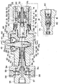
図7乃至図14は本発明に係る管継手の実施の形態の第2例を示したもので、図7は本例の管継手のソケット本体とプラグの接続前の状態の縦断面図、図8は図7のC−C線断面図、図9はソケット本体にプラグを接続可能位置まで挿入した状態を示す一部切欠平面図、図10(A)は図7の状態での本例の管継手での開閉バルブと筒状シール体との関係を示す縦断面図、図10(B)は横断面図、図11はカムの回転の過程で、ソケットとプラグは接続されるが開閉バルブは開いていない状態を示す一部切欠平面図、図12は図11の状態での本例の管継手での開閉バルブと筒状シール体との関係を示す弁孔の箇所での開閉バルブと筒状シール体との横断面図、図13はカムの回転によりソケットとプラグが接続し且つ開閉バルブが開いた状態を示す縦断面図、図14は図13の一部切欠平面図である。
【0031】
本例の管継手は、ソケット本体20と、このソケット本体20に着脱自在に接続するプラグ21とで構成されている。ソケット本体20は、筒状のソケット主筒体22を備え、その内部には流路23が形成されている。この流路23には、前記流路23を開閉する開閉バルブ24が組み込まれており、開閉バルブ24を挟んで流路23の一方を該流路23に流体が供給される1次側流路23a、他方を流路23からプラグ21側に流体を送り出す2次側流路23bとしている。
【0032】
前記開閉バルブ24にあっては、ボールバルブ、シャフトバルブが使用されるが、本例ではシャフトバルブが使用されている。本例のシャフトバルブからなる開閉バルブ24は、ソケット主筒体22を垂直に貫通する柱状のバルブ回転軸25の途中でソケット本体20の流路23に対応する部分にバルブ流路26を水平向きに貫通させた構造になっている。バルブ回転軸25の両端は小径部25a,25bとなっている。開閉バルブ24は、ソケット主筒体22に前記流路23と交差するように形成された孔27にその上部から挿入され、孔27の開放された上部には押え具28が螺着してソケット主筒体22に固定されている。バルブ回転軸25の両端の小径部25a,25bとその段部にはシールリング29が介在され、シールがなされている。また、ソケット主筒体22と押え具28との間にもシールリング30が介在され、シールがなされている。
【0033】
ソケット主筒体22の1次側には、内部を1次側流路23aとする固定筒体31がシールリング32を介して螺着されている。この固定筒体31の螺着に際して、この固定筒体31のフランジ部31aで抜け止めされて環状の取付け座33が該固定筒体31に嵌められて支持されている。フランジ部31aの外周と取付け座33との間には、シールリング34が介在され、シールがなされている。取付け座33と固定筒体31には、内部を1次側流路23aとするアダプタ35が固定筒体31との間にシールリング36を介して嵌合され、取付け座33の孔37に嵌められてアダプタ35に螺合されたネジ38で該アダプタ35が抜け止めされている。
【0034】
開閉バルブ24のバルブ流路26に対向する1次側流路23a内には、弾性を有する樹脂またはゴム等で形成された弁座を兼ねた筒状のパッキン39が、その先端開口部側を開閉バルブ24の外周面に接触させて配置されている。このパッキン39の後端側には、先端を前記パッキン39の後端外周に嵌合した筒状押圧体40が配置されている。前記パッキン39の外周とソケット主筒体22との間にはシールリング41が介在され、シールがなされている。1次側流路23a内には、固定筒体31と筒状押圧体40の間に介在したスプリング42が配置され、筒状押圧体40を介してパッキン39を押圧して開閉バルブ24の外周面に接触させている。
【0035】
開閉バルブ24の上端、即ちバルブ回転軸25には、該バルブ回転軸25をその軸心を中心に回転させるハンドル43が後述するカム44と一体となって固定されている。開閉バルブ24を構成するバルブ回転軸25には、開閉バルブ24が閉状態のとき、即ち、バルブ流路26とソケット本体20の流路23が不一致状態にあるとき、開となってプラグ21側の2次側流路23b内の残圧流体を除去する第1流路45と第2流路46が形成されている。
【0036】
前記第1流路45と第2流路46とは連通しており、前記第1流路45は前記バルブ流路26と同じ向きでバルブ回転軸25の外周面に開口しており、第2流路46はバルブ回転軸25の下端に開口し、バルブ流路26が閉のときソケット主筒体22に形成されている流体回収用通路47と連通するようになっている。
【0037】
前記バルブ流路26と第1流路45及び第2流路46と流体回収用通路47との関係を詳細に説明すると、バルブ流路26が閉で第1流路45及び第2流路46が開の状態から、開閉バルブ24を構成するバルブ回転軸25を開閉バルブ24の開方向に回転させたとき、開閉バルブ24が開となる前に、即ちバルブ流路26が1次側流路23a内で開口する前に、第1流路45の入口が前記パッキン39により閉じられ、バルブ流路26が1次側流路23a内で開口しているときは、第1流路45の入口が前記パッキン39により閉じられた状態にあるとともに、第2流路46と流体回収用通路47とが連通しない状態が得られるようになっている。そして、バルブ流路26が開で第1流路45及び第2流路46が閉の状態からバルブ回転軸25を開閉バルブ24の閉方向に回転させたとき、バルブ流路26がパッキン39により閉じられた後に、第1流路45の入口が前記パッキン39の端部から外れ、開状態となるとともに、第2流路46と流体回収用通路47との連通する状態が得られるように位置設定されている(図12参照)。
【0038】
ソケット主筒体22の2次側には、内部を2次側流路23bとするソケット分割筒体48が螺着されている。ソケット分割筒体48の外周とソケット主筒体22との間にはシールリング49が介在され、シールがなされている。
【0039】
ソケット分割筒体48の外周には、該ソケット分割筒体48を介してソケット主筒体22と一体となってソケット本体20の先端部を構成する先端筒体50が螺着されている。この先端筒体50の先端部には、ソケット本体20とプラグ21を接続する施錠機構51を備えている。この施錠機構51にあっては、本例では、周方向にボール等からなる施錠子52を嵌合した複数の施錠子嵌合孔53を有し、そして、先端筒体50の外周には、前進して施錠子52を求心方向に押え、後退してその押えを解放するスリーブ54が軸方向に移動自在に嵌合され、該スリーブ54はスプリング55により後退方向に付勢されている。
【0040】
更に、施錠機構51は、スリーブ54を後退位置で固定し、ソケット本体20に挿入したプラグ21の外周に形成された後述するところの係合溝79が施錠子52の係合可能な位置に達したとき固定を解くスリーブ固定手段56を備えている。
【0041】
このスリーブ固定手段56は、本例では、次のように構成されている。ソケット本体20の先端筒体50に備えた施錠子52の後方に位置して、周方向にボール等からなる固定子57を求遠心方向に出没自在に嵌合した複数の固定子嵌合孔58が先端筒体50に設けられ、そして、前記スリーブ54の内周には、後退位置で遠心方向に移動した固定子57に係止可能な係止溝59が形成されている。そして、前記先端筒体50の内部には、スプリング60により前進方向に付勢されたカラー61が軸方向に移動自在に嵌合されており、ソケット本体20とプラグ21の接続時にプラグ21の先端で押されて後退するようになっている。このカラー61の外周に、カラー61が前進位置にあるときにその外周で固定子57の没入を阻止し遠心方向に移動させる押圧凸部62が設けられているとともに、プラグ21の挿入により後退し、プラグ21の係合溝79が施錠子52の係合可能な位置に達したときに固定子57の没入を可能にする解放凹部63が設けられた構造となっている。先端筒体50の内周には、カラー61が前進位置にあるときに押圧凸部62が当たる小内径部50aを備えている。
【0042】
カラー61の外周面に形成された押圧凸部62と解放凹部63は、カラー61の外径を大径部と小径部にすることにより形成されており、そして、大径部と小径部の間に形成される段部64が、カラー61の前進位置で先端筒体50の小内径部50aに係止されて、先端筒体50から前進方向への抜け出しが防止されるようになっている。
【0043】
前述のように構成される施錠機構51には、前記カム44の回転により前記スリーブ54を前進移動させ且つ後退の規制を受ける移動規制部65が設けられている。この移動規制部65にあっては、本例では次のように構成されている。
【0044】
ソケット主筒体22の先端外周と先端筒体50の外周に跨がって軸方向に摺動自在に嵌合された規制筒66の先端部がスリーブ54の基端に螺合されて一体に固定され、一体に軸方向に動くようになっている。前記スリーブ54を後退方向に付勢するスプリング55は、規制筒66と先端筒体50との間に介装されており、スプリング55の基端は先端筒体50の外周に設けられたワッシャを介してストップリング67によって支持されている。
【0045】
前記規制筒66には前記カム44の外周面に当接するカム当接部68が後方に突設されている。前記カム44は、前記スリーブ54を前進方向に移動させるとともにスリーブ54の後退を阻止するスリーブ押圧兼スリーブ後退規制凸部44aとスリーブ54の後退を可能にするとともに後退したスリーブ54に係止してカム44の回転を阻止するスリーブ押圧解放兼カム回転規制凹部44bとを備えている。
【0046】
そして、前記カム44のスリーブ押圧解放兼カム回転規制凹部44bがスリーブ54の後端の規制筒66のカム当接部68と対向位置にあるとき、前記スリーブ54が後退位置にあり且つスリーブ固定手段56で後退位置に固定された状態にあり、前記開閉バルブ24が閉状態にあるとともに前記2次側流路23b内の残圧を除去する第1流路45及び第2流路46が開状態にあり、(図7、図10)、カム44を回転させることにより、スリーブ押圧兼スリーブ後退規制凸部44aにより前記後退位置にある前記規制筒66のカム当接部68が押圧されスリーブ54が前進位置に移動したとき、先ず、カム44の回転と一体に回転する開閉バルブ24の閉状態を保ちながら前記2次側流路23b内の残圧を除去する第1流路45及び第2流路46が閉状態となり(図11、図12)、更なるカム44の回転により前記第1流路45及び第2流路46の閉状態を保ちながら開閉バルブ24が開状態となるように設定されている(図13、図14)。
【0047】
前記カム44は、本例では、円盤の一部が直線状にカットされた形状を呈し、バルブ回転軸25の中心からの半径が一定な円弧状外周端を前記スリーブ押圧兼スリーブ後退規制凸部44aとし、カットされた部分を前記スリーブ押圧解放兼カム回転規制凹部44bとしている。
【0048】
また、ソケット主筒体22の2次側流路23b内には、ソケット本体20とプラグ21の接続時にプラグ21の先端で押されて後退して2次側流路23bを開き、プラグ21の離脱により前進して2次側流路23bを閉じる可動弁69が軸方向に移動自在に設けられている。2次側流路23bは、開閉バルブ24側が大径に、先端側が小径に形成されている。可動弁69は、2次側流路23bの小径の部分を構成する前記ソケット分割筒体48内に摺動自在に嵌合されている。そして、2次側流路23b内には、開閉バルブ24と可動弁69との間に2次側空間70が形成されている。
【0049】
可動弁69は、前端が開口し後端が閉鎖された筒状体からなり、後端の閉鎖部を弁頭71とし、筒内を流体通路72とし、筒壁には後端側に筒内外を連通する連通孔73を形成した構成となっている。この可動弁69の外周には、前記カラー61の内周に摺動自在に嵌合している筒体74が嵌合している。そして、この筒体74は可動弁69の先端部外周に設けたストップリング(図示せず)に係止し、前進が阻止されており、この筒体74はソケット分割筒体48との間に介装されているスプリング75により前進方向に付勢され、可動弁69も筒体74を介してスプリング75により前進方向に付勢された状態にある。弁頭71には鍔部76が形成されており、この鍔部76が2次側流路23bの大径側にて大径と小径との境に形成された段部77に係止することにより、可動弁69の前進位置が規制されている。
【0050】
そして、可動弁69が前進位置にあるとき、2次側流路23bの小径側を構成するソケット分割筒体48の内壁に装着したシールリング78により、ソケット分割筒体48の内壁と可動弁69の弁頭71の外周との間がシールされて2次側流路23bが閉じられ、可動弁69が後退位置にあるとき、筒壁に形成された連通孔73が2次側流路23bの大径側に開口して、2次側流路23bの大径側と可動弁69の流体通路72が連通する、即ち2次側流路23bが開くようになっている。
【0051】
なお、前記シールリング29,30,32,36,41,49,78は、いずれもOリングとバックアップリングとから構成されている。
【0052】
このようなソケット本体20に接続されるプラグ21は、その先端外周に施錠子52が嵌合する係合溝79が形成されている。また、内部に形成されたプラグ流体通路80内には、スプリング81の付勢により前進してプラグ流体通路80を閉じ、ソケット本体20側から供給される圧力流体の流体圧により後退してプラグ流体通路80を開く可動弁82が設けられている。
【0053】
このように構成された本例の管継手は、ソケット本体20とプラグ21が接続されていないとき、前記カム44のスリーブ押圧解放兼カム回転規制凹部44bがスリーブ54の後端にある規制筒66のカム当接部68と対向位置にあり、前記スリーブ54はスプリング55に付勢されて後退位置にあり、そして、スリーブ固定手段56を構成するカラー61がスプリング60に付勢されて前進位置にあって、前記スリーブ54を後退位置で固定した状態にある。また、前記開閉バルブ24は閉状態にあるとともに前記2次側流路23b内の残圧を除去する前記第1流路45及び第2流路46が開状態にある。
【0054】
そして、この状態でハンドル43を操作してカム44を回転させようとしても、カム44に備えられているスリーブ押圧解放兼カム回転規制凹部44bが、前記後退位置に固定されているスリーブ54の規制筒66のカム当接部68に係止してカム44の回転が阻止され開閉バルブ24を開くことはできない(図7、図8、図10)。
【0055】
ソケット本体20とプラグ21の接続に際し、前記の状態から、ソケット本体20にプラグ21を挿入すると、前記カラー61及び可動弁69がプラグ21の先端に押されて後退し、挿入した前記プラグ21の前記係合溝79が前記施錠子52の真下に達したとき、前記後退するカラー61の外周に設けられている解放凹部63が固定子57の下位に達して遠心方向への押圧を解放し、前記スリーブ54を固定していた固定子57の求心方向への移動を可能にし、これによりスリーブ54の固定が解かれ、ここに至って初めてスリーブ54の前進方向への移動が可能となる(図9)。
【0056】
この状態から、ハンドル43を操作してバルブ回転軸25を介してカム44を回転させると、スリーブ押圧兼スリーブ後退規制凸部44aにより前記後退位置にある前記規制筒66のカム当接部68が押圧されて前記スリーブ54が前進位置に移動し、求心方向への没入が可能となった前記施錠子52が求心方向に押圧されて前記係合溝79に係合し、これによりソケット本体20とプラグ21が接続される(図11)。
【0057】
そして、ソケット本体20とプラグ21が接続されてから、先ず、前記カム44の回転と一体に回転する開閉バルブ24がパッキン39でシールされて閉状態を保ちながら前記2次側流路23b内の残圧を除去する第1流路45及び第2流路46のうちの第1流路45がパッキン39でシールされ閉状態となるとともに、第2流路46と流体回収用通路47との連通が遮断される(図12)。
【0058】
更にカム44を回転させると、前記第1流路45及び第2流路46の閉状態を保ちながら開閉バルブ24のバルブ流路26が1次側流路23aと連通し、開状態となる(図13)。この状態で、前記前進位置にあるスリーブ54はスリーブ押圧兼スリーブ後退規制凸部44aにより後退が阻止された状態にあり、ソケット本体20とプラグ21の分離操作はできない(図14)。
【0059】
ソケット本体20とプラグ21の分離時に、ハンドル43を操作してバルブ回転軸25を介してカム44を回転させると、スリーブ押圧兼スリーブ後退規制凸部44aが前記スリーブ54を押圧して前進位置に移動させている状態を保持しながら、回転の途中で、先ず開閉バルブ24がパッキン39でシールされ閉状態となり、次いで第1流路45及び第2流路46のうちの第1流路45がパッキン39の端部から外れて開状態となるとともに、第2流路46と流体回収用通路47が連通し、前記2次側流路23b内の残圧が除去された後、更なるカム44の回転によりスリーブ押圧解放兼カム回転規制凹部44bがスリーブ54の後端と対向位置に移動し、これにより前進方向への押圧を解かれたスリーブ54はスプリング55に付勢されて後退し、前記ソケット本体20とプラグ21の施錠が解かれ、ソケット本体20とプラグ21を分離することができる。
【0060】
ソケット本体20とプラグ21を分離すると、前記プラグ21の先端により押圧され後退していたカラー56がスプリング57に付勢されて前進し、スリーブ固定手段56によって後退位置にあるスリーブ54が同位置に固定される。
【0061】
前記ソケット本体20とプラグ21の接続分離操作に際し、ソケット本体20とプラグ21の接続時には、ソケット本体20の2次側流路23b内の残圧を除去する第1流路45及び第2流路46が開状態にあるので、ソケット本体20とプラグ21の接続を容易に行うことができ、また、ソケット本体20とプラグ21の分離時には、分離の前に第1流路45及び第2流路46が開状態になりソケット本体20の2次側流路23b内の残圧を除去するので、ソケット本体20とプラグ21の分離を安全に行うこととができる。
【0062】
【発明の効果】
以上のように本発明に係る管継手によれば、部品点数を抑えながら、確実に残圧除去を行うことができる。また本発明は、残圧はソケット本体から直接外部に放出する機構とするため、開閉弁を操作するだけで、残圧を除去することができ、特に高圧な流体を供給する経路に使用した場合であっても、ソケットとプラグの接続分離を安全に且つ容易に行うことができ、また、プラグ離脱時に手を汚すことがなく、また、不快な音等の発生もない。更には、構造が簡単なのでコンパクト化が可能となり、コストダウンをも図ることができる。
【図面の簡単な説明】
【図1】
本発明に係る管継手の実施の形態の第1例を示した平面図である。
【図2】
プラグが接続された状態の図1のA−A線断面図(開閉バルブが開状態の断面
図)である。
【図3】
開閉バルブにパッキンを当接させた状態の左側面図である。
【図4】
図2のB−B線断面図である。
【図5】
図2に対応する断面図でプラグが接続された状態の開閉バルブが閉状態の断面
図である。
【図6】
図5において開閉バルブとパッキンとを非断面とした断面図である。
【図7】
本発明に係る管継手の実施の形態の第2例を示したソケットとプラグの接続前
の状態の縦断面図である。
【図8】
図7のC−C線断面図である。
【図9】
ソケットにプラグを接続可能位置まで挿入した状態を示す一部切欠平面図であ
る。
【図10】
(A)は図7の状態での本例の管継手での開閉バルブと筒状シール体との関係
を示す縦断面図、(B)は横断面図である。
【図11】
カムの回転の過程で、ソケットとプラグは接続されるが開閉バルブは開いてい
ない状態を示す一部切欠平面図である。
【図12】
図11の状態での本例の管継手での開閉バルブと筒状シール体との関係を示す
弁孔の箇所での開閉バルブと筒状シール体との横断面図である。
【図13】
カムの回転によりソケットとプラグが接続し且つ開閉バルブが開いた状態を示
す縦断面図である。
【図14】
図13の一部切欠平面図である。
【符号の説明】
1 ソケット本体
2 流路
3 開閉バルブ
3a つまみ
3b 流路
3c 第1流路
3d 第2流路
3e シール面
3f カム部
3g ストップリング
4 孔
5 パッキン
5a 鍔
6 パッキン収納部
7 貫通孔
8 Oリング
9 スリーブ
10 係止部材
11 スプリング
12 シール部材
13 ストップリング
20 ソケット本体
21 プラグ
22 ソケット主筒体
23 流路
23a 1次側流路
23b 2次側流路
24 開閉バルブ
25 バルブ回転軸
25a,25b 小径部
26 バルブ流路
27 孔
28 押え具
29,30 シールリング
31 固定筒体
31a フランジ部
32 シールリング
33 取付け座
34 シールリング
35 アダプタ
36 シールリング
37 孔
38 ネジ
39 パッキン
40 筒状押圧体
41 シールリング
42 スプリング
43 ハンドル
44 カム
44a スリーブ押圧兼スリーブ後退規制凸部
44b スリーブ押圧解放兼カム回転規制凹部
45 第1流路
46 第2流路
47 流体回収用通路
48 ソケット分割筒体
49 シールリング
50 先端筒体
50a 小内径部
51 施錠機構
52 施錠子
53 施錠子嵌合孔
54 スリーブ
55 スプリング
56 スリーブ固定手段
57 固定子
58 固定子嵌合孔
59 係止溝
60 スプリング
61 カラー
62 押圧凸部
63 解放凹部
64 段部
65 移動規制部
66 規制筒
67 ストップリング
68 カム当接部
69 可動弁
70 2次側空間
71 弁頭
72 流体通路
73 連通孔
74 筒体
75 スプリング
76 鍔部
77 段部
78 シールリング
79 係合溝
80 プラグ流体通路
81 スプリング
82 可動弁
[Document name] statement
Patent application title: Pipe fitting
[Claim of claim]
[Claim 1]
A socket in a pipe joint having a socket and a plug inserted into and coupled to the socket
A fluid passage having a first end for connecting a conduit and a second end for connecting a plug;
Movable between an open position provided in the fluid passage and permitting fluid flow between the first end side and the second end side of the fluid passage, and a closed position blocking the fluid flow With the on-off valve,
Have
The open / close valve communicates the second end side of the fluid passage with the outside of the pipe joint when in the closed position, and is a purge flow path closed when the open / close valve is in the open position Is provided
Socket that is characterized by
[Claim 2]
A valve setting hole provided to intersect the fluid passage;
A packing having a through hole aligned and communicated with the fluid passage;
Have
The open / close valve is cylindrical and coaxially set in the valve setting hole, and can be pivoted between the open position and the closed position about the central axis, the open position And has an outer circumferential surface that slides in sealing engagement with the packing when pivoting between
The purge passage has an inner opening at one end opening to the outer peripheral surface of the on-off valve, and an outer opening communicating with the outside of the pipe joint at the other end, the inner opening being the Sealed engagement with the packing is closed when the on-off valve is in the open position and disengaged from sealing engagement with the packing when the on-off valve is in the closed position, the second end of the fluid passage It is made to communicate with the part side
The socket according to claim 1, characterized in that:
[Claim 3]
The valve setting hole has a circular cross section, and is set to be orthogonal to the fluid passage,
The fluid passage intersects the peripheral wall surface of the valve setting hole to form a pair of openings,
The packing has a through hole aligned with one of the pair of openings and has a sealing engagement surface arced around the axis of the valve setting hole;
The outer peripheral surface of the on-off valve has a diameter that slides in sealing engagement with the sealing engagement surface of the packing;
A gap is formed between the outer peripheral surface and the peripheral wall surface of the valve setting hole, and the other of the pair of openings is in communication with the gap,
The on-off valve has a valve hole extending in a diametrical direction at right angles to the axis of the on-off valve, penetrating through the on-off valve, and opening on the outer peripheral surface of the on-off valve
The valve hole is communicated with the through hole of the packing when the on-off valve is in the open position, and the communication with the through hole is blocked when the on-off valve is in the closed position. Yes,
The inner opening of the purge flow passage is closed by the sealing engagement surface of the packing when the on-off valve is in the open position, and the sealing engagement surface of the packing when the on-off valve is in the closed position Open to a position where it is disengaged and in communication with the gap
The socket according to claim 2, characterized in that:
[Claim 4]
A hole formed radially through the peripheral wall of the socket defining the second end fluid passage;
Set in the bore and movable in the radial direction of the socket,
A locking position for engaging a plug inserted in the socket to lock the plug relative to the socket;
The unlocking position where the engagement with the plug is released and the plug is unlocked from the socket,
A lock that can be displaced between the
With a sleeve that is set slidably on the outer circumference of the socket peripheral wall,
A first position where the locking element is pressed radially inward to set the locking element as the fixed position;
The pressing of the locking element is released on the side of the on-off valve rather than the first position, and it is possible to slide between the second position which allows the locking element to be in the fixed release position. With the sleeve,
A spring biasing the sleeve towards the first position;
A cam attached to the on-off valve, wherein the plug is inserted into the socket and the on-off valve is moved from the closed position to the open position when the sleeve is in the first position. And a cam engaged to prevent the sleeve from being brought into the second position
Have
The socket according to any one of claims 1 to 3, characterized in that:
[Claim 5]
A first hole formed radially through the peripheral wall of the socket defining the fluid passage on the second end side;
A fixed position set in the first hole and movable in the radial direction of the socket for engaging the plug inserted in the socket to lock the plug relative to the socket;
The unlocking position where the engagement with the plug is released and the plug is unlocked from the socket,
A lock that can be displaced between the
A first position is set slidably on the outer periphery of the peripheral wall of the socket and the locking element is pressed inward in the radial direction to set the locking element as the fixed position, and the opening and closing relative to the first position. A sleeve which is slidable between a second position which releases the pressing of the locking element and allows the locking element to be in the fixed release position on the side of the valve;
A first spring biasing the sleeve towards the second position;
A second hole formed radially through the peripheral wall of the socket;
A stator set radially movable in said second bore,
A fixed position engaged with the sleeve in the second position to prevent the sleeve from being moved to the first position;
An unlocked position which is moved radially inward from the locked position to allow the sleeve to be moved towards the first position.
And a stator made movable between
A stator holding member set in the fluid passage on the second end side, the stator holding member comprising:
A first position for holding the stator in the fixed position;
A second position closer to the on-off valve than the first position, which allows the stator to be in the unlocked position;
Be movable between
A stator holding member which is moved by a plug inserted into the socket to be brought into the second position when the plug is in a position to be connected to the socket;
A second spring biasing the stator holding member to the first position;
The socket according to any one of claims 1 to 3, characterized in that
[6]
It has a cam attached to the on-off valve and engaged with the sleeve, the cam
When the plug is in the position where it is inserted into the socket and connected with the socket,
When the on-off valve is moved from the closed position to the open position, the sleeve is moved from the second position to the first position against the first spring;
Causing the first spring to move the sleeve from the first position to the second position when the on-off valve is moved from the open position to the closed position;
When the plug is not inserted into the socket, engagement with the sleeve prevents the on / off valve from moving from the closed position to the open position.
The socket according to claim 5, characterized in that:
Detailed Description of the Invention
[0001]
Field of the Invention
The present invention relates to a pipe joint having a flow control function and a residual pressure removing function, and in particular to a pipe joint suitable for attaching and detaching a path for supplying a high pressure fluid.
[0002]
[Prior Art]
As a pipe joint equipped with a flow rate adjustment and residual pressure removal function, which is particularly suitable for attaching and detaching a path for supplying a high pressure fluid, an on-off valve that opens and closes manually is incorporated. There are many pipe fittings whose operation procedures are restricted such as opening operation after completing the connection between the socket body and the plug, and separation of the socket body and the plug after completing the closing operation of the on-off valve.
[0003]
As a conventional pipe joint of this type, one having a structure in which three on-off valves constituting an inlet valve means, a vent valve means and an outlet valve means are arranged in series inside is proposed (for example, see Patent Document 1) .
[0004]
[Patent Document 1]
Patent No. 2694302
[0005]
[Problems to be solved by the invention]
However, in such a pipe joint, since the three opening / closing valves constituting the inlet valve means, the vent valve means and the outlet valve means are arranged in series in the inside, the overall length becomes long, and the pressure loss is reduced. There is a problem that it becomes large and as a result, the filling efficiency becomes worse. In addition, the opening / closing operation of the opening / closing valve is restricted after the connection between the socket body and the plug is completed, and the closing operation of the opening / closing valve is completed, and then the socket body and the plug are separated. Is complex, and as described above, it has a structure in which the three on-off valves constituting the inlet valve means, the vent valve means and the outlet valve means are arranged in series as described above, so the number of parts is large and the structure is Since it becomes complicated, there is a problem that it becomes a factor which becomes large in a pipe joint and also becomes a factor which raises cost.
[0006]
The present invention is made in view of the above-mentioned problems of the conventional pipe joint.
[0007]
[Means for Solving the Problems]
That is, the present invention relates to a socket in a pipe joint having a socket and a plug inserted into and coupled to the socket.
A fluid passage having a first end for connecting the conduit and a second end for connecting the plug (corresponding to the ones indicated by reference numerals 2 and 23 in the description of the embodiments described below);
Movable between an open position provided in the fluid passage and permitting fluid flow between the first end side and the second end side of the fluid passage, and a closed position blocking the fluid flow With the on-off valve (3, 24)
Have
The open / close valve communicates the second end side of the fluid passage with the outside of the pipe joint when in the closed position, and is a purge flow path closed when the open / close valve is in the open position (A flow path for removing residual pressure which is constituted by flow paths 3c, 3d, 45, 46 and the like in the embodiment described below) is provided
To provide a socket with the basic features.
[0008]
Specifically, this socket is
A valve setting hole (4, 27) provided to intersect the fluid passage;
A packing (5, 39) having a through hole aligned and communicated with the fluid passage;
Have
The open / close valve is cylindrical and coaxially set in the valve setting hole, and can be pivoted between the open position and the closed position about the central axis, the open position And has an outer peripheral surface (corresponding to "seal surface 3e") that slides in sealing engagement with the packing when rotating between the second position and the closed position,
The purge passage has an inner opening at one end opening to the outer peripheral surface of the on-off valve, and an outer opening communicating with the outside of the pipe joint at the other end, the inner opening being the Sealed engagement with the packing is closed when the on-off valve is in the open position and disengaged from sealing engagement with the packing when the on-off valve is in the closed position, the second end of the fluid passage It is made to communicate with the part side.
[0009]
More specifically, the valve setting hole has a circular cross section, and is set to be orthogonal to the fluid passage. The fluid passage intersects the peripheral wall surface of the valve setting hole to form a pair of openings, and the packing is arranged such that the through hole is in proper communication with one of the pair of openings. A sealing engagement surface having a circular arc shape about the axis of the setting hole, and the outer peripheral surface of the on-off valve has a diameter that slides in sealing engagement with the sealing engagement surface of the packing; A gap is formed between the outer peripheral surface and the peripheral wall surface of the valve setting hole, and the other of the pair of openings is in communication with the gap, and the on-off valve is on the axis of the on-off valve. It has a valve hole (3b, 26) which extends in a diametrical direction to the right at right angles and penetrates the on-off valve and is opened on the outer peripheral surface of the on-off valve. When it is communicated with the through hole of the When the valve is in the closed position, the communication with the through hole is shut off, and the inner opening of the purge passage is closed when the on-off valve is in the open position. It is closed by the joint surface, and when the on-off valve is in the closed position, the packing is disengaged from the sealing engagement surface of the packing and is opened to the position communicated with the gap.
[0010]
One specific example is
A hole formed radially through the peripheral wall of the socket defining the second end fluid passage;
Set in the bore and movable in the radial direction of the socket,
A locking position for engaging a plug inserted in the socket to lock the plug relative to the socket;
The unlocking position where the engagement with the plug is released and the plug is unlocked from the socket,
A lock (10) that is displaceable between the
With a sleeve (9) slidably set on the outer circumference of the socket peripheral wall,
A first position where the locking element is pressed radially inward to set the locking element as the fixed position;
The pressing of the locking element is released on the side of the on-off valve rather than the first position, and it is possible to slide between the second position which allows the locking element to be in the fixed release position. With the sleeve,
A spring (11) biasing the sleeve towards the first position;
A cam (3f) attached to the on-off valve, wherein when the plug is inserted into the socket and the sleeve is in the first position, the on-off valve is moved from the closed position to the open position; A cam engaged with the sleeve to prevent the sleeve from being brought into the second position
Have.
[0011]
Another specific example is
A first hole formed radially through the peripheral wall of the socket defining the fluid passage on the second end side;
A fixed position set in the first hole and movable in the radial direction of the socket for engaging the plug inserted in the socket to lock the plug relative to the socket;
The unlocking position where the engagement with the plug is released and the plug is unlocked from the socket,
A lock (52) that is displaceable between the
A first position is set slidably on the outer periphery of the peripheral wall of the socket and the locking element is pressed inward in the radial direction to set the locking element as the fixed position, and the opening and closing relative to the first position. A sleeve (54) slidable between the valve and the second position which releases the pressing of the locking element and allows the locking element to be in the fixed release position;
A first spring (55) biasing the sleeve towards the second position;
A second hole formed radially through the peripheral wall of the socket;
A stator (57) set radially movable in said second bore,
A fixed position engaged with the sleeve in the second position to prevent the sleeve from being moved to the first position;
An unlocked position which is moved radially inward from the locked position to allow the sleeve to be moved towards the first position.
And a stator made movable between
A stator holding member (corresponding to “collar 61”) set in the fluid passage on the second end side,
A first position for holding the stator in the fixed position;
A second position closer to the on-off valve than the first position, which allows the stator to be in the unlocked position;
Be movable between
A stator holding member which is moved by a plug inserted into the socket to be brought into the second position when the plug is in a position to be connected to the socket;
A second spring (55) biasing the stator holding member to the first position;
Have.
[0012]
Furthermore, in this embodiment, it has a cam (44) attached to the on-off valve and engaged with the sleeve, the cam
When the plug is in the position where it is inserted into the socket and connected with the socket,
When the on-off valve is moved from the closed position to the open position, the sleeve is moved from the second position to the first position against the first spring;
Causing the first spring to move the sleeve from the first position to the second position when the on-off valve is moved from the open position to the closed position;
When the plug is not inserted into the socket, engagement with the sleeve prevents the on / off valve from moving from the closed position to the open position.
[0013]
BEST MODE FOR CARRYING OUT THE INVENTION
Hereinafter, an embodiment of a pipe joint having a flow rate adjustment function and a residual pressure removing function according to the present invention will be described with reference to the drawings.
1 to 6 show a first example of an embodiment of a pipe joint according to the present invention, and FIG. 1 is a plan view of the pipe joint of this example, and FIG. 2 is an A view of FIG. 3A is a left side view of a state in which the packing is in contact with the on-off valve, FIG. 4 is a cross-sectional view on B-B in FIG. 2, FIG. FIG. 6 is a cross-sectional view in which the on-off valve and the packing are in a non-cross-section in FIG.
[0020]
In the drawings, reference numeral 1 denotes a socket main body, and the socket main body 1 is formed with a flow passage 2 at its central portion, and the socket main body 1 is configured to be able to connect a plug as shown in FIG. As shown in FIG. 1, the socket main body 1 has a substantially rectangular outer shape as shown in FIG. 1, and the left and right sides of the open / close valve 3 in the drawing are cylindrical.
[0021]
A circular hole 4 for attaching the on-off valve 3 is formed in the socket body 1 so as to intersect the flow path 2, and the on-off valve 3 can be fitted in the hole 4. On one side of the hole 4 intersecting the flow path 2 (left side in this example in the example), there is a packing storage portion 6 communicating with the flow path 2 and storing a packing 5 having a sealing function with the on-off valve 3 It is formed. The packing 5 fitted in the packing storage portion 6 has a through hole 7 having substantially the same diameter as the flow path 2 on the side of the socket main body 1 at the center, and further includes a weir 5a abutting on the outer peripheral surface of the on-off valve 3 described later. The crucible 5a is formed in a semicircular shape that abuts on the outer peripheral surface of the on-off valve 3 as shown in FIG. 4 and has a square shape as shown in FIG.
[0022]
Further, as is clear from FIG. 2, the on-off valve 3 is provided with a knob 3 a and a cam portion 3 f at the upper part, and the lower part thereof has a cylindrical shape fitted in the circular hole 4 formed in the socket body 1. Further, a flow path 3b is formed in the central portion thereof. Further, a first flow path 3c directed downward for removing residual pressure is formed in the lower part of the on-off valve 3, and a second flow for residual pressure removal is in communication with the first flow path 3c at right angles. The path 3d is formed. The second flow path 3 d is formed substantially in parallel with the flow path 3 b formed in the on-off valve 3, and the open end thereof corresponds to the packing 5 as shown in FIG. 2 and FIG. It can be closed by this packing 5 when it is in the open state, and the open end is detached from the weir 5a of the packing 5 when the on-off valve 3 is closed, and connected with the flow path 2 of the socket main body 1 formed on the plug connection side Can be configured
(See Figure 4).
[0023]
The residual pressure can be removed gradually or rapidly only by operating the on-off valve 3 by changing the position and the shape of the open end of the second flow path 3d. A seal surface 3e having a sealing function is formed in contact with the packing 5 on the outer periphery of the on-off valve 3. When the packing 5 is accommodated in the packing storage portion 6, the on-off valve 3 is fitted in the hole 4. The packing 5 and the weir 5 a of the packing 5 abut on the sealing surface 3 e on the outer periphery of the on-off valve 3 to be in a sealed state. Further, O-rings 8 and 8 are disposed on the upper and lower sides of the outer peripheral surface of the on-off valve 3 to seal between the socket body 1 and the same. Further, a stop ring 3g is mounted at the lower end of the on-off valve 3 to prevent the on-off valve 3 from coming out of the socket body 1.
[0024]
The cam portion 3f has the same function as the cam means provided in the above-described conventional pipe joint, and restricts the backward movement of the sleeve 9 for separating the plug P described later when the on-off valve 3 is opened. When the on-off valve 3 is closed, the sleeve 9 is allowed to move backward.
[0025]
A plug contacting / separating mechanism consisting of a sleeve 9 and a locking member 10 known in the prior art is disposed on one side of the socket main body 1, and by operating the sleeve 9, the plug P can be contacted and separated. Since it does not exist, the detailed description of this contact / separation mechanism is omitted. In the figure, P is a plug, 9 is a sleeve, 10 is a locking member, 11 is a spring, 12 is a seal member, and 13 is a stop ring. It goes without saying that an external thread, an internal thread, a bamboo nipple or the like to which a pipe, a hose or the like can be connected is formed on the other side of the socket body 1.
[0026]
The operation of the pipe joint of this example having the above configuration will be described.
As in the state shown in FIG. 2, the plug P is inserted into the socket main body 1 in a state where the sleeve 9 is manually retracted to the left against the elastic force of the spring 11 and the pressing of the locking member 10 is released. Then, after releasing the hand from the sleeve 9 and advancing the sleeve 9 by the spring 11 to press the locking member 10 to connect the plug P, the knob 3a becomes parallel to the flow passage 2 in the socket main body 1 When operated to the position, the left and right flow channels 2 formed in the socket main body 1 communicate with each other by the flow channels 3 b formed in the on-off valve 3. At this time, the packing 5 is at a position (see FIG. 4) that closes the open end of the second flow path 3d formed in the on-off valve 3, whereby the pressure flowing to the plug side is removed through the second flow path 3d. There is no longer. By opening the on-off valve 3 in this manner, the fluid can smoothly flow to the plug side. When the on-off valve 3 is open, the cam portion 3f restricts the retraction of the sleeve 9 to prevent the plug P from being detached from the socket body 1. The flow rate can be adjusted by the rotation angle of the knob 3a.
[0027]
When the knob 3a is operated at a position perpendicular to the flow passage 2 of the socket main body 1 (see FIG. 5), the flow passage 3b formed in the on-off valve 3 is formed in the socket main body 1 Is in a non-communicating state, and the flow path 2 can be closed. In this closed state, the open end of the second flow path 3d formed in the on-off valve 3 is disengaged from the weir 5a of the packing 5 (dotted line position in FIG. 4). Communicates with the outside through the second flow path 3d and the first flow path 3c, and the residual pressure is released to the outside. Further, when the open / close valve 3 is in the closed state, the restriction on the retraction of the sleeve 9 is released by the cam portion 3f, and the plug P can be separated from the socket body 1 by retracting the sleeve 9. If a female screw is formed in the hole of the first flow path 3c of the on-off valve 3 but a female screw is formed, a nipple is screwed, a hose or the like is connected to the nipple and the residual pressure is released at a position far from the socket main body 1 It can be configured to
[0028]
As described above, in the pipe joint of the present embodiment, the flow path 2 in the socket main body 1 can be communicated or blocked only by operating the open / close valve 3 provided on the socket main body 1 side. Since residual pressure is removed only by closing 3, there is no need to retract the holding member after closing the open / close mechanism as in the prior art, and at that time residual pressure from between the holding member and the opening means Will not contaminate the operator's hand which ejects and removes the plug P. Furthermore, since the drain does not enter the outer peripheral surface of the socket body 1 and the inner peripheral surface of the sleeve, the movement of the sleeve does not become worse by the drain.
[0029]
In addition, although the on-off valve is provided on the socket side in the pipe joint of this example, it is also possible to provide the on-off valve on the plug side. Also, the mechanism for connecting the socket and the plug by operating the sleeve can adopt the same function or other configuration. Further, the shape of the flow path for removing the residual pressure is not limited to the above example. Further, the flow path formed in the on-off valve does not necessarily have the same diameter as the flow path formed on the socket main body side, and may have a small diameter or a large diameter. Further, the outer shape of the socket main body can take various forms such as a polygon (both cylindrical on the left and right, a polygon on both the left and right, a combination of a polygon and a circle, etc.) other than this example.
[0030]
7 to 14 show a second example of the embodiment of the pipe joint according to the present invention, and FIG. 7 is a longitudinal sectional view of a state before connection of the socket main body and the plug of the pipe joint of this example, 8 is a cross-sectional view taken along the line C-C in FIG. 7, FIG. 9 is a partially cutaway plan view showing a state in which the plug is inserted into the socket body to a connectable position, FIG. Longitudinal sectional view showing the relationship between the on-off valve and the tubular seal body in the pipe joint, FIG. 10 (B) is a transverse sectional view, FIG. 11 is a process of rotating the cam. 12 is a partially cutaway plan view showing the unopened state, and FIG. 12 is an open / close valve at the valve hole showing the relationship between the on-off valve and the cylindrical seal in the pipe joint of this example in the state of FIG. Fig. 13 shows the socket and the plug connected by the rotation of the cam and the open / close valve opened. Longitudinal sectional view showing a state, FIG. 14 is a partially cutaway plan view of FIG. 13.
[0031]
The pipe joint of this embodiment is constituted by a socket body 20 and a plug 21 detachably connected to the socket body 20. The socket main body 20 is provided with a cylindrical socket main cylindrical body 22, and a flow path 23 is formed therein. An open / close valve 24 for opening and closing the flow passage 23 is incorporated in the flow passage 23, and a primary side flow passage in which the fluid is supplied to the flow passage 23 at one side of the flow passage 23 with the open / close valve 24 interposed therebetween. The other side 23 a is a secondary side flow path 23 b for sending out the fluid from the flow path 23 to the plug 21 side.
[0032]
In the opening and closing valve 24, a ball valve and a shaft valve are used, but in this example, a shaft valve is used. The on-off valve 24 consisting of the shaft valve of this example has the valve flow path 26 horizontally oriented to a portion corresponding to the flow path 23 of the socket main body 20 in the middle of the columnar valve rotary shaft 25 vertically penetrating the socket main cylinder 22 It has a structure that is penetrated. Both ends of the valve rotary shaft 25 are the small diameter portions 25a and 25b. The opening / closing valve 24 is inserted into the hole 27 formed in the socket main cylinder 22 so as to intersect with the flow path 23 from the upper part, and the pressing tool 28 is screwed into the open upper part of the hole 27 It is fixed to the main cylinder 22. A seal ring 29 is interposed between the small diameter portions 25a and 25b at both ends of the valve rotary shaft 25 and the stepped portion thereof, and sealing is performed. Further, a seal ring 30 is interposed between the socket main cylinder 22 and the presser 28, and sealing is performed.
[0033]
On the primary side of the socket main cylinder 22, a fixed cylinder 31 whose inside is a primary side flow passage 23 a is screwed via a seal ring 32. At the time of screwing of the fixed cylindrical body 31, the annular mounting seat 33 is engaged with and supported by the fixed cylindrical body 31 by being held off by the flange portion 31 a of the fixed cylindrical body 31. A seal ring 34 is interposed between the outer periphery of the flange portion 31 a and the mounting seat 33 to seal. An adapter 35 whose inside is the primary side flow passage 23 a is fitted to the mounting seat 33 and the fixed cylindrical body 31 through the seal ring 36 between the mounting seat 33 and the fixed cylindrical body 31 with the fixed cylindrical body 31. The adapter 35 is held off by a screw 38 screwed to the adapter 35.
[0034]
In the primary side flow passage 23a opposed to the valve flow passage 26 of the opening / closing valve 24, a cylindrical packing 39 also serving as a valve seat formed of an elastic resin, rubber, etc. It is disposed in contact with the outer peripheral surface of the on-off valve 24. On the rear end side of the packing 39, a cylindrical pressing body 40, the tip of which is fitted to the outer periphery of the rear end of the packing 39, is disposed. A seal ring 41 is interposed between the outer periphery of the packing 39 and the socket main cylinder 22 to seal. A spring 42 interposed between the fixed cylindrical body 31 and the cylindrical pressing body 40 is disposed in the primary side flow passage 23a, and the packing 39 is pressed via the cylindrical pressing body 40 to thereby form the outer periphery of the open / close valve 24. It is in contact with the surface.
[0035]
At the upper end of the on-off valve 24, that is, the valve rotary shaft 25, a handle 43 for rotating the valve rotary shaft 25 about its axis is integrally fixed with a cam 44 described later. The valve rotary shaft 25 constituting the on-off valve 24 is opened when the on-off valve 24 is in the closed state, that is, when the valve flow path 26 and the flow path 23 of the socket main body 20 do not match. The 1st flow path 45 and the 2nd flow path 46 which remove the residual pressure fluid in secondary side flow path 23b are formed.
[0036]
The first flow path 45 and the second flow path 46 communicate with each other, and the first flow path 45 opens in the same direction as the valve flow path 26 to the outer peripheral surface of the valve rotation shaft 25. The flow passage 46 opens at the lower end of the valve rotation shaft 25 and is in communication with the fluid recovery passage 47 formed in the socket main cylinder 22 when the valve flow passage 26 is closed.
[0037]
The relationship between the valve flow passage 26 and the first flow passage 45 and the second flow passage 46 and the fluid recovery passage 47 will be described in detail. The valve flow passage 26 is closed and the first flow passage 45 and the second flow passage 46 are closed. When the valve rotary shaft 25 constituting the on-off valve 24 is rotated in the opening direction of the on-off valve 24 from the open state, that is, before the on-off valve 24 is opened, ie When the inlet of the first flow path 45 is closed by the packing 39 and the valve flow path 26 is opened in the primary flow path 23a before opening in the space 23a, the inlet of the first flow path 45 Is closed by the packing 39 and a state in which the second flow passage 46 and the fluid recovery passage 47 do not communicate with each other is obtained. Then, when the valve rotary shaft 25 is rotated in the closing direction of the opening / closing valve 24 from the state where the valve channel 26 is open and the first channel 45 and the second channel 46 are closed, the valve channel 26 is After being closed, the inlet of the first flow path 45 is detached from the end of the packing 39 and is in an open state, and a position where communication between the second flow path 46 and the fluid recovery passage 47 is obtained It is set (see FIG. 12).
[0038]
On the secondary side of the socket main cylinder 22, a socket divided cylinder 48 whose inside is a secondary flow passage 23 b is screwed. A seal ring 49 is interposed between the outer periphery of the socket divided cylindrical body 48 and the socket main cylindrical body 22, and sealing is performed.
[0039]
A distal end cylindrical body 50, which is integrated with the socket main cylindrical body 22 via the socket divided cylindrical body 48 and constitutes a distal end portion of the socket main body 20, is screwed to the outer periphery of the socket divided cylindrical body 48. A locking mechanism 51 for connecting the socket body 20 and the plug 21 is provided at the tip of the tip barrel 50. In this locking mechanism 51, in this example, the locking mechanism 51 has a plurality of locking element fitting holes 53 in which locking elements 52 made of balls or the like are fitted. A sleeve 54, which advances forward to press the locking element 52 in the centripetal direction and retracts to release the press, is axially movably fitted, and the sleeve 54 is biased by the spring 55 in the backward direction.
[0040]
Furthermore, the locking mechanism 51 fixes the sleeve 54 in the retracted position, and an engagement groove 79, which will be described later, formed on the outer periphery of the plug 21 inserted into the socket body 20 reaches a position where the locking element 52 can engage. A sleeve fixing means 56 is provided to release the fixing when it is done.
[0041]
The sleeve fixing means 56 is configured as follows in this example. A plurality of stator fitting holes 58 in which stators 57 formed of balls or the like in the circumferential direction are rotatably fitted in a centrifugal direction while being positioned behind lockers 52 provided on the end cylindrical body 50 of the socket main body 20. Is provided on the end cylinder 50, and a locking groove 59 is formed on the inner periphery of the sleeve 54 so as to be able to lock the stator 57 moved in the centrifugal direction at the retracted position. A collar 61 urged in the forward direction by a spring 60 is axially movably fitted inside the tip cylindrical body 50, and the tip of the plug 21 is connected when the socket body 20 and the plug 21 are connected. It is pushed in and is set to retreat. On the outer periphery of the collar 61, there is provided a pressing convex portion 62 which prevents immersion of the stator 57 and moves in the centrifugal direction on the outer periphery when the collar 61 is in the forward position, and is retracted by insertion of the plug 21. The release recess 63 is provided to allow the stator 57 to be retracted when the engagement groove 79 of the plug 21 reaches the position where the lock 52 can be engaged. The inner circumference of the tip end cylindrical body 50 is provided with a small inner diameter portion 50a to which the pressing convex portion 62 abuts when the collar 61 is in the forward position.
[0042]
The pressing convex portion 62 and the releasing concave portion 63 formed on the outer peripheral surface of the collar 61 are formed by making the outer diameter of the collar 61 into a large diameter portion and a small diameter portion, and between the large diameter portion and the small diameter portion The stepped portion 64 formed on the front end of the front end cylindrical body 50 is engaged with the small inner diameter portion 50 a of the front end cylindrical body 50 at the forward movement position of the collar 61 to prevent the front end cylindrical body 50 from coming off in the forward direction.
[0043]
The locking mechanism 51 configured as described above is provided with a movement restricting portion 65 which moves the sleeve 54 forwardly by the rotation of the cam 44 and receives a restriction of backward movement. The movement restricting unit 65 is configured as follows in this example.
[0044]
The distal end portion of the restricting cylinder 66 slidably fitted in the axial direction straddling the tip outer periphery of the socket main barrel 22 and the outer periphery of the tip barrel 50 is screwed with the proximal end of the sleeve 54 to be integrated. It is fixed and moves in one axial direction. A spring 55 for urging the sleeve 54 in the backward direction is interposed between the restricting cylinder 66 and the distal end cylinder 50, and the base end of the spring 55 is a washer provided on the outer periphery of the distal end cylinder 50. It is supported by the stop ring 67.
[0045]
A cam contact portion 68 that abuts on the outer peripheral surface of the cam 44 is provided on the control cylinder 66 so as to protrude rearward. The cam 44 moves the sleeve 54 in the forward direction and prevents the sleeve 54 from retreating, allowing the sleeve pressing and sleeve retraction restricting convex portion 44a and the sleeve 54 to be retracted and locking the sleeve 54 to be retracted. A sleeve pressure release and cam rotation restricting recess 44b for preventing the rotation of the cam 44 is provided.
[0046]
The sleeve 54 is in the retracted position and the sleeve fixing means when the sleeve pressure releasing and cam rotation restricting recess 44b of the cam 44 is opposite to the cam contact portion 68 of the restricting cylinder 66 at the rear end of the sleeve 54. The first flow path 45 and the second flow path 46, which are fixed at the retracted position at 56 and the open / close valve 24 is in the closed state and removes the residual pressure in the secondary side flow path 23b, are opened. And (FIG. 7, FIG. 10), by rotating the cam 44, the cam contact portion 68 of the restricting cylinder 66 in the retracted position is pressed by the sleeve pressing and sleeve retraction restricting convex portion 44a, and the sleeve 54 is When moving to the forward position, first, the first flow path 45 and the second flow which remove the residual pressure in the secondary side flow path 23b while maintaining the closed state of the on-off valve 24 which rotates integrally with the rotation of the cam 44 46 is closed (FIGS. 11 and 12), and the opening / closing valve 24 is set to be open while keeping the first channel 45 and the second channel 46 closed by further rotation of the cam 44. (Figures 13 and 14).
[0047]
In the present embodiment, the cam 44 has a shape in which a part of a disk is cut in a straight line, and an arc-like outer peripheral end having a constant radius from the center of the valve rotary shaft 25 44a, and the cut portion is used as the sleeve pressure release and cam rotation restriction recess 44b.
[0048]
Further, when the socket main body 20 and the plug 21 are connected, they are pushed by the tip of the plug 21 and retracted to open the secondary side flow passage 23 b in the secondary side flow passage 23 b of the socket main cylinder 22. A movable valve 69 is provided axially movably in the axial direction so as to move forward by separation and close the secondary flow passage 23b. The secondary flow passage 23b is formed such that the opening / closing valve 24 side has a large diameter and the tip end side has a small diameter. The movable valve 69 is slidably fitted in the socket divided cylinder body 48 which constitutes the small diameter portion of the secondary flow passage 23b. Then, a secondary space 70 is formed between the on-off valve 24 and the movable valve 69 in the secondary flow passage 23 b.
[0049]
The movable valve 69 is formed of a cylindrical body whose front end is open and whose rear end is closed, the closing portion at the rear end is a valve head 71, the inside of the cylinder is a fluid passage 72, and the cylinder wall The communication holes 73 are formed to communicate with each other. A cylindrical body 74 slidably fitted on the inner periphery of the collar 61 is fitted on the outer periphery of the movable valve 69. The cylindrical body 74 is engaged with a stop ring (not shown) provided on the outer periphery of the distal end of the movable valve 69 and is prevented from advancing, and the cylindrical body 74 is between the socket split cylindrical body 48 and The movable valve 69 is also urged in the forward direction by the spring 75 via the cylindrical body 74 by being biased in the forward direction by the interposed spring 75. A flange 76 is formed on the valve head 71, and the flange 76 is engaged with a step 77 formed on the large diameter side of the secondary flow passage 23b and at the boundary between the large diameter and the small diameter. Thus, the forward position of the movable valve 69 is regulated.
[0050]
When the movable valve 69 is in the forward position, the inner wall of the socket divided cylinder 48 and the movable valve 69 are provided by the seal ring 78 mounted on the inner wall of the socket divided cylinder 48 that constitutes the smaller diameter side of the secondary flow passage 23b. The space between the valve head 71 and the outer periphery is sealed to close the secondary flow passage 23b, and when the movable valve 69 is in the retracted position, the communication hole 73 formed in the cylinder wall is the secondary flow passage 23b. It is opened to the large diameter side, and the large diameter side of the secondary side flow passage 23b communicates with the fluid passage 72 of the movable valve 69, that is, the secondary side flow passage 23b is opened.
[0051]
The seal rings 29, 30, 32, 36, 41, 49, 78 are each composed of an O-ring and a backup ring.
[0052]
In the plug 21 connected to such a socket main body 20, an engagement groove 79 in which the lock 52 is fitted is formed on the outer periphery of the tip. Further, the plug fluid passage 80 formed inside is advanced by the urging of the spring 81 to close the plug fluid passage 80, and is retracted by the fluid pressure of the pressure fluid supplied from the socket body 20 side to be the plug fluid A movable valve 82 is provided which opens the passage 80.
[0053]
In the pipe joint of this example configured as described above, when the socket body 20 and the plug 21 are not connected, the sleeve pressing / releasing cam rotation regulating recess 44 b of the cam 44 is at the rear end of the sleeve 54. , The sleeve 54 is biased by the spring 55 into the retracted position, and the collar 61 constituting the sleeve fixing means 56 is biased by the spring 60 into the forward position. The sleeve 54 is fixed in the retracted position. Further, the on-off valve 24 is in the closed state, and the first flow path 45 and the second flow path 46 for removing the residual pressure in the secondary side flow path 23b are in the open state.
[0054]
Then, even if it is attempted to rotate the cam 44 by operating the handle 43 in this state, the sleeve pressing release and cam rotation restricting recess 44b provided on the cam 44 regulates the sleeve 54 fixed at the retracted position. By locking the cam contact portion 68 of the cylinder 66, the rotation of the cam 44 is blocked and the on-off valve 24 can not be opened (FIGS. 7, 8 and 10).
[0055]
When the plug 21 is inserted into the socket main body 20 from the above state when the socket main body 20 and the plug 21 are connected, the collar 61 and the movable valve 69 are pushed by the tip of the plug 21 and retreated. When the engagement groove 79 reaches just below the locking element 52, the release recess 63 provided on the outer periphery of the retreating collar 61 reaches the lower part of the stator 57 to release the pressure in the centrifugal direction. The stator 57, which has fixed the sleeve 54, can be moved in the centripetal direction, so that the sleeve 54 can be unlocked and only then can the sleeve 54 be moved in the forward direction (FIG. 9). ).
[0056]
From this state, when the cam 44 is rotated through the valve rotation shaft 25 by operating the handle 43, the cam contact portion 68 of the restricting cylinder 66 in the retracted position is moved by the sleeve pressing and sleeve retraction restricting convex portion 44a. The sleeve 54 is pushed to move to the advanced position, and the locking element 52 which can be retracted in the centripetal direction is pushed in the centripetal direction and engaged with the engagement groove 79, whereby the socket body 20 and The plug 21 is connected (FIG. 11).
[0057]
Then, after the socket body 20 and the plug 21 are connected, first, the on-off valve 24 which is integrally rotated with the rotation of the cam 44 is sealed by the packing 39 and kept in the closed state in the secondary side flow passage 23b. The first flow path 45 of the first flow path 45 and the second flow path 46 for removing the residual pressure is sealed by the packing 39 to be in a closed state, and the communication between the second flow path 46 and the fluid recovery passage 47 Is shut off (FIG. 12).
[0058]
When the cam 44 is further rotated, the valve flow path 26 of the on-off valve 24 communicates with the primary side flow path 23 a while maintaining the closed state of the first flow path 45 and the second flow path 46 and becomes an open state ( Figure 13). In this state, the sleeve 54 in the advanced position is in a state where retraction is blocked by the sleeve pressing and sleeve retraction restricting convex portion 44a, and the socket main body 20 and the plug 21 can not be separated (FIG. 14).
[0059]
When the socket body 20 and the plug 21 are separated, when the cam 43 is rotated through the valve rotary shaft 25 by operating the handle 43, the sleeve pressing / sleeve retraction restricting convex portion 44a presses the sleeve 54 to move it forward. During rotation, the on-off valve 24 is first sealed by the packing 39 to be in a closed state while holding the moved state, and then the first flow path 45 of the first flow path 45 and the second flow path 46 is While the second flow passage 46 and the fluid recovery passage 47 communicate with each other and the residual pressure in the secondary-side flow passage 23b is removed, the cam 44 is further moved. Rotation causes the sleeve pressure release and cam rotation restriction recess 44b to move to a position opposite to the rear end of the sleeve 54, whereby the sleeve 54 released in the forward direction is biased by the spring 55. Retracted, locking of the socket body 20 and the plug 21 is released, it is possible to separate the socket body 20 and the plug 21.
[0060]
When the socket body 20 and the plug 21 are separated, the collar 56 pressed and retracted by the tip of the plug 21 is urged by the spring 57 to be advanced, and the sleeve 54 located in the retracted position by the sleeve fixing means 56 is in the same position. It is fixed.
[0061]
The first flow path 45 and the second flow path for removing the residual pressure in the secondary side flow path 23b of the socket body 20 when the socket body 20 and the plug 21 are connected at the time of connection / separation operation of the socket body 20 and the plug 21. Since the socket 46 is in the open state, the socket body 20 and the plug 21 can be easily connected, and when the socket body 20 and the plug 21 are separated, the first flow path 45 and the second flow path before the separation. Since the open state 46 removes the residual pressure in the secondary flow passage 23b of the socket body 20, the socket body 20 and the plug 21 can be separated safely.
[0062]
【Effect of the invention】
As described above, according to the pipe joint according to the present invention, the residual pressure can be reliably removed while suppressing the number of parts. Further, according to the present invention, since the residual pressure is released directly from the socket body to the outside, the residual pressure can be removed simply by operating the on-off valve, particularly when used in a path for supplying high pressure fluid. Even in this case, the connection and disconnection of the socket and the plug can be performed safely and easily, and the hands are not soiled when the plug is detached, and no unpleasant sound or the like is generated. Furthermore, since the structure is simple, the size can be reduced and the cost can be reduced.
Brief Description of the Drawings
[Fig. 1]
It is the top view which showed the 1st example of embodiment of the pipe joint which concerns on this invention.
[Fig. 2]
A-A line cross-sectional view of FIG. 1 in a state where the plug is connected
Figure).
[Fig. 3]
It is a left view of the state which made packing contact | abut on the on-off valve.
[Fig. 4]
It is the BB sectional drawing of FIG.
[Fig. 5]
Cross-sectional view corresponding to FIG. 2 with open / close valve in closed state with plug connected
FIG.
[Fig. 6]
It is sectional drawing which made the on-off valve and packing a non-section in FIG.
[Fig. 7]
Before connection of a socket and a plug showing a second example of the embodiment of the pipe joint according to the present invention
It is a longitudinal cross-sectional view of the state of.
[Fig. 8]
It is the CC sectional view taken on the line of FIG.
[Fig. 9]
It is a partially cutaway plan view showing the plug inserted into the socket to a connectable position.
Ru.
[Fig. 10]
(A) shows the relationship between the on-off valve and the cylindrical seal in the pipe joint of this example in the state of FIG. 7
And (B) is a cross-sectional view.
[Fig. 11]
In the process of cam rotation, the socket and plug are connected but the on-off valve is open
It is a partially notched top view which shows a state without.
[Fig. 12]
The relationship between the on-off valve and the cylindrical seal in the pipe joint of this example in the state of FIG. 11 is shown.
It is a cross-sectional view of the on-off valve and the cylindrical sealing body in the place of a valve hole.
[Fig. 13]
Indicates that the socket and plug are connected by the rotation of the cam and the on-off valve is open
FIG.
[Fig. 14]
It is a partially cutaway top view of FIG.
[Description of the code]
1 Socket body
2 flow path
3 Open / close valve
3a knob
3b flow path
3c 1st flow path
3d second channel
3e seal surface
3f cam section
3g stop ring
4 holes
5 Packing
5a 鍔
6 Packing holder
7 through holes
8 O-ring
9 sleeves
10 Locking member
11 Spring
12 Seal member
13 stop ring
20 socket body
21 plug
22 Socket main cylinder
23 channels
23a Primary flow path
23b Secondary flow path
24 on-off valve
25 valve rotary shaft
25a, 25b small diameter part
26 valve flow path
27 holes
28 Presser
29, 30 seal ring
31 Fixed cylinder
31a Flange part
32 seal ring
33 Mounting seat
34 seal ring
35 adapter
36 seal ring
37 holes
38 screws
39 Packing
40 cylindrical press body
41 seal ring
42 Spring
43 handle
44 cams
44a Sleeve pressing and sleeve retraction restriction convex part
44b Sleeve pressure release and cam rotation restriction recess
45 1st flow path
46 second channel
47 Fluid recovery passage
48 socket split cylinder
49 seal ring
50 tip tube
50a Small inner diameter
51 Locking mechanism
52 Locking child
53 Locking element fitting hole
54 sleeves
55 Spring
56 Sleeve fixing means
57 Stator
58 Stator fitting hole
59 Locking groove
60 spring
61 colors
62 Pressed convex part
63 Recess
64 steps
65 Movement Control Department
66 restricted cylinder
67 stop ring
68 Cam contact part
69 Movable valve
70 Secondary space
71 valve head
72 fluid passage
73 Communication hole
74 cylinder
75 spring
76 buttocks
77 steps
78 Seal Ring
79 Engaging groove
80 plug fluid passage
81 Spring
82 Movable valve