【0001】
【産業上の利用分野】
本発明は、医学、薬学、農学、臨床、生物学等バイオ技術に関連するさまざまな分野で、血液、酵素、遺伝子、化合物、試薬など大量の有用な試料を入れた試料容器を保管管理するとともに、試料容器を自動的に出し入れできる自動保管装置に関する。
【0002】
【従来の技術】
医学、薬学、農学、臨床、生物学等バイオ技術に関連するさまざまな分野の技術革新に伴い、迅速にかつ数多くの試料を扱う作業が増加し、それら試料を保管管理をすることが重要視されてきている。これらの作業を自動化する装置として図6、7に示すものがある。図6は従来技術の上面図、図7は従来技術の正面図である。この装置は、試料容器1をラック2に入れ保管する保管部3と、保管部3よりラック2を取り出す搬送部4、ラック2から必要な試料容器1を取り出す詰替部5から構成されている。各部は任意に配置され、時には部屋全体に及ぶこともある。
【0003】
これら3つの部分が制御部6からの指令により動作し、保管部3にある試料容器1を受取ラック7まで移動したり、逆の工程をたどって試料容器1を保管部3に収納したりする。
制御部6に取出したい試料容器1を指定すると、保管部3内におけるラック2および試料容器1の位置情報をもとに、保管部3が必要なラック2を搬送部4が取り出せる位置に回転移動する。搬送部4はラック2を保管部3より取だし詰替部5にラック2を移動する。詰替部5のピッカー8はラック2から必要な試料容器1のみを取出す。その後ラック2は搬送部4により保管部3に戻される。この操作を必要試料数分繰り返し作業は完了する。また、試料容器1を収納する場合はこの逆の工程をたどる。
【0004】
保管部3の手段としては自動回転棚が用いられている。搬送部4の手段としてはアームロボットやベルトコンベアなどが用いられる。詰替部5は主にピッカー8と呼ばれる試料容器1を摘み上げて受取ラック7へ移動する機構が使われている。
【0005】
【発明が解決しようとする課題】
以上のような自動機において一回の作業で取り出せる試料容器の数は、受取ラック7の容量に限定されてしまう。また、受取ラック7を複数個使用できるようにする事で数を増やすことが出来るが、通常は受取ラック7を保管する保管部のスペースに限定されてしまう。さらに受取ラック7の個数を柔軟に対応しようとするとロボットにより受取ラック7を自動的に供給することも考えられるが大規模な設備となってしまい実用的ではない。
【0006】
また、何回も使用しているうちに保管部3の試料容器1が各ラック2に散在するようになり必要以上のラック2を使用することになるため整理が必要となる。その手段としては保管部3内の全ての試料容器を手作業で詰め替えることが考えられるが保管管理のデータが破壊されてしまう。
【0007】
また、試料容器1の詰替えを自動的に行うとすると、保管部3が必要なラック2を搬送部4が取出せる位置に回転移動する。搬送部4はラック2を保管部3より取出し詰替部5にラック2を移動する。詰替部5のピッカー8はラック2から試料容器1を一度受取ラック7に移動し、改めて他のラック2を保管部3より詰替部5に移動させて詰替えるという大変複雑な工程が必要となり現実的ではない。
【0008】
さらに、数少ない試料容器を保管装置に収納する場合は、前述した方法で1本ずつ収納すればよいが、初期のセッティングなど一度に大量の試料容器を収納するときは膨大な時間を要してしまう。
このようなことから、本発明が解決しようとする課題は
(1) 取り出す試料容器の数を任意に設定できること。
(2) 保管部内の整理が自動的にできること。
(3) 大量の試料容器を迅速に収納できること。
である。
【0009】
【課題を解決するための手段】
上記課題は、3部分に独立している保管部、搬送部、詰替部を、保管部の棚を2列に配置し、棚の間に搬送部と、詰替部を配置して一体化することで達成できる。
さらに、温度管理が必要な試料の場合、装置内の温度を調整する手段を搭載することで試料の温度管理が出来る。また、温度調整をする手段を搭載しなくとも装置内外の温度差が生じない外装にして温度管理が出来る環境におくことで試料の温度管理が出来る。
また、ラック引き出し機構を複数個持つことと保管部内のラックに直接アクセスする事が出来る扉を設けることで解決できる。
さらに、扉内壁棚を設けることで反対側の扉にもアクセスできる。
【0010】
【発明の実施の形態】
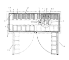
図1〜5に本発明の実施例を示す。
本装置の本体は、箱型形状の外観を有し、本体内側側面Cおよび側面Dには試料容器1を起立保持するためのラック2を、多数収納するための棚A9と棚B10とがそれぞれ設置され、その内の棚A9は、図2に示すように側面Cに設けられた左扉13、右扉14上に設けられている。
棚A9と棚B10との間には本装置内を上下左右移動することのできる移動装置を有した搬送部4が設けられている。
【0011】
この搬送部4には、図3に示すように棚A9および棚B10のどちらからもラック2を取出すことのできる2つのラック引出機構A11とラック引出機構B12とを備え、且つラック引出し機構によって引出されたラック2に収納されている試料容器1を、受取ラック11に詰替えるための搬送部4上を前後左右に移動可能なピッカー8ら構成されている詰替部5が搭載されている。
なお、ピッカー8は、ハンドアームと呼ばれる試料容器1を掴むための部材が複数本開閉自在に設けてあり、この部材を使って試料容器1を掴むことができる。装置の動作制御、試料容器1よびラック2棚内の位置情報はすべて制御部6によって管理されている。
【0012】
本装置の形態による試料容器1およびラック2の位置情報の入力方法について説明する。
試料容器1の容器底には予めバーコードが取付けられており、ラック2に保持されたまま図示されていないバーコードリーダで試料容器1各々の情報と、ラック2のどの位置に各々の試料容器1が収納されているかを読込み、制御部6内の図示されていない記憶装置に記憶する。また、ラック2の側面にもバーコードが取付けられて要るので、ラック2のバーコードのデータを図示していないバーコードリーダを使って読込み制御部6内の図示されていない記憶装置に記憶しておく。
【0013】
ラック2毎の試料容器1の情報を記憶した後、ラック2を左扉13、右扉14をあけ、棚A9、棚B10の任意の位置にセットしていく。左扉13、右扉14に棚A9を設けてあるので扉を開けることで奥の棚B10にも直接収納することができる。
ラック2を棚A9、棚B10に入れ終ったら左扉13、右扉14を閉め、搬送部4に取付てあるバーコードリーダ15で本装置内の全てのラック2の側面にあるバーコードのデータを読み取り、本装置内の棚A9および棚B10のどの位置に、どのラック2が収納されているか、制御部6内の図示されていない記憶装置に記憶させる。こうすることにより、試料容器1およびラック2の棚内の位置情報は全て制御部6によって管理することができ、また、任意の位置にラック2をセットすることができるので、大量の試料容器を迅速に格納することができる。
【0014】
試料容器1回収する為の受取ラック7も同様にバーコードを取付けておき、棚A9および棚B10の任意の位置にセットしておき、搬送部4に取付けてあるバーコードリーダ15でデータを読み取り、制御部6内の図示されていない記憶装置に記憶させる。
この様な構成にすることにより、受取ラック7の収納位置と受取ラック7の数量を任意に設定することができる。本実施例では受取ラック7に取付けたバーコードによって、受取ラックの位置と個数を把握しているが、他の方法として制御部6に直接受取ラック7の位置と数量の情報を入力することも可能である。
【0015】
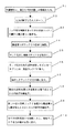
次に、本実施例の試料容器1の取出方法について説明する。
初めに、制御部6に接続されている図示されていない入力装置を使って、取出したい試料容器のデータを入力する。(S1)
情報の入力が終了したらスタートさせる。(S2)
搬送部4は移動装置により本装置内に設置されている空の受取ラック7(空ラック)の前に移動し、ラック引出機構B12を使って受取ラック7を搬送機4上に引出す。(S3)
ラックの引出し方は、搬送機4が目的のラックの前まで移動し、ラック引出機構部の図示していないスライドアームがスライドし、スライドアームがラックの下に入り込む。次に、スライドアームが僅かに上方に移動し、ラックを棚から僅かに浮かす。ラックが浮いたら、スライドアームをスライドさせ、ラックを搬送部4に引出すことができる。
また、上記した方法以外にスライドアームにラックを引出す為の爪を設けることにより、ラックを持上げることなく、棚上をスライドすることもできる。
受取ラック7を搬送機4上に引出したら、搬送機4は移動装置により取出すよう指示された試料容器1が入っているラック2の前に移動する。(S4)
目的のラック2までの移動が終了すると、搬送部4に設けてあるもう一つのラック引出機構A11を使ってラック2を搬送機4上まで引出す。(S5)
ピッカー8は制御部6の指示により指定された試料容器1をつかみラック2から取出し、受取ラック7に移しかえる。(S6)
移し変えが完了すると、ラック引出機構A11が引出したラック2を元の棚に戻す(S7)
尚、取出す試料容器1が複数ある場合は、(S4)からの動作を繰返す(S8)指示された試料容器1の数が多く一つの受取ラック7では収納しきれない場合は、いっぱいになった、受取ラックを元の棚に戻し、新たに空の受取ラック7を搬送機4上に移し替え、(S4)からの動作を繰返す。(S9)
指示された全ての試料容器1がそろったら、搬送機4上の受取ラック7を元の棚の位置に戻す。(S10)
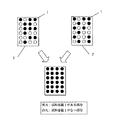
また、本実施例のように構成することにより、図8に記載したように試料容器1をラック2から他のラック2に載せかえることができる。
図5に示すように、詰替えを行いたい2つのラック2をラック引出機構A11とラック引出機構B12を使って、搬送部4上に引出し、片方のラック2にピッカー8を使って試料容器1を載せ替える。
載せ替えが終わったら、引出されたラック2は元の位置に戻される。(なお、空になったラック2は、図示されていないラック回収部に回収されるようにしても良い。また、受取ラックとして使用しても良い。)
また、図9に記載したように、一つのラック2内で、散在した状態で収納されていたものを、ラック引出機構を使って、搬送部4上に引出しピッカー8を使って整頓することもでき、本装置内のスペースを有効に利用することができ、従来の装置より小型化が可能となる。
【0016】
また、本装置では少量の試料容器1を収納することもできる。受取ラック7に保管したい試料容器1を入れ、図示しないバーコードリーダで試料容器1の情報を読込んだのち、本装置内の受取ラック置場に前記ラック2を置く。次に、制御部6に少量の試料容器1を保管することを入力する。搬送部4に設けてあるラック引出機構B12が受取ラック置場に置いてある受取ラック7を搬送部4上に引出す。制御部6は、本装置内の個々のラック2の試料容器1の収納状態を把握しているので、搬送部4は試料容器1を収納するスペースが有るラック2まで移動し、棚A3又は棚B4に収納されているラック2をラック引出し機構A11を使って搬送部4上まで引出す。ラック2を引出したらピッカー8により、試料容器1を受取ラック7からラック2に移し変える。尚、上記動作は、ラック引出機構A11およびラック引出機構B12の関係が逆になっても同様の動作が行える。以上のことから、本装置内のスペースを有効に利用することができ、従来の装置より小型化が可能となる。
【0017】
上記のような構成にすることにより、図6に示すような従来技術の回転式の保管部程度の大大きさになる。
また、詰替部6が棚の間を移動し必要なラック2の位置で試料容器1を受取ラック11に詰替えられるので、試料容器1の取出しのたびにラック2を詰替部6まで移動しなければならない従来技術にくらべ短時間で試料容器の詰替えが行える。
【0018】
また、温度管理が必要な試料の場合には装置内に温度調整手段を搭載することで温度管理が出来る。
また、外装部17および左扉13、右扉14をパンチメタルのような通気性のあるものにすれば、温度調整の出来る部屋(例えば恒温室)に入れることで試料容器1の温度管理ができ、既存の温度調整の出来る部屋に入れることで新たに自動保管装置のためのスペースを確保しなくてもすむ。
【0019】
また、移動可能手段であるキャスター20を取り付けることで、必要に応じて移動することが出来利便性が高い。
【0020】
【発明の効果】
本発明によれば次の効果を得ることができる。
(1)保管部に扉をもうけ直接棚にセットできるようにしたことと、ラック引き出し機構を2搭載したことで保管用の棚を受け取りラック置き場として使用できるようになり取り出す試料容器の本数を任意に指定できる。
(2)引き出し機構を2つ搭載したのでラック間での試料容器の詰替えが可能になり保管部内で散在する試料容器を必要最小限のラックにまとめることが出来る。
(3)扉内壁に棚を設けたので奥側の棚にもアクセスできる。
【図面の簡単な説明】
【図1】は本発明の正面図である。
【図2】は本発明の上面断面図である。
【図3】は本発明の搬送部側面面図である。
【図4】は本発明のラックから受け取りラックへ詰め替える時の上面断面図である。
【図5】は本発明のラックからラックに詰め替える時の上面断面図である。
【図6】は従来技術の上面図である。
【図7】は従来技術の正面図である。
【図8】は本実施例のステップ図
【図9】は2つのラックに散在した試料容器を1つにまとめる、モデル図
【図10】は散在した試料容器を整頓するモデル図
【符号の説明】
1は試料容器、2はラック、3は保管部、4は搬送部、5は詰替部、6は制御部、7は受取ラック、8はピッカー、9は棚A、10は棚B、11は引出し機構A、12は引出し機構B、13は左扉、14右扉、15はバーコードリーダ、16は受け取りラック置場、17は外装部、20はキャスターである。[0001]
[Industrial applications]
The present invention is a medical, pharmacy, agriculture, clinical, biology and other various fields related to biotechnology, such as blood, enzymes, genes, compounds, reagents while storing and managing a large amount of useful sample containers The present invention relates to an automatic storage device capable of automatically taking a sample container in and out.
[0002]
[Prior art]
With the technological innovations in various fields related to biotechnology such as medicine, pharmacy, agriculture, clinical science, and biology, the work of handling many samples has increased rapidly, and it has become important to store and manage these samples. Is coming. FIGS. 6 and 7 show an apparatus for automating these operations. FIG. 6 is a top view of the prior art, and FIG. 7 is a front view of the prior art. The apparatus includes a storage unit 3 for storing a sample container 1 in a rack 2 for storage, a transport unit 4 for extracting the rack 2 from the storage unit 3, and a refill unit 5 for extracting a required sample container 1 from the rack 2. . Each part is arbitrarily arranged and sometimes even covers the entire room.
[0003]
These three parts operate according to commands from the control unit 6 to move the sample container 1 in the storage unit 3 to the receiving rack 7 or to store the sample container 1 in the storage unit 3 by following the reverse process. .
When the sample container 1 to be taken out is specified in the control unit 6, the storage unit 3 is rotated and moved to a position where the transport unit 4 can take out the necessary rack 2 based on the positional information of the rack 2 and the sample container 1 in the storage unit 3. I do. The transport unit 4 removes the rack 2 from the storage unit 3 and moves the rack 2 to the refill unit 5. The picker 8 of the refill unit 5 takes out only the necessary sample container 1 from the rack 2. Thereafter, the rack 2 is returned to the storage unit 3 by the transport unit 4. This operation is repeated for the required number of samples to complete the operation. When storing the sample container 1, the reverse process is followed.
[0004]
An automatic rotating shelf is used as a means of the storage unit 3. An arm robot, a belt conveyor, or the like is used as the means of the transport unit 4. The refilling unit 5 mainly uses a mechanism called a picker 8 for picking up the sample container 1 and moving it to the receiving rack 7.
[0005]
[Problems to be solved by the invention]
In the automatic machine described above, the number of sample containers that can be taken out in one operation is limited to the capacity of the receiving rack 7. Although the number can be increased by using a plurality of receiving racks 7, the number of receiving racks 7 is usually limited to the space of a storage unit for storing the receiving racks 7. Furthermore, if the number of the receiving racks 7 is to be flexibly adjusted, the receiving racks 7 may be automatically supplied by a robot, but this is a large-scale facility and is not practical.
[0006]
In addition, since the sample containers 1 of the storage unit 3 are scattered in each rack 2 while being used many times, the racks 2 need to be used more than necessary. As a means for this, it is conceivable to manually refill all the sample containers in the storage unit 3, but the data for storage management is destroyed.
[0007]
If the sample containers 1 are to be automatically refilled, the storage unit 3 is rotated and moved to a position where the transport unit 4 can take out the necessary rack 2. The transport unit 4 removes the rack 2 from the storage unit 3 and moves the rack 2 to the refill unit 5. The picker 8 of the refilling unit 5 needs a very complicated process of once moving the sample container 1 from the rack 2 to the receiving rack 7 and moving another rack 2 from the storage unit 3 to the refilling unit 5 for refilling. It is not realistic.
[0008]
Furthermore, when storing a small number of sample containers in the storage device, it is sufficient to store them one by one by the above-described method. However, when storing a large number of sample containers at one time such as initial setting, it takes an enormous amount of time. .
Therefore, the problem to be solved by the present invention is (1) that the number of sample containers to be taken out can be set arbitrarily.
(2) Able to automatically organize the storage section.
(3) A large amount of sample containers can be stored quickly.
It is.
[0009]
[Means for Solving the Problems]
The above-described problem is achieved by unifying the storage unit, the transfer unit, and the refill unit, which are independent of the three parts, by arranging the shelves of the storage unit in two rows and arranging the transfer unit and the refill unit between the shelves. Can be achieved.
Further, in the case of a sample requiring temperature control, the temperature of the sample can be controlled by installing a means for adjusting the temperature in the apparatus. In addition, the temperature of the sample can be controlled by placing it in an environment in which the temperature can be controlled by using an exterior that does not cause a temperature difference between the inside and the outside of the apparatus without mounting a means for adjusting the temperature.
Further, the problem can be solved by providing a plurality of rack pull-out mechanisms and providing a door capable of directly accessing the rack in the storage unit.
Furthermore, the door on the opposite side can be accessed by providing a door inner wall shelf.
[0010]
BEST MODE FOR CARRYING OUT THE INVENTION
1 to 5 show an embodiment of the present invention.
The main body of the present apparatus has a box-shaped appearance, and a rack A9 and a shelf B10 for accommodating a large number of racks 2 for holding the sample container 1 upright are provided on the inner side surface C and the side surface D, respectively. The shelves A9 are installed, and the shelves A9 are provided on the left door 13 and the right door 14 provided on the side surface C as shown in FIG.
Between the shelf A9 and the shelf B10, a transport unit 4 having a moving device capable of moving up, down, left, and right in the present apparatus is provided.
[0011]
As shown in FIG. 3, the transport unit 4 includes two rack pull-out mechanisms A11 and B12 that can take out the rack 2 from both the shelves A9 and B10. A refill unit 5 including a picker 8 that can move forward, backward, left and right on a transport unit 4 for refilling the sample container 1 stored in the rack 2 into a receiving rack 11 is mounted.
The picker 8 is provided with a plurality of members called hand arms for gripping the sample container 1 so as to be freely opened and closed. The member can be used to grip the sample container 1. The operation control of the apparatus and the position information in the sample container 1 and the rack 2 are all managed by the control unit 6.
[0012]
A method for inputting the position information of the sample container 1 and the rack 2 according to the form of the present apparatus will be described.
A bar code is attached to the bottom of the container of the sample container 1 in advance. The bar code reader (not shown) holds the information of each sample container 1 and the position of each sample container in the rack 2 while being held in the rack 2. 1 is read and stored in a storage unit (not shown) in the control unit 6. Further, since a bar code is also required to be attached to the side surface of the rack 2, the bar code data of the rack 2 is stored in a storage device (not shown) in the reading control unit 6 using a bar code reader (not shown). Keep it.
[0013]
After storing the information of the sample container 1 for each rack 2, the left door 13 and the right door 14 are opened, and the rack 2 is set at an arbitrary position on the shelf A9 and the shelf B10. Since the left door 13 and the right door 14 are provided with shelves A9, by opening the doors, the shelves A9 can be directly stored in the back shelf B10.
When the rack 2 has been placed in the shelves A9 and B10, the left door 13 and the right door 14 are closed, and the bar code reader 15 attached to the transport unit 4 reads the bar code data on the side of all the racks 2 in the apparatus. Is read, and which rack 2 is stored in which position of the shelf A9 and the shelf B10 in the apparatus is stored in a storage device (not shown) in the controller 6. By doing so, the position information of the sample container 1 and the rack 2 in the shelf can all be managed by the control unit 6, and the rack 2 can be set at an arbitrary position. Can be stored quickly.
[0014]
Similarly, a bar code is attached to the receiving rack 7 for collecting the sample container 1, the bar code is set at an arbitrary position on the shelf A 9 and the shelf B 10, and data is read by the bar code reader 15 attached to the transport unit 4. Are stored in a storage device (not shown) in the control unit 6.
With such a configuration, the storage position of the receiving rack 7 and the quantity of the receiving rack 7 can be arbitrarily set. In this embodiment, the position and the number of the receiving racks are grasped by the barcode attached to the receiving rack 7. However, as another method, the information on the position and the number of the receiving racks 7 can be directly input to the control unit 6. It is possible.
[0015]
Next, a method for removing the sample container 1 according to the present embodiment will be described.
First, data of a sample container to be taken out is input using an input device (not shown) connected to the control unit 6. (S1)
Start when you have finished entering information. (S2)
The transport unit 4 is moved by the moving device to an empty receiving rack 7 (empty rack) installed in the apparatus, and pulls the receiving rack 7 onto the transporting machine 4 using the rack pull-out mechanism B12. (S3)
With respect to the way of pulling out the rack, the transporter 4 moves to the front of the target rack, the slide arm (not shown) of the rack pull-out mechanism slides, and the slide arm enters under the rack. Next, the slide arm moves slightly upward, causing the rack to float slightly off the shelf. When the rack floats, the slide arm can be slid and the rack can be pulled out to the transport section 4.
In addition, by providing a claw for pulling out the rack on the slide arm other than the above-described method, it is possible to slide on the shelf without lifting the rack.
When the receiving rack 7 is pulled out onto the transporter 4, the transporter 4 moves to the front of the rack 2 containing the sample container 1 instructed to be removed by the moving device. (S4)
When the movement to the target rack 2 is completed, the rack 2 is pulled out onto the transporter 4 by using another rack pull-out mechanism A11 provided in the transport unit 4. (S5)
The picker 8 takes out the sample container 1 specified by the instruction of the control unit 6 from the grasping rack 2 and transfers it to the receiving rack 7. (S6)
When the transfer is completed, the rack 2 pulled out by the rack pull-out mechanism A11 is returned to the original shelf (S7).
If there are a plurality of sample containers 1 to be taken out, the operation from (S4) is repeated (S8). If the number of designated sample containers 1 is too large to be accommodated in one receiving rack 7, it is full. Then, the receiving rack is returned to the original shelf, a new empty receiving rack 7 is transferred onto the transporter 4, and the operation from (S4) is repeated. (S9)
When all the specified sample containers 1 are collected, the receiving rack 7 on the transporter 4 is returned to the original shelf position. (S10)
Further, by configuring as in the present embodiment, the sample container 1 can be changed from the rack 2 to another rack 2 as shown in FIG.
As shown in FIG. 5, two racks 2 to be refilled are pulled out onto the transport section 4 using a rack pull-out mechanism A11 and a rack pull-out mechanism B12, and a sample container 1 is loaded into one of the racks 2 using a picker 8. Replace.
When the reloading is completed, the pulled-out rack 2 is returned to the original position. (Note that the empty rack 2 may be collected by a rack collection unit (not shown). Alternatively, the rack 2 may be used as a receiving rack.)
Further, as shown in FIG. 9, what is stored in a scattered state in one rack 2 may be arranged on the transport unit 4 by using a rack pull-out mechanism using a drawer picker 8. Thus, the space in the present apparatus can be effectively used, and the size can be reduced as compared with the conventional apparatus.
[0016]
In this apparatus, a small amount of the sample container 1 can be stored. The sample container 1 to be stored is placed in the receiving rack 7, the information of the sample container 1 is read by a bar code reader (not shown), and then the rack 2 is placed in the receiving rack place in the apparatus. Next, the controller 6 inputs that a small amount of the sample container 1 is to be stored. A rack pull-out mechanism B12 provided in the transport unit 4 pulls out the receiving rack 7 placed in the receiving rack place onto the transport unit 4. Since the control unit 6 has grasped the storage state of the sample containers 1 in the individual racks 2 in the present apparatus, the transport unit 4 moves to the rack 2 having a space for storing the sample containers 1 and the shelf A3 or the shelf A3. The rack 2 stored in B4 is pulled out onto the transport unit 4 using the rack pullout mechanism A11. When the rack 2 is pulled out, the sample container 1 is transferred from the receiving rack 7 to the rack 2 by the picker 8. The same operation can be performed even if the relationship between the rack pull-out mechanism A11 and the rack pull-out mechanism B12 is reversed. From the above, the space in the present apparatus can be effectively used, and the size can be reduced as compared with the conventional apparatus.
[0017]
With the above configuration, the size becomes as large as that of the conventional rotary storage unit as shown in FIG.
In addition, since the refill unit 6 moves between the shelves and refills the sample containers 1 to the receiving racks 11 at the required positions of the racks 2, the rack 2 is moved to the refill unit 6 each time the sample containers 1 are taken out. The sample container can be refilled in a shorter time than the prior art that must be performed.
[0018]
In the case of a sample requiring temperature control, the temperature can be controlled by mounting a temperature adjusting means in the apparatus.
In addition, if the exterior part 17 and the left and right doors 13 and 14 are made of air-permeable material such as punch metal, the temperature of the sample container 1 can be controlled by placing the room in a temperature-controllable room (for example, a constant temperature room). In addition, it is not necessary to newly secure a space for an automatic storage device by placing the device in an existing temperature-controllable room.
[0019]
In addition, by attaching the casters 20 which are movable means, it is possible to move as necessary and the convenience is high.
[0020]
【The invention's effect】
According to the present invention, the following effects can be obtained.
(1) The storage section has a door so that it can be set directly on shelves, and two rack drawers can be used to receive storage shelves so that it can be used as a rack storage area, and the number of sample containers to be taken out is arbitrary. Can be specified.
(2) Since two drawer mechanisms are mounted, the sample containers can be refilled between racks, and the sample containers scattered in the storage unit can be collected in a minimum number of racks.
(3) Since shelves are provided on the inner wall of the door, the shelves on the back side can be accessed.
[Brief description of the drawings]
FIG. 1 is a front view of the present invention.
FIG. 2 is a top sectional view of the present invention.
FIG. 3 is a side view of a transport unit according to the present invention.
FIG. 4 is a top cross-sectional view of the present invention when refilling from a rack to a receiving rack.
FIG. 5 is a top sectional view when refilling from a rack to a rack according to the present invention.
FIG. 6 is a top view of the prior art.
FIG. 7 is a front view of the prior art.
FIG. 8 is a step diagram of the present embodiment. FIG. 9 is a model diagram for unifying sample containers scattered in two racks into one. FIG. 10 is a model diagram for organizing sample containers scattered. ]
1 is a sample container, 2 is a rack, 3 is a storage unit, 4 is a transport unit, 5 is a refill unit, 6 is a control unit, 7 is a receiving rack, 8 is a picker, 9 is shelf A, 10 is shelf B, 11 Is a drawer mechanism A, 12 is a drawer mechanism B, 13 is a left door, 14 right door, 15 is a bar code reader, 16 is a receiving rack place, 17 is an exterior part, and 20 is a caster.