JP3882714B2 - Automatic storage device - Google Patents
Automatic storage device Download PDFInfo
- Publication number
- JP3882714B2 JP3882714B2 JP2002241131A JP2002241131A JP3882714B2 JP 3882714 B2 JP3882714 B2 JP 3882714B2 JP 2002241131 A JP2002241131 A JP 2002241131A JP 2002241131 A JP2002241131 A JP 2002241131A JP 3882714 B2 JP3882714 B2 JP 3882714B2
- Authority
- JP
- Japan
- Prior art keywords
- rack
- sample container
- automatic storage
- unit
- shelf
- Prior art date
- Legal status (The legal status is an assumption and is not a legal conclusion. Google has not performed a legal analysis and makes no representation as to the accuracy of the status listed.)
- Expired - Fee Related
Links
Images


Classifications
-
- G—PHYSICS
- G01—MEASURING; TESTING
- G01N—INVESTIGATING OR ANALYSING MATERIALS BY DETERMINING THEIR CHEMICAL OR PHYSICAL PROPERTIES
- G01N35/00—Automatic analysis not limited to methods or materials provided for in any single one of groups G01N1/00 - G01N33/00; Handling materials therefor
- G01N35/0099—Automatic analysis not limited to methods or materials provided for in any single one of groups G01N1/00 - G01N33/00; Handling materials therefor comprising robots or similar manipulators
-
- B—PERFORMING OPERATIONS; TRANSPORTING
- B65—CONVEYING; PACKING; STORING; HANDLING THIN OR FILAMENTARY MATERIAL
- B65G—TRANSPORT OR STORAGE DEVICES, e.g. CONVEYORS FOR LOADING OR TIPPING, SHOP CONVEYOR SYSTEMS OR PNEUMATIC TUBE CONVEYORS
- B65G1/00—Storing articles, individually or in orderly arrangement, in warehouses or magazines
- B65G1/02—Storage devices
- B65G1/04—Storage devices mechanical
- B65G1/0407—Storage devices mechanical using stacker cranes
- B65G1/0435—Storage devices mechanical using stacker cranes with pulling or pushing means on either stacking crane or stacking area
-
- B—PERFORMING OPERATIONS; TRANSPORTING
- B65—CONVEYING; PACKING; STORING; HANDLING THIN OR FILAMENTARY MATERIAL
- B65G—TRANSPORT OR STORAGE DEVICES, e.g. CONVEYORS FOR LOADING OR TIPPING, SHOP CONVEYOR SYSTEMS OR PNEUMATIC TUBE CONVEYORS
- B65G1/00—Storing articles, individually or in orderly arrangement, in warehouses or magazines
- B65G1/02—Storage devices
- B65G1/04—Storage devices mechanical
- B65G1/137—Storage devices mechanical with arrangements or automatic control means for selecting which articles are to be removed
- B65G1/1373—Storage devices mechanical with arrangements or automatic control means for selecting which articles are to be removed for fulfilling orders in warehouses
- B65G1/1378—Storage devices mechanical with arrangements or automatic control means for selecting which articles are to be removed for fulfilling orders in warehouses the orders being assembled on fixed commissioning areas remote from the storage areas
-
- G—PHYSICS
- G01—MEASURING; TESTING
- G01N—INVESTIGATING OR ANALYSING MATERIALS BY DETERMINING THEIR CHEMICAL OR PHYSICAL PROPERTIES
- G01N35/00—Automatic analysis not limited to methods or materials provided for in any single one of groups G01N1/00 - G01N33/00; Handling materials therefor
- G01N35/02—Automatic analysis not limited to methods or materials provided for in any single one of groups G01N1/00 - G01N33/00; Handling materials therefor using a plurality of sample containers moved by a conveyor system past one or more treatment or analysis stations
- G01N35/04—Details of the conveyor system
- G01N2035/0401—Sample carriers, cuvettes or reaction vessels
- G01N2035/0418—Plate elements with several rows of samples
- G01N2035/042—Plate elements with several rows of samples moved independently, e.g. by fork manipulator
-
- G—PHYSICS
- G01—MEASURING; TESTING
- G01N—INVESTIGATING OR ANALYSING MATERIALS BY DETERMINING THEIR CHEMICAL OR PHYSICAL PROPERTIES
- G01N35/00—Automatic analysis not limited to methods or materials provided for in any single one of groups G01N1/00 - G01N33/00; Handling materials therefor
- G01N35/02—Automatic analysis not limited to methods or materials provided for in any single one of groups G01N1/00 - G01N33/00; Handling materials therefor using a plurality of sample containers moved by a conveyor system past one or more treatment or analysis stations
- G01N35/04—Details of the conveyor system
- G01N2035/0401—Sample carriers, cuvettes or reaction vessels
- G01N2035/0418—Plate elements with several rows of samples
- G01N2035/0425—Stacks, magazines or elevators for plates
-
- G—PHYSICS
- G01—MEASURING; TESTING
- G01N—INVESTIGATING OR ANALYSING MATERIALS BY DETERMINING THEIR CHEMICAL OR PHYSICAL PROPERTIES
- G01N35/00—Automatic analysis not limited to methods or materials provided for in any single one of groups G01N1/00 - G01N33/00; Handling materials therefor
- G01N35/02—Automatic analysis not limited to methods or materials provided for in any single one of groups G01N1/00 - G01N33/00; Handling materials therefor using a plurality of sample containers moved by a conveyor system past one or more treatment or analysis stations
- G01N35/028—Automatic analysis not limited to methods or materials provided for in any single one of groups G01N1/00 - G01N33/00; Handling materials therefor using a plurality of sample containers moved by a conveyor system past one or more treatment or analysis stations having reaction cells in the form of microtitration plates
Description
【0001】
【産業上の利用分野】
本発明は、医学、薬学、農学、臨床、生物学等バイオ技術に関連するさまざまな分野で、血液、酵素、遺伝子、化合物、試薬など大量の有用な試料を入れた試料容器を保管管理するとともに、試料容器を自動的に出し入れできる自動保管装置に関する。
【0002】
【従来の技術】
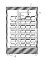
医学、薬学、農学、臨床、生物学等バイオ技術に関連するさまざまな分野の技術革新に伴い、迅速にかつ数多くの試料を扱う作業が増加し、それら試料の保管管理をすることが重要視されてきている。これらの作業を自動化する装置として図5、6に示すものがある。図5は従来技術の上面図、図6は従来技術の正面図である。この装置は、試料の入った試料容器1をラック2に入れ保管する保管部分12と、保管部12よりラック2を取り出す搬送部5、ラック2から必要な試料容器1を取り出す詰替部6から構成されている。各部は任意に配置され、時には部屋全体に及ぶこともある。
【0003】
これら3つの部分が制御部10からの指令により動作し、保管部12にある試料容器1を受取ラック11まで移動したり、逆の工程をたどって試料容器1を保管部12に収納したりする。
【0004】
制御部10に取出したい試料容器1を指定すると、保管部12内におけるラック2および試料容器1の位置情報をもとに、保管部12が必要なラック2を搬送部5が取り出せる位置に回転移動する。搬送部5はラック2を保管部12より取だし詰替部6にラック2を移動する。詰替部6のピッカー9はラック2から必要な試料容器1のみを取出す。その後ラック2は搬送部5により保管部12に戻される。この操作を必要試料数分繰り返し作業は完了する。また、試料容器1を収納する場合はこの逆の工程をたどる。
【0005】
保管部12の手段としては自動回転棚が用いられている。搬送部5の手段としてはアームロボットやベルトコンベアなどが用いられる。詰替部6は主にピッカー9と呼ばれる試料容器1を摘み上げて受取ラック11へ移動する機構が使われている。
【0006】
【発明が解決しようとする課題】
以上のような自動機はもともと工業用の自動倉庫からは発展したものであり部屋全体を使うような大型のものが主流である。医学、薬学、農学、臨床、生物学等の分野では大きすぎ、その用途は製薬会社の化合物保存庫などごく一部に限られている。また、小型のものも開発されているが当該分野で小型と言えるほど小さくはない。
【0007】
また、保管部、搬送部、詰替部と分かれているため、試料容器を取出す度にラックを保管部から詰替部まで移動してこなければならず取出しに時間を要していた。
このようなことから、本発明が解決しようとする課題は
(1) コンパクトサイズの自動機を提供すること。
(2) 迅速に試料容器の詰替えが行えること。
である。
【0008】
【課題を解決するための手段】
上記課題は、3部分に独立している保管部、搬送部、詰替部を、保管部の棚を2列に配置し、棚の間に搬送部と、詰替部を配置して一体化することで達成できる。
さらに、温度管理が必要な試料の場合、装置内の温度を調整する手段を搭載することで試料の温度管理が出来る。また、温度調整をする手段を搭載しなくとも装置内外の温度差が生じない外装にして温度管理が出来る環境におくことで試料の温度管理が出来る。
【0009】
【発明の実施の形態】
図1〜4に本発明の実施例を示す。
本発明の実施の形態を図1〜図4にもとづき説明する。
本装置の本体は、箱型形状の外観を有し、本体内側側面Cおよび側面Dには試料容器1を起立保持するためのラック2を、多数収納するための棚A3と棚B4とがそれぞれ設置され、棚A3と棚B4と間には本装置内を上下左右移動することのできる移動装置を有した搬送部5が設けられている。この搬送部5には、棚A3および棚B4のどちらからもラック2を取出せるラック引出し機構8と、受取ラック置場7とラック引出し機構8によって引出されたラック2に収納されている試料容器1を受取ラック11に詰替えるための搬送部5上を前後左右に移動可能なピッカー9から構成されている詰替部6が搭載されている。なお、ピッカー9には、ハンドアームと呼ばれる試料容器1を掴むための部材が複数本開閉自在に設けてあり、この部材を使って試料容器1を掴むことができる。
【0010】
尚、取出したい試料容器1の情報入力や、搬送部5の動作制御、ピッカーのハンドアームの動作制御や、試料容器1およびラック2の棚内の位置情報はすべて制御部10によって管理されている。
【0011】
本実施の形態による試料容器1およびラック2の位置情報の入力方法について説明する。試料容器1の容器底には予めバーコードが取付けられ、ラック2に保持されたまま図示されていないバーコードリーダで試料容器1各々の情報と、ラック2のどの位置に各々の試料容器1が収納されているかを読込み、制御部10内の図示されていない記憶装置に記憶される。ラック2毎の試料容器1の情報を記憶した後、搬送部5上のラック引出し機構部8にラック2を載せ、棚A3、棚B4に収納する。このとき、ラック2を棚A3、棚B4のどの位置に収納したかを制御部10の図示されていない記憶装置に記憶させることにより、試料容器1およびラック2の棚内の位置情報は全て制御部10によって管理することができる。
【0012】
次に、図1、図2、図7を使って試料容器1の取出方法について説明する。
搬送部5は、図1、2に示すように、ホームポジションと呼ばれる位置でスタンバイしている。このホームポジションの位置では、搬送部5の一部が外装部14に設けてある取出口13から外部に一部分飛び出す構造になっていて、こうすることにより、外装部14を開口することなく受取ラック11を搬送部5上に設けてある受取ラック置場7に置くことができる。
この状態で試料容器1を起立保持することのできる空の受取ラック11を受取ラック置場7に置き、制御部10に取出す試料容器1の情報を入力する(S1)。情報の入力が終了したらスタートさせる(S2)。
図3、図4に示すように、搬送部5は移動装置により指示された試料容器1が入っているラック2の前に移動する(S3)。
目的のラック2までの移動が終了すると、搬送部5に設けてあるラック引出し機構8がラック2を搬送部5まで引出す(S4)。
ピッカー9は制御部10の指示により指定された試料容器1を掴みラック2から取出し、受取ラック11に移し替える(S5)。
移し替えが完了すると、ラック引出し機構8が引出されたラック2を元の棚にもどす。(S6)
尚、取出す試料容器1が複数ある場合は、(S3)からの動作を繰返す(S7)。
指示された全ての試料容器1が全てそろったら、搬送部5はホームポジションの位置にもどる(S8)。
【0013】
また、本実施例のように構成することにより、図8に記載したように試料容器1をラック2から他のラック2に詰替えることができる。
詰替たい試料容器1があるラック2の場所に、受取ラック11を載せた搬送部5が移動し、ラック2をラック引出し機構8によって引出す。引出されラック2に収納されている試料容器1を全て受取ラック11に移しかえる。空になったラック2は元の戻される。(空になったラック2は図示されていないラック回収箱に回収されるようにしても良い。)
次に、搬送部5は載せ変えたいラック2の位置まで移動し、ラック引出し機構8によって引出す。引出されたラック2に先ほど受取ラック11に移し変えた試料容器1を載せかえる。
また、図9に記載したように、一つのラック2内で、歯抜け状態で収納されていたものを、整頓することができ、本装置内のスペースを有効に利用することができ、従来の装置より小型化が可能となる。
【0014】
また、本装置では少量の試料容器1を収納することができる。ラック11に保管したい試料容器1を入れ、図示しないバーコードリーダで試料容器1の情報を読込んだのち、搬送部5上に設けてある受取ラック置場7に前記ラック2を置く。次に、制御部10に少量の試料容器1を保管することを入力する。制御部10は、個々のラック2の収納状態を把握しているので、搬送部5は試料容器1を収納するスペースが有るラック2まで移動し、棚A3又は棚B4に収納されているラック2をラック引出し機構8を使って搬送部5上まで引出す。ラック2を引出したらピッカー9により、試料容器1を受取ラック11からラック2に移し変える。
このような動作は、本装置内のスペースを有効に利用することができ、従来の装置より小型化が可能となる。
【0015】
上記のような構成にすることにより、図5に示すような従来技術の回転式の保管部程度の大きさになる。
また、詰替部6が棚の間を移動し必要なラック2の位置で試料容器1を受取ラック11に詰替えられるので、試料容器1の取出しのたびにラック2を詰替部6まで移動しなければならない従来技術にくらべ短時間で試料容器の詰替えが行える。
また、温度管理が必要な試料の場合には装置内に温度調整手段を搭載することで温度管理が出来る。
【0016】
また、外装部14をパンチメタルのような通気性のあるものにすれば、温度調整の出来る部屋(例えば恒温室)に入れることで試料容器1の温度管理ができ、既存の温度調整の出来る部屋に入れることで新たに自動保管装置のためのスペースを確保しなくてもすむ。
【0017】
また、移動可能手段であるキャスター15を取り付けることで、必要に応じて移動することが出来利便性が高い。
【0018】
【発明の効果】
本発明によれば次の効果を得ることができる。
(1)保管部、搬送部、詰替部を一体にしたので小型化が図れる。
(2)管部、搬送部、詰替部を一体にしたのでラックが収納されている場所で試料容器の詰替えができるので従来技術のようにラックを詰替部まで搬送して試料容器を詰替える方法に比べ迅速に試料容器の詰替えができる。
(3)温度調整手段を搭載することで試料の温度管理が出きる。
(4)装置内外の温度差が生じない外装にすることで、温度調整機能を有する環境におくことで試料の温度管理ができる。
【図面の簡単な説明】
【図1】は本発明のホームポジションの正面断面図である。
【図2】は本発明のホームポジションの上面断面図である。
【図3】は本発明の試料容器移動時の正面断面図である。
【図4】は本発明の試料容器移動時の上面断面図である。
【図5】は従来技術の上面図である。
【図6】は従来技術の正面図である。
【図7】は本実施例のステップ図
【図8】は2つの散在した試料容器を1つにまとめる、モデル図
【図9】は散在した試料容器を整頓するモデル図
【符号の説明】
1は試料容器、2はラック、3は棚A、4は棚B、5は搬送部、6は詰替部、7は受取ラック置場、8はラック引出し機構、9はピッカー、10は制御部、11は受取ラック、12は保管部、13は取出口、14は外装部、15はキャスターである。[0001]
[Industrial application fields]
The present invention stores and manages a sample container containing a large amount of useful samples such as blood, enzymes, genes, compounds, and reagents in various fields related to biotechnology such as medicine, pharmacy, agriculture, clinical practice, and biology. The present invention relates to an automatic storage device capable of automatically taking in and out a sample container.
[0002]
[Prior art]
Along with technological innovation in various fields related to biotechnology such as medicine, pharmacy, agriculture, clinical practice, biology, etc., the work to handle a large number of samples quickly has increased, and it is important to store and manage these samples. It is coming. An apparatus for automating these operations is shown in FIGS. FIG. 5 is a top view of the prior art, and FIG. 6 is a front view of the prior art. This apparatus includes a storage part 12 for storing a
[0003]
These three parts operate in response to a command from the control unit 10 to move the
[0004]
When the control unit 10 designates the
[0005]
An automatic rotating shelf is used as means for the storage unit 12. An arm robot, a belt conveyor, or the like is used as a means for the
[0006]
[Problems to be solved by the invention]
Such automatic machines were originally developed from industrial automatic warehouses, and large machines that use the entire room are the mainstream. It is too large in the fields of medicine, pharmacy, agriculture, clinical practice, biology, etc., and its use is limited to a small part such as compound storage of pharmaceutical companies. Smaller ones have also been developed but are not so small as to be small in the field.
[0007]
In addition, since the storage unit, the transport unit, and the refilling unit are separated, the rack has to be moved from the storage unit to the refilling unit every time the sample container is taken out, which takes time.
Therefore, the problem to be solved by the present invention is
(1) To provide a compact size automatic machine.
(2) The sample container can be quickly refilled.
It is.
[0008]
[Means for Solving the Problems]
The above-mentioned problem is that the storage unit, transport unit, and refill unit that are independent in three parts are arranged in two rows of storage unit shelves, and the transport unit and refill unit are arranged between the shelves. This can be achieved.
Furthermore, in the case of a sample that requires temperature control, the temperature control of the sample can be performed by installing a means for adjusting the temperature in the apparatus. Further, the temperature of the sample can be controlled by placing it in an environment in which the temperature can be controlled by providing an exterior that does not cause a temperature difference between the inside and outside of the apparatus without mounting a means for adjusting the temperature.
[0009]
DETAILED DESCRIPTION OF THE INVENTION
1 to 4 show an embodiment of the present invention.
An embodiment of the present invention will be described with reference to FIGS.
The main body of the apparatus has a box-shaped appearance, and a shelf A3 and a shelf B4 for storing a number of
[0010]
Note that the control unit 10 manages all the information input of the
[0011]
A method for inputting position information of the
[0012]
Next, a method for taking out the
As shown in FIGS. 1 and 2, the
In this state, an
As shown in FIGS. 3 and 4, the
When the movement to the
The picker 9 grasps the
When the transfer is completed, the
When there are a plurality of
When all the instructed
[0013]
Further, by configuring as in the present embodiment, the
The
Next, the
Moreover, as described in FIG. 9, what has been stored in a
[0014]
In addition, a small amount of the
Such an operation can effectively use the space in the apparatus, and can be made smaller than the conventional apparatus.
[0015]
With the above-described configuration, the size of the conventional rotary storage unit as shown in FIG. 5 is obtained.
Further, since the
In the case of a sample that requires temperature control, temperature control can be performed by installing a temperature adjusting means in the apparatus.
[0016]
Moreover, if the
[0017]
Moreover, by attaching the
[0018]
【The invention's effect】
According to the present invention, the following effects can be obtained.
(1) Since the storage unit, the transport unit, and the refill unit are integrated, the size can be reduced.
(2) Since the tube unit, transport unit, and refill unit are integrated, the sample container can be refilled at the place where the rack is stored, so the sample container can be transported to the refill unit as in the prior art. Compared to the refilling method, the sample container can be refilled quickly.
(3) The temperature of the sample can be controlled by installing the temperature adjusting means.
(4) By providing an exterior that does not cause a temperature difference between the inside and outside of the apparatus, the temperature of the sample can be controlled by placing it in an environment having a temperature adjustment function.
[Brief description of the drawings]
FIG. 1 is a front sectional view of a home position according to the present invention.
FIG. 2 is a top sectional view of the home position of the present invention.
FIG. 3 is a front cross-sectional view when the sample container of the present invention is moved.
FIG. 4 is a top cross-sectional view when the sample container of the present invention is moved.
FIG. 5 is a top view of the prior art.
FIG. 6 is a front view of the prior art.
FIG. 7 is a step diagram of the present embodiment. FIG. 8 is a model diagram that combines two scattered sample containers into one. FIG. 9 is a model diagram that organizes scattered sample containers.
1 is a sample container, 2 is a rack, 3 is a shelf A, 4 is a shelf B, 5 is a transport unit, 6 is a refilling unit, 7 is a receiving rack storage place, 8 is a rack drawer mechanism, 9 is a picker, 10 is a control unit , 11 is a receiving rack, 12 is a storage section, 13 is an outlet, 14 is an exterior section, and 15 is a caster.
Claims (6)
Priority Applications (5)
| Application Number | Priority Date | Filing Date | Title |
|---|---|---|---|
| JP2002241131A JP3882714B2 (en) | 2002-08-21 | 2002-08-21 | Automatic storage device |
| US10/638,324 US7214023B2 (en) | 2002-08-21 | 2003-08-12 | Automatic storage system |
| EP03255146A EP1391401B1 (en) | 2002-08-21 | 2003-08-20 | Automatic storage system |
| DE60301000T DE60301000T2 (en) | 2002-08-21 | 2003-08-20 | Automatic storage system |
| CN03155137.8A CN1280162C (en) | 2002-08-21 | 2003-08-21 | Automatic storing system |
Applications Claiming Priority (1)
| Application Number | Priority Date | Filing Date | Title |
|---|---|---|---|
| JP2002241131A JP3882714B2 (en) | 2002-08-21 | 2002-08-21 | Automatic storage device |
Related Child Applications (1)
| Application Number | Title | Priority Date | Filing Date |
|---|---|---|---|
| JP2006257431A Division JP2006347773A (en) | 2006-09-22 | 2006-09-22 | Automatic storing device |
Publications (3)
| Publication Number | Publication Date |
|---|---|
| JP2004077395A JP2004077395A (en) | 2004-03-11 |
| JP2004077395A5 JP2004077395A5 (en) | 2005-11-04 |
| JP3882714B2 true JP3882714B2 (en) | 2007-02-21 |
Family
ID=31185204
Family Applications (1)
| Application Number | Title | Priority Date | Filing Date |
|---|---|---|---|
| JP2002241131A Expired - Fee Related JP3882714B2 (en) | 2002-08-21 | 2002-08-21 | Automatic storage device |
Country Status (5)
| Country | Link |
|---|---|
| US (1) | US7214023B2 (en) |
| EP (1) | EP1391401B1 (en) |
| JP (1) | JP3882714B2 (en) |
| CN (1) | CN1280162C (en) |
| DE (1) | DE60301000T2 (en) |
Families Citing this family (53)
| Publication number | Priority date | Publication date | Assignee | Title |
|---|---|---|---|---|
| ITMO20040236A1 (en) * | 2004-09-17 | 2004-12-17 | System Spa | AUTOMATED WAREHOUSE. |
| FR2888328B1 (en) * | 2005-07-08 | 2013-09-20 | Horiba Abx Sas | AUTOMATED PROCESS FOR THE PREPARATION OF TOTAL BLOOD SAMPLING ANALYSIS AND AUTOMATED DEVICE FOR ITS IMPLEMENTATION |
| CN101970115B (en) * | 2006-01-23 | 2014-03-12 | 纽克塞斯生物系统公司 | Automated system for storing, retreiving and managing samples |
| US10697987B2 (en) | 2006-01-23 | 2020-06-30 | Brooks Automation, Inc. | Automated system for storing, retrieving and managing samples |
| JP2007309675A (en) * | 2006-05-16 | 2007-11-29 | Olympus Corp | Sample rack supply-and-recovery system |
| US7850258B2 (en) * | 2006-12-18 | 2010-12-14 | Caterpillar Inc | Inventory storage system |
| CA2673932C (en) | 2007-01-12 | 2014-10-14 | Opex Corporation | Method and apparatus for sorting items |
| EP1972874B1 (en) * | 2007-03-20 | 2019-02-13 | Liconic Ag | Automated substance warehouse |
| US8556564B2 (en) * | 2007-06-26 | 2013-10-15 | Siemens Healthcare Diagnostics Inc. | Mobile sample storage and retrieval unit for a laboratory automated sample handling worksystem |
| ITMI20072386A1 (en) * | 2007-12-19 | 2009-06-20 | Dachi S R L | "AUTOMATIC WAREHOUSE DEPOSIT, STORAGE AND RECOVERY OF BIOLOGICAL MATERIAL SAMPLES IN A REFRIGERATED WAREHOUSE" |
| EP2119642A1 (en) * | 2008-05-02 | 2009-11-18 | Rowa Automatisierungssysteme GmbH | Procedure for storing a number of cylindrical containers in an automatic racking facility and container carrier used for this |
| ES2582205T3 (en) * | 2008-07-25 | 2016-09-09 | F. Hoffmann-La Roche Ag | Laboratory method and system for handling sample tube racks |
| EP2148204B1 (en) * | 2008-07-25 | 2013-01-02 | F. Hoffmann-La Roche AG | A laboratory storage and retrieval system and a method to handle laboratory sample tubes |
| SG172866A1 (en) * | 2009-01-08 | 2011-08-29 | Daifuku Kk | Article storage facility |
| US8309036B2 (en) * | 2009-05-15 | 2012-11-13 | Gen-Probe Incorporated | Method for separating viscous materials suspended from a pipette |
| US8318499B2 (en) | 2009-06-17 | 2012-11-27 | Abbott Laboratories | System for managing inventories of reagents |
| EP3598140B1 (en) * | 2009-10-19 | 2024-04-03 | Brooks Automation Inc. | Modular sample store and method for storing and providing samples |
| JP5450326B2 (en) * | 2010-09-09 | 2014-03-26 | 株式会社椿本チエイン | Cryogenic storage system |
| EP2574574B1 (en) * | 2011-09-30 | 2014-01-29 | CareFusion Germany 326 GmbH | Pharmacy picking device with universal supply and control module |
| CN102530462B (en) * | 2012-03-01 | 2014-04-02 | 南车长江车辆有限公司 | Intelligent storage system for casting sand cores |
| EP2644537B1 (en) | 2012-03-27 | 2015-10-21 | GLP systems GmbH | Sample archive |
| ITMI20121111A1 (en) | 2012-06-25 | 2013-12-26 | Inpeco Ip Ltd | MULTIPLE BASKETS APPARATUS FOR WELDING CONTAINERS OF BIOLOGICAL PRODUCTS DOWNLOADED FROM A WAREHOUSE FOR CONSERVATION OF THE SAME INTERFACES TO A LABORATORY AUTOMATION PLANT |
| JP6042130B2 (en) * | 2012-07-31 | 2016-12-14 | シスメックス株式会社 | Specimen transfer device, specimen processing system, and specimen transfer method |
| JP6169337B2 (en) * | 2012-09-03 | 2017-07-26 | 株式会社日立ハイテクノロジーズ | Sample test automation system and sample transport method |
| NL2009818C2 (en) | 2012-11-15 | 2014-05-19 | Vanderlande Ind Bv | METHOD FOR COLLECTING IN A PRODUCT COLLECTION SYSTEM A NUMBER OF DIFFERENT, ORDERING PRODUCTS, AND PRODUCT COLLECTION SYSTEM. |
| US20140145574A1 (en) * | 2012-11-28 | 2014-05-29 | Michael Paul Henne | Endless Chain Frozen Vial Storage Module |
| GB2509758A (en) * | 2013-01-14 | 2014-07-16 | Stratec Biomedical Ag | A laboratory module for storing and moving samples |
| US11187713B2 (en) | 2013-01-14 | 2021-11-30 | Stratec Se | Laboratory module for storing and feeding to further processing of samples |
| CN103983797B (en) * | 2013-01-31 | 2018-05-04 | 希森美康株式会社 | Classfication of containers device, sample processing system and Classfication of containers method |
| CN103950676B (en) * | 2014-05-13 | 2016-05-25 | 苏州优点优唯医疗科技有限公司 | The control method of intelligence cold chain Drug Storage |
| US10252860B2 (en) | 2015-01-09 | 2019-04-09 | HighRes Biosolutions, Inc. | Modular sample storage system |
| WO2016130962A1 (en) | 2015-02-13 | 2016-08-18 | Abbott Laboratories | Automated storage modules for diagnostic analyzer liquids and related systems and methods |
| CN106516526B (en) * | 2015-05-05 | 2018-09-14 | 林镜清 | Using the injection medicine chest and its working method of robot |
| WO2016209980A1 (en) * | 2015-06-22 | 2016-12-29 | The Coca-Cola Company | Merchandiser with flexible temperature controlled columns |
| JP6093430B1 (en) * | 2015-12-22 | 2017-03-08 | 株式会社日立製作所 | Sample storage device |
| JP6683475B2 (en) * | 2015-12-22 | 2020-04-22 | 株式会社日立製作所 | Sample storage device and rack transfer device |
| EP3196656B1 (en) * | 2016-01-20 | 2021-07-14 | Brooks Automation, Inc. | Automated sample storage system having storage consumable with sub-optimal storage density |
| CN105947518B (en) * | 2016-05-27 | 2019-06-25 | 赵琰 | A kind of automation counter |
| CN107664399A (en) * | 2016-07-29 | 2018-02-06 | 易欣 | A kind of Portable wind dry type container placement frame |
| CN106347918A (en) * | 2016-09-30 | 2017-01-25 | 江美丽 | Smart drugstore |
| CN106477227B (en) * | 2016-12-13 | 2019-02-19 | 东莞市创丰科技发展有限公司 | A kind of fully automatic stereo warehousing system |
| US10894674B2 (en) * | 2017-03-20 | 2021-01-19 | Berkshire Grey, Inc. | Systems and methods for processing objects including transport vehicles |
| JP6648725B2 (en) * | 2017-03-22 | 2020-02-14 | 株式会社ダイフク | Worship facilities |
| CN107215602A (en) * | 2017-04-08 | 2017-09-29 | 长沙迈迪克智能科技有限公司 | A kind of intelligentized blood red blood cell freezer deposits hair system automatically |
| CN109557326B (en) * | 2017-09-27 | 2022-12-09 | 深圳市新产业生物医学工程股份有限公司 | Medical consumable storage box loading device, loading method and chemiluminescence detector |
| US20200002093A1 (en) * | 2018-06-27 | 2020-01-02 | Walmart Apollo, Llc | Systems and Methods for Object Storage and Retrieval |
| US20200017299A1 (en) | 2018-07-12 | 2020-01-16 | Walmart Apollo, Llc | Automated storage retrieval system connection and communication protocol |
| WO2020014615A1 (en) | 2018-07-12 | 2020-01-16 | Walmart Apollo, Llc | System and method for product recognition and assignment at an automated storage and retrieval device |
| JP2022124848A (en) * | 2021-02-16 | 2022-08-26 | トヨタ自動車株式会社 | Carrying system and carrying method |
| CN113588973A (en) * | 2021-07-31 | 2021-11-02 | 广州耐确医疗器械有限责任公司 | Full-automatic tissue sample sequencer |
| JP7271736B1 (en) | 2022-01-14 | 2023-05-11 | シスメックス株式会社 | Specimen Transfer Device and Specimen Testing System |
| TWI826085B (en) * | 2022-10-31 | 2023-12-11 | 博訊生物科技股份有限公司 | Cryopreservation cassette for automatic cell cryopreservation and thawing equipment |
| CN116654510B (en) * | 2023-07-24 | 2023-10-13 | 江苏国衡环亚医疗科技有限公司 | Intelligent goods shelf with overhead external medicine taking mechanism |
Family Cites Families (18)
| Publication number | Priority date | Publication date | Assignee | Title |
|---|---|---|---|---|
| US3575692A (en) * | 1968-09-20 | 1971-04-20 | Gilford Instr Labor Inc | Liquid sample rack handling apparatus |
| US3687632A (en) * | 1969-07-30 | 1972-08-29 | Rohe Scientific Corp | System for transferring liquids between containers |
| US4678894A (en) * | 1985-04-18 | 1987-07-07 | Baxter Travenol Laboratories, Inc. | Sample identification system |
| EP0235488B1 (en) * | 1986-09-19 | 1990-01-24 | REDOUTE CATALOGUE Société Anonyme: | Robotic handling system |
| US5646049A (en) * | 1992-03-27 | 1997-07-08 | Abbott Laboratories | Scheduling operation of an automated analytical system |
| US5669221A (en) * | 1996-04-08 | 1997-09-23 | Worldwide Water, Inc. | Portable, potable water recovery and dispensing apparatus |
| FR2756812B1 (en) | 1996-12-05 | 1999-01-15 | Gec Alsthom Syst Et Serv | STORAGE AND DISTRIBUTION STORE |
| GB9702606D0 (en) * | 1997-02-08 | 1997-03-26 | C & W Specialist Equipment Lim | Environmental cabinet |
| US5985214A (en) * | 1997-05-16 | 1999-11-16 | Aurora Biosciences Corporation | Systems and methods for rapidly identifying useful chemicals in liquid samples |
| US6068417A (en) * | 1998-03-18 | 2000-05-30 | Butler; Robert B. | Electrical key connection for expandable keyboard |
| FR2777873B1 (en) * | 1998-04-22 | 2000-06-16 | Groupe Ind De Realisations Et | AUTOMATIC STORAGE DEVICE FOR BIOLOGICAL OR CHEMICAL SAMPLES |
| US6068437A (en) | 1998-11-24 | 2000-05-30 | Lab-Interlink | Automated laboratory specimen organizer and storage unit |
| JP2994386B1 (en) * | 1999-03-18 | 1999-12-27 | 米沢日本電気株式会社 | Cartridge library device |
| US6919044B1 (en) * | 1999-06-17 | 2005-07-19 | Beckman Coulter, Inc. | Sample loading and handling interface to multiple chemistry analyzers |
| CH690645C1 (en) * | 1999-09-02 | 2002-08-30 | Liconic Ag | STORAGE SYSTEM AND STORAGE SYSTEM WITH storage container |
| US6467859B2 (en) * | 1999-12-08 | 2002-10-22 | Specialty Equipment Companies, Inc. | Environmentally controlled cabinet with sliding door within hinged door |
| JP2002205804A (en) | 2001-01-09 | 2002-07-23 | Mineya Mori | Automatic storage facility equipped with temperature and humidity control device for biological test material, culture, gene, and the like |
| JP2002234601A (en) | 2001-02-08 | 2002-08-23 | Takehide Hayashi | Isothermal, constant humidity, and freezing automatic storing facility for biological science and medical test |
-
2002
- 2002-08-21 JP JP2002241131A patent/JP3882714B2/en not_active Expired - Fee Related
-
2003
- 2003-08-12 US US10/638,324 patent/US7214023B2/en not_active Expired - Fee Related
- 2003-08-20 DE DE60301000T patent/DE60301000T2/en not_active Expired - Lifetime
- 2003-08-20 EP EP03255146A patent/EP1391401B1/en not_active Expired - Fee Related
- 2003-08-21 CN CN03155137.8A patent/CN1280162C/en not_active Expired - Fee Related
Also Published As
| Publication number | Publication date |
|---|---|
| EP1391401B1 (en) | 2005-07-13 |
| DE60301000D1 (en) | 2005-08-18 |
| JP2004077395A (en) | 2004-03-11 |
| DE60301000T2 (en) | 2005-12-29 |
| CN1486912A (en) | 2004-04-07 |
| CN1280162C (en) | 2006-10-18 |
| EP1391401A1 (en) | 2004-02-25 |
| US7214023B2 (en) | 2007-05-08 |
| US20040037680A1 (en) | 2004-02-26 |
Similar Documents
| Publication | Publication Date | Title |
|---|---|---|
| JP3882714B2 (en) | Automatic storage device | |
| JP2004075363A (en) | Automated storage and retrieval system | |
| US10745164B2 (en) | Automated item handling with reconfigurable totes | |
| US8478441B2 (en) | Method and apparatus for storage and dispensing of pharmaceutical products in unit doses or administration units | |
| JP2004077395A5 (en) | ||
| US11804096B2 (en) | System for automatic filling of medication organizers | |
| JP2010524790A5 (en) | ||
| GB2595830A (en) | Robotic put wall | |
| JP2006347773A (en) | Automatic storing device | |
| JP2004075363A5 (en) | ||
| JP7437809B2 (en) | Weighing device | |
| US20170308675A1 (en) | A method and an apparatus for dispensing drugs and/or vitamins into dispensing units | |
| JP2006256722A (en) | Automatic storage warehouse | |
| JP2020089681A (en) | Medicine feeding device and medicine individually packaging device | |
| JP7430324B2 (en) | medicine cabinet | |
| EP3551011B1 (en) | Medical instrument cart | |
| JP7437823B2 (en) | Weighing device | |
| JP2008129739A (en) | Apparatus for lending and returning article | |
| JPS6123010A (en) | Mobile type storage rack device | |
| JP2020089675A (en) | Medicine feeding device and medicine individually packaging device | |
| JPH03249004A (en) | Picking equipment | |
| Wurtz | Development of Mechanical Systems for Automated Medical Slide Specimen Storage and Retrieval | |
| JP2006239208A (en) | Pharmaceutical shelf which automatically searches shelf for pharmaceutical to carry out and in | |
| JPH09239004A (en) | Medicine warehouse unit | |
| JPH09239005A (en) | Medicine warehouse |
Legal Events
| Date | Code | Title | Description |
|---|---|---|---|
| A521 | Request for written amendment filed |
Free format text: JAPANESE INTERMEDIATE CODE: A523 Effective date: 20050812 |
|
| A621 | Written request for application examination |
Free format text: JAPANESE INTERMEDIATE CODE: A621 Effective date: 20050812 |
|
| A977 | Report on retrieval |
Free format text: JAPANESE INTERMEDIATE CODE: A971007 Effective date: 20060626 |
|
| A131 | Notification of reasons for refusal |
Free format text: JAPANESE INTERMEDIATE CODE: A131 Effective date: 20060725 |
|
| A521 | Request for written amendment filed |
Free format text: JAPANESE INTERMEDIATE CODE: A523 Effective date: 20060922 |
|
| TRDD | Decision of grant or rejection written | ||
| A01 | Written decision to grant a patent or to grant a registration (utility model) |
Free format text: JAPANESE INTERMEDIATE CODE: A01 Effective date: 20061024 |
|
| A61 | First payment of annual fees (during grant procedure) |
Free format text: JAPANESE INTERMEDIATE CODE: A61 Effective date: 20061106 |
|
| R150 | Certificate of patent or registration of utility model |
Free format text: JAPANESE INTERMEDIATE CODE: R150 |
|
| FPAY | Renewal fee payment (event date is renewal date of database) |
Free format text: PAYMENT UNTIL: 20091124 Year of fee payment: 3 |
|
| FPAY | Renewal fee payment (event date is renewal date of database) |
Free format text: PAYMENT UNTIL: 20101124 Year of fee payment: 4 |
|
| FPAY | Renewal fee payment (event date is renewal date of database) |
Free format text: PAYMENT UNTIL: 20111124 Year of fee payment: 5 |
|
| FPAY | Renewal fee payment (event date is renewal date of database) |
Free format text: PAYMENT UNTIL: 20111124 Year of fee payment: 5 |
|
| FPAY | Renewal fee payment (event date is renewal date of database) |
Free format text: PAYMENT UNTIL: 20121124 Year of fee payment: 6 |
|
| FPAY | Renewal fee payment (event date is renewal date of database) |
Free format text: PAYMENT UNTIL: 20121124 Year of fee payment: 6 |
|
| FPAY | Renewal fee payment (event date is renewal date of database) |
Free format text: PAYMENT UNTIL: 20131124 Year of fee payment: 7 |
|
| FPAY | Renewal fee payment (event date is renewal date of database) |
Free format text: PAYMENT UNTIL: 20141124 Year of fee payment: 8 |
|
| LAPS | Cancellation because of no payment of annual fees |