JP2004046847A - Computer system - Google Patents
Computer system Download PDFInfo
- Publication number
- JP2004046847A JP2004046847A JP2003178191A JP2003178191A JP2004046847A JP 2004046847 A JP2004046847 A JP 2004046847A JP 2003178191 A JP2003178191 A JP 2003178191A JP 2003178191 A JP2003178191 A JP 2003178191A JP 2004046847 A JP2004046847 A JP 2004046847A
- Authority
- JP
- Japan
- Prior art keywords
- rom
- memory
- ems
- address
- page
- Prior art date
- Legal status (The legal status is an assumption and is not a legal conclusion. Google has not performed a legal analysis and makes no representation as to the accuracy of the status listed.)
- Pending
Links
Images


Abstract
Description
【0001】
【発明の属する技術分野】
この発明は、ラップトップタイプまたはノートブックタイプのパーソナルポータブルコンピュータに関し、特にDOS(Disk Operating System )等のオペレーティングシステムやアプリケーションプログラム等が格納された複数のROMを有するポータブルコンピュータシステムに関する。
【0002】
【従来の技術】
近年、携帯可能なラップトップタイプまたはノートタイプのポータブルコンピュータが種々開発されている。
【0003】
この種のポータブルコンピュータにおいて、アプリケーションプログラムやオペレーティングシステムを起動させる場合には、そのタブルコンピュータ内のハードディスク装置に予めそのプログラムをインストールしておくか、あるいはプログラム起動時にそのプログラムをフロッピーディスクから主記憶等にインストールする作業が必要になる。
【0004】
一般に、ディスク装置のアクセスには多くの時間を要するため、このようなフロッピーディスクまたはハードディスクからのプログラムの読み込みには多くの時間を要する。
【0005】
また、前者のようにハードディスク装置に予めプログラムをインストールさせておく手法では、ハードディスク装置を標準装備しておく必要があり、ポータブルコンピュータの価格アップが引き起こされるという問題が生じる。一般に、ポータブルコンピュータの価格はハードディスク装置を内蔵したものと内蔵してないものとでは大きな差があり、ハードディスク装置内蔵のものは非常に高価となる。また、ハードディスク装置の記憶容量の一部がそのプログラムによって専有されてしまうことになるので、アプリケーションプロクラム等によって作成されたユーザファイルの格納のために使用できるハードディスク容量が制限されてしまうという欠点も生じる。
【0006】
一方、後者のようにプログラムをフロッピーディスクからインストールする手法では、フロッピーディスクをポータブルコンピュータ本体に挿入する作業や、そのフロッピーディスクからプログラムを読み込むといった処理がその都度必要となるので、プログラムが実際に実行されるまでには多くの時間が掛かる。したがって、後者の場合は、内蔵ハードディスクは不用となるものの、十分な操作性が得られないという欠点がある。
【0007】
そこで、最近では、オペレーティングシステムをROMによって供給するように構成されたポータブルコンピュータが開発されている。このようにROMにオペレーティングシステムを記憶しておく構成は、フローピーディスクからのインストール作業無しでシステムを起動できるので、低価格でしかも操作の簡単なポータブルコンピュータを実現できる。
【0008】
しかしながら、オペレーティングシステムをROMによって供給するように構成されたポータブルコンピュータにおいては、ROM内の自動実行ファイルを書き替えることができないので、システム起動時に実行されるファイルは固定的に規定されてしまう。したがって、最初に実行するファイルをユーザが指定するといった運用を行うことができない欠点があった。
【0009】
【発明が解決しようとする課題】
このように、オペレーティングシステムをROMによって供給するように構成された従来のポータブルコンピュータにおいては、ROM内の自動実行ファイルを書き替えることができないので、システム起動時に最初に実行するファイルをユーザが指定するといった運用を行うことができない欠点があった。
【0010】
この発明はこのような点に鑑みてなされたもので、システム起動時に最初に実行するファイルをユーザが指定することができるコンピュータシステムを提供することを目的とする。
【0011】
【課題を解決するための手段】
この発明のコンピュータシステムは、オペレーティングシステムと自動実行ファイルとが格納されたROMと、前記オペレーティングシステムの起動時に自動実行するべきファイル名を所定のメモリに登録するファイル名登録手段と、前記オペレーティングシステムの起動時に前記メモリを参照してファイル名の登録の有無を検出する検出手段と、前記検出手段によって前記メモリにファイル名の登録があることが検出された場合、前記ファイル名によって指定されるファイルを実行する手段と、前記検出手段によって前記メモリにファイル名の登録が無いことが検出された場合、前記ROMに格納された前記自動実行ファイルを実行する手段とを具備することを特徴とする。
【0012】
このコンピュータシステムにおいては、システム起動時にメモリが参照され、そのメモリにファイル名が登録されていない場合にはROMに記憶された自動実行ファイルが実行されるが、ファイル名が登録されている場合にはそのファイル名によって指定されるファイルが実行される。したがって、オペレーティングシステムをROMで供給するシステムにおいても、ファイル名の登録によって、システムの立ち上げ時のプログラム実行手順をユーザが任意に指定することが可能となる。
【0013】
【発明の実施の形態】
以下、図面を参照してこの発明の実施形態を説明する。
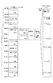
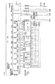
図1には、この発明の一実施例に係わるポータブルコンピュータのシステム構成が示されている。このポータブルコンピュータは、ラップトップタイプまたはノートブックタイプのコンピュータであり、メモリバス1、システムバス10、CPU11、I/Oゲートアレイ11Aを備えており、メモリバス1には主メモリ12が接続されると共に、増設メモリ13がオプション接続される。
【0014】
CPU11は、システム全体の制御を司るためのものであり、各種操作メニューを画面表示する機能や、その操作メニュー画面上でユーザによって指定された各種処理を実行する機能を有している。
【0015】
I/Oゲートアレイ11Aは、各種メモリやI/Oアクセスのための制御や、バスサイクル制御を行なう。また、このI/Oゲートアレイ11Aは、主記憶拡張のためのEMSメモリと内部メモリ拡張のための後述するROM−EMSメモリの2種類のEMSメモリ制御をサポートする。このI/Oゲートアレイ11Aから出力されるチップセレクト信号CS1,CS2,…は、漢字ROM19、辞書ROM20、DOSROM21、アプリケーションROM22、プリンタファームウェアROM23、ユーザROM24、アウトラインフォントROM25、プリンタバッファRAM26、メニューROM27から構成されるROM−EMSメモリの制御に使用される。
【0016】
主メモリ12には、処理対象となるプログラムおよびデータ等が格納される。この主メモリ12は例えば2Mバイトの記憶容量を有し、最初の1Mバイトのうちの640Kバイトがシステムメモリとして利用され、残りの384Kバイトがワークエリアとして利用される。また、この主メモリ12の2Mバイトの内で前述のシステムメモリ領域を除く一部の領域は、ハードRAMと称されるRAMディスクドライブや、EMSメモリとして利用可能である。増設メモリ13は、2Mバイト/4Mバイト/8Mバイトのメモリカードであり、メモリ拡張のために必要に応じて装着される。この増設メモリ13によって拡張されたメモリ領域にも、前述のハードRAMやEMSメモリを設定することが可能である。
【0017】
システムバス10には、DMAコントローラ(直接メモリアクセスコントローラ)14、割り込みコントローラ15、タイマ16、リアルタイムクロック17およびバックアップRAM18が接続されている。リアルタイムクロック17は、独自の動作用電池を持つ時計モジュールであり、その電池から常時電源が供給されるCMOS構成のスタティックRAMを有している。このスタティックRAMは、システム構成を示すセットアップ情報の格納等に利用される。バックアップRAM18は、バッテリバックアップされたメモリであり、32Kバイトの記憶容量を有している。このバックアップRAM18には、ユーザによって設定されるシステム環境設定情報(CONFIG,SYS)が格納される。
【0018】
システムバス10には、さらに、漢字ROM19、辞書ROM20、DOSROM21、アプリケーションROM22、プリンタファームウェアROM23、ユーザROM24、アウトラインフォントROM25、プリンタバッファRAM26、およびメニューROM27が接続されている。
【0019】
漢字ROM19は、1Mバイト(64Kバイト×16ページ)の記憶容量を有しており、ここには種々の漢字フォントが記憶されている。辞書ROM20は、512Kバイト(64Kバイト×8ページ)の記憶容量を有しており、カナー漢字変換テーブルとして利用される。DOSROM21は、512Kバイト(64Kバイト×8ページ)の記憶容量を有しており、ここにはDOS(Disk Operating System )等のオペレーティングシステムが予め記憶されている。また、このDOSROM21には、そのオペレーティングシステムの起動時に実行される自動実行バッチファイルとしてメニュー表示プログラムが記憶されている。
【0020】
アプリケーションROM22は、512Kバイト(64Kバイト×32ページ)の記憶容量を有しており、表計算プログラムが記憶されているメモリ領域とワープロ用プログラムが記憶されるメモリ領域を備えている。
【0021】
プリンタファームウェアROM23は、256Kバイト(64Kバイト×4ページ)の記憶容量を有しており、ここには内蔵プリンタ36の制御を行うファームウェア、およびアウトラインフォント等の文字フォントの展開を行うファームウェアが格納されている。ユーザROM24は、ICソケットを介してシステムバス10に接続されるものであり、ユーザによって必要に応じて装着される。このユーザROM24は、例えばOTPROMによって構成されている。
【0022】
アウトラインフォントROM25は、8Mバイト(64Kバイト×128ページ)の記憶容量を有しており、ここには、各種書体のアウトラインフォントが格納されている。また、アウトラインフォントのフォントソースは、使用する文字サイズに応じて適切なフォントが選べるように1文字種当たり複数種のフォントが用意されている。プリンタバッファRAM26は、2MバイトのSRAMのなかの32Kバイトの領域を利用して実現されており、ここには印字データが展開される。
【0023】
メニューROM27は、640Kバイト(64Kバイト×10ページ)の記憶容量を有しており、ここにはメニュー画面に表示するアイコンや、スケジュール、住所録等の個人情報を管理するPIMプログラムが格納されている。
【0024】
ここで、これら漢字ROM19、辞書ROM20、DOSROM21、アプリケーションROM22、プリンタファームウェアROM23、ユーザROM24、アウトラインフォントROM25、プリンタバッファRAM26、およびメニューROM27は、ROM−EMSの手法を利用することにより、所定のシステムアドレスにマッピングされたウインドウを通して選択的にアクセスされるように構成されている。このシステムの実際のメモリマップについては、図2を参照して後述する。なお、以下では、これらメモリをROM−EMSメモリ100と総称することにする。
【0025】
ROM−EMSメモリ100はROMディスクドライブとして機能し、このROM−EMSメモリ100内の各ファイルの格納位置は、メニューROM27の空き領域に格納されているファイル管理テーブル(FAT;Fail Alocation Table)271によって管理されている。このファイル管理テーブル271は、ROM−EMSメモリ100をディスク装置にエミュレートするために、各ファイルの格納位置やクラスタの繋がりをシリンダ番号、セクタ番号、ヘッド番号によって管理する。
【0026】
また、実際には、DOSROM21、辞書ROM20、および漢字ROM19は2Mバイトの1個のマスクROM(ROM#1)によって構成されており、アプリケーションROM22は1個のマスクROM(ROM#2)によって構成され、アウトラインフォントROM25はそれぞれ2Mバイトの3個のマスクROM(ROM#3〜#5)から構成され、プリンタファームウェアROM23、メニューROM27、およびシステムROM28は1Mバイトの1個のフラッシュEEPROM(ROM#6)から構成され、ユーザROM24は512Kバイトの1個のOTPROM(ROM#6)から構成されている。
【0027】
システムバス10には、さらに、システムROM28、FDDコントローラ29、プリンタコントローラ30、RS−232Cコントローラ31、キーボードコントローラ32、およびディスプレイコントローラ33が接続されている。
【0028】
システムROM28は、64Kバイトの記憶容量を有しており、ここにはブートストラッププログラムや各種基本入出力プログラム(BIOS;Basic I/O System)が格納されている。FDDコントローラ29は、3.5インチのフロッピーディスクを駆動するフロッピーディスクドライブ(FDD)38を制御する。フロッピーディスクドライブ(FDD)38は、720Kバイト/12Mバイト/1.44Mバイトの3種類の記録形式をサポートする3モードドライブである。また、FDDコントローラ29は、FDD/プリンタコネクタ39を介してオプション接続される例えば5インチのフロッピーディスクドライブの制御も行う。プリンタコントローラ30は、FDD/プリンタコネクタ39を介してオプション接続される外部プリンタの制御を行なう。RS−232Cコントローラ31は、RS−232C機器の制御を行なう。キーボードコントローラ32は、85キーの内蔵キーボード40やマウスの制御を行なう。ディスプレイコントローラ33は、画像メモリ(VRAM)34のリード/ライト制御、および640×400ドットの解像度を持つ白黒液晶ディスプレイ41の表示制御を行なう。
【0029】
また、このポータブルコンピュータは、内蔵プリンタコントローラ35、および内蔵プリンタ36を備えている。内蔵プリンタコントローラ35は、内蔵プリンタ36を制御するためのものであり、I/Oゲートアレイ11Aに接続されている。内蔵プリンタ36は、このポータブルコンピュータ本体に組み込まれた56ドットのシリアル熱転写プリンタである。この内蔵プリンタ36には、ハガキ用の自動給紙装置を接続することができる。
【0030】
さらに、このポータブルコンピュータは、これら各ユニットに動作電源やバックアップ用電源を供給するための電源コントローラ42を備えており、また2.5インチの本体内蔵型ハードディスクパック37がオプションで装着されるように構成されている。このハードディスクパック37には、ハードディスクドライブ(HDD)とハードディスクドライブコントローラ(HDC)が設けられている。
【0031】
次に、図2を参照して、図1のポータブルコンピュータのCPU11によって管理されるメモリマップの一例を説明する。
【0032】
図示のように、メモリアドレス“0E0000H”から“0EFFFFH”までの64Kバイトのアドレス空間には、漢字ROM19、辞書ROM20、およびROM−EMSウインドウが共通にマッピングされている。ROM−EMSウインドウは、前述のように漢字ROM19、辞書ROM20、DOSROM21、アプリケーションROM22、プリンタファームウェアROM23、ユーザROM24、アウトラインフォントROM25、プリンタバッファRAM26、メニューROM27を含むROM−EMSメモリ100をそのウインドウを通してアクセスするためのものである。また、ROM−EMSメモリ100に含まれる漢字ROM19および辞書ROM20については、ROM−EMSウインドウを介してアクセスすることもできるし、そのウインドウを使用せずに直接的にアクセスすることもできる。ROM−EMSウインドウを使用しない場合には、漢字ROM19と辞書ROM20はバンク切り替え等の手法によって択一的にアクセスされる。また、これら漢字ROM19および辞書ROM20のアクセスにおいて、バンク切り替え方式を利用するかROM−EMSウインドウを利用するかについては排他制御が行われ、バンク切り替えとROM−EMSウインドウのいずれか一方だけが有効になる。
【0033】
また、メモリアドレス“0D0000H”から“0DFFFFH”までの64Kバイトのアドレス空間には、主記憶拡張のための通常のEMSウインドウが割り当てられている。このEMSウインドウは、LIM−EMSと称される仕様にしたがって例えば増設メモリ13をEMSメモリとして使用するためのものである。
【0034】
このように、この実施例のポータブルコンピュータは、主記憶拡張のためのEMSメモリとROM等の内部メモリ拡張のためのROM−EMSメモリとの2種類のEMSメモリをサポートしている。また、ROM−EMSメモリ100から構成されるROMディスクドライブとハードRAM(HRAM)との2台の半導体ディスクドライブを持つ。
【0035】
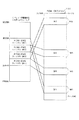
図3には、ROM−EMSウインドウを利用したROM−EMSメモリ100のアクセスの原理が示されている。
【0036】
すなわち、メモリアドレス“0E0000H”から“0F0000H”までの64Kバイトの領域は、図示のように、16Kバイト×4ページのROM−EMSウインドウ(W1〜W4)に分割されており、これらウインドウ(W1〜W4)はそれぞれ独立にROM−EMSメモリ100に割り当てられた拡張メモリアドレス空間にマッピングされる。ウインドウ(W1〜W4)がROM−EMSメモリ100の拡張メモリアドレス空間のどのアドレスにマッピングされるかは、ROM−EMSウインドウ(W1〜W4)それぞれに対応したページアドレスによって決定される。
【0037】
ページアドレスは11ビット幅を有しており、このページアドレスの値を書き替えることによって、最大で32Mバイト(=16Kバイト×2048ページ)の拡張メモリアドレス空間をROM−EMSメモリ100のアクセスに利用することができる。この32Mバイトのアドレス空間は、CPU11によって直接管理されるシステムアドレスとは独立したROM−EMS専用の拡張メモリアドレス空間であり、ROM−EMSメモリ100に含まれる各種メモリは、その32Mバイトの拡張メモリアドレス空間の任意の位置にマッピングすることができる。
【0038】
このようなROM−EMSメモリ100のアクセス制御は、I/Oゲートアレイ11Aに設けられたROM−EMS制御用の専用レジスタ群を利用して行われる。
【0039】
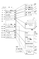
次に、図4を参照して、これらROM−EMS制御レジスタ群を利用したROM−EMS制御の原理を説明する。
【0040】
図4に示されているように、I/Oゲートアレイ11AのROM−EMS制御レジスタ群には、ROM−EMSコントロールレジスタ201、ROM−EMSインデックスレジスタ202、ROM−EMSデータレジスタ(ページレジスタ)203a〜203dが含まれている。
【0041】
ROM−EMSコントロールレジスタ201には、ゼネラルイネーブルビット(GEN)、およびバリッドビット(V)がセットされる。ゼネラルイネーブルビット(GEN)は、ROM−EMS機能全体のイネーブル/ディセーブル制御を行うためのものであり、ゼネラルイネーブルビット(GEN)=“1”はROM−EMS機能を使用するモード(ROM−EMSモード)を示し、ゼネラルイネーブルビット(GEN)=“0”はROM−EMS機能を使用しないモード (メモリアクセスモード)を示す。バリッドビット(V)は4個のROM−EMSウインドウのいずれが有効か否かを示すものであり、バリッドビット(V)=“1”は有効なウインドウがあることを示し、バリッドビット(V)=“0”は有効なウインドウが無いことを示す。
【0042】
ROM−EMSインデックスレジスタ202には、ページレジスタ203a〜203dを選択的に指定するための2ビットのセレクト情報がセットされる。このセレクト情報によって指定されたページレジスタには、任意のページアドレスを書き込むことができる。
【0043】
ページレジスタ203a〜203dは4個のROM−EMSウインドウW1〜W4にそれぞれ対応して設けられており、その各々には、イネーブルビット(E)、バリッドビット(V)、およびページアドレスがセットされる。イネーブルビット(E)は、対応するROM−EMSウインドウのイネーブル/ディセーブル制御を行うためのものであり、イネーブルビット(E)=“1”はROM−EMSウインドウが有効であることを示し、イネーブルビット(E)=“0”はROM−EMSウインドウが有効で無いことを示す。バリッドビット(V)は、対応するページレジスタのページアドレスの有効/無効の判定ビットであり、“1”は有効、“0”は無効を示す。ページアドレスは、対応するROM−EMSウインドウをROM−EMSメモリ100の32Mバイトのアドレス空間の任意のページにマッピングするためのものであり、11ビット幅(A24−A14)を有している。
【0044】
ゼネラルイネーブルビット(GEN)=“1”、且つページレジスタ203a〜203dの各ネーブルビット(E)=“1”の場合においては、例えば、ROM−EMSウインドウW1に対応するアドレス“E0000H”〜“E3FFFH”の範囲に属すシステムアドレスがCPU11から発行された時には、ROM−EMSウインドウW1に対応するページレジスタ203aが参照され、そのシステムアドレスの上位11ビットはページレジスタ203aのページアドレスに置き換えられる。そして、その11ビットのページアドレスとシステムアドレスの下位14ビットアドレスから構成される25ビット幅のROM−EMSアドレスが生成される。
【0045】
25ビットのROM−EMSアドレスは、システムバス10上に出力される。そして、そのROM−EMSアドレスの上位11ビットのページアドレスによってROM−EMSメモリ100の2048ページのうちの1ページ(16Kバイト)が指定され、その1ページ内の1バイトがROM−EMSアドレスの下位14ビットによって指定される。
【0046】
図5には、ROM−EMSメモリ100のメモリ群に対するページ割り当ての一例が示されている。
【0047】
DOSROM21、辞書ROM20、および漢字ROM19は2Mバイトの1個のマスクROM(ROM#1)によって構成されており、アプリケーションROM22は1個のマスクROM(ROM#2)によって構成され、アウトラインフォントROM25はそれぞれ2Mバイトの4個のマスクROM(ROM#3〜#6)から構成され、プリンタファームウェアROM23、メニューROM27、およびシステムROM28は1Mバイトの1個のフラッシュEEPROM(ROM#7)から構成され、ユーザROM24は512Kバイトの1個のOTPROM(ROM#8)から構成され、プリンタバッファRAM26は、それそれ1Mバイトの2個のSRAM(SRAM#1,#2)のうちの任意の32Kバイト、たとえばSRAM#1の最初の32Kバイトから構成されている。
【0048】
この場合、ROM#1にはページ0〜127までの128ぺージが割れ当てられており、そのうちのページ0〜ページ31がDOSROM21、ページ32〜ページ63が辞書ROM20、ページ64〜ページ127が漢字ROM19に割り当てられている。ROM#2にはページ128からページ255までの128ページが割り当てられており、そのうちのページ128〜ページ191が表計算プログラム領域、ページ192〜ページ255がワープロプログラム領域に割り当てられている。
【0049】
アウトラインフォントROM25を構成するROM#3〜#6には、ページ256〜ページ767までの512ページが割り当てられている。ROM#7にはページ1792〜ページ1855までの56ページが割り当てられており、そのうちのページ1792〜1808がプリンタファームウェアROM23、ページ1809〜1855がメニューROM27に割り当てられている。また、このメニューROM27の一部には、前述したFAT271が格納されている。ROM#8には、ユーザアプリケーションエリアとして定義されたページ1280〜1535の256ぺージのうちの最初の32ページが割り当てられる。SRAM#1には、SRAMエリアとして定義されたページ1920〜2047の128ぺージのうちの64ページが割り当てられ、SRAM#2には、残りの64ページが割り当てられる。SRAM#1の最初の2ページはプリンタバッファとして使用される。
【0050】
このような2048ページのページ割り当てによって、ROM−EMSメモリ100を構成する全てのメモリを、32Mバイト(2048ページ×16Kバイト)のアドレス空間内に任意にマッピングすることができる。これは、換言すれば、ROM−EMSウンイドを介してCPU11が参照することができる各種メモリのアドレス空間を最大で32Mバイトにまで拡張することができることを意味する。
【0051】
次に、図6を参照して、ROM−EMSメモリ100周辺の具体的な回路構成の一例を説明する。
【0052】
前述したように、ROM−EMSメモリ100に対する32Mバイトのアドレス空間は、CPU11によって管理されるアドレス空間とは独立したROM−EMS専用のアドレス空間である。したがって、実際の回路上は、システムアドレスとは別に、25ビット幅のROM−EMSアドレス専用のアドレスバスを用意することが必要となる。しかしながら、システムバス10の他に、ROM−EMSアドレス専用のアドレスバスをポータブルコンピュータのマザーボード上に配設すると、それによって大きな実装面積が占有されてしまう。これは、小型化が要求されるポータブルコンピュータにおいては好ましくない。
【0053】
そこで、この図6の回路構成においては、ROM−EMSメモリ100がアクセスされる時にはシステムバス10上の他のメモリに対するアクセスは発生しないことに着眼し、システムバス10内のメモリリード信号(MEMR)線101a、メモリライト信号(MEMW)線101bとは別個に、ROM−EMSメモリ100専用のメモリリード信号(ROM−EMS MEMR)線301a、メモリライト信号(ROM−EMS MEMW)線301bを設け、それらリード/ライト信号を排他制御することによって、システムバス10内のアドレスバスをROM−EMSメモリ100のアクセスとROM−EMSメモリ100以外のメモリのアクセスに共用できるように構成している。
【0054】
以下、具体的な回路構成について詳述する。
【0055】
ROM−EMSメモリ100を構成する10個のメモリチップ(ROM#1〜ROM#8、SRAM#1,SRAM#2)には、それぞれ対応するチップセレクト信号線401〜409を介してI/Oゲートアレイ11Aからのチップセレクト信号CS1〜CS9が供給される。チップセレクト信号CS1〜CS9とメモリチップとの対応関係は、次の通りである。
【0056】
CS1;ROM#1
CS2;ROM#2
CS3;ROM#3,ROM#4,ROM#5,ROM#6
CS4;予備
CS5;ROM#7
CS6;ROM#8
CS7;予備
CS8;SRAM#1
CS9;SRAM#2
これらチップセレクト信号CS1〜CS9は、ページアドレスの値に応じて選択的に付勢される。例えば、ページアドレスの値が、ROM#1に割り付けられているページ0〜127の範囲に属す場合には、チップセレクト信号CS1が付勢される。
【0057】
また、メモリチップ(ROM#1〜ROM#8、SRAM#1,SRAM#2)には、メモリリード信号線301aを介してI/Oゲートアレイ11AからのROM−EMSメモリ専用のメモリリード信号(ROM−EMS MEMR)が共通に供給される。このメモリリード信号(ROM−EMS MEMR)は、ROM−EMSメモリ100をリードアクセスする時に付勢される。さらに、ライト可能なメモリチップ、すなわち、フラッシュEEPROMから構成されるROM#7、OTPROMから構成されるROM#8、およびSRAM#1,#2については、メモリライト信号線302aを介してI/Oゲートアレイ11AからのROM−EMSメモリ専用のメモリライト信号(ROM−EMS MEMW)が共通に供給される。このメモリライト信号(ROM−EMS MEMW)は、ROM#7、ROM#8、またはSRAM#1,#2にデータを書き込む時に付勢される。
【0058】
さらに、これらメモリチップ(ROM#1〜ROM#8、SRAM#1,SRAM#2)の各々は、システムバス10の下位アドレスバス(SA19−0)102,上位アドレスバス(LA23−17)103、データバス(SD15−0)104に接続されている。この場合、各メモリチップに接続されるデータバス幅は8ビットであるので、その8ビットデータとしては、16ビット幅のデータバス(SD15−0)104上の下位8ビット(SD7−0)が使用される。
【0059】
また、ROM−EMSアドレスは、11ビットのページアドレス(A24−14)と14ビットのページ内アドレス(A13−0)とから構成される25ビット幅であるが、各メモリチップへのアドレスとしては、その25ビットのROM−EMSアドレスの内で必要なビット数だけが下位側から順に使用される。
【0060】
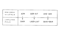
14ビットのページ内アドレス(A13−0)としては、下位アドレスバス (SA19−0)102上の下位14ビット(SA13−0)がそのまま使用される。また、11ビットのページアドレス(A24−14)としては、下位アドレスバス(SA19−0)102上の4ビット(SA19,SA16−14)と、上位アドレスバス(LA23−17)103上の上位7ビット(LA23−17)が使用される。
【0061】
前述したように、11ビットのページアドレス(A24−14)の値は、CPU11からの24ビットのシステムアドレスによって指定されるROM−EMSウインドウに対応するページレジスタの値である。このため、ROM−EMSメモリ100がアクセスされる時には、24ビットのシステムアドレスの上位11ビットが、ページレジスタの値によって規定される11ビットのページアドレス(A24−A14)に変換され、そのページアドレス(A24−A14)が下位アドレスバス(SA19−0)102上の4ビット(SA19,SA16−14)と上位アドレスバス(LA23−17)103上の上位7ビット(LA23−17)に出力されることになる。この場合、ROM−EMSメモリ100のページアドレス(A24−A14)とシステムバス10上のアドレスとの対応関係は図7に示す通りである。一方、CPU11からの24ビットのシステムアドレスの下位14ビットは、そのまま下位アドレスバス(SA19−0)102の下位14ビットに出力される。
【0062】
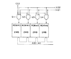
なお、ROM#3〜#6については1つのチップセレクト信号CS3だけが利用されているが、実際には、図8に示されているように、チップセレクト信号CS3に加え、ROM−EMSアドレスの所定の2ビットがメモリチップの切り替えに使用されている。この図8の例では、4個のANDゲートG1〜G4を利用して、2ビットのアドレス“A23,A22”が“1,1”の時にROM#6、“1,0”の時にROM#5、“0,1”の時にROM#4、“0,0”の時にROM#3が選択されるように構成されている。
【0063】
また、チップセレクト信号に余りがあれば、ROM#3〜#6にそれぞれ別個のチップセレクト信号を供給しても良いことはもちろんである。
【0064】
次に、図6の構成におけるROM−EMSメモリ100のアクセ動作を説明する。
【0065】
すなわち、ROM−EMSメモリ100をアクセスする時には、まず、I/Oゲートアレイ11Aは、システムバス10内のメモリリード信号(MEMR)線101aおよびメモリライト信号(MEMW)線101bの付勢を共に禁止し、代わりに、ROM−EMS専用のメモリリード信号(ROM−EMS MEMR)線301a、またはメモリライト信号(ROM−EMS MEMW)線301bを付勢する。メモリリード信号(ROM−EMS MEMR)線301aとメモリライト信号(ROM−EMS MEMW)線301bのどちらが付勢されるかは、CPU11からのメモリアクセス要求がリード要求かライト要求かによって決定される。
【0066】
ついで、I/Oゲートアレイ11Aは、CPU11から出力される24ビットのシステムアドレスの上位11ビットを、システムアドレスによって指定されるROM−EMSウインドウに対応するページレジスタを用いて、11ビットのページアドレス(A24−14)に変換する。I/Oゲートアレイ11Aは、そのページアドレス(A24−14)が属すページ範囲に応じて、チップセレクト信号CS1〜CS8の1つを付勢する。そして、I/Oゲートアレイ11Aは、ページアドレス(A24−14)を下位アドレスバス(SA19−0)102上の4ビット(SA19,SA16−14)と上位アドレスバス(LA23−17)103上の上位7ビット(LA23−17)にそれぞれ対応して出力すると共に、CPU11からの24ビットのシステムアドレスの下位14ビットをページ内アドレス(A13−0)として下位アドレスバス(SA19−0)102の下位14ビットに出力する。
【0067】
付勢されたチップセレクト信号を受信したメモリチップはイネーブル状態に設定され、25ビットのROM−EMSアドレス(A24−0)によってアクセスされる。
【0068】
一方、ROM−EMSメモリ100以外のシステムバス10上のメモリをアクセスする場合には、通常通り、メモリリード信号(MEMR)線101aまたはメモリライト信号(MEMR)線101bが付勢され、CPU11からのメモリアドレスがアドレスバス102,103に出力される。これにより、ROM−EMSメモリ100以外のメモリアクセスが可能となる。
【0069】
以上のように、図6の構成においては、システムバス10内のアドレスバスをROM−EMSメモリ100のアクセスとシステムバス10上の他のメモリのアクセスに共用することができる。したがって、ROM−EMSメモリ100専用の25ビット幅のアドレスバスをマザーボード上に配設することなく、32Mバイトのアドレス空間をROM−EMSメモリ100に割り当てることができる。
【0070】
なお、ROM−EMSメモリ100以外のメモリだけでなく、ROM#1に組み込まれている漢字ROM20、辞書ROM19についても、ROM−EMSウインドウを利用しない通常のメモリアクセスが可能である。これは、ROM−EMSモードで無い場合(図4のコントロールレジスタ201のゼネラルイネーブルビットGEN=“0”)においても、CPU11からのメモリアドレスの値がアドレス“0E0000H”から“0EFFFFH”までの範囲に属す時に、ROM#1に対応するチップセレクト信号CS1が付勢されるように構成することによって実現できる。また、この場合、漢字ROM20と辞書ROM19は64Kバイの同一アドレス空間にマッピングされているので、それら漢字ROM20と辞書ROM19のアクセスは、メモリバンク切り替えの手法によって択一的に許可される。
【0071】
このメモリバンク切り替えは周知の技術であるのでここでは詳述しないが、例えば、I/Oゲートアレイ11Aの所定のI/Oレジスタにメモリ選択のためのデータを書き込み、そのデータをROM#1のアドレスに接続すること等によって実現することができる。この場合、漢字ROM20と辞書ROM19のどちらがアクセスされるかは、書き込みデータの内容に応じて決定される。
【0072】
次に、図9を参照して、I/Oゲートアレイ11Aに設けられているROM−EMS制御のためのハードウェア構成を説明する。
【0073】
図示のように、I/Oゲートアレイ11Aには、前述したROM−EMS制御レンジスタ群に加え、第1および第2のアドレス範囲判定回路501,502、チップセレクト信号(CS)発生回路503、アドレス変換回路504、およびリード/ライト信号出力回路505を備えている。
【0074】
第1のアドレス範囲判定回路501は、ROM−EMSモード(コントロールレジスタ201のゼネラルイネーブルビットGEN=“1”)の時に動作されるものであり、CPU11からの24ビットのシステムアドレスの値が属すアドレス範囲がROM−EMSウインドウW1〜W4のどのウインドウに対応するかを検出し、検出したウインドウに対応したウインドウ検出信号w1〜w4の1つを“1”レベルに付勢する。これらウインドウ検出信号w1〜w4は、チップセレクト信号(CS)発生回路503、およびアドレス変換回路504にそれぞれ供給される。
【0075】
第2のアドレス範囲判定回路502は、通常のメモリアクセスモード(コントロールレジスタ201のゼネラルイネーブルビットGEN=“0”)の時に動作されるものであり、CPU11からの24ビットのシステムアドレスの値がアドレス“0E0000H”〜“0EFFFFH”の範囲に属すか否かを検出し、属す時に検出信号Sを“1”レベルに付勢する。この“1”レベルの検出信号Sは、漢字ROM20または辞書ROM19を通常のメモリアクセスモードでアクセスする時のチップセレクト信号CS1として使用されるものであり、ORゲート506の第1入力に供給される。
【0076】
チップセレクト信号(CS)発生回路503は、4つのページレジスタ203a〜203dの1つを選択し、その選択したページレジスタにセットされている11ビットのページアドレスの値に応じて、ORゲート506の第2入力への信号およびチップセレクト信号CS2〜CS9を選択的に“1”レベルに付勢する。どのページレジスタを選択するかは、ウインドウ検出信号w1〜w4によって決定される。すなわち、ウインドウ検出信号w1が付勢された時にはROM−EMSウインドウW1に対応するページレジスタ203aが選択され、同様に、ウインドウ検出信号w2が付勢された時にはROM−EMSウインドウW2に対応するページレジスタ203b、ウインドウ検出信号w3が付勢された時にはROM−EMSウインドウW3に対応するページレジスタ203c、ウインドウ検出信号w4が付勢された時にはROM−EMSウインドウW4に対応するページレジスタ203dが選択される。
【0077】
このチップセレクト信号(CS)発生回路503においては、11ビットのページアドレスの値によって指定されるページ番号がROM#1に対応するページ範囲に属す時にはORゲート506の第2入力への信号が“1”レベルに付勢される。同様に、そのページ番号がROM#2に対応するページ範囲に属す時にはチップセレクト信号CS2、ROM#3〜#6に対応するページ範囲に属す時にはチップセレクト信号CS3、第1の予備ROMに対応するページ範囲に属す時にはチップセレクト信号CS4、ROM#7に対応するページ範囲に属す時にはチップセレクト信号CS5、ROM#8に対応するページ範囲に属す時にはチップセレクト信号CS6、第2の予備ROMに対応するページ範囲に属す時にはチップセレクト信号CS7、SRAM#1に対応するページ範囲に属す時にはチップセレクト信号CS8、SRAM#2に対応するページ範囲に属す時にはチップセレクト信号CS9が“1”レベルに付勢される。
【0078】
アドレス変換回路504は、4つのページレジスタ203a〜203dの1つを選択し、CPU11からの24ビットのシステムアドレスを、選択したページレジスタにセットされている11ビットのページアドレスを用いて24ビットのROM−EMSアドレスに変換してアドレスバス102,103に出力する。どのページレジスタを選択するかは、ウインドウ検出信号w1〜w4によって決定される。すなわち、ウインドウ検出信号w1が付勢された時にはROM−EMSウインドウW1に対応するページレジスタ203aが選択され、同様に、ウインドウ検出信号w1が付勢された時にはROM−EMSウインドウW2に対応するページレジスタ203b、ウインドウ検出信号w3が付勢された時にはROM−EMSウインドウW3に対応するページレジスタ203c、ウインドウ検出信号w4が付勢された時にはROM−EMSウインドウW4に対応するページレジスタ203dが選択される。
【0079】
システムアドレスからROM−EMSアドレスへの変換においては、24ビットのシステムアドレスの上位11ビットが11ビットのページアドレス(A24−14)に置き換えられる。そして、この11ビットのページアドレス(A24−14)の下位側に、24ビットのメモリアドレスの下位14ビットが加えられて、25ビットのROM−EMSアドレス(A24−0)が得られる。
【0080】
一方、ウインドウ検出信号w1〜w4のいずれも付勢されない時には、アドレス変換回路504は変換動作を実行せず、24ビットのメモリアドレスをそのままアドレスバス102,103に出力する。
【0081】
リード/ライト信号出力回路505は、CPU11からのメモリリード要求に応じてROM−EMSメモリリード信号(ROM−EMS MEMR)およびメモリリード信号(MEMR)を択一的に発生する。ROM−EMSメモリリード信号(ROM−EMS MEMR)とメモリリード信号(MEMR)のどちらをを発生するかは、ゼネラルイネーブルビットGENによって制御される。すなわち、ROM−EMSモード(コントロールレジスタ201のゼネラルイネーブルビットGEN=“1”)の時にCPU11からのメモリリード要求が入力されるとROM−EMSメモリリード信号(ROM−EMS MEMR)が発生され、通常のメモリアクセスモード(ゼネラルイネーブルビットGEN=“0”)の時にCPU11からのメモリリード要求が入力されるとメモリリード信号(MEMR)が発生される。
【0082】
また、リード/ライト信号出力回路505は、CPU11からのメモリライト要求に応じてROM−EMSメモリライト信号(ROM−EMS MEMW)およびメモリライト信号(MEMW)を択一的に発生する。すなわち、ROM−EMSモードの時にCPU11からのメモリライト要求が入力されるとROM−EMSメモリライト信号(ROM−EMS MEMW)が発生され、通常のメモリアクセスモードの時にCPU11からのメモリライト要求が入力されるとメモリライト信号(MEMW)が発生される。
【0083】
なお、図9ではROM−EMSメモリ制御のためのハードウェア構成だけを示したが、実際には、主記憶拡張のための通常のEMSメモリ制御をサポートするためのハードウェアもI/Oゲートアレイ11Aに含まれている。このハードウェアは、ROM−EMS制御レジスタ群と同様のレジスタ群を備えている。
【0084】
次に、図10のフローチャートを参照して、ROM−EMSメモリ100をアクセスする際に実行される全体の処理手順を説明する。
【0085】
ROM−EMSメモリ100はROMディスクドライブであるので、オペレーティングシステム(DOS)は、まず、FAT271を参照して、ROM−EMSメモリ100内に格納されているリード/ライト対象の目的ファイルに対応するシリンダ、ヘッド、セクタ番号を認識する(ステップS11)。このオペレーティングシステム(DOS)は、DOSROM21のオペレーティングシステムと、フロッピーディスク等からインストールしたオペレーティングシステムのどちらであっても良い。
【0086】
そして、そのオペレーティングシステムは、システムROM28に格納されているディスクドライバ用BIOS(INT13H)を装置番号81Hで起動し、そのBIOSにシリンダ、ヘッド、セクタ番号をパラメタとして与える(ステップS12)。ここで、装置番号81Hは、ROM−EMSメモリ100からなるROMディスクドライブを示している。この装置番号81Hにより、BIOSのDOS−ROMドライバが実行される。
【0087】
BIOSのDOSROMドライバは、まず、ROM−EMSモードを有効にするためにコントロールレジスタ201のゼネラルイネーブルビットGENを“1”にセットし、ついで、シリンダ、ヘッド、セクタ番号をROM−EMSメモリ100のページアドレス(A24−14)に変換する(ステップS13)。この変換動作はROMディスクドライバ内に定義された変換情報に従って実行される。ついで、DOSROMドライバは、ページアドレス(A24−14)を例えばページレジスタ203aにセットする(ステップS14)。
【0088】
I/Oゲートアレイ11Aは、ページレジスタ203aにセットされたページアドレスの値に応じてチップセレクト信号CS1〜CS9の1つを付勢し(ステップS15)、ROM−EMSメモリリード信号(ROM−EMS MEMR)またはROM−EMSメモリライト信号(ROM−EMS MEMW)を発生する(ステップS16)。
【0089】
この後、I/Oゲートアレイ11Aは、ページレジスタ203aにセットされたページアドレスの値にしたがって、その時のCPU11からのシステムアドレスを、そのシステムアドレスとは独立したROM−EMSアドレスに変換してシステムバス10に出力する(ステップS17)。そして、そのROM−EMSアドレスにしたがってROM−EMSメモリ100のリード/ライトアクセスが実行される(ステップS18)。
【0090】
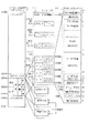
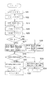
次に、図11のフローチャートを参照して、このポータブルコンピュータの電源投入時の動作を説明する。
【0091】
すなわち、CPU11は、まず、ポータブルコンピユータ内の各種周辺LSI等のハードウェアやメモリの信頼性テスト、およびそれらの初期化を行なう(ステップS21,S22)。この初期化処理においては、リアルタイムクロック17に保持されているシステム構成情報にしたがった初期設定がなされる。次いで、CPU11は、DOSROM21のチェックサムのチェックを行なうと共に(ステップS23)、フロッピーディスクドライブ38およびハードディスクパック37の装着チェックと初期化を行なう(ステップS24〜S26)。この初期化処理では、リアルタイムクロック17に保持されているシステム構成情報にしたがってハードディスクパック37およびフロッピーディスクドライブ38の初期設定がなされる。
【0092】
ハードディスクパック37が装着されてない場合には、BIOSのディスクドライバ(INT13H)を起動する固定ディスク用の装置番号80HがハードRAM制御のためのハードRAMドライバ、装置番号81HがDOSROMドライバに割り当てられる(ステップS28)。これにより、ハードRAMがCドライブ、DOSROM21を含むROM−EMSメモリ100がDドライブとなる。
【0093】
一方、ハードディスクパック37が装着されている場合には、装置番号80Hがハードディスクパック37を制御するためのHDDドライバ、装置番号81HがDOSROMドライバに割り当てられると共に、新たに用意された装置番号82HがハードRAMドライバに割り当てられる(ステップS27)。この場合、DOS等のオペレーティンクシステムが指定する固定ディスク用の装置番号は80Hと81Hの2つであるので、新たに用意された装置番号82Hの指定は、オペレーティンクシステムではなく、ハードRAMのファイル参照のために用意された専用のユーティリティプログラム等によって行われる。また、この時には、ハードディスクパック37がCドライブ、DOSROM21を含むROM−EMSメモリ100がDドライブとなる。
【0094】
このような初期設定が完了すると、今度は、オペレーティングシステム(DOS)を読み込む動作が実行される。すなわち、CPU11は、まず、リアルタイムクロック17に保持されているシステム構成情報を読み込み、“DOSの起動=DOSROM”に設定されているか否かを判別する(ステップS29)。“DOSの起動=DOSROM”に設定されている場合には、CPU11は、DOSROM21からオペレーティングシステムを読み込むために、システムROM28に記憶されているディスクドライバ用BIOS(INT13H)を装置番号81Hで実行する(ステップS30)。この装置番号81Hにはハードディスクパック37の装着の有無に係わらず、DOSROMドライバが割り当てられている。したがって、この時にはDOSROMドライバが実行される。
【0095】
DOSROMドライバは、まず、ROM−EMSモードを有効にするためにコントロールレジスタ201のゼネラルイネーブルビットGENを“1”にセットし、ついで、DOSROM21内のIPLの格納位置に対応するあらかじめ定められたシリンダ、ヘッド、セクタ番号(例えば、シリンダ番号=0、ヘッド番号=0、セクタ番号=1)をROM−EMSメモリ100のページアドレス(A24−14)に変換する。ついで、DOSROMドライバは、ページアドレス(A24−14)を例えばページレジスタ203aにセットする。以降、I/Oゲートアレイ11Aの制御の下にDOSROM21がROM−EMSウンドW1を通してリードアクセスされ、その所定位置に書き込まれているIPLが主メモリ12のシステムメモリ領域に読み込まれる。
【0096】
そして、CPU11は、そのIPLを実行してDOSROM21から主メモリ12のシステムメモリ領域に、DOSのシステムファイルを読み込み、そのオペレーティングシステムを起動する(ステップS31)。DOSROM21には、前述したようにメニュー表示プログラムが自動実行バッチファイルとして記憶されているので、このオペレーティングシステムの起動時には最初にその自動実行バッチファイルがDOSROM21から読み込まれて、所定のメニュ−画面が表示される(ステップS32)。
【0097】
一方、システム構成情報が“DOSの起動=FDD/HDD”に設定されている場合には、CPU11は、システムROM28に記憶されているディスクドライバ用BIOS(INT13H)を装置番号00H、01H、80H、81Hの順で起動する(ステップS28)。ここで、装置番号00Hはフロッピーディスクドライブ38に対応するBIOSドライバを示し、装置番号01Hは外付けフロッピーディスクドライブに対応するBIOSドライバを示し、装置番号80Hはハードディスクパック37装着時にはHDDドライバを示し、未装着時にはハードRAMドライバを示す。また、装置番号81HはDOSROMドライバを示す。この結果、フロッピーディスクドライブ、ハードディスク/ハードRAM、DOSROMの順でオペレーティングシステム(DOS)が探され、ブート処理が実行される(ステップS33)。この場合、フロッピーディスクドライブ、ハードディスクパック/ハードRAMにオペレーティングシステムがあると通常通りそのオペレーティングシステムが起動され、これらにオペレーティングシステムがない場合には、DOSROM21のオペレーティングシステムが起動されて自動的にメニュー画面が表示される。
【0098】
このように、この実施例では、ハードディスクパック37が装着されると、ハードRAMドライバに割り当てられている装置番号が80Hから82Hに変更される。このため、ハードディスクパック37の装着状態においては、ハードRAMドライバの実行を装置番号82Hによって指定することができる。したがって、ハードRAMとDOSROM21の2台の固定ディスクを使用している状態でハードディスクパック37を装着しても、専用のユーティリティ等によって装置番号82Hを指定すれば、ハードRAMに蓄えたデータを参照することが可能になる。
【0099】
尚、図11の立ち上げ処理では、DOSROM21のオペレーティングシステムの起動時にはメニュー表示プログラムが最初に必ず実行されたが、システム起動時に実行されるファイルをユーザが任意に設定することもできる。
【0100】
以下、その自動実行ファイルの登録処理、およびシステム立ち上げ時の動作について説明する。自動実行ファイルの登録処理は、例えば、DOSROM21のオペレーティングシステムによって提供される操作メニュー画面上で自動実行ファイル名を登録するためのユーティリティを起動することによって実行開始されるものである。
【0101】
まず、図12を参照して、操作メニュー画面の一例を説明する。
【0102】
図12に於いて、a1乃至a12はそれぞれ作業選択のためのメニュアイコンである。これらアイコンのうち、a1はアプリケーションROM22に記憶されたワープロ用アプリケーションプログラムの実行を指示するためのワープロアイコン、a2はアプリケーションROM22に記憶された表計算用アプリケーションプログラムの実行を指示するための表計算アイコン、a3はカレンダ、電卓、世界時計等のアクセサリ機能の実行を指示するためのアクセサリアイコンである。a4,a5は市販ソフトウェア等の任意ソフトウェアのメニュ登録またはそのメニュ登録したソフトウェアの実行を指示するためのユーザ登録アイコンである。a6は市販ソフトウェア等の任意のソフトウェアをこのポータブルコンピュータ本体のハードRAMまたはハードディスクパック37にインストールするためのソフトインストールアイコンである。a7はフロッピーディスクで供給される市販ソフトウェアの実行(FDのautoexec.batを実行する)を指示するためのFD実行アイコンである。a8はフロッピーディスクのすべての内容を新たなフロッピーディスクに複写(diskcopyコマンドを実行する)することを指示するための予備FD作成アイコンである。a9はフロッピーディスクを初期化する(formatコマンドを実行する)FD初期化アイコンである。a10はハードRAM又はハードディスクパック37に格納されたすべての内容をフロッピーディスクへコピーすることを指示するための本体→FDアイコンである。この場合、ハードRAMの場合はallcopy コマンドが実行され、ハードディスクの場合はbackupコマンドが実行される。a11はフロッピーディスクのすべての内容を本体へコピー(ハードRAMの場合はallcopy コマンドの実行、ハードディスクの場合はbackupコマンドの実行)することを指示するためのFD→本体アイコンである。a12はDOSーROM21に格納されたオペレーティングシステイム(DOS)を使用可能にする(command.com を起動する)MSーDOSアイコンである。
【0103】
b1乃至b12は上記各アイコンa1〜a122 に対応して表示されるアイコンタイトルである。
【0104】
c1はメッセージ行(タイトルバー)であり、ここには、選択状態にあるアイコン、即ち反転表示等により強調表示されたアイコンの作業内容等が表示される。図においては、ワープロアイコンa1が選択されているので、ワープロアイコンa1、アイコンタイトルb1がそれぞれ反転表示され、メッセージ行c1には“ワープロをはじめます”のメッセージが表示される。この状態で、[Enter]キーが入力されと、ワープロ用アプリケーションプログラムが主メモリ12に読み込まれて実行される。ワープロ用アプリケーションプログラムが実行されると、操作メニュー画面からそのワープロ用アプリケーションプログラムによって提供される文字入力画面に画面が切り替えられる。
【0105】
また、図において、DOSアイコンa12が選択されると、この時には既にDOSROM21のオペーレーティングシステム(DOS)は起動されいるので、直ぐにコマンドの受付け可能状態となり、画面上にはDOSROM21のプロンプト(プロンプトCまたはD)が画面表示される。
【0106】
さらに、図11において、d1乃至d10はそれぞれキーボード33上に設けられるファンクションキーF1〜F10の機能表示部である。すなわち、d1はリアルタイムクロック17のメモリに日付と時刻の設定を行なうファンクションキーF1の機能表示部、d2は漢字入力モードと入力練習のする/しないを選択するファンクションキーF2の機能表示部、d3はリジューム、スピーカ、ローバッテリアラーム、オートパワーオフ、画面反転表示、ハードディスク自動停止等、各種システム構成情報をリアルタイムクロック17のメモリに設定するファンクションキーF3の機能表示部、d4はプリンタドライバの種類を選択するファンクションキーF4の機能表示部、d5はハードRAM、EMS等のメモリの設定を行なうファンクションキーF5の機能表示部、d7は利用者のコマンドをユーザ登録1/ユーザ登録2の各メニュに登録するファンクションキーF7の機能表示部、d8はシステム起動時に自動実行すべきファイル名を登録するファンクションF8の機能表示部、d9はシステム環境設定ファイル(CONFIG.SYS)の選択を行なうファンクションキーF9の機能表示部、d10はハードディスクパック37が実装されたときのみ、有効表示となって、ハードディスクのパーティションを定義し、フォーマットを行なう、ファンクションキーF10の機能表示部である。
【0107】
次に、図13を参照して、自動実行ファイル名の登録処理について説明する。
【0108】
前述したように、DOSROM21のオペレーティングシステムがブートされると、図12で説明したメニュ−画面が表示される(ステップS41)。このメニュ−画面上にて自動実行ファイル名登録のためのファンクションキーF8が押下されると、メニュ−表示プログラム中の自動実行ファイル登録ユーティリティがCPU11によって実行される(ステップS42)。CPU11は、ファイル名の入力用ウインドウを表示し、登録ファイル名の入力を受け付ける(ステップS43)。この後、CPU11は、キーボード40から入力された自動実行ファイル名をリアルタイムクロック17のスタティックRAM(CMOSメモリ)にセーブする(ステップS44)。これにより、自動実行ファイル名が登録される。
【0109】
次に、図14のフローチャートを参照して、システム起動時のファイルの自動実行処理について説明する。
【0110】
前述したように、BIOS(INT13H)を装置番号81Hで起動すると、DOSROM21のオペレーティングシステムがブートされる(ステップS51)。この後、CPU11は、リアルタイムクロック17のCMOSメモリを参照してそこに自動実行ファイル名が登録されているか否かを調べる(ステップS52)。自動実行ファイル名が登録されている場合には、その自動実行ファイル名によって指定されるプログラム、例えばアプリケーションROM22のワープログラム等が自動実行される(ステップS53)。一方、自動実行ファイル名がCMOSメモリに登録されてない場合には、DOSROM21の自動実行ファイルであるメニュー表示プログラムが実行され、メニュー画面が表示される(ステップS54)。
【0111】
このように、この実施例では、システム起動時にCMOSメモリが参照され、そのメモリにファイル名が登録されている場合にはそのファイル名によって指定されるファイルが自動実行される。したがって、DOSROM21のオペレーティングシステムを起動した場合においても、ファイル名の登録によって、システムの立ち上げ時のプログラム実行手順をユーザが任意に指定することが可能となる。
【0112】
【発明の効果】
以上のように、この発明によれば、システム起動時に最初に実行するファイルをユーザが任意に指定することが可能となり、ROMによってオペレーティングシステムを供給するシステム固有の問題を解決することができる。
【図面の簡単な説明】
【図1】この発明の一実施形態に係わるポータブルコンピュータの全体のシステム構成を示すブロック図。
【図2】同実施形態のシステムにおけるメモリマップの一例を示す図。
【図3】同実施形態のシステムにおけるROM−EMSウインドウを通したROM−EMSメモリのアクセス動作の原理を説明するための図。
【図4】同実施形態のシステムに設けられたROM−EMS制御レジスタ群を示す図。
【図5】同実施形態のシステムにおけるROM−EMSメモリに対するページ割り当ての一例を示す図。
【図6】同実施形態のシステムにおけるROM−EMSメモリ周辺の具体的なハードウェア構成の一例を示す図。
【図7】同実施形態のシステムにおけるROM−EMSアドレスとシステムアドレスの対応関係を示す図。
【図8】同実施形態のシステムにおけるROM−EMSメモリへのチップイネーブル信号の配線の一例を示す図。
【図9】同実施形態のシステムに設けられているROM−EMSメモリ制御のための回路構成を示す図。
【図10】同実施形態のシステムにおけるROM−EMSメモリのアクセス動作を説明するフローチャート。
【図11】同実施形態のシステムにおけるシステム立ち上げ動作を説明するフローチャート。
【図12】同実施形態のシステムにおけるメニュー表示画面の一例を示す図。
【図13】同実施形態のシステムにおける自動実行ファイルの登録動作を説明するフローチャート。
【図14】同実施形態のシステムにおける自動実行ファイルの実行動作を説明するフローチャート。
【符号の説明】
10…システムバス、11…CPU、11A…バスコントローラ、12…主メモリ、17…リアルタイムクロック、18…バックアップRAM、19…漢字ROM、20…辞書ROM、21…DOSROM、22…アプリケーションROM、23…プリンタファームウェアROM、24…ユーザROM、25…アウトラインフォントROM、26…プリンタバッファRAM、27…メニューROM、28…システムROM、100…ROM−EMSメモリ、271…FAT。[0001]
TECHNICAL FIELD OF THE INVENTION
The present invention relates to a laptop or notebook personal portable computer, and more particularly to a portable computer system having a plurality of ROMs storing an operating system such as a DOS (Disk Operating System), application programs, and the like.
[0002]
[Prior art]
In recent years, various types of portable laptop or notebook computers have been developed.
[0003]
When starting an application program or an operating system in a portable computer of this type, the program must be installed in advance on a hard disk device in the portable computer, or the program must be loaded from a floppy disk to a main storage or the like when the program is started. Installation work is required.
[0004]
Generally, access to a disk device requires a lot of time, and thus reading a program from such a floppy disk or hard disk requires a lot of time.
[0005]
In the former method in which the program is installed in the hard disk device in advance, it is necessary to equip the hard disk device as a standard, and there is a problem that the price of the portable computer is increased. Generally, the price of a portable computer has a great difference between those with a built-in hard disk device and those without a hard disk device, and those with a built-in hard disk device are very expensive. Further, since a part of the storage capacity of the hard disk device is occupied by the program, there is a disadvantage that the hard disk capacity that can be used for storing user files created by an application program or the like is limited. .
[0006]
On the other hand, in the latter method of installing a program from a floppy disk, it is necessary to insert the floppy disk into the portable computer and read the program from the floppy disk each time, so the program is actually executed. It takes a lot of time to be done. Therefore, in the latter case, the built-in hard disk is unnecessary, but there is a disadvantage that sufficient operability cannot be obtained.
[0007]
Therefore, recently, a portable computer configured to supply an operating system by a ROM has been developed. With the configuration in which the operating system is stored in the ROM as described above, the system can be started without installation work from a floppy disk, so that a portable computer that is inexpensive and easy to operate can be realized.
[0008]
However, in a portable computer configured to supply an operating system by a ROM, an automatic execution file in the ROM cannot be rewritten, so that a file to be executed when the system is started is fixedly defined. Therefore, there is a disadvantage that the user cannot specify the file to be executed first.
[0009]
[Problems to be solved by the invention]
As described above, in the conventional portable computer configured to supply the operating system by the ROM, since the auto-executable file in the ROM cannot be rewritten, the user specifies the file to be executed first when the system is started. There was a drawback that such operations could not be performed.
[0010]
The present invention has been made in view of such a point, and an object of the present invention is to provide a computer system in which a user can specify a file to be executed first when the system is started.
[0011]
[Means for Solving the Problems]
A computer system according to the present invention comprises: a ROM in which an operating system and an automatic execution file are stored; a file name registration unit that registers a file name to be automatically executed when the operating system is started in a predetermined memory; Detecting means for detecting the presence or absence of registration of a file name by referring to the memory at the time of start-up; and detecting that a file name is registered in the memory by the detecting means, Executing means for executing the automatic execution file stored in the ROM when the detecting means detects that there is no file name registered in the memory.
[0012]
In this computer system, the memory is referred to when the system is started, and if the file name is not registered in the memory, the automatic execution file stored in the ROM is executed, but if the file name is registered, Will execute the file specified by that file name. Therefore, even in a system in which the operating system is supplied by the ROM, the user can arbitrarily specify a program execution procedure at the time of starting the system by registering the file name.
[0013]
BEST MODE FOR CARRYING OUT THE INVENTION
Hereinafter, embodiments of the present invention will be described with reference to the drawings.
FIG. 1 shows a system configuration of a portable computer according to an embodiment of the present invention. This portable computer is a laptop or notebook type computer, and includes a
[0014]
The
[0015]
The I /
[0016]
The
[0017]
A DMA controller (direct memory access controller) 14, an
[0018]
The
[0019]
The
[0020]
The
[0021]
The
[0022]
The
[0023]
The
[0024]
Here, the
[0025]
The ROM-
[0026]
Actually, the
[0027]
A
[0028]
The
[0029]
The portable computer includes a built-in
[0030]
Further, the portable computer includes a
[0031]
Next, an example of a memory map managed by the
[0032]
As shown in the figure, a
[0033]
Further, a normal EMS window for main memory expansion is allocated to a 64-Kbyte address space from the memory addresses “0D0000H” to “0DFFFFH”. The EMS window is for using, for example, the
[0034]
As described above, the portable computer of this embodiment supports two types of EMS memories: the EMS memory for main memory expansion and the ROM-EMS memory for internal memory expansion such as ROM. It also has two semiconductor disk drives, a ROM disk drive composed of the ROM-
[0035]
FIG. 3 shows the principle of accessing the ROM-
[0036]
That is, the 64 Kbyte area from the memory addresses “0E0000H” to “0F0000H” is divided into 16-Kbyte × 4 page ROM-EMS windows (W1 to W4) as shown in FIG. W4) are independently mapped to the extended memory address space allocated to the ROM-
[0037]
The page address has an 11-bit width, and by rewriting the value of the page address, the maximum memory address space of 32 Mbytes (= 16 Kbytes × 2048 pages) is used for accessing the ROM-
[0038]
Such access control of the ROM-
[0039]
Next, the principle of ROM-EMS control using these ROM-EMS control registers will be described with reference to FIG.
[0040]
As shown in FIG. 4, the ROM-EMS control register group of the I /
[0041]
In the ROM-
[0042]
In the ROM-
[0043]
The page registers 203a to 203d are provided corresponding to the four ROM-EMS windows W1 to W4, respectively, and an enable bit (E), a valid bit (V), and a page address are set in each of them. . The enable bit (E) is for performing enable / disable control of the corresponding ROM-EMS window. The enable bit (E) = "1" indicates that the ROM-EMS window is valid. Bit (E) = "0" indicates that the ROM-EMS window is not valid. The valid bit (V) is a valid / invalid judgment bit of the page address of the corresponding page register. "1" indicates valid and "0" indicates invalid. The page address is for mapping a corresponding ROM-EMS window to an arbitrary page in a 32-Mbyte address space of the ROM-
[0044]
When the general enable bit (GEN) = "1" and each enable bit (E) of the page registers 203a to 203d = "1", for example, addresses "E0000H" to "E3FFFH" corresponding to the ROM-EMS window W1. Is issued from the
[0045]
The 25-bit ROM-EMS address is output on the
[0046]
FIG. 5 shows an example of page assignment to a memory group of the ROM-
[0047]
The
[0048]
In this case, 128 pages from
[0049]
To the
[0050]
By such page allocation of 2048 pages, all memories constituting the ROM-
[0051]
Next, an example of a specific circuit configuration around the ROM-
[0052]
As described above, the 32-Mbyte address space for the ROM-
[0053]
Therefore, in the circuit configuration of FIG. 6, it is noted that when the ROM-
[0054]
Hereinafter, a specific circuit configuration will be described in detail.
[0055]
I / O gates are connected to ten memory chips (
[0056]
CS1;
CS2;
CS3;
CS4; spare
CS5;
CS6;
CS7; spare
CS8;
CS9;
These chip select signals CS1 to CS9 are selectively energized according to the value of the page address. For example, when the value of the page address belongs to the range of
[0057]
Further, the memory chips (
[0058]
Further, each of these memory chips (
[0059]
The ROM-EMS address has a 25-bit width including an 11-bit page address (A24-14) and a 14-bit in-page address (A13-0). Only the necessary number of bits of the 25-bit ROM-EMS address are used in order from the lower side.
[0060]
As the 14-bit in-page address (A13-0), the lower 14 bits (SA13-0) on the lower address bus (SA19-0) 102 are used as they are. As the 11-bit page address (A24-14), four bits (SA19, SA16-14) on the lower address bus (SA19-0) 102 and upper 7 bits on the upper address bus (LA23-17) 103 Bits (LA23-17) are used.
[0061]
As described above, the value of the 11-bit page address (A24-14) is the value of the page register corresponding to the ROM-EMS window specified by the 24-bit system address from the
[0062]
Although only one chip select signal CS3 is used for the
[0063]
If there is a surplus in the chip select signals, it is needless to say that separate chip select signals may be supplied to the
[0064]
Next, an access operation of the ROM-
[0065]
That is, when accessing the ROM-
[0066]
Next, the I /
[0067]
The memory chip that has received the activated chip select signal is set to an enabled state, and is accessed by a 25-bit ROM-EMS address (A24-0).
[0068]
On the other hand, when accessing a memory on the
[0069]
As described above, in the configuration of FIG. 6, the address bus in the
[0070]
Note that not only the memory other than the ROM-
[0071]
This memory bank switching is a well-known technique and will not be described in detail here. For example, data for memory selection is written to a predetermined I / O register of the I /
[0072]
Next, a hardware configuration for ROM-EMS control provided in the I /
[0073]
As shown in the figure, the I /
[0074]
The first address
[0075]
The second address
[0076]
The chip select signal (CS)
[0077]
In the chip select signal (CS)
[0078]
The
[0079]
In the conversion from the system address to the ROM-EMS address, the upper 11 bits of the 24-bit system address are replaced with an 11-bit page address (A24-14). Then, the lower 14 bits of the 24-bit memory address are added to the lower side of the 11-bit page address (A24-14) to obtain a 25-bit ROM-EMS address (A24-0).
[0080]
On the other hand, when none of the window detection signals w1 to w4 is activated, the
[0081]
The read / write
[0082]
The read / write
[0083]
Although FIG. 9 shows only a hardware configuration for ROM-EMS memory control, actually, hardware for supporting normal EMS memory control for main memory expansion is also provided by an I / O gate array. 11A. This hardware has a register group similar to the ROM-EMS control register group.
[0084]
Next, an overall processing procedure executed when accessing the ROM-
[0085]
Since the ROM-
[0086]
Then, the operating system starts the disk driver BIOS (INT13H) stored in the
[0087]
The BIOS DOS ROM driver first sets the general enable bit GEN of the
[0088]
The I /
[0089]
Thereafter, the I /
[0090]
Next, the operation of the portable computer when the power is turned on will be described with reference to the flowchart of FIG.
[0091]
That is, the
[0092]
If the
[0093]
On the other hand, when the
[0094]
When such initialization is completed, an operation of reading the operating system (DOS) is performed. That is, the
[0095]
The DOSROM driver first sets the general enable bit GEN of the
[0096]
Then, the
[0097]
On the other hand, when the system configuration information is set to “DOS startup = FDD / HDD”, the
[0098]
Thus, in this embodiment, when the
[0099]
In the start-up process shown in FIG. 11, the menu display program is always executed first when the operating system of the
[0100]
Hereinafter, the registration process of the automatic execution file and the operation at the time of starting the system will be described. The automatic execution file registration process is started by, for example, activating a utility for registering an automatic execution file name on an operation menu screen provided by the operating system of the
[0101]
First, an example of the operation menu screen will be described with reference to FIG.
[0102]
In FIG. 12, a1 to a12 are menu icons for selecting an operation. Among these icons, a1 is a word processing icon for instructing execution of a word processing application program stored in the
[0103]
b1 to b12 are icon titles displayed corresponding to the icons a1 to a122.
[0104]
c1 is a message line (title bar) in which the contents of the selected icon, that is, the work contents of the icon highlighted by reverse display or the like are displayed. In the figure, since the word processor icon a1 has been selected, the word processor icon a1 and the icon title b1 are respectively displayed in reverse video, and the message "Start the word processor" is displayed in the message line c1. In this state, when the [Enter] key is input, the word processing application program is read into the
[0105]
In the figure, when the DOS icon a12 is selected, since the operating system (DOS) of the
[0106]
Further, in FIG. 11, d1 to d10 are function display sections of function keys F1 to F10 provided on the
[0107]
Next, with reference to FIG. 13, the registration processing of the automatic execution file name will be described.
[0108]
As described above, when the operating system of the
[0109]
Next, an automatic file execution process at the time of system startup will be described with reference to the flowchart in FIG.
[0110]
As described above, when the BIOS (INT13H) is started with the device number 81H, the operating system of the
[0111]
As described above, in this embodiment, the CMOS memory is referred to at the time of system startup, and if a file name is registered in the memory, the file specified by the file name is automatically executed. Therefore, even when the operating system of the
[0112]
【The invention's effect】
As described above, according to the present invention, it is possible for a user to arbitrarily specify a file to be executed first at the time of system startup, and it is possible to solve a system-specific problem of supplying an operating system by a ROM.
[Brief description of the drawings]
FIG. 1 is an exemplary block diagram showing the overall system configuration of a portable computer according to an embodiment of the present invention.
FIG. 2 is an exemplary view showing an example of a memory map in the system according to the embodiment;
FIG. 3 is an exemplary view for explaining the principle of the operation of accessing the ROM-EMS memory through the ROM-EMS window in the system according to the embodiment.
FIG. 4 is an exemplary view showing a ROM-EMS control register group provided in the system according to the embodiment;
FIG. 5 is an exemplary view showing an example of page assignment to a ROM-EMS memory in the system of the embodiment.
FIG. 6 is an exemplary view showing an example of a specific hardware configuration around a ROM-EMS memory in the system of the embodiment.
FIG. 7 is an exemplary view showing a correspondence relationship between a ROM-EMS address and a system address in the system according to the embodiment;
FIG. 8 is an exemplary view showing an example of wiring of a chip enable signal to a ROM-EMS memory in the system of the embodiment.
FIG. 9 is an exemplary view showing a circuit configuration for controlling a ROM-EMS memory provided in the system of the embodiment.
FIG. 10 is an exemplary flowchart illustrating the operation of accessing the ROM-EMS memory in the system according to the embodiment.
FIG. 11 is an exemplary flowchart for explaining a system startup operation in the system according to the embodiment;
FIG. 12 is an exemplary view showing an example of a menu display screen in the system of the embodiment.
FIG. 13 is an exemplary flowchart illustrating the operation of registering an automatic execution file in the system according to the embodiment.
FIG. 14 is an exemplary flowchart illustrating the execution operation of an automatic execution file in the system according to the embodiment.
[Explanation of symbols]
DESCRIPTION OF
Claims (3)
前記オペレーティングシステムの起動時に自動実行するべきファイル名を所定のメモリに登録するファイル名登録手段と、
前記オペレーティングシステムの起動時に前記メモリを参照してファイル名の登録の有無を検出する検出手段と、
前記検出手段によって前記メモリにファイル名の登録があることが検出された場合、前記ファイル名によって指定されるファイルを実行する手段と、
前記検出手段によって前記メモリにファイル名の登録が無いことが検出された場合、前記ROMに格納された前記自動実行ファイルを実行する手段とを具備することを特徴とするコンピュータシステム。A ROM storing an operating system and an automatic execution file,
File name registration means for registering a file name to be automatically executed when the operating system is started in a predetermined memory,
Detecting means for detecting the presence or absence of registration of a file name by referring to the memory at the time of starting the operating system,
Means for executing a file specified by the file name when the detection means detects that a file name is registered in the memory;
And a means for executing the automatic execution file stored in the ROM when the detection means detects that no file name is registered in the memory.
Priority Applications (1)
| Application Number | Priority Date | Filing Date | Title |
|---|---|---|---|
| JP2003178191A JP2004046847A (en) | 2003-06-23 | 2003-06-23 | Computer system |
Applications Claiming Priority (1)
| Application Number | Priority Date | Filing Date | Title |
|---|---|---|---|
| JP2003178191A JP2004046847A (en) | 2003-06-23 | 2003-06-23 | Computer system |
Related Parent Applications (1)
| Application Number | Title | Priority Date | Filing Date |
|---|---|---|---|
| JP5104585A Division JPH06314133A (en) | 1993-04-30 | 1993-04-30 | Portable computer |
Publications (1)
| Publication Number | Publication Date |
|---|---|
| JP2004046847A true JP2004046847A (en) | 2004-02-12 |
Family
ID=31712469
Family Applications (1)
| Application Number | Title | Priority Date | Filing Date |
|---|---|---|---|
| JP2003178191A Pending JP2004046847A (en) | 2003-06-23 | 2003-06-23 | Computer system |
Country Status (1)
| Country | Link |
|---|---|
| JP (1) | JP2004046847A (en) |
-
2003
- 2003-06-23 JP JP2003178191A patent/JP2004046847A/en active Pending
Similar Documents
| Publication | Publication Date | Title |
|---|---|---|
| US6401198B1 (en) | Storing system-level mass storage configuration data in non-volatile memory on each mass storage device to allow for reboot/power-on reconfiguration of all installed mass storage devices to the same configuration as last use | |
| US5522076A (en) | Computer system having BIOS (basic input/output system)-ROM (Read Only Memory) writing function | |
| US5835760A (en) | Method and arrangement for providing BIOS to a host computer | |
| US6073206A (en) | Method for flashing ESCD and variables into a ROM | |
| US7082509B2 (en) | Method and system for allocating memory during system boot to reduce operating system memory resource consumption at run-time | |
| JP2001100983A (en) | Control method of computer, computer, and recording medium | |
| US5509139A (en) | Circuit for disabling an address masking control signal using OR gate when a microprocessor is in a system management mode | |
| JP3544734B2 (en) | Multi-panel parameter initialization setting device and initialization setting method | |
| JPH06324857A (en) | Computer system | |
| JP2004046847A (en) | Computer system | |
| US5857116A (en) | Circuit for disabling an address masking control signal when a microprocessor is in a system management mode | |
| JPH06314133A (en) | Portable computer | |
| JP2645015B2 (en) | Computer system | |
| JPH06314260A (en) | Portable computer | |
| JPH0744256A (en) | Portable computer | |
| JP2974519B2 (en) | Computer system | |
| JPH0612245A (en) | Personal computer | |
| JP3447835B2 (en) | RAM chip identification method | |
| JP2656255B2 (en) | Computer system | |
| JPH0612139A (en) | Personal computer | |
| Ibrahim | PC operation and repair | |
| JP2986306B2 (en) | Computer system, device for loading microcode | |
| JPH08106377A (en) | Program registering method | |
| JPH0612209A (en) | Personal computer | |
| JPH0786846B2 (en) | Apparatus and method for extending address range |
Legal Events
| Date | Code | Title | Description |
|---|---|---|---|
| A131 | Notification of reasons for refusal |
Free format text: JAPANESE INTERMEDIATE CODE: A131 Effective date: 20040629 |
|
| A521 | Written amendment |
Free format text: JAPANESE INTERMEDIATE CODE: A523 Effective date: 20040825 |
|
| A131 | Notification of reasons for refusal |
Free format text: JAPANESE INTERMEDIATE CODE: A131 Effective date: 20041116 |
|
| A521 | Written amendment |
Free format text: JAPANESE INTERMEDIATE CODE: A523 Effective date: 20050117 |
|
| A02 | Decision of refusal |
Free format text: JAPANESE INTERMEDIATE CODE: A02 Effective date: 20050208 |