JP2004024468A - Game machine - Google Patents
Game machine Download PDFInfo
- Publication number
- JP2004024468A JP2004024468A JP2002184026A JP2002184026A JP2004024468A JP 2004024468 A JP2004024468 A JP 2004024468A JP 2002184026 A JP2002184026 A JP 2002184026A JP 2002184026 A JP2002184026 A JP 2002184026A JP 2004024468 A JP2004024468 A JP 2004024468A
- Authority
- JP
- Japan
- Prior art keywords
- random number
- reach
- display
- criterion
- game
- Prior art date
- Legal status (The legal status is an assumption and is not a legal conclusion. Google has not performed a legal analysis and makes no representation as to the accuracy of the status listed.)
- Pending
Links
Images


Landscapes
- Pinball Game Machines (AREA)
- Display Devices Of Pinball Game Machines (AREA)
Abstract
Description
【0001】
【発明の属する技術分野】
本発明は、複数の識別情報を可変表示可能な可変表示装置と、前記可変表示装置の表示制御を行う表示制御手段とを備え、所定条件の成立に基づき前記可変表示装置で識別情報を可変表示した後に可変表示を停止して複数の識別情報を停止表示する表示遊技を実行し、該表示遊技の実行結果の表示態様が予め定めた識別情報の組み合わせである特別停止結果態様になった場合に、所定の遊技価値を遊技者に付与可能な特別遊技状態を発生する遊技機に関する。
【0002】
【従来の技術】
この種の遊技機として従来から一般的に知られているものに、フィーバー機と称されるパチンコ機がある。フィーバー機では、遊技盤に形成された遊技領域へ打ち出した球が始動口へ入賞すると、液晶画面等から成る可変表示装置に各種図柄などの識別情報がスクロール等して可変表示し、所定時間の経過後に可変表示が停止する表示遊技を実行する。そして、可変表示が停止した際の表示結果が「333」や「555」など特定の識別情報の組み合わせから成る特別停止結果態様のとき、特賞(いわゆるフィーバー)が発生し、大入賞口が所定回数を限度に繰り返し開閉し、遊技者に遊技価値を付与可能な状態が形成される。
【0003】
【発明が解決しようとする課題】
従来の遊技機では、表示遊技によって遊技者の期待と興奮が大きく喚起されるのは、リーチ態様が出現した後であるにもかかわらず、可変表示装置における表示遊技を、始動のたびに常に初期状態から開始していたので、遊技者の期待と興奮を喚起するまでに長い時間を要していた。
【0004】
本発明は、以上のような従来技術が有する問題点に着目してなされたもので、表示遊技の開始当初から遊技者の期待と興奮を喚起することが可能な遊技機を提供することを目的としている。
【0005】
【課題を解決するための手段】
かかる目的を達成するための本発明の要旨とするところは、次の各項の発明に存する。
[1]複数の識別情報を可変表示可能な可変表示装置(310)と、前記可変表示装置(310)の表示制御を行う表示制御手段(100、300)とを備え、所定条件の成立に基づき前記可変表示装置(310)で識別情報を可変表示した後に可変表示を停止して複数の識別情報を停止表示する表示遊技を実行し、該表示遊技の実行結果の表示態様が予め定めた識別情報の組み合わせである特別停止結果態様になった場合に、所定の遊技価値を遊技者に付与可能な特別遊技状態を発生する遊技機において、
遊技球を検出する始動手段(21、121)と、乱数発生手段(1301)と、前記始動手段(21、121)が遊技球を検出したときに前記乱数発生手段(1301)から乱数値を取得する乱数取得手段(1302)と、前記乱数取得手段(1302)の取得した乱数値が当たり乱数か否かを判定する乱数判定手段(1306)と、前記乱数判定手段(1306)の判定基準を変更する判定基準変更手段(1307)と、リーチ継続乱数発生手段(1303)と、前記始動手段(21、121)が遊技球を検出したときに前記リーチ継続乱数発生手段(1303)から乱数値を取得するリーチ継続乱数取得手段(1304)と、前記リーチ継続乱数取得手段(1304)の取得した乱数値がリーチ継続乱数か否かを判定するリーチ継続乱数判定手段(1308)と、以前の表示遊技の実行結果に係る図柄情報を記憶する図柄情報記憶手段と、前記図柄情報に基づきリーチ態様が継続し得る継続回数を設定する継続回数管理手段(1309)とをさらに有し、前記判定基準変更手段(1307)は、前記判定基準を、少なくとも低確率基準と前記乱数判定手段(1306)が前記乱数取得手段(1302)の取得した乱数値を前記当たり乱数と判定する確率が前記低確率基準より高い高確率基準とに切り替え、
前記表示制御手段(100、300)は、前記乱数判定手段(1306)の判定結果が前記当たり乱数のときは表示結果が前記特別停止結果態様になるように表示遊技を実行し、前記乱数判定手段(1306)の判定結果が前記当たり乱数でないときは表示結果が前記特別停止結果態様以外の表示態様になるように表示遊技を実行し、また前記乱数判定手段(1306)に前記高確率基準が設定されかつ前記リーチ継続乱数判定手段(1308)の判定結果が前記リーチ継続乱数のときは前記継続回数管理手段(1309)が設定する継続回数に基づき前記表示遊技をリーチ態様から開始する
ことを特徴とする遊技機。
【0006】
[2]複数の識別情報を可変表示可能な可変表示装置(310)と、前記可変表示装置(310)の表示制御を行う表示制御手段(100、300)とを備え、所定条件の成立に基づき前記可変表示装置(310)で識別情報を可変表示した後に可変表示を停止して複数の識別情報を停止表示する表示遊技を実行し、該表示遊技の実行結果の表示態様が予め定めた識別情報の組み合わせである特別停止結果態様になった場合に、所定の遊技価値を遊技者に付与可能な特別遊技状態を発生する遊技機において、
遊技球を検出する始動手段(21、121)と、乱数発生手段(1301)と、前記始動手段(21、121)が遊技球を検出したときに前記乱数発生手段(1301)から乱数値を取得する乱数取得手段(1302)と、前記乱数取得手段(1302)の取得した乱数値が当たり乱数か否かを判定する乱数判定手段(1306)と、前記乱数判定手段(1306)の判定基準を変更する判定基準変更手段(1307)と、リーチ継続乱数発生手段(1303)と、前記表示遊技が開始される際に前記リーチ継続乱数発生手段(1303)から乱数値を取得するリーチ継続乱数取得手段(1304)と、前記リーチ継続乱数取得手段(1304)の取得した乱数値がリーチ継続乱数か否かを判定するリーチ継続乱数判定手段(1308)と、以前の表示遊技の実行結果に係る図柄情報を記憶する図柄情報記憶手段と、前記図柄情報に基づきリーチ態様が継続し得る継続回数を設定する継続回数管理手段(1309)とをさらに有し、
前記判定基準変更手段(1307)は、前記判定基準を、少なくとも低確率基準と前記乱数判定手段(1306)が前記乱数取得手段(1302)の取得した乱数値を前記当たり乱数と判定する確率が前記低確率基準より高い高確率基準とに切り替え、
前記表示制御手段(100、300)は、前記乱数判定手段(1306)の判定結果が前記当たり乱数のときは表示結果が前記特別停止結果態様になるように表示遊技を実行し、前記乱数判定手段(1306)の判定結果が前記当たり乱数でないときは表示結果が前記特別停止結果態様以外の表示態様になるように表示遊技を実行し、また前記乱数判定手段(1306)に前記高確率基準が設定されかつ前記リーチ継続乱数判定手段(1308)の判定結果が前記リーチ継続乱数のときは前記継続回数管理手段(1309)が設定する継続回数に基づき前記表示遊技をリーチ態様から開始する
ことを特徴とする遊技機。
【0007】
[3]複数の識別情報を可変表示可能な可変表示装置(310)と、前記可変表示装置(310)の表示制御を行う表示制御手段(100、300)とを備え、所定条件の成立に基づき前記可変表示装置(310)で識別情報を可変表示した後に可変表示を停止して複数の識別情報を停止表示する表示遊技を実行し、該表示遊技の実行結果の表示態様が予め定めた識別情報の組み合わせである特別停止結果態様になった場合に、所定の遊技価値を遊技者に付与可能な特別遊技状態を発生する遊技機において、
遊技球を検出する始動手段(21、121)と、乱数発生手段(1301)と、前記始動手段(21、121)が遊技球を検出したときに前記乱数発生手段(1301)から乱数値を取得する乱数取得手段(1302)と、前記乱数取得手段(1302)の取得した乱数値が当たり乱数か否かを判定する乱数判定手段(1306)と、前記乱数判定手段(1306)の判定基準を変更する判定基準変更手段(1307)と、リーチ継続乱数発生手段(1303)と、前記始動手段(21、121)が遊技球を検出したときに前記リーチ継続乱数発生手段(1303)から乱数値を取得するリーチ継続乱数取得手段(1304)と、前記リーチ継続乱数取得手段(1304)の取得した乱数値がリーチ継続乱数か否かを判定するリーチ継続乱数判定手段(1308)と、以前の表示遊技の実行結果がリーチ態様で終了し、該リーチ態様に係るリーチ図柄が点滅で報知されるとき、該報知された態様に基づきリーチ態様が継続し得る継続回数を設定する継続回数管理手段(1309)とをさらに有し、
前記判定基準変更手段(1307)は、前記判定基準を、少なくとも低確率基準と前記乱数判定手段(1306)が前記乱数取得手段(1302)の取得した乱数値を前記当たり乱数と判定する確率が前記低確率基準より高い高確率基準とに切り替え、
前記表示制御手段(100、300)は、前記乱数判定手段(1306)の判定結果が前記当たり乱数のときは表示結果が前記特別停止結果態様になるように表示遊技を実行し、前記乱数判定手段(1306)の判定結果が前記当たり乱数でないときは表示結果が前記特別停止結果態様以外の表示態様になるように表示遊技を実行し、また前記乱数判定手段(1306)に前記高確率基準が設定されかつ前記リーチ継続乱数判定手段(1308)の判定結果が前記リーチ継続乱数のときは前記継続回数管理手段(1309)が設定する継続回数に基づき前記表示遊技をリーチ態様から開始する
ことを特徴とする遊技機。
【0008】
[4]複数の識別情報を可変表示可能な可変表示装置(310)と、前記可変表示装置(310)の表示制御を行う表示制御手段(100、300)とを備え、所定条件の成立に基づき前記可変表示装置(310)で識別情報を可変表示した後に可変表示を停止して複数の識別情報を停止表示する表示遊技を実行し、該表示遊技の実行結果の表示態様が予め定めた識別情報の組み合わせである特別停止結果態様になった場合に、所定の遊技価値を遊技者に付与可能な特別遊技状態を発生する遊技機において、
遊技球を検出する始動手段(21、121)と、乱数発生手段(1301)と、前記始動手段(21、121)が遊技球を検出したときに前記乱数発生手段(1301)から乱数値を取得する乱数取得手段(1302)と、前記乱数取得手段(1302)の取得した乱数値が当たり乱数か否かを判定する乱数判定手段(1306)と、前記乱数判定手段(1306)の判定基準を変更する判定基準変更手段(1307)と、リーチ継続乱数発生手段(1303)と、前記表示遊技が開始される際に前記リーチ継続乱数発生手段(1303)から乱数値を取得するリーチ継続乱数取得手段(1304)と、前記リーチ継続乱数取得手段(1304)の取得した乱数値がリーチ継続乱数か否かを判定するリーチ継続乱数判定手段(1308)と、以前の表示遊技の実行結果がリーチ態様で終了し、該リーチ態様に係るリーチ図柄が点滅で報知されるとき、該報知された態様に基づきリーチ態様が継続し得る継続回数を設定する継続回数管理手段(1309)とをさらに有し、
前記判定基準変更手段(1307)は、前記判定基準を、少なくとも低確率基準と前記乱数判定手段(1306)が前記乱数取得手段(1302)の取得した乱数値を前記当たり乱数と判定する確率が前記低確率基準より高い高確率基準とに切り替え、
前記表示制御手段(100、300)は、前記乱数判定手段(1306)の判定結果が前記当たり乱数のときは表示結果が前記特別停止結果態様になるように表示遊技を実行し、前記乱数判定手段(1306)の判定結果が前記当たり乱数でないときは表示結果が前記特別停止結果態様以外の表示態様になるように表示遊技を実行し、また前記乱数判定手段(1306)に前記高確率基準が設定されかつ前記リーチ継続乱数判定手段(1308)の判定結果が前記リーチ継続乱数のときは前記継続回数管理手段(1309)が設定する継続回数に基づき前記表示遊技をリーチ態様から開始する
ことを特徴とする遊技機。
【0009】
[5]複数の識別情報を可変表示可能な可変表示装置(310)と、前記可変表示装置(310)の表示制御を行う表示制御手段(100、300)とを備え、所定条件の成立に基づき前記可変表示装置(310)で識別情報を可変表示した後に可変表示を停止して複数の識別情報を停止表示する表示遊技を実行し、該表示遊技の実行結果の表示態様が予め定めた識別情報の組み合わせである特別停止結果態様になった場合に、所定の遊技価値を遊技者に付与可能な特別遊技状態を発生する遊技機において、
遊技球を検出する始動手段(21、121)と、乱数発生手段(1301)と、前記始動手段(21、121)が遊技球を検出したときに前記乱数発生手段(1301)から乱数値を取得する乱数取得手段(1302)と、前記乱数取得手段(1302)の取得した乱数値が当たり乱数か否かを判定する乱数判定手段(1306)と、前記乱数判定手段(1306)の判定基準を変更する判定基準変更手段(1307)と、リーチ継続乱数発生手段(1303)と、前記始動手段(21、121)が遊技球を検出したときに前記リーチ継続乱数発生手段(1303)から乱数値を取得するリーチ継続乱数取得手段(1304)と、前記リーチ継続乱数取得手段(1304)の取得した乱数値がリーチ継続乱数か否かを判定するリーチ継続乱数判定手段(1308)と、普通図柄始動条件の成立に基づいて識別情報を変動表示可能な普通図柄表示装置(140)と、該普通図柄表示装置(140)の以前の変動表示結果に係る普通図柄情報を記憶する普通図柄情報記憶手段と、前記普通図柄情報に基づきリーチ態様が継続し得る継続回数を設定する継続回数管理手段(1309)とをさらに有し、
前記判定基準変更手段(1307)は、前記判定基準を、少なくとも低確率基準と前記乱数判定手段(1306)が前記乱数取得手段(1302)の取得した乱数値を前記当たり乱数と判定する確率が前記低確率基準より高い高確率基準とに切り替え、
前記表示制御手段(100、300)は、前記乱数判定手段(1306)の判定結果が前記当たり乱数のときは表示結果が前記特別停止結果態様になるように表示遊技を実行し、前記乱数判定手段(1306)の判定結果が前記当たり乱数でないときは表示結果が前記特別停止結果態様以外の表示態様になるように表示遊技を実行し、また前記乱数判定手段(1306)に前記高確率基準が設定されかつ前記リーチ継続乱数判定手段(1308)の判定結果が前記リーチ継続乱数のときは前記継続回数管理手段(1309)が設定する継続回数に基づき前記表示遊技をリーチ態様から開始する
ことを特徴とする遊技機。
【0010】
[6]複数の識別情報を可変表示可能な可変表示装置(310)と、前記可変表示装置(310)の表示制御を行う表示制御手段(100、300)とを備え、所定条件の成立に基づき前記可変表示装置(310)で識別情報を可変表示した後に可変表示を停止して複数の識別情報を停止表示する表示遊技を実行し、該表示遊技の実行結果の表示態様が予め定めた識別情報の組み合わせである特別停止結果態様になった場合に、所定の遊技価値を遊技者に付与可能な特別遊技状態を発生する遊技機において、
遊技球を検出する始動手段(21、121)と、乱数発生手段(1301)と、前記始動手段(21、121)が遊技球を検出したときに前記乱数発生手段(1301)から乱数値を取得する乱数取得手段(1302)と、前記乱数取得手段(1302)の取得した乱数値が当たり乱数か否かを判定する乱数判定手段(1306)と、前記乱数判定手段(1306)の判定基準を変更する判定基準変更手段(1307)と、リーチ継続乱数発生手段(1303)と、前記表示遊技が開始される際に前記リーチ継続乱数発生手段(1303)から乱数値を取得するリーチ継続乱数取得手段(1304)と、前記リーチ継続乱数取得手段(1304)の取得した乱数値がリーチ継続乱数か否かを判定するリーチ継続乱数判定手段(1308)と、普通図柄始動条件の成立に基づいて識別情報を変動表示可能な普通図柄表示装置(140)と、該普通図柄表示装置(140)の以前の変動表示結果に係る普通図柄情報を記憶する普通図柄情報記憶手段と、前記普通図柄情報に基づきリーチ態様が継続し得る継続回数を設定する継続回数管理手段(1309)とをさらに有し、
前記判定基準変更手段(1307)は、前記判定基準を、少なくとも低確率基準と前記乱数判定手段(1306)が前記乱数取得手段(1302)の取得した乱数値を前記当たり乱数と判定する確率が前記低確率基準より高い高確率基準とに切り替え、
前記表示制御手段(100、300)は、前記乱数判定手段(1306)の判定結果が前記当たり乱数のときは表示結果が前記特別停止結果態様になるように表示遊技を実行し、前記乱数判定手段(1306)の判定結果が前記当たり乱数でないときは表示結果が前記特別停止結果態様以外の表示態様になるように表示遊技を実行し、また前記乱数判定手段(1306)に前記高確率基準が設定されかつ前記リーチ継続乱数判定手段(1308)の判定結果が前記リーチ継続乱数のときは前記継続回数管理手段(1309)が設定する継続回数に基づき前記表示遊技をリーチ態様から開始する
ことを特徴とする遊技機。
【0011】
[7]前記判定基準変更手段(1307)は、前回の表示遊技の実行結果に基づいて前記判定基準を変更する
ことを特徴とする[1]〜[6]の何れかに記載の遊技機。
【0012】
前記本発明は次のように作用する。
遊技盤上に打ち出された球が始動口に入賞する等によって始動手段(21、121)が球を検出したとき、乱数取得手段(1302)が乱数発生手段(1301)から乱数値を取得し、乱数判定手段(1306)は、乱数取得手段(1302)の取得した乱数値が当たり乱数か否かを判定する。乱数判定手段(1306)が当たり乱数を判定する際の判定基準は、判定基準変更手段(1307)によって変更される。判定基準は、低確率基準とこれよりも当たり乱数と判定する確率の高い高確率基準のいずれかに切り換えられる。判定基準変更手段(1307)は、現在いずれの判定基準を設定しているか記憶しておき、所定の変更条件が成立したか否かを監視し、変更条件の成立に基づいて判定基準を切り換えるようになっている。また、図柄情報記憶手段には、以前の表示遊技の実行結果に係る図柄情報が記憶されている。その記憶されている図柄情報に基づいて継続回数管理手段(1309)は、リーチ態様が継続し得る継続回数を設定する。
【0013】
さらに始動手段(21、121)が遊技球を検出したとき、リーチ継続乱数取得手段(1304)がリーチ継続乱数発生手段(1303)から乱数値を取得し、この乱数値がリーチ継続乱数か否かをリーチ継続乱数判定手段(1308)が判定する。
【0014】
表示制御手段(100、300)は、乱数判定手段(1306)の判定結果が当たり乱数のときは表示結果が特別停止結果態様になるように表示遊技を実行する。一方、乱数判定手段(1306)の判定結果が当たり乱数でないときは表示結果が特別停止結果態様以外の表示態様になるように表示遊技を実行する。また表示制御手段(100、300)は、乱数判定手段(1306)に高確率基準が設定されているときであってリーチ継続乱数判定手段(1308)での判定結果がリーチ継続乱数のときは継続回数管理手段(1309)が設定する継続回数に基づき表示遊技をリーチ態様から開始する。
【0015】
例えば、パチンコ機に設けた液晶ディスプレイ上で「777」など同一図柄が3つ揃う状態を特別停止結果態様とするスロットマシンに見立てた図柄合わせゲームを表示するものでは、乱数判定手段(1306)に高確率基準が設定されていないときは、すべての表示箇所で識別情報を可変表示させる初期態様から表示遊技を開始する。一方、乱数判定手段(1306)に高確率基準が設定されている場合であってリーチ継続乱数取得手段(1304)の取得した乱数値がリーチ継続乱数の場合には、同一図柄が既に2つ揃いかつ残る1つが可変表示しているリーチ態様から表示遊技を開始する等である。
【0016】
このように、表示遊技がリーチ態様から開始する場合を有しているので、遊技者の期待と興奮を、表示遊技の開始直後から喚起することが可能になる。また、乱数の判定基準が高確率状態に設定されている間においても表示遊技がリーチ態様から開始する場合と開始しない場合があるので、次回の表示遊技がリーチ態様から開始するか否かにも遊技者の期待と関心が注がれ、遊技内容がより一層変化に富むものになる。特に、当たりが高確率で出現する状態に設定されているときに表示遊技がリーチ態様から開始する場合を設定したので、特賞発生に対する遊技者の期待と興奮を高いレベルで維持することができる。継続回数管理手段(1309)が継続回数を設定する際に基準とされる図柄情報は、図柄情報記憶手段に記憶されている図柄情報の中から選出される。その図柄情報は表示遊技を実行する直前のものであってもよく、その直前の図柄情報より以前のものであってもよい。
【0017】
判定基準変更手段(1307)は、表示遊技の実行結果に基づいて判定基準を変更する。たとえば、低確率基準に設定されている状態の下で表示遊技の実行結果が「777」など特定の特別停止結果態様になったとき、判定基準を高確率基準に切り換える。また高確率基準に設定されている状態の下で実行された表示遊技の実行結果が特別停止結果態様になったとき判定基準を低確率基準に戻す等である。
【0018】
普通図柄始動条件の成立に基づいて、普通図柄表示装置(140)が識別情報を変動表示する。普通図柄情報記憶手段は、普通図柄表示装置(140)の変動表示結果に係る普通図柄情報を記憶する。その記憶されている普通図柄情報に基づいて継続回数管理手段(1309)は、リーチ態様が継続し得る継続回数を設定する。
【0019】
そして、乱数判定手段(1306)に高確率基準が設定されているときであってリーチ継続乱数判定手段(1308)の判定結果がリーチ継続乱数のときは、継続回数管理手段(1309)が設定する継続回数に基づき表示遊技をリーチ態様から開始する。このように、表示遊技がリーチ態様から開始する場合を有しているので、遊技者の期待と興奮を、表示遊技の開始直後から喚起することが可能になる。また、継続回数管理手段(1309)が継続回数を設定する際に基準とする普通図柄情報は、図柄情報記憶手段に記憶されている普通図柄情報の中から選出される。その普通図柄情報は表示遊技を実行する直前のものであってもよく、その直前の普通図柄情報より以前のものであってもよい。
【0020】
【発明の実施の形態】
以下、図面に基づき本発明を代表する実施の形態を説明する。
各図は本発明の一実施の形態に係る遊技機を示している。
本実施の形態に係る遊技機は、遊技盤2上に球を打ち出す遊技を実行する遊技機本体1と、これに付設され有価価値カードの挿入により球を貸し出すカードユニット(CR球貸機)bから成る。
【0021】
先ず遊技機本体1全体の概要を説明する。
図1は遊技機本体1とカードユニットbの前面図である。
遊技機本体1は、遊技機の特別遊技状態を点灯によって報知する遊技機状態ランプ422と、額縁状に形成され正面のガラスを固定するガラス枠11と、該ガラス枠の後方にガラス枠11の開放を検出するためのガラス枠開放検出スイッチ132と、遊技者によって発射された球が移動しゲームを進行させるための部品が取り付けられている遊技盤2が着脱自在に取り付けられている。
【0022】
ガラス枠11の下部表面には、貸出球や払出球を貯留する上受け皿3と、該上受け皿3から溢れた球を貯留する下受け皿4と、前記上受け皿3に貯留した球を抜き出すための上受け皿球抜きレバー7と、前記下受け皿4に貯留した球を抜き出すための下受け皿球抜きレバー8と、遊技者が打球操作するための打球操作ハンドル5とが設けられている。また、打球操作ハンドル5には、球の発射を停止するための発射停止スイッチ652が設けられている。なお、下受け皿4の傍らには、喫煙者用の灰皿6も設けられている。
【0023】
さらにカードユニットbの操作を遊技者が行うための装置として、有価価値カードの残余度数を表示し確認するための度数表示部12と、球の貸出指示を行うための貸出ボタン9と、有価価値カードの返却指示を行うための返却ボタン10が上受け皿3の近傍に設けられ、それらの出力端子は遊技機背面の操作パネル基板aにそれぞれ接続されている。
【0024】
図2は遊技機本体1とカードユニットbの背面図である。
遊技機本体1の背面には各種機能別の制御基板と部品などで構成されている。ここで制御基板として、遊技全体の動作を管理し制御する主基板100と、該主基板100からの指示情報をパラレル通信により受信し賞品球の払出動作と、カードユニット接続基板900とカードユニット通信を行うことにより貸球動作の制御を行う払出制御基板200が設けられている。
【0025】
さらに制御基板として、球の発射を制御する発射制御基板600と、該発射制御基板600によって制御される発射モータ653と各基板に所定の電力を供給する電源基板700と、主基板100からの賞球情報が入力され、払出制御基板200からの球貸情報が入力され、かつ、外部機器と接続し枠用外部情報(賞球信号、球貸し信号、球切れ信号)を出力するための枠用外部端子板800と、カードユニットbと接続するためのカードユニット接続基板900も設けられている。
【0026】
また、保護カバー93内には、表示器制御基板300、ランプ制御基板400、音声制御基板500などが遊技盤2に設けられている。それぞれの制御基板は専用のケースに納められ、外部からのゴミや他の設備機器からのこぼれ球、さらには静電気、電気ノイズからも保護されるようにしている。中でも主基板100のケースは、専用のネジを使用し所定の回数だけ開閉できる構造となっている。
【0027】
次に、パチンコ球補給装置から受ける球の流路について説明する。
図2において、パチンコ球補給装置(図示せず)から補給された球は、遊技機上部のタンクユニット90に貯留され、賞品球の払出および貸球動作が行われるごとに、球はシュートユニット91、払出ユニット92を通過し上受け皿3へ送出される。
【0028】
タンクユニット90は、パチンコ球補給装置から補給される球を貯留するものであり、該タンクユニット90の底面には、賞球タンク球有無スイッチ801と球ならし94が設けられている。賞球タンク球有無スイッチ801は、タンクユニット90に貯留される球の有無を検出するスイッチであり、貯留する球の重みによってスイッチが入力され、その検出信号は枠用外部端子板800を経由し外部へ出力される。
【0029】
また、球ならし94は、シュートユニット91のレーンを流れる球が球圧により隆起しないように球を均すためのものである。タンクユニット90の底面は傾斜しており、シュートユニット91と接合する部分に球が集合し落下する構造になっている。
【0030】
シュートユニット91は、前記タンクユニット90から流下してくる球を二つのレーンに分け整列する。球が払出ユニット95に向かう途中には前記球ならし94によって球圧による隆起が押さえられるが、さらに球ならし95によってより効果的に球を均すようにし、払出ユニット92へ送り込むようにしてある。
【0031】
また、シュートユニット91の球通路上には、シュート球切れスイッチ131が設けられている。シュート球切れスイッチ131は、払出ユニット92までの球の有無を検出するスイッチであり、その検出信号は主基板100に入力され球の有無が監視される。このスイッチ131は、前記賞球タンク球有無スイッチ801と用途は類似するが、主基板100との接続有無が大きな違いとなる。
【0032】
払出ユニット92は、前記上受け皿3までの球通路を形成するとともに、球通路上に、球を送り出すための払出モータ222と、球の流れ(落下)を抑制する払出停止ソレノイド223と、貸出球と払出球の経路を切り換える経路切換ソレノイド224と、払出球を検出するための賞球検出スイッチ130と、貸出球を検出するための球貸し検出スイッチ220などが設けられている。
【0033】
前記払出モータ222と払出停止ソレノイド223は、前記払出制御基板200と接続され制御される。主基板100から払出制御基板200に所定の球の払出要求があると、払出制御基板200は、前記経路切換ソレノイド224を作動させ、球の経路を払出球側へとし、払出モータ222と払出停止ソレノイド223によって球を上受け皿3へ送出する。
【0034】
また、遊技者の操作により、カードユニットbからカードユニット接続基板900を介して、払出制御基板200に所定の球の貸出要求信号が入力されると、払出制御基板200は前記経路切換ソレノイド224を作動させ、球の経路を貸出球側へとし、払出モータ222と払出停止ソレノイド223によって球を上受け皿3へ送出する。
【0035】
また、要求の内容によって球経路を可変としているのは、賞球検出スイッチ130と前記球貸し検出スイッチ220によって、それぞれ所定の球数のカウントを分けて確実に計数するためである。さらに、賞球検出スイッチ130は主基板100に接続され、払出制御基板200と同様に所定の球数のカウントを行い、より正確に払出が行われたことを確認できるようにしている。
【0036】
前記上受け皿3からの溢れ球が下受け皿4へ流下するように形成された球通路上には、オーバフロースイッチ133が設けられている。前記下受け皿4に貯留した球が一杯になり、該オーバフロースイッチ133の設置位置まで球が達すると、その貯留した球の球圧によってスイッチが入力され、その検出信号は主基板100へ入力される。主基板100は前記オーバフロースイッチ133の入力を検出すると、払出制御基板200に対して球の発射を停止するように指示情報を出力する。
【0037】
図3は遊技盤2の正面図である。遊技盤2の正面には、発射された球を遊技領域17へ導くための誘導レール16と、遊技領域17に導かれた遊技球の流れに変化を与えるための釘(図示省略)や風車15と、各入賞口と、入賞口の一つである始動口21に入賞に起因した始動口スイッチ121の検出信号により、複数種類の識別情報の可変表示を行う可変表示装置310と、普通図柄表示装置作動ゲートスイッチ126の検出信号により、複数種類の普通図柄の可変表示を行う普通図柄表示装置140等が設けられている。
【0038】
また、遊技盤2の最下部には、遊技球が遊技領域17内の各入賞口の何れにも入らず落下した球を、遊技機外に排出するためのアウト口29が設けられている。アウト口29に球が入った場合には、遊技者に何らの特典も与えられず、賞品球の払い出しも行われない。
【0039】
更に装飾ランプとして、可変表示装置310を作動させるための保留数(始動口21に入賞した球数で最大数は4個)を遊技者に報知するための特別図柄保留LED420、普通図柄表示装置140を作動させるための保留数(普通図柄表示装置作動ゲートスイッチ126により検出した球数で最大数は4個)を遊技者に報知するための普通図柄保留LED421、サイドケースランプ423、遊技枠状態ランプ424、ゲートLED426、アタッカーLED427、サイドLED428等が設けられている。
【0040】
前記入賞口には、始動口21、右袖入賞口22a、左袖入賞口22b、右落し入賞口23a、左落し入賞口23b、大入賞口24がある。遊技球が各入賞口に入賞すると、各入賞口に付設されたスイッチにより入賞球が検出され、入賞球が検出される毎に各入賞口に割り当てられた所定の賞品球が払い出される。
【0041】
このうち始動口21は、前述したように可変表示装置310で実行される表示遊技の実行権を確保するための入賞口であり、また大入賞口24は、所定の遊技価値を遊技者に付与可能な特別遊技状態を生成するものである。なお、可変表示装置310について詳しくは後述する。
【0042】
図4は遊技盤2の背面図である。遊技盤2の背面には、既に図2で示したものと同様に、各種の制御基板やその関連部品などが組み付けられている。制御基板としては、可変表示装置310の制御を行う表示器制御基板300、前記装飾ランプの制御を行うランプ制御基板400、音声の制御を行う音声制御基板500、外部機器と接続し盤用外部情報(大当たり1信号、大当たり2信号、図柄確定回数信号)を出力するための盤用外部端子板850などが設けられている。
【0043】
各入賞口の入賞球を検出するためのスイッチとして、始動口スイッチ121、右袖入賞口スイッチ122a、左袖入賞口スイッチ122b、右落し入賞口スイッチ123a、左落し入賞口スイッチ123b等が各入賞口付近に設置されている。大入賞口24付近には、役物連続作動装置スイッチ124とカウントスイッチ125が設けられている。各入賞口のスイッチは、それぞれの入賞口付近に設けているが、入賞球が遊技機外に排出されるまでの通路上に配置することもできる。
【0044】
各入賞口に球が入賞すると、各入賞口スイッチにより検知され、検知される毎に、各入賞口毎に割り当てられた次の所定の賞品球の払出が行われる。始動口21には5発、右袖入賞口22a、左袖入賞口22b、右落し入賞口23a、左落し入賞口23bには8発、大入賞口24(役物連続作動装置スイッチ124とカウントスイッチ125による入賞球の検出に対して)には15発と割り当てられている。賞品球数の割り当ては入賞口毎に固定化しているが、任意に変更することもできる。
【0045】
また、普通図柄表示装置140を作動させるための球を検出するスイッチとして、右普通図柄表示装置作動ゲートスイッチ126aと左普通図柄表示装置作動ゲートスイッチ126bが遊技盤2上の所定の位置に設けられており、それぞれ遊技領域17内を移動する球の通過を検出する。これら左右の普通図柄表示装置作動ゲートスイッチ126a,126bは通過入賞口として設けられている。
【0046】
役物を可変動作させる関連装置には、大入賞口24の扉を開閉させるための大入賞口ソレノイド134、大入賞口24に入賞した球の流れを前記役物連続作動装置スイッチ124とカウントスイッチ125の何れかに球の流れの方向を切り換えるための方向切換ソレノイド135、普通電動役物の拡縮動作するための電動役物Aソレノイド136A、電動役物Bソレノイド136Bが設けられている。
【0047】
次に遊技盤2上の主要な構成要素についてさらに詳細に説明する。
前記始動口21は、一般に始動チャッカーと称されるものであり、その入賞口の左右両端に一対の可動片からなる条件装置を備え、電動役物Aソレノイド136A、電動役物Bソレノイド136Bからなる駆動源で各可動片を開閉させるようになっている。始動口21は、各可動片の開閉動作により、球が入賞し難い通常の第2状態(閉状態)と入賞し易い第1状態(開状態)に変化する、いわゆる電動チューリップ役物として構成されている。
【0048】
始動口21に球が入賞することが、次述する可変表示装置310で表示遊技が実行されるための始動条件として設定されている。図5、図6に示すように、始動口21は、球の入賞を検知する始動口スイッチ121を内部に備えている。始動口スイッチ121は入賞球を検知してONになると、始動入賞信号を主基板100に出力するものである。なお、始動口スイッチ121は、例えば光センサ、近接センサ、あるいは磁気センサ等の各種センサにより構成すればよい。
【0049】
可変表示装置310は、その画面中に識別情報としての各種図柄を可変表示可能な表示領域を備えるものであり、液晶ユニットにより構成されているが、CRT表示器、ドラムユニット、7セグメント表示器などを採用することも可能である。可変表示装置310では、後述する所定の始動条件の成立に基づき、可変表示の権利が獲得されて表示遊技が実行される。
【0050】
表示遊技では、前記表示領域上で複数種類の各種図柄がスクロール変動するように設定されている。かかる表示遊技の実行中、あるいは後述する特別遊技状態の期間中に、再び所定の始動条件が成立した場合には、表示遊技の権利を獲得するが保留とされ、現在進行中の表示遊技などが終了した後、保留にされていた権利が順次消化されるようになっている。ここで表示遊技の保留数は最大4個と設定されており、その数は前記特別図柄保留LED420によって報知される。
【0051】
本実施の形態における表示遊技では、可変表示装置310の表示領域は横3列の3つの表示部(左表示部311、中表示部312、右表示部313)に分割されて使用され、各表示部ごとに各種図柄が縦方向へスクロールする可変表示が開始される。そして、所定時間経過後に各表示部ごとに1つずつ任意の図柄が停止するように設定されている。各表示部はスロットマシンにおける1つのリールとしての役割を果たしている。
【0052】
前記表示遊技の結果として、各表示部に停止した図柄が、前述したように所定の組み合わせ(例えば「5,5,5」などと3つとも総て同一に揃った場合など)となった場合が特別停止結果態様と定められている。なお、特別停止結果態様が確定する前に、最後の表示部を1つ除いた他の2つの表示部に停止した図柄が一致した状態がリーチ態様に該当する。また「7」を特定図柄と定めてある。
【0053】
前記表示遊技の結果が最終的に特別停止結果態様に確定すると、次述する大入賞口24が所定回数を限度に繰り返し開閉する特別遊技状態(所定の遊技価値)が発生し得るように設定されている。また前記表示遊技の結果が、最終的に前記特別停止結果態様に確定しなかった場合は不利な表示態様に該当する。なお、表示遊技に用いる識別情報は、0〜9の数字や記号などの単純な図柄に限定されるものではなく、例えば特定のキャラクターを模したものを用いてもよい。
【0054】
前記大入賞口24は一般にはアタッカーと称されるものであり、ソレノイド(大入賞口ソレノイド134、方向切換ソレノイド135)などの駆動源の作動により扉が可変動作して、入賞口が球の入賞し難い通常の閉状態と入賞容易な開状態とに変化し得るように構成されている。大入賞口ソレノイド134は、前記特別遊技状態が成立した際に所定の回数(例えば15回)だけ大入賞口24の扉の開閉動作を行うために作動する。
【0055】
方向切換ソレノイド135は、大入賞口24の扉が開放された状態において、前記役物連続作動装置スイッチ124側に入賞球を導くように通路部具を作動させ、役物連続作動装置スイッチ124によって入賞球が検出されると、次は前記カウントスイッチ125側に入賞球を導くように作動する。
【0056】
すなわち、大入賞口24は、前記表示遊技で特別停止結果態様となった際に、特別遊技状態を演出するように開閉制御される。ここで特別遊技状態とは、開状態に所定時間維持された後、閉状態に短時間戻るという開閉動作が、所定ラウンド回数(例えば15回)を限度に繰り返し実行される状態である。
【0057】
所定の球数(例えば10個)が大入賞口24に入賞するか、または、所定の時間(約30秒)が経過すると、大入賞口24の扉は閉鎖状態となる。そして、前記所定の回数だけ一連の動作が終了すると、前記特別遊技状態は終了となる。
【0058】
普通図柄表示装置140は、左右に分けたLED2灯の点灯によって可変表示を行う。このLED2灯以外の方法では、7セグメント表示器を使用する場合もある。左右に分けたLEDには、それぞれ「当たり」と「はずれ」が割り当てられており、左右の普通図柄表示装置作動ゲートスイッチ126a,126bにより球の通過を検出すると、普通図柄表示装置140による普通図柄ゲームの権利を獲得し普通図柄ゲームを行う。
【0059】
普通図柄ゲームは、普通図柄表示装置140は左右のLEDの交互点滅による可変表示が開始され、所定の時間可変表示を行い停止すると左右どちらか一方の点灯表示となり、遊技者は判定の結果を目視し確認することができる。判定の結果「当たり」となると、前記始動口21の一対の可動片が、球が入賞し難い通常の閉状態から入賞し易い開状態に一時的に作動する。
【0060】
普通図柄表示装置140が可変表示中に、普通図柄表示装置作動ゲートスイッチ126a,126bによって通過球の検出があった場合は、普通図柄ゲームの権利を獲得するが保留とされ現在進行中の普通図柄ゲームが消化された後、保留にされた権利が順次消化される。普通図柄ゲームの保留数は最大4個とし、前記普通図柄保留LED421によって報知される。
【0061】
次に遊技機本体1の制御に用いられる各種制御基板について説明する。
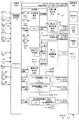
図5及び図6は、遊技機本体1の制御に用いられる各種制御基板及びそれに関連する構成要素を示すブロック図である。図5、図6には、制御基板として、主基板100、払出制御基板200、表示器制御基板300、ランプ制御基板400、音声制御基板500、発射制御基板600、電源基板700が示されている。ここで主基板100と表示器制御基板300は、全体として遊技制御手段を構成する。かかる遊技制御手段は、前記始動口21への球の入賞に基づいて、可変表示装置310の可変表示を実行する。
【0062】
最初に、図6に示す主基板100について説明する。
主基板100は、主基板内部のクロック回路108が生成するクロックを基準に動作する。またクロック回路108が生成したクロックを内部タイマー107で分周して得た一定時間間隔の割込み信号をCPU102に入力することで、一定時間ごとに当該CPU102をリセットする。CPU102は、リセット間隔よりも短い時間で終了するように分割した処理をリセットごとに実行することで一連の動作を遂行する。
【0063】
始動口スイッチ121、右普通図柄表示装置作動ゲートスイッチ126a、左普通図柄表示装置作動ゲートスイッチ126b、右袖入賞口スイッチ122a、左袖入賞口スイッチ122b、右落し入賞口スイッチ123a、左落し入賞口スイッチ123bは、それぞれ球の入賞を検知するためのスイッチであり、これらのスイッチからの入力信号は、ゲート回路110aに供給される。
【0064】
役物連続作動装置スイッチ124、カウントスイッチ125、左賞球検出スイッチ130a、右賞球検出スイッチ130b、シュート球切れスイッチ131、ガラス枠開放検出スイッチ132、オーバフロースイッチ133からの各入力信号は、ゲート回路110bに供給される。
【0065】
ゲート回路110a、110bのアドレスは、CPU102のアドレス空間にメモリマップドI/O方式で設定されている。CPU102が出力するアドレス信号及びライト/リードの制御信号を、CPU102が出力するシステムクロックに従って、アドレスデコード回路113でデコードすることによりチップセレクト信号を生成する。
【0066】
このチップセレクト信号にてゲート回路110a、110bがセレクトされると、始動口スイッチ121などからの各入力信号がゲート回路を通じてデータバスに出力される。データバス上の各入力信号は、一定時間ごとに発生する割込み信号によって、次にリセットされるまでの間に複数回検出されてチャタリング防止処理が行われた後、入力信号ごとに指定されたRAM領域に記憶される。
【0067】
始動口スイッチ121からの入力信号は5個賞球の賞球信号として、また右袖入賞口スイッチ122a、左袖入賞口スイッチ122b、右落し入賞口スイッチ123a、左落し入賞口スイッチ123bからの入力信号はそれぞれ8個賞球の賞球信号として、さらに役物連続作動装置スイッチ124、カウントスイッチ125からの入力信号は15個賞球の賞球信号として扱われ、それぞれのスイッチで検出された入賞個数が指定されたRAM領域に記憶される。またこれと同時に、賞球総数がCPU102で演算処理され、指定のRAM領域に記憶される。
【0068】
その他、始動口スイッチ121、右普通図柄表示装置作動ゲートスイッチ126a、左普通図柄表示装置作動ゲートスイッチ126bからの入力信号に対してそれぞれ乱数値がセットされ、これらの値がRAM領域に記憶される。このデータを基にして、遊技機本体1の遊技状態が設定され各制御基板にデータが出力される。
【0069】
各制御基板への出力データは、データバスの途中に設けたバッファ114を通り、さらに出力データバスを通してラッチ回路112a〜112gに出力される。出力用のラッチ回路とCPU102とを結ぶデータバスの途中にバッファ114を配置することでバス信号が一方向の流れになり、不正防止の対策となる。
【0070】
始動口スイッチ5個賞球RAM領域、左右袖入賞口スイッチ、左右落し入賞口スイッチ8個賞球RAM領域、役物連続作動装置スイッチ、カウントスイッチ15個賞球RAM領域にデータがあることにより、CPU102は、各賞球数に設定された8ビット賞球データを順次、データバス、出力データバスを通じてラッチ回路112aに出力する。これと同調するように払出制御基板200に対する割り込み信号、ストローブ信号の制御信号をデータバス、出力データバスを通じてラッチ回路112eに出力する。
【0071】
メモリマップドI/Oで制御されたアドレスデコード回路113でデコードして得たチップセレクト信号がラッチ回路112a、ラッチ回路112eに順次出力されると、8ビット賞球データがラッチ回路112aに、割込み信号、ストローブ信号の制御信号がラッチ回路112eにそれぞれラッチされ、8ビットパラレル賞球出力信号と割り込み信号、ストローブ信号の2ビットの制御信号で構成された出力信号が、払出制御基板に賞球データとして出力される。
【0072】
図7に示す払出制御基板200は、球排出機構を制御して、賞球データに対応した数の賞球排出を行うものである。排出した賞球の検知を、右賞球検出スイッチ130a、左賞球検出スイッチ130bで行い、その検出信号がゲート回路211に出力される。チップセレクト信号がアドレスデコード回路213からゲート回路211に出力されることにより、右賞球検出スイッチ130a、左賞球検出スイッチ130bの出力する検知信号がデータバス上に出力されCPU102に取り込まれる。
【0073】
これらの検出信号に基づいて、実際に払い出した賞球総数がCPU102で演算処理され、その値がRAM領域の記憶データから減算処理され、リアルタイムに賞球総数のデータが更新される。また排出賞球数の設定数ごとに出力信号がラッチ回路112fに出力され、アドレスデコード回路113のチップセレクト信号に同期して外部へパルス出力される。
【0074】
始動口スイッチ121、右普通図柄表示装置作動ゲートスイッチ126a、左普通図柄表示装置作動ゲートスイッチ126bの入力信号に対してそれぞれ乱数値を取得し、これに基づいてCPU102で遊技演出の種類(制御パターン)が決定され、遊技状態演出データが生成されてRAM領域に記憶される。この遊技状態演出データの記憶されるRAM領域が図柄情報記憶手段になっている。
【0075】
また、表示器制御基板300へは、前記遊技状態演出データに対応した停止図柄を定める左図柄データ、中図柄データ、右図柄データが時系列に表示演出データとして出力される。すなわち、CPU102から8ビット認識コード、表示状態演出8ビットデータが、データバスを通じてラッチ回路112bに順次出力されると、これらと同調するように表示器制御基板300への割り込み信号、各ストローブ信号の2ビット制御信号がラッチ回路112eへ出力される。
【0076】
これらの信号は、メモリマップドI/Oで制御されたアドレスデコード回路113からデコードされて出力されるチップセレクト信号に基づくタイミングで、順次ラッチ回路にラッチされてパラレル出力され、時系列に左図柄データ、中図柄データ、右図柄データや、変動停止データなどが表示演出データとして、表示器制御基板300に順次出力される。
【0077】
表示演出データに同調して、8ビットパラレルランプ表示出力データと制御信号が、ランプ制御表示基板400にラッチ回路112cを通じて出力される。また、表示演出データに同調して、8ビットパラレル音源出力データと制御信号が音声制御基板500にラッチ回路112dを通じて出力される。すなわち、各データがデータバスに出力されるタイミングに同調してアドレスデコード回路からチップセレクト信号が出力され、ラッチ回路112c、112dにデータバス上のデータがラッチされて、ランプ制御表示基板400などに出力される。
【0078】
遊技状態が特別遊技状態(大当たり)の場合、遊技状態演出データに同調して大入賞口ソレノイド134の制御データがラッチ回路112gに出力され、かつアドレスデコード回路113からのチップセレクト信号がラッチ回路112gに入力される。これによりラッチ回路112gから大入賞口ソレノイド134の制御データが出力され、大入賞口ソレノイド134が駆動され、大入賞口24が開閉状態になって球を大入賞口24に誘導可能となる。
【0079】
大入賞口24内部の特定領域に配置された役物連続作動装置スイッチ124が球を検知すると球検知信号が出力され、この信号がゲート回路110bを介してデータバスに出力されCPU102に取り込まれる。役物連続作動装置スイッチ124から出力された球検知信号に基づく検出処理の結果、方向切換ソレノイド135の制御データがラッチ回路112gに出力され、方向切換ソレノイド135が制動される。同時に役物連続作動装置スイッチ124から出力された球検知信号に基づき、大当たり状態を次回のラウンドへ継続するか否かを示すラウンド継続データがRAM領域に記憶される。
【0080】
方向切換ソレノイド135が制動されることにより、大入賞口24内に配置されたカウントスイッチ125で球が計数される。カウントスイッチ125で計数されたデータの総合計数が所定の数量に到達するとラッチ回路112gの出力データが変更され、大入賞口ソレノイド134、方向切換ソレノイド135が非能動状態になり、1回の大当たりラウンドが終了する。所定時間後、ラウンド継続データがラウンドの継続を示している場合には、上述した制御方法により大当たり状態ラウンドがさらに継続する。
【0081】
右普通図柄表示装置作動ゲートスイッチ126a、左普通図柄表示装置作動ゲートスイッチ126bからの入力信号に対してそれぞれ乱数値が取得される。この乱数値に基づいて、普通図柄表示装置140(普通図柄LED1、普通図柄LED2)の表示制御データが生成され、これがCPU102からデータバスを通じてラッチ回路112gに出力される。そしてアドレスデコード回路113からチップセレクト信号が出力されるごとに普通図柄LED表示が一定時間行われる。
【0082】
乱数値の取得結果が当たりの場合には、前記始動口21の各可動片を作動させる電動役物Aソレノイド136A、電動役物Bソレノイド136Bの制動データが、CPU102からラッチ回路112gに出力されると共に、アドレスデコード回路113からのチップセレクト信号に応じてラッチ回路112gから一定時間出力されて電動役物Aソレノイド136A、電動役物Bソレノイド136Bが制御される。それにより、遊技盤2において球が始動口21に入賞し易い状態が発生する。
【0083】
主基板100に電源が供給されると、電源基板700よりリセット信号が供給され主基板100の各デバイスはリセット状態になる。その後システムリセット信号が非能動状態となり、各デバイスは能動状態に遷移する。システムリセット信号が非能動状態に信号変化するとクロック同期、遅延回路109による遅延処理により一定時間の経過後にワンチップマイコン101へのリセット信号が非能動となる。これによりワンチップマイコン101が稼動状態になり、主基板100の動作状態が保たれる。その後、ワンチップマイコン101の初期設定が行われる。
【0084】
遊技機外部供給の電源が不安定な場合には、電源基板700から停電検出信号がワンチップマイコン101のNMI(ノンマスカブルインターラプト)105に供給され、ワンチップマイコン101において各記憶領域の退避動作が行われる。
【0085】
具体的には、一定時間にわたって賞球検出データの検知を行った後、RAM領域に停電処理判定のデータを保存し、RAM104の保護を行う。すなわち、電源電圧が低下する事で、電源基板700からRAM104にバックアップ電源DC5VBBが供給され、RAM104の記憶状態が保持される。
【0086】
電源が次に供給されたとき、停電処理判定のデータの有無に基づき停電処理のあったことを認識すると、ワンチップマイコン101は停電復旧処理を行う。初期設定の時、RAM初期化信号が能動状態であれば、CPU102はI/Oポート106のデータを検出してRAM領域の初期化を行う。
【0087】
シュート球切れスイッチ131で球切れを検知した信号及びオーバフロースイッチ133で遊技盤面の下皿にて賞球の球詰まりを検出した信号は、ゲート回路110b及びデータバスを通じてワンチップマイコン101に取り込まれる。これらの信号は、データ変換後、ラッチ回路112aから賞球出力データと同じ構成にて払出制御基板200へ出力される。該ラッチ回路112a〜112gの出力は、一方向であり、不可逆性の出力形態をとる。
【0088】
主基板100は、主基板内部のクロック回路108が生成するクロックを基準に動作する。また内部タイマー107は、分周動作により一定時間間隔で割込み信号をCPU102に発生する。CPU102は、当該割り込み信号が入力される一定時間ごとに各種処理を行うようになっている。
【0089】
次に、図7に示す払出制御基盤200について説明する。
払出制御基板200は、主基板100から受信のみの一方向通信を行い、8ビットパラレル賞球データ、賞球データ制御信号1、賞球データ制御信号2で構成された通信データを受信する。
【0090】
賞球データ制御信号1が、ワンチップマイコン201のカウンタ回路202に入力されると、当該カウンタ回路202からCPU203に割り込み信号が出力される。これにより、賞球データ制御信号1は、CPU203に対して賞球データの取り込みをトリガーとする。
【0091】
CPU203は、アドレスデコード回路213を通じてチップセレクト信号をゲート回路212、ゲート回路211に出力し、ゲート回路212、211に入力されている賞球データや各種の信号をゲート回路及びデータバスを介して取り込み、RAM205に保存する。そして、取り込んだ賞球データに対応する賞球数で順次、払出動作を行う。
【0092】
CPU203は、賞球経路切換信号をデータバスを通じてラッチ回路215に出力し、これと同時にアドレスデコード回路213からチップセレクト信号を出力させる。これにより賞球経路切換信号がソレノイド224に出力され、払出動作の賞球経路確保が行われる。その後、ラッチ回路214に払出停止ソレノイド信号の停止解除信号を出力し、払出モータ222に払出モータ制御信号1,2,3,4を順次出力し、チップセレクト信号の出力タイミングによりモータ回転の制御をしながら賞球払出動作を行う。
【0093】
クロック回路209のクロックを基準に、内部タイマー208で一定時間間隔の割込み信号をCPU203に対して生成し、この割込みタイミングで賞球払出球の検出信号をデータバスに取り込み、所定の賞球数を検出したとき、払出停止ソレノイド223、払出モータ222の駆動を停止する。なお、賞球払出球の検出は、球貸し経路に設置された右賞球検出スイッチ130b、左賞球検出スイッチ130aで行われ、これらの検出信号はゲート回路211にチップセレクト信号を出力することでデータバスに取り込まれる。
【0094】
球貸し動作は、カードユニット(CR球貸機)bとの間で球貸し信号を、ゲート回路211、ラッチ回路215を通して送受信することにより行われる。球貸し動作時、CPU203はラッチ回路215を通して球貸し経路切換信号を経路切換ソレノイド224に出力して球貸し経路を確保し、球貸し経路に設置された右貸し球検出スイッチ220a、左貸し球検出スイッチ220bで貸し球の検出を行い、払出動作を行う。
【0095】
球貸し動作において、一定数ごとにラッチ回路215から外部へ情報出力される。また、球貸し信号の送受信が正常な状態において、ラッチ回路215から、発射制御基板600に対して発射許可信号が能動状態で出力される。また球貸し信号の送受信に異常が発生すると、発射許可信号は非能動状態に変化し、球発射不可能な状態になる。しかし、球貸し信号の送受信が正常な状態に復帰することで、発射可能となる。
【0096】
その他、払出動作においては、主基板100から、賞球データにシュート球切れスイッチ131のシュート球切れ信号、及び遊技機本体1の下受け皿4に設置されたオーバフロースイッチ133のオーバフロー信号が送信されると、払出制御基板200は払出動作を停止する。また賞球データに各解除信号が送信されることにより払出動作を再開する。
【0097】
払出制御基板200に電源が供給されると、電源基板700よりシステムリセット信号が供給され、払出制御基板200の各デバイスはリセット状態になる。その後、リセット信号が非能動状態で、各デバイスは能動状態に遷移する。
【0098】
クロック同期・遅延回路210の遅延処理により、ワンチップマイコン201へのリセット信号は、元のリセット信号が非能動状態に信号変化してから一定時間の経過後に非能動になる。こうして元のリセット信号が非能動状態になってから一定時間の経過後に、ワンチップマイコン201は稼動状態になり、払出制御基板200の動作状態が保たれる。その後、ワンチップマイコン201の初期設定が行われる。
【0099】
遊技機外部供給の電源が不安定な場合には、電源基板700からワンチップマイコン201のNMI(ノンマスカブルインターラプト)206に停電検出信号が供給され、ワンチップマイコン201において各記憶領域の退避動作が行われる。具体的には、一定時間にわたって賞球検出データの検知を行った後、RAM領域に停電処理判定のデータを保存し、RAM205の保護を行う。
【0100】
電源電圧が低下する場合は、電源基板700からRAM205にバックアップ電源としてDC5VBBが供給され、RAM205の記憶状態が保持される。再度電源供給がされたとき、停電処理判定のデータの存在を認識することで、ワンチップマイコン201は停電復旧処理を行う。初期設定の時、RAM初期化信号が能動状態であれば、CPU203はI/Oポート106のデータを検出して、RAM領域の初期化を行う。
【0101】
次に、図8に示す表示器制御基板300について説明する。
表示器制御基板(遊技制御手段)300は、遊技盤2上に設置された可変表示装置310の制御を主に行う。表示器制御基板300は、所定の画像処理手順(プログラム)や画像制御データを記憶している表示器制御ROM302と、所定の画像処理手順を読み取り実行する表示器制御CPU301を有している。
【0102】
また表示器制御基板300は、前記表示器制御CPU301によって画像処理手順を実行することで取得した情報を記憶するための表示器制御RAM303と、主基板100からの指示情報や表示器制御基板内の各制御ICなどと入出力を行うための入出力インターフェース306と、表示器制御CPU301によって、入出力インターフェース306を介して制御指示情報を取得し、具体的な画像を生成する画像制御IC304を有している。
【0103】
さらに表示器制御基板300は、画像制御IC304に管理され、多種多様な画像をデータ化し記憶している画像データROM305と、前記表示器制御CPU301が正常に動作し画像が表示されていることを確認するための信号を外部に出力するための試射試験端子307などを有している。
【0104】
表示器制御CPU301には、入出力インターフェース306を介して、主基板100からパラレル通信によって指示情報が入力される。表示器制御CPU301は、入力された指示情報の内容を、表示器制御ROM302に記憶されている画像処理手順に従って実行し、表示器制御RAM303に情報を整理して格納しながら、画像制御IC304へ具体的な指示を行う。
【0105】
画像制御IC304は、表示器制御CPU301の指示に従い、画像データROM305を参照して、具体的な映像信号を生成し、表示装置へ出力する。図8のブロック図では、画像制御IC304が生成した画像データやパレット(色)情報などを一時的に記憶しておく領域であるVRAMが図示されていないが、画像制御IC304の内部にVRAMを内蔵したワンチップマイコンで構成してもよい。
【0106】
電源基板700からのリセット信号は、遊技機本体1に電源が投入されると、電源基板700から表示器制御CPU301に入力される。その後、表示器制御CPU301は、表示器制御ROM302に記憶されている画像制御手順に従って、表示器制御基板300内の各制御回路の初期化を行う。
【0107】
次に、図9に示すランプ制御基板400について説明する。
ランプ制御基板400は、遊技機本体1の前面や遊技盤2上に設置された遊技機状態ランプ422、サイドケースランプ423、各種LED424,426〜428,420,421などの点灯制御を行うものである。
【0108】
ランプ制御基板400は、所定のランプ制御処理手順(プログラム)や制御データを記憶しているランプ制御ROM402と、所定のランプ制御処理手順を読み取り実行するランプ制御CPU401と、ランプ制御CPU401によってランプ制御処理手順を実行することで取得した情報を記憶するランプ制御RAM403と、主基板100からの指示情報やランプ制御基板400内の各制御回路などと入出力を行うための入出力インターフェース404と、ランプ制御CPU401によって入出力インターフェースを介してランプ制御基板400と接続している各ランプ・LEDの点灯信号を、駆動させるためのドライバー回路405などで構成されている。
【0109】
ランプ制御CPU401には、入出力インターフェース404を介して、主基板100からパラレル通信により指示情報が入力される。ランプ制御CPU401は、入力された指示情報の内容をランプ制御ROM402に記憶されているランプ制御処理手順に従って実行し、ランプ制御RAM403に情報を整理して格納しながら、ドライバー回路405を動作させ、接続されている各ランプ・LEDの点灯・消灯を行う。
【0110】
電源基板700からのリセット信号は、遊技機本体1に電源が投入されると、電源基板700からランプ制御CPU401に入力される。そして、ランプ制御CPU401は、ランプ制御ROM402に記憶されている制御手順に従って、ランプ制御基板内の各制御回路の初期化を行う。
【0111】
次に、図10に示す音声制御基板500について説明する。
音声制御基板500は、遊技機本体1が遊技状態にある時、ゲーム演出による効果音や音声などの制御を行うものである。また、遊技状態でない場合は、遊技機本体1の異常状態を知らせるための警告音などの制御を行う。
【0112】
音声制御基板500は、所定の音声処理手順(プログラム)や制御データを記憶している音声制御ROM502と、所定の音声制御手順を読み取り実行する音声制御CPU501と、音声制御CPU501により音声処理手順を実行して取得した情報を記憶する音声制御RAM503と、主基板100からの指示情報や音声制御基板500内の各制御ICなどと入出力を行うための入出力インターフェース506と、音声制御CPU501により入出力インターフェースを介し制御指示情報を取得して具体的な音声を生成する音声制御IC504と、音声制御IC504に管理され、多種多様な音声をデータ化し記憶している音声データROM505と、音声制御IC501から生成された音声信号を増幅するアンプ回路507から構成される。
【0113】
音声制御CPU501は、入出力インターフェース506を介して、主基板100からパラレル通信により指示情報が入力される。音声制御CPU501は、入力された指示情報の内容を音声制御ROM502に記憶されている音声制御手順に従って実行し、音声制御RAM503に情報を整理して格納しながら、音声制御IC504へ具体的な指示を行う。
【0114】
音声制御IC504は、音声制御CPU501の指示に従い、音声データROM505を参照し、具体的な音声の信号を生成しアンプ回路507へ出力する。電源基板からのリセット信号は、パチンコ機に電源が投入されると、該電源基板700から音声制御CPU501に入力され、音声制御CPU501は音声制御ROM503に記憶されている音声制御手順に従い、音声制御基板内の各制御回路の初期化を行う。
【0115】
次に、図11に示す発射制御基板600について説明する。
発射制御基板600は、発射モータ653に使用されているパルスモータの回転数を、所定の回転数にするためのパルスを生成する回路である発振回路601と、分周回路602と、ハンドル部650内のタッチセンサ651からの信号、ストップスイッチ652からの信号、電源基板700からのリセット信号、そして、前記払出制御基板200からの発射許可信号を判断し、発射モータ駆動信号を生成するモータ駆動信号制御回路603と、パルスモータ(発射モータ653)の各コイルに励磁させるためのドライバー回路604などから構成されている。
【0116】
前記ハンドル部650は、遊技者がハンドル5に触れているか否かを検出するタッチセンサ651、遊技者が任意に球の発射を停止できるようにするストップスイッチ652、球を発射させるためのパルスモータ653(発射モータ)などで構成されている。
【0117】
電源基板700からのリセット信号は、遊技機本体1に電源が投入されると、電源基板700からモータ駆動信号制御回路603へ入力され、発射制御基板600の各回路を初期化する。
【0118】
ハンドル部650内のタッチセンサ651は、遊技者がハンドル5に触れている状態であれば発射が可能であるとみなす信号を出力し、遊技者がハンドル5に触れていない状態であれば、発射が不可能であるとみなす信号をモータ駆動信号制御回路603にそれぞれ出力する。
【0119】
ストップスイッチ652は、遊技者が任意に球の発射を停止することができるように設けたスイッチであり、遊技者によりストップスイッチ652の操作がされた場合に、モータ駆動信号制御回路603に球の発射停止信号を出力し、ストップスイッチ652の入力がない場合に、球の発射信号を出力する。
【0120】
また、ストップスイッチ652は、遊技者から何らストップスイッチ652に対し操作がなく、ハンドル5を回転させた状態にない場合には、ストップスイッチ652から入力がされた状態と同じ信号を出力する。すなわち、ハンドル5内部の構造上、ハンドル5が回転していない状態ではストップスイッチ652からの信号が入力されている状態になるようになっている。つまり、遊技機本体1に電源が投入され、前記リセット信号がモータ駆動信号制御回路603に入力され、各回路の初期化が行われた後、遊技者がハンドル5に触れて回転させた状態になって初めて球が発射される。
【0121】
次に、図12に示す電源基板700について説明する。
外部から供給されるAC24Vをダイオードブリッジ整流器で全波整流を行い、直流電源DC24Vを生成する。DC24V電源にダイオードを通してコンデンサーで平滑を行い、DC32V電源を生成する。DC24V、DC32Vは非安定電源である。
【0122】
DC24Vを電源回路701に供給して、安定電源DC18V、DC12V、DC5Vの定電圧電源が生成され、前記主基板100、前記払出制御基板200、前記ランプ制御基板400、前記音声制御基板500、前記表示器制御基板300、前記発射制御基板600に供給される。
【0123】
生成されたDC5Vの定電圧電源を、ダイオードを通してバックアップ回路702のコンデンサーに接続して、DC5VBBのバックアップ電源を生成し、DC5VBBが主基板100、前記払出制御基板200に供給される。前記AC24Vはカードユニット接続基板900に供給され、前記払出制御基板200とカードユニットbの通信用電源、操作パネル基板aの電源に使用される。
【0124】
DC24V電源の電圧レベルを電圧検出回路708で検出して遅延回路707に出力する。遅延回路707は内部時定数500ミリsecの遅延時間をもち、電圧検出回路708の連続出力時間が遅延回路707の時定数より大きくないと遅延回路707は出力信号を出力しない。この為、DC24V電源の電圧レベルが遅延回路707の時定数より小さい時間の電圧変動及び電源停止は無視され停電検出信号は電源基板より外部に出力されない。
【0125】
遅延回路707に時定数より大きな入力信号があると、遅延回路707は停電検出信号を前記主基板100、前記払出制御基板200、シフトレジスタ704のシリアル入力端子に出力する。8ビットシフトレジスタ704は、クロック回路706より周期20ミリsecのクロックが常時入力されている。
【0126】
ここで8ビットのデータ入力端子はゼロに固定している。この為、停電検出信号が8ビットシフトレジスタ704に入力すると、8クロック(約160ミリsec)後8ビットシフトレジスタ704からリセット信号が前記主基板100、前記払出制御基板200、前記発射制御基板600、前記表示器制御基板300、前記ランプ制御基板400、前記音声制御基板500に出力される。
【0127】
電源立ち上げ時及び停電復帰後、周辺回路電源立ち上げ時より遅延回路707の時定数の時間、停電検出信号及びリセット信号は能動状態で出力している。遅延回路707の時定数の時間後、停電検出信号は非能動状態になり、リセット信号は、8ビットシフトレジスタ704の8クロック後非能動状態で出力される。RAM初期化信号は、RAM初期化スイッチ705を手動で押すことにより能動状態で前記主基板100、前記払出制御基板200に出力される。
【0128】
次に遊技機の作用について説明する。
図13は、遊技機本体1のうち表示遊技の実行にかかわる部分の概略機能構成と表示遊技の流れを示している。始動口21へ入賞した球は、始動手段としての始動口スイッチ121によって検出される。乱数発生手段1301は乱数(たとえば0〜316の中の何れかの数字)を一定間隔で継続的に発生し、乱数取得手段1302は、始動手段が球を検出したとき乱数発生手段1301から大当たり乱数としての乱数値(大当たり乱数値)を取得する。なお、これと同時に乱数取得手段1302は、図示省略の大当たり図柄乱数発生手段から大当たり図柄乱数としての乱数値(大当たり図柄乱数値)を取得するようになっている。また、RAM領域である図柄情報記憶手段には、以前の表示遊技の実行結果に係る図柄情報が記憶されている。その記憶されている図柄情報に基づいて継続回数管理手段1309は、リーチ態様が継続し得る継続回数を設定する。
【0129】
具体的には、継続回数管理手段1309は、表示遊技において特定の図柄情報が停止表示すると、その特定の図柄情報に基づいてリーチ態様の継続回数を設定し、表示遊技がリーチ態様から実行される実行回数をカウントし、実行回数が継続回数に一致すると、継続回数を初期化する。
【0130】
さらにリーチ継続乱数発生手段1303は、乱数(たとえば0〜316の中の何れかの数字)を一定間隔で継続的に発生し、リーチ継続乱数取得手段1304は、始動手段が球を検出したときリーチ継続乱数発生手段1303からリーチ継続乱数としての乱数値(リーチ継続乱数値)を取得する。
【0131】
乱数値記憶手段1305は、乱数取得手段1302の取得した大当たり乱数値と大当たり図柄乱数値とリーチ継続乱数取得手段1304の取得したリーチ継続乱数値とを組にしたものを最大4個まで記憶し得る先入れ先出し形式のメモリである。乱数値記憶手段1305に記憶されている乱数値は、表示遊技を開始する際に読み出される。乱数判定手段1306は、乱数値記憶手段1305から読み出された大当たり乱数値と所定の大当たり判定値(当たり乱数)とを比較し、大当たりか否かを判定するものである。またリーチ継続乱数判定手段1308は、乱数値記憶手段1305から読み出されたリーチ継続乱数値と所定のリーチ継続判定値(リーチ継続乱数)とを比較し、リーチ態様からの継続か否かを判定するものである。
【0132】
判定基準変更手段1307は、乱数判定手段1306が大当たり乱数値と大当たり判定値とを比較して判定する際の判定基準を変更するものである。より詳細には、判定基準変更手段1307は、判定基準を、少なくとも低確率基準と高確率基準のいずれかに切り換えるようになっている。ここで、高確率基準は、乱数判定手段1306が乱数値を当たり乱数と判定する確率が低確率基準より高くなる判定基準である。たとえば、低確率基準の場合には、0〜316の中の1つの数値が大当たり判定値として設定され、高確率基準の場合には、0〜316の中の5つの数値が大当たり判定値として設定される。判定基準変更手段1307は、現在いずれの判定基準を設定しているか記憶しておき、所定の変更条件が成立したか否かを監視し、変更条件の成立に基づいて判定基準を切り換えるようになっている。
【0133】
今回の大当たり乱数値が、設定されている判定基準の中のいずれかの大当たり判定値と一致する場合には、当該乱数値と組になっている大当たり図柄乱数値に従って表示遊技の最終的な表示結果となる表示態様が定められる。また大当たり図柄乱数値が特定図柄(たとえば「777」)に対応する特定値であるか否かによって場合分けし、さらに判定基準が低確率基準であるか高確率基準であるかとリーチ継続乱数値がリーチ継続判定値と一致しているか否かによって場合分けし、それぞれの場合に対応して予め定めた複数種類の変動パターンの中から今回の表示遊技に用いる可変表示の変動パターンを乱数処理によって選択する。
【0134】
判定基準変更手段1307は、乱数判定手段1306の判定基準が低確率基準に設定されている状態において、大当たり図柄乱数値が特定図柄に対応する特定値となった場合には、今回の表示遊技の終了後、乱数判定手段1306の判定基準を高確率基準に変更する。判定基準変更手段1307は、乱数判定手段1306の判定基準が高確率基準に設定されている間に表示遊技が10000回実行されたとき、もしくは大当たり乱数値が大当たり判定値であって大当たり図柄乱数値が特定値でない状態で表示遊技が実行されたとき、乱数判定手段1306の判定基準を高確率基準から低確率基準に変更する。なお大入賞口24が開いている間は、上記にかかわらず、低確率基準に設定される。
【0135】
大当たり乱数値が大当たり判定値でない場合には、特別停止結果態様にならないように表示結果の表示態様が選択されるとともに、それに至る変動パターンが選択される。より詳細には、判定基準が低確率基準であるか高確率基準であるかによって場合分けし、さらに左図柄と右図柄の関係(リーチ態様になるか否か)と中図柄と左右図柄との関係(リーチ態様になる場合であって中図柄と左右図柄とが一致する場合には、中図柄を乱数処理により左右図柄と異なるものに変える)とによって場合分けし、さらにリーチ継続乱数値がリーチ継続判定値と一致しているか否かによって場合分けし、それぞれの場合に対応して予め定めた複数種類の変動パターンの中から今回の表示遊技における可変表示の変動パターンを乱数処理によって選択する。
【0136】
すなわち、大当たり乱数値が大当たり判定値であるか否かにかかわらず、乱数判定手段1306の判定基準が高確率基準に設定されている場合であってリーチ継続乱数値がリーチ継続判定値と一致する場合には、表示遊技の実行回数が継続回数と一致するまで、表示遊技がリーチ態様1312から開始する変動パターンが選択される。一方、乱数判定手段1306の判定基準が低確率基準に設定されている場合には、表示遊技が初期画面1311から開始する変動パターンが選択される。こうして定めた停止態様や変動パターンに基づいて表示遊技が実行される。
【0137】
表示遊技の流れとしては、初期画面1311からリーチ態様1312を経て大当たり1313になる場合、初期画面1311からリーチ態様1312を経たのち、一旦不利な表示態様となり、再変動1314した後、大当たり1313になる場合がある。また初期画面1311からリーチ態様1312を経て外れ1315になる場合と、初期画面1311からリーチ態様1312を経ずに外れ1315になる場合がある。さらにリーチ態様1312から開始する場合がある。
【0138】
図14は、可変表示装置310で展開される表示遊技の流れの一例を示している。表示遊技が初期状態から開始する場合には、図14aに示すように、可変表示装置310に表示されている3つの表示部311〜313において識別情報が変動を開始する。しばらくすると、いずれかの表示部から順に、一の識別情報が停止表示される。同図bでは、3つのうちの左表示部311に「7」の識別情報が停止表示した状態を、同図cでは、左表示部311と右表示部313に「7」の識別情報が停止表示してリーチ態様が形成されている。なお、前述したように表示遊技がリーチ態様から開始される場合には、図14cに示す状態から表示遊技が開始する。
【0139】
その後、中表示部312において図柄が停止表示し、図14dに示すように、表示遊技の結果が最終的に「777」などの特別停止結果態様に確定した場合は、特別遊技状態として大入賞口24の開閉動作が最大で15回繰り返される。一方、図14eに示すように、不利な表示態様に終わった場合には、通常は、今回の表示遊技が終了する。なお、一旦、不利な表示態様となった後に、再変動して、特別停止結果態様に移行する場合もある。
【0140】
このように、表示遊技がリーチ態様から開始する場合を有しているので、遊技者の期待と興奮を、表示遊技の開始直後から喚起することが可能になる。また、乱数の判定基準が高確率基準に設定されている間においても表示遊技がリーチ態様から開始する場合と開始しない場合があるので、次回の表示遊技がリーチ態様から開始するか否かにも遊技者の期待と関心が注がれ、遊技内容がより一層変化に富むものになる。特に、当たりが高確率で出現する状態に設定されているときに表示遊技がリーチ態様から開始する場合を設定したので、特別停止結果態様の発生に対する遊技者の期待と興奮を高いレベルで維持することができるとともに、表示遊技を時間短縮して実行することができ、早期に大当たりに導くことができる。
【0141】
図15は、リーチ継続乱数値の取得および判定を表示遊技の実行開始時に行う場合の機能構成を示している。始動口21へ球が入賞した際には、大当たり乱数値と大当たり図柄乱数値とを取得して、乱数値記憶手段1305に記憶する。
【0142】
表示遊技を開始する際には、乱数値記憶手段1305から乱数値を読み出し、乱数判定手段1306による判定を行うとともに、リーチ継続乱数取得手段1304がリーチ継続乱数発生手段1303からリーチ継続乱数値を取得し、これをリーチ継続乱数判定手段1308によってリーチ継続判定値と比較し、リーチ継続になるか否かを判定するようになっている。
【0143】
以上、本発明の実施形態を図面によって説明してきたが、具体的な構成はこれら実施形態に限られるものではなく、本発明の要旨を逸脱しない範囲における変更や追加があっても本発明に含まれる。
【0144】
たとえば、実施の形態では、球が始動口へ入賞した際に大当たり乱数値を取得してこれを記憶しておき、表示遊技の実行を開始する段階で、大当たり乱数値が大当たり判定値か否かの判定を行うようにしたが、球が始動口へ入賞した際に乱数値を取得するとともに、大当たり判定値か否かの判定を行い、その判定結果を乱数値記憶手段1305に記憶するように構成してもよい。さらにこの時点で表示遊技の実行結果の表示態様を構成する停止図柄の選定を行い、判定結果と停止図柄の双方を記憶するようにしてもよい。また高確率基準と低確率基準とを切り換える際の契機は、実施の形態に示したものに限定されない。
【0145】
このほか実施の形態では識別情報として数字の図柄を用いたが、各種の文字や記号あるいは動物や植物などの絵柄等を識別情報として用いてもよい。また上記の実施の形態では、本発明をパチンコ機について説明したが、プログラム制御される、スマートボールゲーム機、アレンジボールゲーム機といった遊技機にも同様に本発明を適用することができる。このような各場合においても、上記実施の形態と同様な効果が奏される。
【0146】
さらに、表示遊技がリーチ態様から図柄変動開始するモードになると、表示遊技の実行回数が継続回数を超えるまでは、表示遊技がリーチ態様から開始するモードが継続するものを示したが、継続回数管理手段の設定する継続回数はこれに限らない。例えば、大当たりになるまで、すなわち、図14dに示すように中表示部312において図柄「7」が停止表示し、表示遊技の結果が最終的に「777」等の特別停止結果態様になるまで、表示遊技がリーチ態様から図柄変動開始するモードが継続するようにしてもよい。この場合、リーチ態様から図柄変動開始するモードが始まってから大当たりになって当該モードが終了するまでに実行された回数が継続回数になる。
【0147】
さらに、表示遊技がリーチ態様から図柄変動開始するモード中に、表示遊技の中止を表象するような表象図柄(中止図柄)が停止表示されると、表示遊技が初期状態から図柄変動開始するモードになるようにしてもよい。すなわち、表象図柄(中止図柄)が停止表示するか、表示遊技の実行回数が継続回数を超えるまで表示遊技がリーチ態様から開始するようにしてもよい。この場合、リーチ態様から図柄変動開始するモードが始まってから当該モードが終了するまでに実行された回数が継続回数になる。
【0148】
なお、継続回数管理手段の設定する継続回数が前述したどの種類の継続回数に属するかは、表示遊技の表示結果に係る図柄情報に基づくものである。
【0149】
さらに、前記実施の形態では、表示遊技をリーチ態様から継続して開始される場合に、その継続回数は、以前の表示遊技の実行結果に係る図柄情報で図柄情報記憶手段に記憶されているものに基づき継続回数管理手段1309によって設定されるものを示したが、以前の表示遊技の実行結果がリーチ態様で終了し、そのリーチ態様に係るリーチ図柄が点滅で報知されるとき、その報知された態様に基づき継続回数管理手段1309によって設定されるようにしてもよい。
【0150】
さらに、普通図柄表示装置140の変動表示結果に係る普通図柄情報を普通図柄情報記憶手段が記憶するようにし、乱数判定手段1306の判定基準が高確率基準に設定されている場合であってリーチ継続乱数値がリーチ継続判定値と一致する場合には、普通図柄情報に基づいて設定された継続回数分だけ、表示遊技をリーチ態様から開始するようにしてもよい。なお、リーチ継続乱数判定手段1308の判定結果がリーチ継続乱数であるか否かの判断は、前記実施の形態と同じく、表示遊技を開始する段階であってもよく、球が始動口へ入賞したときであってもよい。特定普通図柄情報は、例えば「7」の数字やキャラクタ図柄などである。
【0151】
【発明の効果】
本発明にかかる遊技機によれば、以前の表示遊技の実行結果に係る図柄情報に基づいて、継続回数管理手段がリーチ態様の継続し得る継続回数を設定し、継続回数分だけ表示遊技がリーチ態様から開始する場合を有しているので、遊技者の期待と興奮を、表示遊技の開始直後から喚起することが可能になる。また、乱数の判定基準が高確率基準に設定されている間においても表示遊技がリーチ態様から開始する場合と開始しない場合があるので、次回の表示遊技がリーチ態様から開始するか否かにも遊技者の期待と関心が注がれ、遊技内容がより一層変化に富むものになり、スリルと興奮に満ちた遊技を提供することができる。特に、当たりが高確率で出現する状態に設定されているときに継続回数分だけ表示遊技がリーチ態様から開始する場合を設定したので、特別停止結果態様の発生に対する遊技者の期待と興奮を高いレベルで維持することができる。
【図面の簡単な説明】
【図1】本発明の一実施の形態に係る遊技機を示す正面図である。
【図2】本発明の一実施の形態に係る遊技機の内部構造を示す背面図である。
【図3】本発明の一実施の形態に係る遊技機の遊技盤を拡大して示す正面図である。
【図4】本発明の一実施の形態に係る遊技機の遊技盤裏面側を拡大して示す背面図である。
【図5】本発明の実施の形態に係る遊技機の回路構成全体を示すブロック図である。
【図6】本発明の実施の形態に係る遊技機の有する主基板の回路構成を示すブロック図である。
【図7】本発明の実施の形態に係る遊技機の有する払出制御基板の回路構成を示すブロック図である。
【図8】本発明の実施の形態に係る遊技機の有する表示器制御基板の回路構成を示すブロック図である。
【図9】本発明の実施の形態に係る遊技機の有するランプ制御基板の回路構成を示すブロック図である。
【図10】本発明の実施の形態に係る遊技機の有する音声制御基板の回路構成を示すブロック図である。
【図11】本発明の実施の形態に係る遊技機の有する発射制御基板の回路構成を示すブロック図である。
【図12】本発明の実施の形態に係る遊技機の有する電源基板の回路構成を示すブロック図である。
【図13】本発明の実施の形態に係る遊技機のうち表示遊技の実行にかかわる部分の概略機能構成と表示遊技の流れを示す説明図である。
【図14】本発明の実施の形態に係る遊技機の可変表示装置で展開される表示遊技の流れを示す説明図である。
【図15】本発明の実施の形態に係る遊技機であってリーチ継続乱数値を表示遊技の実行開始時に取得するものの概略機能構成と表示遊技の流れを示す説明図である。
【符号の説明】
1…遊技機本体
2…遊技盤
3…上受け皿
4…下受け皿
5…ハンドル
6…灰皿
7…上受け皿球抜きレバー
8…下受け皿球抜きレバー
9…貸出ボタン
10…返却ボタン
11…ガラス枠
12…度数表示部
15…風車
16…誘導レール
21…始動口
22a…右袖入賞口
22b…左袖入賞口
23a…右落し入賞口
23b…左落し入賞口
24…大入賞口
29…アウト口
100…主基板
101…ワンチップマイコン
102…CPU
103…ROM
104…RAM
105…NMI
106…I/Oポート
107…内部タイマー
108…クロック回路
109…クロック同期・遅延回路
110a、110b…ゲート回路
112a〜112g…ラッチ回路
113…アドレスデコード回路
114…バッファ
115…リセット
116…試射試験信号端子
121…始動口スイッチ
122a…右袖入賞口スイッチ
122b…左袖入賞口スイッチ
123a…右落し入賞口スイッチ
123b…左落し入賞口スイッチ
124…役物連続作動装置スイッチ
125…カウントスイッチ
126…普通図柄表示装置作動ゲートスイッチ
126a…右普通図柄表示装置作動ゲートスイッチ
126b…左普通図柄表示装置作動ゲートスイッチ
130…賞球検出スイッチ
130a…右賞球検出スイッチ
130b…左賞球検出スイッチ
131…シュート球切れスイッチ
132…ガラス枠開放検出スイッチ
133…オーバフロースイッチ
134…大入賞口ソレノイド
135…方向切換ソレノイド
136…普通電動役物ソレノイド
140…普通図柄表示装置
200…払出制御基板
201…ワンチップマイコン
202…カウンタ回路
203…CPU
204…ROM
205…RAM
206…NMI
207…I/Oポート
208…内部タイマー
209…クロック回路
210…クロック同期・遅延回路
211、212…ゲート回路
213…アドレスデコード回路
214、215…ラッチ回路
216…リセット
220…球貸し検出スイッチ
220a…右球貸し検出スイッチ
220b…左球貸し検出スイッチ
222…払出モータ
223…払出停止ソレノイド
224…経路切換ソレノイド
300…表示器制御基板
301…表示器制御CPU
302…表示器制御ROM
303…表示器制御RAM
304…画像制御IC
305…画像データROM
306…入出力インターフェース
307…試射試験信号端子
310…可変表示装置
311…左表示部
312…中表示部
313…右表示部
400…ランプ制御基板
401…ランプ制御CPU
402…ランプ制御ROM
403…ランプ制御RAM
404…入出力インターフェース
405…ドライバー回路
420…特別図柄保留LED
421…普通図柄保留LED
422…遊技機状態ランプ
423…サイドケースランプ
424…遊技枠状態ランプ
426…ゲートLED
427…アタッカーLED
428…サイドLED
500…音声制御基板
501…音声制御CPU
502…音声制御ROM
503…音声制御RAM
504…音声制御IC
505…音声データROM
506…入出力インターフェース
507…アンプ回路
510…スピーカー
600…発射制御基板
601…発振回路
602…分周回路
603…モータ駆動信号制御回路
604…ドライバー回路
650…ハンドル部
651…タッチセンサ
652…発射停止スイッチ
653…発射モータ
700…電源基板
701…定電圧電源装置
702…バックアップ電源
703…電圧検出回路
704…シフトレジスタ
705…RAM初期化スイッチ
706…クロック回路
707…遅延回路
708…電圧検出回路
709…停電検出回路
800…枠用外部端子板
801…賞球タンク球有無スイッチ
850…盤用外部端子板
900…カードユニット接続基板
1301…乱数発生手段
1302…乱数取得手段
1303…リーチ継続乱数発生手段
1304…リーチ継続乱数取得手段
1308…リーチ継続乱数判定手段
1305…乱数値記憶手段
1306…乱数判定手段
1307…判定基準変更手段
1309…継続回数管理手段
1311…初期画面
1312…リーチ態様
1313…大当たり
1314…再変動
1315…外れ
a…操作パネル基板
b…カードユニット
c…電源AC24V[0001]
TECHNICAL FIELD OF THE INVENTION
The present invention includes a variable display device capable of variably displaying a plurality of pieces of identification information, and display control means for performing display control of the variable display device, and variably displays the identification information on the variable display device based on satisfaction of a predetermined condition. When the display game in which the variable display is stopped and the plurality of pieces of identification information are stopped and displayed is executed, and the display mode of the execution result of the display game becomes a special stop result mode which is a combination of predetermined identification information, The present invention relates to a gaming machine that generates a special gaming state in which a predetermined gaming value can be given to a player.
[0002]
[Prior art]
A pachinko machine called a fever machine has been generally known as a game machine of this type. In the fever machine, when a ball hitting a game area formed on a game board wins a starting port, identification information such as various symbols is variably displayed on a variable display device such as a liquid crystal screen by scrolling or the like for a predetermined time. The display game in which the variable display stops after the elapse of the time is executed. Then, when the display result when the variable display is stopped is a special stop result mode composed of a combination of specific identification information such as “333” or “555”, a special prize (a so-called fever) is generated, and the special winning opening is set to a predetermined number of times. Is repeatedly opened and closed to the limit, so that a state in which a game value can be given to the player is formed.
[0003]
[Problems to be solved by the invention]
In the conventional gaming machines, the display game greatly excites the player's expectation and excitement after the appearance of the reach mode, but the display game on the variable display device is always initialized each time the game is started. Since it started from a state, it took a long time to arouse the player's expectations and excitement.
[0004]
The present invention has been made in view of the above-mentioned problems of the conventional technology, and has an object to provide a gaming machine capable of stimulating a player's expectation and excitement from the beginning of a display game. And
[0005]
[Means for Solving the Problems]
The gist of the present invention to achieve this object lies in the inventions in the following items.
[1] A variable display device (310) capable of variably displaying a plurality of pieces of identification information, and display control means (100, 300) for controlling display of the variable display device (310), based on satisfaction of a predetermined condition After the display information is variably displayed on the variable display device (310), the variable display is stopped and a display game for stopping and displaying a plurality of pieces of identification information is executed. In the gaming machine that generates a special gaming state in which a predetermined gaming value can be given to a player when a special stop result mode that is a combination of
Starting means (21, 121) for detecting a game ball, random number generating means (1301), and obtaining a random value from the random number generating means (1301) when the starting means (21, 121) detects a game ball. Change the random number obtaining means (1302), the random number determining means (1306) for determining whether or not the random number value obtained by the random number obtaining means (1302) is a hit random number, and change the determination criteria of the random number determining means (1306). A random number value from the reach continuation random number generating means (1303) when the starting means (21, 121) detects a game ball. Reach random number obtaining means (1304) to perform, and reach continuous random number for determining whether the random number value obtained by the reach continuous random number obtainment means (1304) is a reach continuous random number Setting means (1308), symbol information storage means for storing symbol information relating to the previous display game execution result, and continuation number management means (1309) for setting the number of continuations in which the reach mode can be continued based on the symbol information. The criterion changing means (1307) further comprises: the criterion as at least a low probability criterion and the random number value obtained by the random number obtaining means (1302) by the random number obtaining means (1302). Switch to the high probability criterion, the probability of determining is higher than the low probability criterion,
The display control means (100, 300) executes a display game such that when the determination result of the random number determination means (1306) is the hit random number, the display result becomes the special stop result mode. If the determination result in (1306) is not the hit random number, the display game is executed so that the display result is in a display mode other than the special stop result mode, and the high probability criterion is set in the random number determination means (1306). If the determination result of the reach continuation random number determination means (1308) is the reach continuation random number, the display game is started from the reach mode based on the continuation number set by the continuation number management means (1309).
A gaming machine characterized by that:
[0006]
[2] A variable display device (310) capable of variably displaying a plurality of pieces of identification information, and display control means (100, 300) for controlling display of the variable display device (310), based on satisfaction of a predetermined condition. After the display information is variably displayed on the variable display device (310), the variable display is stopped and a display game for stopping and displaying a plurality of pieces of identification information is executed, and the display mode of the execution result of the display game is the predetermined identification information. In the gaming machine that generates a special gaming state in which a predetermined gaming value can be given to a player when a special stop result mode that is a combination of
Starting means (21, 121) for detecting a game ball, random number generating means (1301), and obtaining a random value from the random number generating means (1301) when the starting means (21, 121) detects a game ball. Change the random number obtaining means (1302), the random number determining means (1306) for determining whether or not the random number value obtained by the random number obtaining means (1302) is a hit random number, and change the determination criteria of the random number determining means (1306). Determination criterion changing means (1307), reach continuation random number generation means (1303), and reach continuation random number acquisition means (1303) for acquiring a random value from the reach continuation random number generation means (1303) when the display game is started. 1304) and a reach continuation random number determination unit (1308) for determining whether the random number value obtained by the reach continuation random number acquisition unit (1304) is a reach continuation random number. Further comprising a pattern information storing means for storing symbol information relating to the execution result of the previous display game, continuing count management means for setting the number of continuations of reach aspect based on the pattern information may continue and (1309),
The criterion changing means (1307) determines the criterion as at least a low probability criterion and a probability that the random number deciding means (1306) determines that the random number value acquired by the random number acquiring means (1302) is the hit random number. Switch to high probability criterion higher than low probability criterion,
The display control means (100, 300) executes a display game such that when the determination result of the random number determination means (1306) is the hit random number, the display result becomes the special stop result mode. If the determination result in (1306) is not the hit random number, the display game is executed so that the display result is in a display mode other than the special stop result mode, and the high probability criterion is set in the random number determination means (1306). If the determination result of the reach continuation random number determination means (1308) is the reach continuation random number, the display game is started from the reach mode based on the continuation number set by the continuation number management means (1309).
A gaming machine characterized by that:
[0007]
[3] A variable display device (310) capable of variably displaying a plurality of pieces of identification information, and display control means (100, 300) for controlling display of the variable display device (310), based on the satisfaction of a predetermined condition. After the display information is variably displayed on the variable display device (310), the variable display is stopped and a display game for stopping and displaying a plurality of pieces of identification information is executed, and the display mode of the execution result of the display game is the predetermined identification information. In the gaming machine that generates a special gaming state in which a predetermined gaming value can be given to a player when a special stop result mode that is a combination of
Starting means (21, 121) for detecting a game ball, random number generating means (1301), and obtaining a random value from the random number generating means (1301) when the starting means (21, 121) detects a game ball. Change the random number obtaining means (1302), the random number determining means (1306) for determining whether or not the random number value obtained by the random number obtaining means (1302) is a hit random number, and change the determination criteria of the random number determining means (1306). A random number value from the reach continuation random number generating means (1303) when the starting means (21, 121) detects a game ball. Reach random number obtaining means (1304) to perform, and reach continuous random number for determining whether the random number value obtained by the reach continuous random number obtainment means (1304) is a reach continuous random number When the execution result of the previous display game ends in the reach mode and the reach symbol according to the reach mode is notified by flashing, the reach mode can be continued based on the notified mode. And a continuation number management means (1309) for setting the number of times.
The criterion changing means (1307) determines the criterion as at least a low probability criterion and a probability that the random number deciding means (1306) determines that the random number value acquired by the random number acquiring means (1302) is the hit random number. Switch to high probability criterion higher than low probability criterion,
The display control means (100, 300) executes a display game such that when the determination result of the random number determination means (1306) is the hit random number, the display result becomes the special stop result mode. When the result of the determination in (1306) is not the hit random number, the display game is executed so that the display result becomes a display mode other than the special stop result mode, and the high probability criterion is set in the random number determining means (1306). If the determination result of the reach continuation random number determination means (1308) is the reach continuation random number, the display game is started from the reach mode based on the continuation number set by the continuation number management means (1309).
A gaming machine characterized by that:
[0008]
[4] A variable display device (310) capable of variably displaying a plurality of pieces of identification information, and display control means (100, 300) for controlling display of the variable display device (310), based on the satisfaction of a predetermined condition. After the display information is variably displayed on the variable display device (310), the variable display is stopped and a display game for stopping and displaying a plurality of pieces of identification information is executed, and the display mode of the execution result of the display game is the predetermined identification information. In the gaming machine that generates a special gaming state in which a predetermined gaming value can be given to a player when a special stop result mode that is a combination of
Starting means (21, 121) for detecting a game ball, random number generating means (1301), and obtaining a random value from the random number generating means (1301) when the starting means (21, 121) detects a game ball. Change the random number obtaining means (1302), the random number determining means (1306) for determining whether or not the random number value obtained by the random number obtaining means (1302) is a hit random number, and change the determination criteria of the random number determining means (1306). Determination criterion changing means (1307), reach continuation random number generation means (1303), and reach continuation random number acquisition means (1303) for acquiring a random value from the reach continuation random number generation means (1303) when the display game is started. 1304) and a reach continuation random number determination unit (1308) for determining whether the random number value obtained by the reach continuation random number acquisition unit (1304) is a reach continuation random number. When the execution result of the previous display game ends in the reach mode and the reach symbol according to the reach mode is notified by blinking, the continuation number management that sets the number of continuations in which the reach mode can continue based on the notified mode Means (1309),
The criterion changing means (1307) determines the criterion as at least a low probability criterion and a probability that the random number deciding means (1306) determines that the random number value acquired by the random number acquiring means (1302) is the hit random number. Switch to high probability criterion higher than low probability criterion,
The display control means (100, 300) executes a display game such that the display result becomes the special stop result mode when the determination result of the random number determination means (1306) is the hit random number, and the random number determination means If the determination result in (1306) is not the hit random number, the display game is executed so that the display result is in a display mode other than the special stop result mode, and the high probability criterion is set in the random number determination means (1306). If the determination result of the reach continuation random number determination means (1308) is the reach continuation random number, the display game is started from the reach mode based on the continuation number set by the continuation number management means (1309).
A gaming machine characterized by that:
[0009]
[5] A variable display device (310) capable of variably displaying a plurality of pieces of identification information, and display control means (100, 300) for controlling display of the variable display device (310), based on satisfaction of a predetermined condition. After the display information is variably displayed on the variable display device (310), the variable display is stopped and a display game for stopping and displaying a plurality of pieces of identification information is executed, and the display mode of the execution result of the display game is the predetermined identification information. In the gaming machine that generates a special gaming state in which a predetermined gaming value can be given to a player when a special stop result mode that is a combination of
Starting means (21, 121) for detecting a game ball, random number generating means (1301), and obtaining a random value from the random number generating means (1301) when the starting means (21, 121) detects a game ball. Change the random number obtaining means (1302), the random number determining means (1306) for determining whether or not the random number value obtained by the random number obtaining means (1302) is a hit random number, and change the determination criteria of the random number determining means (1306). A random number value from the reach continuation random number generating means (1303) when the starting means (21, 121) detects a game ball. Reach random number obtaining means (1304) to perform, and reach continuous random number for determining whether the random number value obtained by the reach continuous random number obtainment means (1304) is a reach continuous random number Setting means (1308), an ordinary symbol display device (140) capable of variably displaying identification information based on establishment of an ordinary symbol start condition, and an ordinary symbol according to a previous variable display result of the ordinary symbol display device (140). A normal symbol information storage unit that stores information; and a continuation number management unit (1309) that sets the number of continuations in which the reach mode can continue based on the normal symbol information.
The criterion changing means (1307) determines the criterion as at least a low probability criterion and a probability that the random number deciding means (1306) determines that the random number value acquired by the random number acquiring means (1302) is the hit random number. Switch to high probability criterion higher than low probability criterion,
The display control means (100, 300) executes a display game such that when the determination result of the random number determination means (1306) is the hit random number, the display result becomes the special stop result mode. If the determination result in (1306) is not the hit random number, the display game is executed so that the display result is in a display mode other than the special stop result mode, and the high probability criterion is set in the random number determination means (1306). If the determination result of the reach continuation random number determination means (1308) is the reach continuation random number, the display game is started from the reach mode based on the continuation number set by the continuation number management means (1309).
A gaming machine characterized by that:
[0010]
[6] A variable display device (310) capable of variably displaying a plurality of pieces of identification information, and display control means (100, 300) for controlling display of the variable display device (310), based on the satisfaction of a predetermined condition. After the display information is variably displayed on the variable display device (310), the variable display is stopped and a display game for stopping and displaying a plurality of pieces of identification information is executed. In the gaming machine that generates a special gaming state in which a predetermined gaming value can be given to a player when a special stop result mode that is a combination of
Starting means (21, 121) for detecting a game ball, random number generating means (1301), and obtaining a random value from the random number generating means (1301) when the starting means (21, 121) detects a game ball. Change the random number obtaining means (1302), the random number determining means (1306) for determining whether or not the random number value obtained by the random number obtaining means (1302) is a hit random number, and change the determination criteria of the random number determining means (1306). Determination criterion changing means (1307), reach continuation random number generation means (1303), and reach continuation random number acquisition means (1303) for acquiring a random value from the reach continuation random number generation means (1303) when the display game is started. 1304); a reach continuation random number determination unit (1308) for determining whether the random number value obtained by the reach continuation random number acquisition unit (1304) is a reach continuation random number; Ordinary symbol display device (140) capable of variably displaying identification information based on establishment of a traffic symbol start condition, and ordinary symbol information for storing ordinary symbol information relating to a previous variable display result of the ordinary symbol display device (140) Storage means, and a continuation number management means (1309) for setting a continuation number of times that the reach mode can be continued based on the ordinary symbol information,
The criterion changing means (1307) determines the criterion as at least a low probability criterion and a probability that the random number deciding means (1306) determines that the random number value acquired by the random number acquiring means (1302) is the hit random number. Switch to high probability criterion higher than low probability criterion,
The display control means (100, 300) executes a display game such that when the determination result of the random number determination means (1306) is the hit random number, the display result becomes the special stop result mode. When the result of the determination in (1306) is not the hit random number, the display game is executed so that the display result becomes a display mode other than the special stop result mode, and the high probability criterion is set in the random number determining means (1306). If the determination result of the reach continuation random number determination means (1308) is the reach continuation random number, the display game is started from the reach mode based on the continuation number set by the continuation number management means (1309).
A gaming machine characterized by that:
[0011]
[7] The criterion changing means (1307) changes the criterion based on the execution result of the previous display game.
The gaming machine according to any one of [1] to [6].
[0012]
The present invention operates as follows.
When the starting means (21, 121) detects the ball, for example, when the ball hit on the game board wins the starting port, the random number acquiring means (1302) acquires a random value from the random number generating means (1301), The random number determining means (1306) determines whether the random number value obtained by the random number obtaining means (1302) is a hit random number. The criterion when the random number determining means (1306) determines the hit random number is changed by the criterion changing means (1307). The criterion is switched between a low probability criterion and a high probability criterion having a higher probability of determining a hit random number. The criterion changing means (1307) stores which criterion is currently set, monitors whether a predetermined change condition is satisfied, and switches the criterion based on the satisfaction of the change condition. It has become. The symbol information storage means stores symbol information relating to the previous execution result of the display game. Based on the stored symbol information, the continuation number management means (1309) sets the number of continuations in which the reach mode can be continued.
[0013]
Further, when the starting means (21, 121) detects a game ball, the reach continuation random number acquisition means (1304) acquires a random number value from the reach continuation random number generation means (1303), and determines whether or not this random number value is a reach continuation random number. Is determined by the reach continuation random number determination means (1308).
[0014]
The display control means (100, 300) executes the display game such that when the determination result of the random number determination means (1306) is a hit random number, the display result becomes a special stop result mode. On the other hand, when the judgment result of the random number judgment means (1306) is not a hit random number, the display game is executed so that the display result becomes a display mode other than the special stop result mode. The display control means (100, 300) continues when the high probability criterion is set in the random number determination means (1306) and the determination result by the reach continuation random number determination means (1308) is the reach continuation random number. The display game is started from the reach mode based on the continuation number set by the number management means (1309).
[0015]
For example, in the case of displaying a symbol matching game as a slot machine having a special stop result mode in which three identical symbols such as “777” are arranged on a liquid crystal display provided in a pachinko machine, the random number determination means (1306) When the high probability criterion is not set, the display game is started from an initial mode in which the identification information is variably displayed at all display locations. On the other hand, when the high probability criterion is set in the random number determination means (1306) and the random number value obtained by the reach continuation random number acquisition means (1304) is the reach continuation random number, two identical symbols are already prepared. The display game is started from the reach mode in which the remaining one is variably displayed.
[0016]
As described above, since the display game is started from the reach mode, the player's expectation and excitement can be aroused immediately after the start of the display game. In addition, even while the determination criterion of the random number is set to the high probability state, the display game may or may not start from the reach mode, so whether or not the next display game starts from the reach mode may be determined. Expectations and interests of the players are paid, and the content of the game becomes more varied. In particular, since the case where the display game starts from the reach mode when the winning is set to appear with a high probability is set, the player's expectation and excitement for the occurrence of the special prize can be maintained at a high level. The symbol information used as a reference when the continuation number management unit (1309) sets the continuation number is selected from the symbol information stored in the symbol information storage unit. The symbol information may be the one immediately before the execution of the display game, or may be the one before the immediately preceding symbol information.
[0017]
The criterion changing means (1307) changes the criterion based on the execution result of the display game. For example, when the execution result of the display game becomes a specific special stop result mode such as “777” under the state set to the low probability criterion, the criterion is switched to the high probability criterion. Further, when the execution result of the display game executed under the state set to the high probability standard becomes the special stop result mode, the determination standard is returned to the low probability standard, and the like.
[0018]
The normal symbol display device (140) variably displays the identification information based on the establishment of the normal symbol start condition. The ordinary symbol information storage means stores ordinary symbol information relating to the result of the variable display of the ordinary symbol display device (140). The number-of-continuations management means (1309) sets the number of continuations in which the reach mode can be continued based on the stored ordinary symbol information.
[0019]
Then, when the high probability criterion is set in the random number determination means (1306) and the determination result of the reach continuation random number determination means (1308) is a reach continuation random number, the continuation number management means (1309) sets. The display game is started from the reach mode based on the number of continuations. As described above, since the display game is started from the reach mode, the player's expectation and excitement can be aroused immediately after the start of the display game. Further, the normal symbol information used as a reference when the continuation number management means (1309) sets the continuation number is selected from the normal symbol information stored in the symbol information storage means. The ordinary symbol information may be the one immediately before the execution of the display game, or may be earlier than the ordinary symbol information immediately before.
[0020]
BEST MODE FOR CARRYING OUT THE INVENTION
Hereinafter, embodiments of the present invention will be described with reference to the drawings.
Each drawing shows a gaming machine according to one embodiment of the present invention.
The gaming machine according to the present embodiment includes a gaming machine
[0021]
First, the general outline of the gaming machine
FIG. 1 is a front view of the
The gaming machine
[0022]
On the lower surface of the
[0023]
Further, as a device for the player to operate the card unit b, a
[0024]
FIG. 2 is a rear view of the
On the back of the
[0025]
Further, as a control board, a
[0026]
In the
[0027]
Next, the flow path of the ball received from the pachinko ball supply device will be described.
In FIG. 2, balls replenished from a pachinko ball replenishing device (not shown) are stored in a
[0028]
The
[0029]
Further, the ball leveling 94 is for leveling the ball flowing in the lane of the
[0030]
The
[0031]
On the ball passage of the
[0032]
The dispensing
[0033]
The
[0034]
Further, when a lending request signal for a predetermined ball is input to the
[0035]
The reason why the ball path is made variable depending on the content of the request is to ensure that the predetermined number of balls is counted separately by the prize
[0036]
An
[0037]
FIG. 3 is a front view of the
[0038]
At the bottom of the
[0039]
Further, as a decorative lamp, a special
[0040]
The winning openings include a starting
[0041]
The
[0042]
FIG. 4 is a rear view of the
[0043]
Starting
[0044]
When a ball wins in each winning opening, it is detected by each winning opening switch, and every time it is detected, the next predetermined prize ball assigned to each winning opening is paid out. The starting
[0045]
Also, as switches for detecting a ball for operating the ordinary
[0046]
The related devices for variably moving the role are a special winning
[0047]
Next, main components on the
The starting
[0048]
The winning of a ball in the starting
[0049]
The
[0050]
In a display game, a plurality of types of various symbols are set to scroll and fluctuate on the display area. During the execution of such a display game, or during the special game state described later, if the predetermined starting condition is satisfied again, the right to the display game is acquired, but the right to the display game is suspended, and the display game currently in progress, etc. After the termination, the reserved rights are sequentially consumed. Here, the maximum number of display games to be held is set to four, and the number is notified by the special
[0051]
In the display game according to the present embodiment, the display area of the
[0052]
As a result of the display game, when the symbols stopped on the respective display units are in a predetermined combination as described above (for example, when all three symbols such as "5, 5, 5" are the same). Is determined as a special stop result mode. Note that the state in which the symbols stopped on the other two display units except for the last display unit before the special stop result mode is determined corresponds to the reach mode. “7” is defined as a specific symbol.
[0053]
When the result of the displayed game is finally determined as the special stop result mode, a special game state (predetermined game value) in which the special winning
[0054]
The special winning
[0055]
When the door of the special winning
[0056]
That is, the special winning
[0057]
When a predetermined number of balls (for example, 10 balls) wins the special winning
[0058]
The normal
[0059]
In the ordinary symbol game, the ordinary
[0060]
When the passing symbol is detected by the ordinary symbol display device operation gate switches 126a and 126b while the ordinary
[0061]
Next, various control boards used for controlling the
5 and 6 are block diagrams showing various control boards used for controlling the gaming machine
[0062]
First, the
The
[0063]
Starting
[0064]
Each of the input signals from the
[0065]
The addresses of the
[0066]
When the
[0067]
The input signal from the starting
[0068]
In addition, random numbers are set for input signals from the starting
[0069]
Output data to each control board passes through a
[0070]
Since there are data in the prize ball RAM area of five starting port switches, right and left sleeve prize port switches, right and left drop prize port switches of eight prize ball RAM areas, a character continuous operation switch, and fifteen count switches, there is data in the prize ball RAM area. The
[0071]
When the chip select signal obtained by decoding by the
[0072]
The
[0073]
Based on these detection signals, the total number of awarded balls actually paid out is calculated by the
[0074]
Random numbers are obtained for the input signals of the starting
[0075]
Further, to the
[0076]
These signals are sequentially latched by the latch circuit and output in parallel at the timing based on the chip select signal decoded and output from the
[0077]
The 8-bit parallel lamp display output data and the control signal are output to the lamp
[0078]
When the gaming state is the special gaming state (big hit), the control data of the special winning
[0079]
When the accessory continuous
[0080]
When the
[0081]
Random numbers are obtained for the input signals from the right normal symbol display device
[0082]
If the random number acquisition result is a hit, the braking data of the electric accessory A solenoid 136A and the electric accessory B solenoid 136B that actuate each movable piece of the starting
[0083]
When power is supplied to the
[0084]
When the power supplied externally to the gaming machine is unstable, a power failure detection signal is supplied from the
[0085]
Specifically, after detecting the prize ball detection data for a certain period of time, the power outage processing determination data is stored in the RAM area to protect the RAM 104. That is, when the power supply voltage decreases, the backup power supply DC5VBB is supplied from the
[0086]
When the power is next supplied, the one-
[0087]
The signal that the ball has been cut by the shot ball cut
[0088]
The
[0089]
Next, the
The
[0090]
When the prize ball data control
[0091]
The
[0092]
The
[0093]
Based on the clock of the
[0094]
The ball lending operation is performed by transmitting and receiving a ball lending signal to and from the card unit (CR ball lending machine) b through the
[0095]
In the ball lending operation, information is output from the
[0096]
In addition, in the payout operation, the
[0097]
When power is supplied to the
[0098]
Due to the delay processing of the clock synchronization / delay circuit 210, the reset signal to the one-chip microcomputer 201 becomes inactive after a lapse of a predetermined time after the original reset signal changes to the inactive state. After a certain period of time has passed since the original reset signal became inactive, the one-chip microcomputer 201 enters the operating state, and the operating state of the
[0099]
When the power supply externally supplied to the gaming machine is unstable, a power failure detection signal is supplied from the
[0100]
When the power supply voltage decreases, DC5VBB is supplied from the
[0101]
Next, the
The display control board (game control means) 300 mainly controls the
[0102]
The
[0103]
Further, the
[0104]
Instruction information is input to the
[0105]
The
[0106]
The reset signal from the
[0107]
Next, the
The
[0108]
The
[0109]
Instruction information is input to the
[0110]
The reset signal from the
[0111]
Next, the
The
[0112]
The
[0113]
The
[0114]
The
[0115]
Next, the
The
[0116]
The
[0117]
The reset signal from the
[0118]
The
[0119]
The
[0120]
The
[0121]
Next, the
Full-wave rectification is performed on the 24 VAC supplied from the outside by a diode bridge rectifier to generate a 24 VDC power supply. Smoothing is performed by a condenser through a diode through a 24 V DC power supply to generate a 32 V DC power supply. DC24V and DC32V are unstable power supplies.
[0122]
24 V DC is supplied to the
[0123]
The generated DC 5 V constant-voltage power supply is connected to a capacitor of the
[0124]
The voltage level of the
[0125]
When the delay circuit 707 has an input signal larger than the time constant, the delay circuit 707 outputs a power failure detection signal to the
[0126]
Here, the 8-bit data input terminal is fixed to zero. Therefore, when the power failure detection signal is input to the 8-bit shift register 704, the reset signal is output from the 8-bit shift register 704 after 8 clocks (about 160 msec) from the
[0127]
The power failure detection signal and the reset signal are output in the active state at the time of the time constant of the delay circuit 707 from the time of power-on and after the recovery from the power failure and the time of the peripheral circuit power-on. After the time constant of the delay circuit 707, the power failure detection signal becomes inactive, and the reset signal is output inactive after eight clocks of the 8-bit shift register 704. The RAM initialization signal is output to the
[0128]
Next, the operation of the gaming machine will be described.
FIG. 13 shows a schematic functional configuration of a part related to the execution of the display game in the gaming machine
[0129]
Specifically, when the specific symbol information is stopped and displayed in the display game, the continuation
[0130]
Further, reach continuation random number generation means 1303 continuously generates random numbers (for example, any number from 0 to 316) at regular intervals, and reach continuation random number acquisition means 1304 detects the reach when the starting means detects a ball. A random number value (reach continuation random number value) as a reach continuation random number is obtained from the continuous random
[0131]
The random
[0132]
The judgment criterion changing means 1307 changes the judgment criterion when the random number judgment means 1306 makes a judgment by comparing the big hit random number value with the big hit judgment value. More specifically, the
[0133]
If the big hit random value this time matches any of the big hit judgment values in the set judgment criteria, display according to the big hit symbol random value paired with the random number value Final display of the game The resulting display mode is determined. In addition, cases are classified according to whether the jackpot symbol random value is a specific value corresponding to a specific symbol (for example, “777”), and whether the determination criterion is a low probability criterion or a high probability criterion is determined. The cases are classified according to whether or not they match the reach continuation determination value, and a variable display variation pattern to be used for the current display game is selected by random number processing from a plurality of types of variation patterns predetermined for each case. I do.
[0134]
The determination
[0135]
When the jackpot random number value is not the jackpot determination value, the display mode of the display result is selected so as not to be the special stop result mode, and the variation pattern leading to the display mode is selected. More specifically, the case is divided depending on whether the judgment criterion is the low probability criterion or the high probability criterion, and furthermore, the relationship between the left symbol and the right symbol (whether or not to be in a reach mode) and the middle symbol and the left and right symbols. If the middle symbol and the left and right symbols match in the case of the reach mode, the middle symbol is changed to a different symbol from the left and right symbols by random number processing. The cases are classified according to whether or not they match the continuation determination value, and a variable display variable pattern in the current display game is selected by random number processing from a plurality of types of predetermined variable patterns corresponding to each case.
[0136]
That is, regardless of whether the jackpot random number value is the jackpot determination value, the determination criterion of the random
[0137]
As a flow of the display game, if the
[0138]
FIG. 14 shows an example of the flow of a display game developed on the
[0139]
Thereafter, the symbols are stopped and displayed on the
[0140]
As described above, since the display game is started from the reach mode, the player's expectation and excitement can be aroused immediately after the start of the display game. Also, even while the determination criterion of the random number is set to the high probability criterion, the display game may or may not start from the reach mode, so it is also determined whether the next display game starts from the reach mode. Expectations and interests of the players are paid, and the content of the game becomes more varied. In particular, since the case where the display game starts from the reach mode when the hit is set to appear with a high probability is set, the player's expectation and excitement for the occurrence of the special stop result mode is maintained at a high level. In addition to this, the display game can be executed in a reduced time, and the jackpot can be led to the jackpot early.
[0141]
FIG. 15 shows a functional configuration in a case where acquisition and determination of a reach continuation random number value are performed at the start of execution of a display game. When the ball wins the starting
[0142]
When the display game is started, the random number value is read from the random number
[0143]
As described above, the embodiments of the present invention have been described with reference to the drawings. However, the specific configuration is not limited to these embodiments, and even if there are changes and additions without departing from the gist of the present invention, they are included in the present invention. It is.
[0144]
For example, in the embodiment, when the ball wins the starting opening, the jackpot random value is acquired and stored, and at the stage of starting the execution of the display game, whether the jackpot random value is the jackpot determination value or not. However, when the ball wins the starting port, a random value is obtained, a determination is made as to whether or not the hit value is a jackpot determination value, and the determination result is stored in the random value storage means 1305. You may comprise. Further, at this point, a stop symbol constituting the display mode of the execution result of the display game may be selected, and both the determination result and the stop symbol may be stored. Further, the trigger when switching between the high probability criterion and the low probability criterion is not limited to the one described in the embodiment.
[0145]
In addition to the above, in the embodiment, a numeral pattern is used as identification information. However, various characters and symbols, pictures of animals and plants, and the like may be used as identification information. In the above embodiment, the present invention has been described with respect to a pachinko machine. However, the present invention can be similarly applied to a game machine such as a smart ball game machine or an arrange ball game machine which is controlled by a program. In each of these cases, the same effects as those of the above embodiment can be obtained.
[0146]
Further, when the display game is in the mode in which the symbol variation starts from the reach mode, the mode in which the display game is started from the reach mode is continued until the number of executions of the display game exceeds the continuous number. The number of continuations set by the means is not limited to this. For example, until the big hit, that is, until the symbol “7” is stopped and displayed on the
[0147]
Furthermore, during the mode in which the display game starts changing symbols from the reach mode, if a symbolic symbol (stop symbol) indicating stoppage of the display game is stopped and displayed, the display game changes to a mode in which symbol changes start from the initial state. You may make it become. That is, the display game may be started from the reach mode until the symbolic symbol (stop symbol) is stopped or displayed, or the number of executions of the display game exceeds the number of continuations. In this case, the number of executions from the start of the mode in which the symbol variation is started in the reach mode to the end of the mode is the number of continuations.
[0148]
It should be noted that the type of the number of continuations set by the continuation number management means described above is based on the symbol information relating to the display result of the display game.
[0149]
Further, in the above embodiment, when the display game is continuously started from the reach mode, the number of continuations is the symbol information related to the execution result of the previous display game and stored in the symbol information storage means. Is set by the continuation number management means 1309, but when the execution result of the previous display game ends in the reach mode and the reach symbol according to the reach mode is notified by flashing, the information is notified. The setting may be made by the continuation
[0150]
Further, the normal symbol information relating to the fluctuation display result of the ordinary
[0151]
【The invention's effect】
According to the gaming machine of the present invention, the continuation number management means sets the number of continuations in which the reach mode can be continued based on the symbol information relating to the execution result of the previous display game, and the display game reaches the number of continuations. Since there is a case where the game is started from the mode, it is possible to arouse the expectation and excitement of the player immediately after the start of the display game. Also, even while the determination criterion of the random number is set to the high probability criterion, the display game may or may not start from the reach mode, so it is also determined whether the next display game starts from the reach mode. Expectations and interests of the players are paid, and the contents of the games are more varied, so that a game full of thrill and excitement can be provided. In particular, since the case where the display game starts from the reach mode only for the continuation number when the hit is set to appear with a high probability is set, the expectation and excitement of the player for the occurrence of the special stop result mode are high. Can be maintained at the level.
[Brief description of the drawings]
FIG. 1 is a front view showing a gaming machine according to one embodiment of the present invention.
FIG. 2 is a rear view showing the internal structure of the gaming machine according to one embodiment of the present invention.
FIG. 3 is an enlarged front view showing a game board of the gaming machine according to one embodiment of the present invention.
FIG. 4 is an enlarged rear view showing the back side of the game board of the gaming machine according to one embodiment of the present invention.
FIG. 5 is a block diagram showing an entire circuit configuration of the gaming machine according to the embodiment of the present invention.
FIG. 6 is a block diagram showing a circuit configuration of a main board included in the gaming machine according to the embodiment of the present invention.
FIG. 7 is a block diagram illustrating a circuit configuration of a payout control board included in the gaming machine according to the embodiment of the present invention.
FIG. 8 is a block diagram showing a circuit configuration of a display control board included in the gaming machine according to the embodiment of the present invention.
FIG. 9 is a block diagram illustrating a circuit configuration of a lamp control board included in the gaming machine according to the embodiment of the present invention.
FIG. 10 is a block diagram showing a circuit configuration of an audio control board included in the gaming machine according to the embodiment of the present invention.
FIG. 11 is a block diagram showing a circuit configuration of a launch control board included in the gaming machine according to the embodiment of the present invention.
FIG. 12 is a block diagram showing a circuit configuration of a power supply board included in the gaming machine according to the embodiment of the present invention.
FIG. 13 is an explanatory diagram showing a schematic functional configuration of a portion related to execution of a display game and a flow of the display game in the gaming machine according to the embodiment of the present invention.
FIG. 14 is an explanatory diagram showing a flow of a display game developed by the variable display device of the gaming machine according to the embodiment of the present invention.
FIG. 15 is an explanatory diagram showing a schematic functional configuration and a flow of a display game of a gaming machine according to an embodiment of the present invention which acquires a reach random number at the start of execution of a display game.
[Explanation of symbols]
1 ... Game machine body
2. Game board
3. Upper tray
4: Lower tray
5 ... handle
6 ... Ashtray
7 ... Lever for removing the saucer ball
8 ... Lever for removing the bottom tray ball
9 ... Lending button
10 ... Return button
11 ... Glass frame
12 ... frequency display
15 ... Windmill
16… Induction rail
21 ... Start port
22a ... Right sleeve winning opening
22b: Left sleeve winning opening
23a ... Right drop winning opening
23b… Left drop winning opening
24… Grand Prize Winner
29 ... Out mouth
100 ... Main board
101: One-chip microcomputer
102 ... CPU
103 ... ROM
104 ... RAM
105 ... NMI
106 ... I / O port
107 ... Internal timer
108 clock circuit
109 ... Clock synchronization / delay circuit
110a, 110b ... gate circuit
112a-112g ... Latch circuit
113 ... Address decode circuit
114 ... buffer
115 ... Reset
116 ... Testing test signal terminal
121 ... Start port switch
122a ... Right sleeve winning opening switch
122b: Left sleeve winning opening switch
123a… Right drop winning switch
123b ... Left drop winning opening switch
124 ... Private actuating device switch
125 ... Count switch
126 ... Normal symbol display device operation gate switch
126a ... Right normal symbol display device operation gate switch
126b: Left normal symbol display device operation gate switch
130 ... prize ball detection switch
130a ... right prize ball detection switch
130b: Left prize ball detection switch
131… Shot ball switch
132 ... Glass frame open detection switch
133 ... Overflow switch
134… Grand Prize Opening Solenoid
135: Direction switching solenoid
136 ... Normal electric accessory solenoid
140 ... normal design display device
200 ... payout control board
201: One-chip microcomputer
202 ... Counter circuit
203 ... CPU
204 ... ROM
205 ... RAM
206 ... NMI
207 ... I / O port
208: Internal timer
209 ... Clock circuit
210: Clock synchronization / delay circuit
211, 212 ... gate circuit
213 ... Address decode circuit
214, 215 ... Latch circuit
216 ... Reset
220 ... Ball lending detection switch
220a ... Right ball lending detection switch
220b ... Left ball lending detection switch
222: Dispensing motor
223: Dispensing stop solenoid
224 ... Route switching solenoid
300 Display control board
301: Display control CPU
302: Display control ROM
303: Display control RAM
304 ... Image control IC
305 ... Image data ROM
306 ... I / O interface
307 ... Testing test signal terminal
310 ... variable display device
311 ... left display section
312 middle display part
313 ... right display section
400 ... Lamp control board
401 ... Lamp control CPU
402 ... Lamp control ROM
403: Lamp control RAM
404 ... I / O interface
405: Driver circuit
420… Special design hold LED
421: Normal design hold LED
422: gaming machine status lamp
423: Side case lamp
424: Game frame status lamp
426… Gate LED
427 ... Attacker LED
428 ... Side LED
500 Voice control board
501: Voice control CPU
502: Voice control ROM
503: Voice control RAM
504: Voice control IC
505: Voice data ROM
506 ... I / O interface
507 ... Amplifier circuit
510… Speaker
600 ... Launch control board
601 ... oscillation circuit
602: frequency dividing circuit
603: Motor drive signal control circuit
604: Driver circuit
650 ... handle
651 ... Touch sensor
652 ... Launch stop switch
653 ... Launch motor
700 ... Power supply board
701: constant voltage power supply
702: Backup power supply
703 ... voltage detection circuit
704: shift register
705 ... RAM initialization switch
706 ... Clock circuit
707 ... Delay circuit
708 ... voltage detection circuit
709 ... power failure detection circuit
800: External terminal board for frame
801… Award ball tank ball existence switch
850: External terminal board for panel
900… Card unit connection board
1301 random number generating means
1302 ... random number acquisition means
1303 ... Reach continuous random number generating means
1304: reach continuous random number acquisition means
1308... Reach random number determining means
1305... Random number storage means
1306... Random number determining means
1307: judgment criteria changing means
1309: Continuation count management means
1311: Initial screen
1312 ... Reach mode
1313 ... jackpot
1314 ... re-fluctuation
1315 ... off
a ... Operation panel board
b… Card unit
c: Power supply AC24V
Claims (7)
遊技球を検出する始動手段と、乱数発生手段と、前記始動手段が遊技球を検出したときに前記乱数発生手段から乱数値を取得する乱数取得手段と、前記乱数取得手段の取得した乱数値が当たり乱数か否かを判定する乱数判定手段と、前記乱数判定手段の判定基準を変更する判定基準変更手段と、リーチ継続乱数発生手段と、前記始動手段が遊技球を検出したときに前記リーチ継続乱数発生手段から乱数値を取得するリーチ継続乱数取得手段と、前記リーチ継続乱数取得手段の取得した乱数値がリーチ継続乱数か否かを判定するリーチ継続乱数判定手段と、以前の表示遊技の実行結果に係る図柄情報を記憶する図柄情報記憶手段と、前記図柄情報に基づきリーチ態様が継続し得る継続回数を設定する継続回数管理手段とをさらに有し、
前記判定基準変更手段は、前記判定基準を、少なくとも低確率基準と前記乱数判定手段が前記乱数取得手段の取得した乱数値を前記当たり乱数と判定する確率が前記低確率基準より高い高確率基準とに切り替え、
前記表示制御手段は、前記乱数判定手段の判定結果が前記当たり乱数のときは表示結果が前記特別停止結果態様になるように表示遊技を実行し、前記乱数判定手段の判定結果が前記当たり乱数でないときは表示結果が前記特別停止結果態様以外の表示態様になるように表示遊技を実行し、また前記乱数判定手段に前記高確率基準が設定されかつ前記リーチ継続乱数判定手段の判定結果が前記リーチ継続乱数のときは前記継続回数管理手段が設定する継続回数に基づき前記表示遊技をリーチ態様から開始する
ことを特徴とする遊技機。A variable display device capable of variably displaying a plurality of pieces of identification information, and display control means for performing display control of the variable display device, and variably displaying the identification information variably on the variable display device based on satisfaction of a predetermined condition. Is stopped and a plurality of identification information is stopped and displayed. When the display mode of the execution result of the display game becomes a special stop result mode which is a combination of predetermined identification information, a predetermined game is performed. In a gaming machine that generates a special gaming state in which a value can be given to a player,
Starting means for detecting a game ball, random number generating means, random number obtaining means for obtaining a random value from the random number generating means when the starting means detects a game ball, and the random number value obtained by the random number obtaining means Random number determining means for determining whether or not a hit random number; determination criterion changing means for changing a determination criterion of the random number determining means; reach continuation random number generating means; and the reach continuation when the starting means detects a game ball. Reach continuation random number acquisition means for acquiring a random number value from the random number generation means, reach continuation random number determination means for determining whether the random number value acquired by the reach continuation random number acquisition means is a reach continuation random number, execution of a previous display game A symbol information storage unit that stores symbol information related to the result, and a continuation number management unit that sets the number of continuations in which the reach mode can be continued based on the symbol information,
The criterion changing means, the criterion, at least a low probability criterion and a high probability criterion in which the random number determining means determines the random number value obtained by the random number obtaining means as the hit random number is higher than the low probability criterion. Switch to
The display control means executes a display game such that the display result is the special stop result mode when the judgment result of the random number judgment means is the hit random number, and the judgment result of the random number judgment means is not the hit random number. When the display game is executed so that the display result becomes a display mode other than the special stop result mode, the high probability criterion is set in the random number determination unit, and the determination result of the reach continuation random number determination unit is the reach. A gaming machine characterized in that the display game is started from a reach mode based on the number of continuations set by the continuation number management means when a continuous random number is set.
遊技球を検出する始動手段と、乱数発生手段と、前記始動手段が遊技球を検出したときに前記乱数発生手段から乱数値を取得する乱数取得手段と、前記乱数取得手段の取得した乱数値が当たり乱数か否かを判定する乱数判定手段と、前記乱数判定手段の判定基準を変更する判定基準変更手段と、リーチ継続乱数発生手段と、前記表示遊技が開始される際に前記リーチ継続乱数発生手段から乱数値を取得するリーチ継続乱数取得手段と、前記リーチ継続乱数取得手段の取得した乱数値がリーチ継続乱数か否かを判定するリーチ継続乱数判定手段と、以前の表示遊技の実行結果に係る図柄情報を記憶する図柄情報記憶手段と、前記図柄情報に基づきリーチ態様が継続し得る継続回数を設定する継続回数管理手段とをさらに有し、
前記判定基準変更手段は、前記判定基準を、少なくとも低確率基準と前記乱数判定手段が前記乱数取得手段の取得した乱数値を前記当たり乱数と判定する確率が前記低確率基準より高い高確率基準とに切り替え、
前記表示制御手段は、前記乱数判定手段の判定結果が前記当たり乱数のときは表示結果が前記特別停止結果態様になるように表示遊技を実行し、前記乱数判定手段の判定結果が前記当たり乱数でないときは表示結果が前記特別停止結果態様以外の表示態様になるように表示遊技を実行し、また前記乱数判定手段に前記高確率基準が設定されかつ前記リーチ継続乱数判定手段の判定結果が前記リーチ継続乱数のときは前記継続回数管理手段が設定する継続回数に基づき前記表示遊技をリーチ態様から開始する
ことを特徴とする遊技機。A variable display device capable of variably displaying a plurality of pieces of identification information, and display control means for performing display control of the variable display device, and variably displaying the identification information variably on the variable display device based on satisfaction of a predetermined condition. Is stopped and a plurality of identification information is stopped and displayed. When the display mode of the execution result of the display game becomes a special stop result mode which is a combination of predetermined identification information, a predetermined game is performed. In a gaming machine that generates a special gaming state in which a value can be given to a player,
Starting means for detecting a game ball, random number generating means, random number obtaining means for obtaining a random value from the random number generating means when the starting means detects a game ball, and the random number value obtained by the random number obtaining means Random number determining means for determining whether or not a hit random number; determination criterion changing means for changing the determination criterion of the random number determining means; reach continuation random number generation means; and the reach continuation random number generation when the display game is started. Reach continuation random number acquisition means for acquiring a random number value from the means, reach continuation random number determination means for determining whether the random number value obtained by the reach continuation random number acquisition means is a reach continuation random number, and execution results of the previous display game A symbol information storage unit that stores the symbol information, and a continuation number management unit that sets a continuation number that the reach mode can continue based on the symbol information,
The criterion changing means, the criterion, at least a low probability criterion and a high probability criterion in which the random number determining means determines the random number value obtained by the random number obtaining means as the hit random number is higher than the low probability criterion. Switch to
The display control means executes a display game such that the display result is the special stop result mode when the judgment result of the random number judgment means is the hit random number, and the judgment result of the random number judgment means is not the hit random number. When the display game is executed so that the display result becomes a display mode other than the special stop result mode, the high probability criterion is set in the random number determination unit, and the determination result of the reach continuation random number determination unit is the reach. A gaming machine characterized in that the display game is started from a reach mode based on the number of continuations set by the continuation number management means when a continuous random number is set.
遊技球を検出する始動手段と、乱数発生手段と、前記始動手段が遊技球を検出したときに前記乱数発生手段から乱数値を取得する乱数取得手段と、前記乱数取得手段の取得した乱数値が当たり乱数か否かを判定する乱数判定手段と、前記乱数判定手段の判定基準を変更する判定基準変更手段と、リーチ継続乱数発生手段と、前記始動手段が遊技球を検出したときに前記リーチ継続乱数発生手段から乱数値を取得するリーチ継続乱数取得手段と、前記リーチ継続乱数取得手段の取得した乱数値がリーチ継続乱数か否かを判定するリーチ継続乱数判定手段と、以前の表示遊技の実行結果がリーチ態様で終了し、該リーチ態様に係るリーチ図柄が点滅で報知されるとき、該報知された態様に基づきリーチ態様が継続し得る継続回数を設定する継続回数管理手段とをさらに有し、
前記判定基準変更手段は、前記判定基準を、少なくとも低確率基準と前記乱数判定手段が前記乱数取得手段の取得した乱数値を前記当たり乱数と判定する確率が前記低確率基準より高い高確率基準とに切り替え、
前記表示制御手段は、前記乱数判定手段の判定結果が前記当たり乱数のときは表示結果が前記特別停止結果態様になるように表示遊技を実行し、前記乱数判定手段の判定結果が前記当たり乱数でないときは表示結果が前記特別停止結果態様以外の表示態様になるように表示遊技を実行し、また前記乱数判定手段に前記高確率基準が設定されかつ前記リーチ継続乱数判定手段の判定結果が前記リーチ継続乱数のときは前記継続回数管理手段が設定する継続回数に基づき前記表示遊技をリーチ態様から開始する
ことを特徴とする遊技機。A variable display device capable of variably displaying a plurality of pieces of identification information, and display control means for performing display control of the variable display device, and variably displaying the identification information variably on the variable display device based on satisfaction of a predetermined condition. Is stopped and a plurality of identification information is stopped and displayed. When the display mode of the execution result of the display game becomes a special stop result mode which is a combination of predetermined identification information, a predetermined game is performed. In a gaming machine that generates a special gaming state in which a value can be given to a player,
Starting means for detecting a game ball, random number generating means, random number obtaining means for obtaining a random value from the random number generating means when the starting means detects a game ball, and the random number value obtained by the random number obtaining means Random number determining means for determining whether or not a hit random number; determination criterion changing means for changing a determination criterion of the random number determining means; reach continuation random number generating means; and the reach continuation when the starting means detects a game ball. Reach continuation random number acquisition means for acquiring a random number value from the random number generation means, reach continuation random number determination means for determining whether the random number value acquired by the reach continuation random number acquisition means is a reach continuation random number, execution of a previous display game When the result ends in the reach mode and the reach symbol according to the reach mode is notified by flashing, a continuation time for setting the number of continuations in which the reach mode can be continued based on the notified mode. Further comprising a management unit,
The criterion changing means, the criterion, at least a low probability criterion and a high probability criterion in which the random number determining means determines the random number value obtained by the random number obtaining means as the hit random number is higher than the low probability criterion. Switch to
The display control means executes a display game such that the display result is the special stop result mode when the judgment result of the random number judgment means is the hit random number, and the judgment result of the random number judgment means is not the hit random number. When the display game is executed so that the display result becomes a display mode other than the special stop result mode, the high probability criterion is set in the random number determination unit, and the determination result of the reach continuation random number determination unit is the reach. A gaming machine characterized in that the display game is started from a reach mode based on the number of continuations set by the continuation number management means when a continuous random number is set.
遊技球を検出する始動手段と、乱数発生手段と、前記始動手段が遊技球を検出したときに前記乱数発生手段から乱数値を取得する乱数取得手段と、前記乱数取得手段の取得した乱数値が当たり乱数か否かを判定する乱数判定手段と、前記乱数判定手段の判定基準を変更する判定基準変更手段と、リーチ継続乱数発生手段と、前記表示遊技が開始される際に前記リーチ継続乱数発生手段から乱数値を取得するリーチ継続乱数取得手段と、前記リーチ継続乱数取得手段の取得した乱数値がリーチ継続乱数か否かを判定するリーチ継続乱数判定手段と、以前の表示遊技の実行結果がリーチ態様で終了し、該リーチ態様に係るリーチ図柄が点滅で報知されるとき、該報知された態様に基づきリーチ態様が継続し得る継続回数を設定する継続回数管理手段とをさらに有し、
前記判定基準変更手段は、前記判定基準を、少なくとも低確率基準と前記乱数判定手段が前記乱数取得手段の取得した乱数値を前記当たり乱数と判定する確率が前記低確率基準より高い高確率基準とに切り替え、
前記表示制御手段は、前記乱数判定手段の判定結果が前記当たり乱数のときは表示結果が前記特別停止結果態様になるように表示遊技を実行し、前記乱数判定手段の判定結果が前記当たり乱数でないときは表示結果が前記特別停止結果態様以外の表示態様になるように表示遊技を実行し、また前記乱数判定手段に前記高確率基準が設定されかつ前記リーチ継続乱数判定手段の判定結果が前記リーチ継続乱数のときは前記継続回数管理手段が設定する継続回数に基づき前記表示遊技をリーチ態様から開始する
ことを特徴とする遊技機。A variable display device capable of variably displaying a plurality of pieces of identification information, and display control means for performing display control of the variable display device, and variably displaying the identification information variably on the variable display device based on satisfaction of a predetermined condition. Is stopped and a plurality of identification information is stopped and displayed. When the display mode of the execution result of the display game becomes a special stop result mode which is a combination of predetermined identification information, a predetermined game is performed. In a gaming machine that generates a special gaming state in which a value can be given to a player,
Starting means for detecting a game ball, random number generating means, random number obtaining means for obtaining a random value from the random number generating means when the starting means detects a game ball, and the random number value obtained by the random number obtaining means Random number determining means for determining whether or not a hit random number; determination criterion changing means for changing a determination criterion of the random number determining means; reach continuation random number generation means; Reach continuation random number acquisition means for acquiring a random value from the means, reach continuation random number determination means for determining whether or not the random number value obtained by the reach continuation random number acquisition means is a reach continuation random number, When ending in the reach mode and the reach symbol according to the reach mode is notified by flashing, a continuation number management unit that sets the number of continuations in which the reach mode can continue based on the notified mode. Further comprising a door,
The criterion changing means, the criterion, at least a low probability criterion and a high probability criterion in which the random number determining means determines the random number value obtained by the random number obtaining means as the hit random number is higher than the low probability criterion. Switch to
The display control means executes a display game such that the display result is the special stop result mode when the judgment result of the random number judgment means is the hit random number, and the judgment result of the random number judgment means is not the hit random number. When the display game is executed so that the display result becomes a display mode other than the special stop result mode, the high probability criterion is set in the random number determination unit, and the determination result of the reach continuation random number determination unit is the reach. A gaming machine characterized in that the display game is started from a reach mode based on the number of continuations set by the continuation number management means when a continuous random number is set.
遊技球を検出する始動手段と、乱数発生手段と、前記始動手段が遊技球を検出したときに前記乱数発生手段から乱数値を取得する乱数取得手段と、前記乱数取得手段の取得した乱数値が当たり乱数か否かを判定する乱数判定手段と、前記乱数判定手段の判定基準を変更する判定基準変更手段と、リーチ継続乱数発生手段と、前記始動手段が遊技球を検出したときに前記リーチ継続乱数発生手段から乱数値を取得するリーチ継続乱数取得手段と、前記リーチ継続乱数取得手段の取得した乱数値がリーチ継続乱数か否かを判定するリーチ継続乱数判定手段と、普通図柄始動条件の成立に基づいて識別情報を変動表示可能な普通図柄表示装置と、該普通図柄表示装置の以前の変動表示結果に係る普通図柄情報を記憶する普通図柄情報記憶手段と、前記普通図柄情報に基づきリーチ態様が継続し得る継続回数を設定する継続回数管理手段とをさらに有し、
前記判定基準変更手段は、前記判定基準を、少なくとも低確率基準と前記乱数判定手段が前記乱数取得手段の取得した乱数値を前記当たり乱数と判定する確率が前記低確率基準より高い高確率基準とに切り替え、
前記表示制御手段は、前記乱数判定手段の判定結果が前記当たり乱数のときは表示結果が前記特別停止結果態様になるように表示遊技を実行し、前記乱数判定手段の判定結果が前記当たり乱数でないときは表示結果が前記特別停止結果態様以外の表示態様になるように表示遊技を実行し、また前記乱数判定手段に前記高確率基準が設定されかつ前記リーチ継続乱数判定手段の判定結果が前記リーチ継続乱数のときは前記継続回数管理手段が設定する継続回数に基づき前記表示遊技をリーチ態様から開始する
ことを特徴とする遊技機。A variable display device capable of variably displaying a plurality of pieces of identification information, and display control means for performing display control of the variable display device, and variably displaying the identification information variably on the variable display device based on satisfaction of a predetermined condition. Is stopped and a plurality of identification information is stopped and displayed. When the display mode of the execution result of the display game becomes a special stop result mode which is a combination of predetermined identification information, a predetermined game is performed. In a gaming machine that generates a special gaming state in which a value can be given to a player,
Starting means for detecting a game ball, random number generating means, random number obtaining means for obtaining a random value from the random number generating means when the starting means detects a game ball, and the random number value obtained by the random number obtaining means Random number determining means for determining whether or not a hit random number; determination criterion changing means for changing a determination criterion of the random number determining means; reach continuation random number generating means; and the reach continuation when the starting means detects a game ball. Reach continuation random number acquisition means for acquiring a random number value from the random number generation means, reach continuation random number determination means for determining whether the random number value obtained by the reach continuation random number acquisition means is a reach continuation random number, and establishment of a normal symbol start condition A normal symbol display device capable of variably displaying identification information based on the information, normal symbol information storage means for storing normal symbol information relating to a previous variable display result of the normal symbol display device, Further comprising a continuous count management means reach aspect based on the normal symbol information to set the number of continuations which can continue,
The criterion changing means, the criterion, at least a low probability criterion and a high probability criterion in which the random number determining means determines the random number value obtained by the random number obtaining means as the hit random number is higher than the low probability criterion. Switch to
The display control means executes a display game such that the display result is the special stop result mode when the judgment result of the random number judgment means is the hit random number, and the judgment result of the random number judgment means is not the hit random number. When the display game is executed so that the display result becomes a display mode other than the special stop result mode, the high probability criterion is set in the random number determination unit, and the determination result of the reach continuation random number determination unit is the reach. A gaming machine characterized in that the display game is started from a reach mode based on the number of continuations set by the continuation number management means when a continuous random number is set.
遊技球を検出する始動手段と、乱数発生手段と、前記始動手段が遊技球を検出したときに前記乱数発生手段から乱数値を取得する乱数取得手段と、前記乱数取得手段の取得した乱数値が当たり乱数か否かを判定する乱数判定手段と、前記乱数判定手段の判定基準を変更する判定基準変更手段と、リーチ継続乱数発生手段と、前記表示遊技が開始される際に前記リーチ継続乱数発生手段から乱数値を取得するリーチ継続乱数取得手段と、前記リーチ継続乱数取得手段の取得した乱数値がリーチ継続乱数か否かを判定するリーチ継続乱数判定手段と、普通図柄始動条件の成立に基づいて識別情報を変動表示可能な普通図柄表示装置と、該普通図柄表示装置の以前の変動表示結果に係る普通図柄情報を記憶する普通図柄情報記憶手段と、前記普通図柄情報に基づきリーチ態様が継続し得る継続回数を設定する継続回数管理手段とをさらに有し、
前記判定基準変更手段は、前記判定基準を、少なくとも低確率基準と前記乱数判定手段が前記乱数取得手段の取得した乱数値を前記当たり乱数と判定する確率が前記低確率基準より高い高確率基準とに切り替え、
前記表示制御手段は、前記乱数判定手段の判定結果が前記当たり乱数のときは表示結果が前記特別停止結果態様になるように表示遊技を実行し、前記乱数判定手段の判定結果が前記当たり乱数でないときは表示結果が前記特別停止結果態様以外の表示態様になるように表示遊技を実行し、また前記乱数判定手段に前記高確率基準が設定されかつ前記リーチ継続乱数判定手段の判定結果が前記リーチ継続乱数のときは前記継続回数管理手段が設定する継続回数に基づき前記表示遊技をリーチ態様から開始する
ことを特徴とする遊技機。A variable display device capable of variably displaying a plurality of pieces of identification information, and display control means for performing display control of the variable display device, and variably displaying the identification information variably on the variable display device based on satisfaction of a predetermined condition. Is stopped and a plurality of identification information is stopped and displayed. When the display mode of the execution result of the display game becomes a special stop result mode which is a combination of predetermined identification information, a predetermined game is performed. In a gaming machine that generates a special gaming state in which a value can be given to a player,
Starting means for detecting a game ball, random number generating means, random number obtaining means for obtaining a random value from the random number generating means when the starting means detects a game ball, and the random number value obtained by the random number obtaining means Random number determining means for determining whether or not a hit random number; determination criterion changing means for changing a determination criterion of the random number determining means; reach continuation random number generation means; and the reach continuation random number generation when the display game is started. Reach continuation random number acquisition means for acquiring a random number value from the means, reach continuation random number determination means for determining whether the random number value obtained by the reach continuation random number acquisition means is a reach continuation random number, and a normal symbol start condition A normal symbol display device capable of variably displaying identification information, and a normal symbol information storage means for storing normal symbol information relating to a previous variable display result of the ordinary symbol display device; Further comprising a continuous count management means for setting the number of continuations of reach aspects may continue on the basis of the information,
The criterion changing means, the criterion, at least a low probability criterion and a high probability criterion in which the random number determining means determines the random number value obtained by the random number obtaining means as the hit random number is higher than the low probability criterion. Switch to
The display control means executes a display game such that the display result is the special stop result mode when the judgment result of the random number judgment means is the hit random number, and the judgment result of the random number judgment means is not the hit random number. When the display game is executed so that the display result becomes a display mode other than the special stop result mode, the high probability criterion is set in the random number determination unit, and the determination result of the reach continuation random number determination unit is the reach. A gaming machine characterized in that the display game is started from a reach mode based on the number of continuations set by the continuation number management means when a continuous random number is set.
ことを特徴とする請求項1〜6の何れかに記載の遊技機。The gaming machine according to any one of claims 1 to 6, wherein the criterion changing means changes the criterion based on a previous execution result of the display game.
Priority Applications (1)
| Application Number | Priority Date | Filing Date | Title |
|---|---|---|---|
| JP2002184026A JP2004024468A (en) | 2002-06-25 | 2002-06-25 | Game machine |
Applications Claiming Priority (1)
| Application Number | Priority Date | Filing Date | Title |
|---|---|---|---|
| JP2002184026A JP2004024468A (en) | 2002-06-25 | 2002-06-25 | Game machine |
Publications (2)
| Publication Number | Publication Date |
|---|---|
| JP2004024468A true JP2004024468A (en) | 2004-01-29 |
| JP2004024468A5 JP2004024468A5 (en) | 2005-09-22 |
Family
ID=31180032
Family Applications (1)
| Application Number | Title | Priority Date | Filing Date |
|---|---|---|---|
| JP2002184026A Pending JP2004024468A (en) | 2002-06-25 | 2002-06-25 | Game machine |
Country Status (1)
| Country | Link |
|---|---|
| JP (1) | JP2004024468A (en) |
-
2002
- 2002-06-25 JP JP2002184026A patent/JP2004024468A/en active Pending
Similar Documents
| Publication | Publication Date | Title |
|---|---|---|
| JP2002210136A (en) | Game machine | |
| JP2004187714A (en) | Game machine | |
| JP2004283346A (en) | Game machine | |
| JP4397568B2 (en) | Game machine | |
| JP2004290584A (en) | Game machine | |
| JP2004041424A (en) | Game machine | |
| JP2004024468A (en) | Game machine | |
| JP2004024467A (en) | Game machine | |
| JP2004187712A (en) | Game machine | |
| JP2004329547A (en) | Game machine | |
| JP2004024466A (en) | Game machine | |
| JP2004024465A (en) | Game machine | |
| JP2004016348A (en) | Game machine | |
| JP2004016346A (en) | Game machine | |
| JP2004016347A (en) | Game machine | |
| JP2004024657A (en) | Game machine | |
| JP2004261251A (en) | Game machine | |
| JP2004188082A (en) | Game machine | |
| JP2004016344A (en) | Game machine | |
| JP2004016345A (en) | Game machine | |
| JP2004065655A (en) | Game machine | |
| JP2004159912A (en) | Game machine | |
| JP2002360833A (en) | Game machine | |
| JP2004261252A (en) | Game machine | |
| JP2004041425A (en) | Game machine |
Legal Events
| Date | Code | Title | Description |
|---|---|---|---|
| A521 | Written amendment |
Free format text: JAPANESE INTERMEDIATE CODE: A523 Effective date: 20050414 |
|
| A621 | Written request for application examination |
Free format text: JAPANESE INTERMEDIATE CODE: A621 Effective date: 20050414 |
|
| A977 | Report on retrieval |
Free format text: JAPANESE INTERMEDIATE CODE: A971007 Effective date: 20081203 |
|
| A131 | Notification of reasons for refusal |
Free format text: JAPANESE INTERMEDIATE CODE: A131 Effective date: 20090113 |
|
| A02 | Decision of refusal |
Free format text: JAPANESE INTERMEDIATE CODE: A02 Effective date: 20090519 |