JP2004020249A - Radiation detector - Google Patents
Radiation detector Download PDFInfo
- Publication number
- JP2004020249A JP2004020249A JP2002172364A JP2002172364A JP2004020249A JP 2004020249 A JP2004020249 A JP 2004020249A JP 2002172364 A JP2002172364 A JP 2002172364A JP 2002172364 A JP2002172364 A JP 2002172364A JP 2004020249 A JP2004020249 A JP 2004020249A
- Authority
- JP
- Japan
- Prior art keywords
- electrode
- conductive container
- electrode support
- support portion
- ionization current
- Prior art date
- Legal status (The legal status is an assumption and is not a legal conclusion. Google has not performed a legal analysis and makes no representation as to the accuracy of the status listed.)
- Granted
Links
Images


Landscapes
- Measurement Of Radiation (AREA)
- Electron Tubes For Measurement (AREA)
Abstract
【課題】ガス電離箱を用いた放射線検出装置においては、測定対象とする放射線強度のダイナミックレンジが狭いと高線量では信号電荷の飽和が起こり、低線量では検出器容器から発生するα波がバックグランドとなって測定に影響する。そのため、放射線強度に対する装置出力の直線性を単一検出器で実現することが困難となっている。
【解決手段】球形電離箱において、信号電流が集中する中心電極の電極末端部と、それ以外で信号電流の集中が少ない電極支柱部からの信号を別々に測定し、低線量時は両方からの信号を使用し、高線量時には電極支柱部からの信号のみを使用する。またパルス測定でα波に起因するパルスを弁別して電荷量を測定することによりバックグランドに対するα線の寄与を把握して補正する。
【選択図】 図1In a radiation detection apparatus using a gas ionization chamber, when the dynamic range of radiation intensity to be measured is narrow, saturation of signal charges occurs at high doses, and at low doses, α waves generated from the detector container are backed up. Becomes ground and affects measurement. Therefore, it is difficult to realize linearity of the device output with respect to the radiation intensity with a single detector.
In a spherical ionization chamber, signals from an electrode end portion of a center electrode where signal current is concentrated and an electrode post portion where signal current is less concentrated at other portions are separately measured. Signals are used, and at high doses only signals from the electrode posts are used. In addition, the contribution of the α-ray to the background is grasped and corrected by measuring the charge amount by discriminating the pulse caused by the α-wave in the pulse measurement.
[Selection diagram] Fig. 1
Description
【0001】
【発明の属する技術分野】
本発明は、例えば原子力施設等で使用されるガス電離箱を使用したγ線を測定する放射線検出装置に関するものである。
【0002】
【従来の技術】
従来から、一般公衆の外部被曝を評価することを目的として、原子力発電所等の原子力施設がある地域、地方にγ線検出器を設置し、バックグランドレベルから事故時の高レベルまでのγ線の常時監視を行っている。そこで使用されるγ線検出器はバックグランドレベルから事故時の高い放射線レベルまで広いダイナミックレンジにわたって連続的に測定できなければならない。さらに人間の外部被曝の評価に使用することからレスポンスのエネルギー特性も厳しいものとなり、測定対象が環境γ線であることから報告特性も4π方向に対して一様であることが要求されている。このため従来はアルゴンガス等の不活性ガスを封入した容器内に中心電極を設け、容器内に放射線が入射するとガスが電離しイオンを発生し、中心電極から流れる電流を検出することにより放射線の強度、線量、エネルギーを測定する球形のガス電離箱を使用している。
【0003】
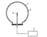
図12にこの種の放射線検出器に使用される従来の球形のガス電離箱の構成例を示す。図12においてガス電離箱1には検出ガス2が封入され、ガス電離箱1内に設けられた中心電極3からの出力電流は微少電流測定回路4によって測定される。
【0004】
【発明が解決しようとする課題】
ガス電離箱1から得られる出力信号は小さいため、バックグランドレベルにおいても測定可能な電流が得られるように設計すると、事故時に想定される高レベルγ線の照射時に電荷収集が飽和してしまう恐れがあるためガス電離箱1の測定ダイナミックレンジを広げる必要があった。
【0005】
また、ガス電離箱1では軽量であること、および処理が不要であることから検出器容器の材料としてアルミニウムが使用されることが多い。しかしながらアルミニウムはα線を出す放射性同位元素を比較的多く含むことからバックグランドレベルに匹敵する電離電流が生じてしまう。このためα線バックグランドを低減することが必要であった。
【0006】
本発明は、以上の課題を解決し、測定ダイナミックレンジが広く、α線バックグランドが低いガス電離箱を使用した放射線検出装置を提供することを目的とする。
【0007】
【課題を解決するための手段】
上記目的を達成するために請求項1に記載の放射線検出装置の発明は、検出ガスを封入した導電性容器と、導電性容器から電気的に絶縁されながら導電性容器を気密に貫通して導電容器内に設けられた電極支柱部と、電極支柱部の先端に位置し電極支柱部から絶縁されながら電極支柱部の先端部を覆う電極末端部と、電極支柱部と電極末端部とに接続された電離電流測定回路とからなることを特徴とする。
【0008】
この発明によれば、ガス電離箱からの信号を電極支柱部からと電極末端部とから分けて測定し、同一検出器内の信号から線量直線性の良い部分を抜き出して測定する。
【0009】
請求項2に記載の放射線検出装置の発明は、検出ガスを封入した導電性容器と、導電性容器から電気的に絶縁されながら導電性容器を気密に貫通して導電容器内に設けられた筒状の電極支柱部と、電極支柱部の先端に位置し電極支柱部から絶縁されながら電極支柱部の先端部を覆う電極末端部と、電極支柱部の筒内を通って電極末端部と電気的に接続され導電性容器を貫通する電流導入端子と、電極支柱部と電極末端部とに接続された電離電流測定回路とからなることを特徴とする。
この発明によれば、電極末端部からの信号への電界集中を防ぎ、線量直線性を高線量まで延ばす。
【0010】
請求項3に記載の放射線検出装置の発明は、検出ガスを封入した導電性容器と、導電性容器から電気的に絶縁されながら導電性容器を気密に貫通して導電容器内に設けられた電極支柱部と、電極支柱部の先端に位置し電極支柱部から絶縁されながら電極支柱部の先端部を覆う電極末端部と、電極支柱部と電極末端部とに各々接続された複数の電離電流測定回路と、複数の電離電流測定回路に接続された電離電流比較回路と、複数の電離電流測定回路に接続された信号切替補正回路とからなることを特徴とする。
【0011】
この発明によれば、第1の電離電流測定回路と第2の電離電流測定回路との出力を比較することにより、電極末端部における電流の飽和度が分かり、その情報を用いて信号切替補正回路において、第1の電離電流測定回路からの信号を使うのか、第2の電離電流測定回路からの信号を使うのか、第1の電離電流測定回路と第2の電離電流測定回路との出力に重み付けをして加え合わせたものを使うのかを選択する。
【0012】
請求項4に記載の放射線検出装置の発明は検出ガスを封入した導電性容器と、導電性容器から電気的に絶縁されながら導電性容器を気密に貫通して導電容器内に設けられた筒状の電極支柱部と、電極支柱部の先端に位置し電極支柱部から絶縁されながら電極支柱部の先端部を覆う電極末端部と、電極支柱部の筒内を通って電極末端部と電気的に接続され導電性容器を貫通する電流導入端子と、電極支柱部と電極末端部とに各々接続された複数の電離電流測定回路と、複数の電離電流測定回路に接続された電離電流比較回路と、複数の電離電流測定回路に接続された信号切替補正回路とからなることを特徴とする。
【0013】
この発明によれば、第1の電離電流測定回路と第2の電離電流測定回路との出力を比較することにより、電極末端部における電流の飽和度が分かり、その情報を用いて信号切替補正回路において、第1の電離電流測定回路からの信号を使うのか、第2の電離電流測定回路からの信号を使うのか、第1の電離電流測定回路と第2の電離電流測定回路との出力に重み付けをして加え合わせたものを使うのかを選択する。
【0014】
請求項5に記載の放射線検出装置の発明は、請求項1乃至4のいずれかに記載の放射線検出装置において、電極末端部が電極支柱部よりおきな曲率半径を有することを特徴とする。
この発明によれば、電極末端部への泳動電子の集中を緩和し、高線量照射時の飽和特性が改善され、広いダイナミックレンジにわたって直線性を保つ。
【0015】
請求項6に記載の放射線検出装置の発明は、検出ガスを封入した導電性容器と、導電性容器から電気的に絶縁されながら導電性容器を気密に貫通して導電性容器内に設けられた電極支柱部と、電極支柱部の先端に位置し電極支柱部と電気的に一体となり電極表面の電界強度が電極支柱部と同程度になる曲率半径を有した電極末端部と、電極支柱部と電極末端部とに接続された電離電流測定回路とからなることを特徴とする。
この発明によれば、電極末端部への泳動電子の集中を緩和し、高線量照射時の飽和特性を改善する。
【0016】
請求項7に記載の放射線検出装置の発明は、請求項1乃至6のいずれかに記載の放射線検出装置において、検出ガスを封入した導電性容器内にガス吸着材を設けたことを特徴とする。
【0017】
この発明によれば、検出ガス中の不純物が少なくなり、泳動電子の捕獲が減り、電荷収集率の飽和特性を改善し、照射線量に対するダイナミックレンジを拡大する。
【0018】
請求項8に記載の放射線検出装置の発明は、不活性ガスを主成分とする検出ガスを封入した導電性容器と、導電性容器から電気的に絶縁されながら導電性容器を気密に貫通して導電性容器内に設けられた電極と、導電性容器内の光を検出する光検出器と、光検出器の出力信号から放射線量を測定する処理回路とからなることを特徴とする。
この発明によれば、電極に達する前に再結合した電子はシンチレーション光として光検出器18により検出する。
【0019】
【発明の実施の形態】
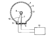
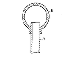
以下本発明の実施の形態について図面を参照して説明する。図1は本発明の第1の実施の形態を示す図で、検出ガス2を封入したガス電離箱1の導電性容器5から絶縁板6によって電気的に絶縁された中心電極の電極支柱部7が導電性容器5を気密に貫通して導電性容器5のほぼ中心部まで突き出して設けられている。電極支柱部7の先端には丸いキャップ状の電極末端部8があり電極支柱部7から絶縁されながら電極支柱部7の先端部を覆っている。電極末端部8は導電性容器5を貫通する電流導入端子9とリード線10を介して電気的に接続され、電極支柱部7と電極末端部8とはそれぞれ電離電流測定回路11に接続されている。電極末端部8の外側は球形で、内側は円柱状の電極支柱部7が差し込めるような穴が明けられた構造と成っている。
【0020】
このような構成の本発明の第1の実施の形態による放射線検出装置であると、導電性容器5内で発生した電荷は、導電性容器5と電極支柱部7、あるいは電極末端部8との間に加えられた電気力線に沿って泳動する。一方電気力線は電極支柱部7より電極末端部8に集中する。そのため泳動する電子は電極末端部8に多く集まることになる。電子親和性の不純物ガスが検出ガス2に含まれると泳動電子を捕獲して負イオンとなりやすい。そうすると泳動速度が1000分の1程度に遅くなり、見かけ上電極周辺に空間電荷層として蓄積する。この空間電荷層は照射線量が大きくなるとともに大きくなり、電極近傍の電界を小さくすることになり、泳動電子の捕獲、再結合を促進する。従って電極支柱部7に集められる電荷量は電極末端部8に集められる電荷量より飽和特性が良く、より高い照射線量に対してまで照射線量に対する出力電流の直線性が確保される。電極支柱部7に集められた電荷は、電離電流測定回路11に入力され電流量が測定される。電極末端部8に集められた電荷は、電流導入端子9を通して、電離電流測定回路11に入力され電流量が測定される。そのため電極支柱部7からの電離電流値は電極末端部8からの電離電流値より飽和特性が良く、より高い照射線量に対してまで照射線量に対する出力電流の直線性が確保されることになる。
【0021】
このようにガス電離箱1からの信号を電極支柱部7からと電極末端部8とから分けて測定することで、同一検出器内の信号から線量直線性の良い部分を抜き出すことができ、測定のダイナミックレンジを拡大することができる。
【0022】
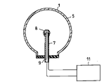
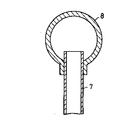
次に本発明の第2の実施の形態について図2を参照して説明する。図2において図1と同一部分は同一の符号を付し、詳細な説明は省略する。図2において、電極支柱部7を円筒状に形成し、電極末端部8に接続される電流導入端子9を電極支柱部7の先端開口部から円筒内部を通して電極支柱部7とは絶縁紙ながら導電性容器5の外部に引き出している。
【0023】
このような構成の本発明の第2の実施の形態による放射線検出装置であると、電極末端部8からの信号への電界の集中がないため、電極支柱部7でより高線量まで電荷収集効率が下がらず、飽和特性が改善され、照射線量に対する直線性が高線量にまで伸び、直線性が改善される。
【0024】
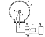
次に本発明の第3の実施の形態について図3を参照して説明する。図3において図1と同一部分は同一の符号を付し、詳細な説明は省略する。図3において、第1、第2の実施の形態で示す電離電流測定回路11の代わりに電極支柱部7からの電離電流を測定する第1の電離電流測定回路12と、電極末端部8からの電離電流を測定する第2の電離電流測定回路13と、第1の電離電流測定回路12の出力と第2の電離電流測定回路13の出力とを比較する電離電流比較回路14とを設け、さらにそれらに接続された信号切替補正回路15とを設ける。信号切替補正回路15の内部には信号切替補正回路15の出力として、第1の電離電流測定回路12からの信号を使うのか、第2の電離電流測定回路13からの信号を使うのか、または第1の電離電流測定回路12と第2の電離電流測定回路13との出力に重み付けをして加え合わせたものを使うのかを選択する選択回路が含まれている。
【0025】
このような構成の本発明の第3の実施の形態による放射線検出装置であると、第1の電離電流測定回路12と第2の電離電流測定回路13との出力を比較することにより、電極末端部8における電流の飽和度が分かる。その情報を用いて信号切替補正回路15において、第1の電離電流測定回路12からの信号を使うのか、第2の電離電流測定回路13からの信号を使うのか、第1の電離電流測定回路12と第2の電離電流測定回路13との出力に重み付けをして加え合わせたものを使うのかが選択される。これにより、放射線検出装置としての1個の出力について電離電流信号出力が広いダイナミックレンジにわたって直線性を保つことが出来る。
【0026】
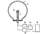
次に本発明の第4の実施の形態について図4を参照して説明する。図4において図3と同一部分は同一の符号を付し、詳細な説明は省略する。図4においては、図2に示す電極構造に対して図3に示す電離電流比較回路14と信号切替補正回路15とを設けた例で作用効果は図3に示す第三の実施の形態と同様の作用効果が得られる。
【0027】
次に本発明の第5の実施の形態について図5を参照して説明する。図5において、電極末端部8の曲率半径を電極支柱部7の半径より大きくする。
このような構成の本発明の第5の実施の形態による放射線検出装置であると、電極末端部8への泳動電子の集中が緩和されるため、高線量照射時の飽和特性が改善され、さらに広いダイナミックレンジにわたって直線性を保つことができる。
【0028】
次に本発明の第6の実施の形態について図6を参照して説明する。図6において、電極表面近傍での電界強度が電極末端部8と電極支柱部7とで同程度になるよう、電極末端部8の曲率半径を大きくする。そして電極末端部8は電極支柱部7に電気的に接続するかあるいは一体のものとして構成し、その出力を電離電流測定回路に接続する。
【0029】
このような構成の本発明の第6の実施の形態による放射線検出装置であると、電極末端部8への泳動電子の集中が緩和され、高線量照射時の飽和特性が改善されるうえに、電離電流測定回路が電離箱1個につき1系統が必要されるだけとなり、より簡素化した測定システムとなる。
【0030】
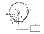
次に本発明の第7の実施の形態について図7を参照して説明する。図7において図1と同一部分は同一の符号を付し、詳細な説明は省略する。図7において、検出ガス2を封入した導電性容器5から電気的に絶縁された電極支柱部7が導電性容器5を気密に貫通して導電性容器5のほぼ中心部まで突き出して設けられている。電極支柱部7の先端には丸いキャップ状の電極末端部8があって電極支柱部7から絶縁されながら電極支柱部7の先端部を覆っている。電極末端部8は導電性容器5を貫通する電流導入端子9とリード線10を介して電気的に接続され、電極支柱部7と電極末端部8とはそれぞれ電離電流測定回路11に接続されている。電極末端部8の外側は球形で、内側は円柱状の電極支柱部7が差し込めるような穴が明けられた構造と成っている。
【0031】
このようなガス電離箱1において酸素分子および窒素酸化物を吸着する能力を持ったガス吸着剤16を導電性容器5内に設けている。ガス吸着剤16の形状および導電性容器5内での取り付け位置は適宜任意である。
【0032】
このような構成の本発明の第7の実施の形態による放射線検出装置であると、泳動電子は検出ガス2中に含まれる酸素分子や窒素酸化物のように電子親和性の大きい不純物に捕獲されることで空間電荷層を形成するようになる。導電性容器5内で発生した電荷は、導電性容器5と電極支柱部7あるいは電極末端部8との間に加えられた電気力線に沿って泳動する。一方電気力線は電極支柱部7より電極末端部8に集中する。そのため泳動する電子は電極末端部8に多く集まることになる。電子親和性の不純物ガスが検出ガス2中に含まれると泳動電子を捕獲して負イオンとなりやすい。そうすると泳動速度が1000分の1程度に遅くなり、見かけ上電極周辺に空間電荷層として蓄積する。この空間電荷層は照射線量が大きくなるとともに大きくなり、電極近傍の電界を小さくすることになり、泳動電子の捕獲、再結合を促進する。従って電極支柱部7に集められる電荷量は電極末端部8に集められる電荷量より飽和特性が良く、より高い照射線量に対してまで照射線量に対する出力電流の直線性が確保される。電極支柱部7に集められた電荷は、電離電流測定回路11に入力され電流量が測定される。電極末端部8に集められた電荷は、電流導入端子9を通して、電離電流測定回路11に入力され電流量が測定される。そのため電極支柱部7からの電離電流値は電極末端部8からの電離電流値より飽和特性が良く、より高い照射線量に対してまで照射線量に対する出力電流の直線性が確保されることになる。
【0033】
このように、検出ガス2中の不純物が少なくなることで泳動電子の捕獲が減り、電荷収集率の飽和特性が改善され、照射線量に対するダイナミックレンジを拡大することができる。
【0034】
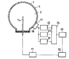
次に本発明の第8の実施の形態について図8を参照して説明する。図8において図1と同一部分は同一の符号を付し、詳細な説明は省略する。図8において、不活性ガスを主成分とした検出ガス2を封入した導電性容器5から絶縁蓋6によって電気的に絶縁された電極7aが導電性容器5を気密に貫通して導電性容器5のほぼ中心部まで突き出して設けられている。導電性容器5に透明な窓17を気密に設け、その窓17の外側に光検出器18を取り付ける。窓17の材質は検出ガス2のシンチレーション光を透過する材質とし、真空紫外光の場合のように透過する材質が入手し難い場合は窓17の導電性容器5内側にサイリチルサンメチルやPOPOPのような波長変換物質19を塗布する。光検出器18の出力は一般的な微少電流測定回路またはパルス計数回路20に入力される。また、導電性容器5内の電極7aからの信号は電離電流測定回路11に入力される。さらに一般的な微少電流測定回路またはパルス計数回路20と電離電流測定回路11との出力は光検出系の信号に基づいて電離電流測定回路11の出力を補正する出力補正回路21に入力される。
【0035】
このような構成の本発明の第8の実施の形態による放射線検出装置であると、検出ガス2のシンチレーション光は電離に至るまでエネルギーを付与されなかった検出ガス2の分子、あるいは一旦は電離したものの再結合した検出ガス2のイオンによって発生する。従って電極7a近傍の空間電荷層により電子泳動が滞留すると、滞留した電子は電極7aに達する前に再結合する確率が大きくなる。従来の検出器では電極に達しない電子を測定することはできなかったが、本発明による検出装置においては再結合した電子はシンチレーション光として光検出器18により検出可能になる。電極7aにより測定される電離電流をI、シンチレーション光を測定した光検出器18からの出力電流等をS、放射線により付与されたエネルギーをEとすると、補正係数をαと換算係数βを用いて、E=β(I+αS)と表されることが実験的に示されているので出力補正回路21においてE=β(I+αS)と同様の補正をすることにより、電荷収集の飽和を補正することが可能になり、再結合電子が線量測定に寄与することで、電荷収集率の飽和特性を補正により改善することができ、照射線量に対するダイナミックレンジを拡大することができる。
【0036】
次に本発明の第9の実施の形態について図9を参照して説明する。図9において図8と同一部分は同一の符号を付し、詳細な説明は省略する。図9において、光検出器18の出力は電流測定回路22、パルス波形弁別回路23およびパルス計数回路24を介してγ線識別計数回路25に接続される。電極および電離電流測定回路は設けない。
【0037】
このような構成の本発明の第9の実施の形態による放射線検出装置であると、γ線に起因する2次電子と検出ガス2との相互作用によるものに比べて、α線や宇宙線と検出ガス2との相互作用によるものは、検出ガス2のシンチレーション光のパルス減衰時間が短い。そこでパルス波形弁別回路23で2次電子によるシンチレーションとα線、宇宙線によるシンチレーションを識別する。一方パルス計数回路24では放射線の種別を区別せずに計数している。そこでγ線識別計数回路25に放射線種類と計数に関する情報を供給することで、γ線識別計数回路25はガンマ線のみの計数を行うことが可能になる。
【0038】
したがって、このような構成の放射線検出装置であると、γ線による信号のみを識別して線量測定を行うことで、導電性容器5に起因するα線バックグランド等のバックグランドの影響を排除し低バックグランドの測定が行える。
【0039】
次に本発明の第10の実施の形態について図10を参照して説明する。図10において図8と同一部分は同一の符号を付し、詳細な説明は省略する。図10において、導電性容器5を気密に貫通して導電性容器5のほぼ中心部まで突き出して設けられた電極7aが電離電流測定回路11、パルス計数回路24とパルス電荷量測定回路26に接続される。パルス電荷量測定回路26の出力は、パルス計数回路24の出力と共に電荷量、電流換算回路27に入力される。電荷量、電流換算回路27の出力は、電離電流測定回路11の出力とともに出力電流補正回路28に入力され、電離電流測定回路11の出力から電荷量、電流換算回路27の出力が差し引かれる。
【0040】
このような構成の本発明の第10の実施の形態による放射線検出装置であると、第9の実施の形態で説明したしたパルス計数により、α線等パルス幅が比較的短い信号の発生電荷量および発生頻度を測定できる。従って電荷量、電流変換回路27の出力は、主にα線に起因するバックグランド電流となる。従って出力電流補正回路28において電離電流測定回路11の出力から電荷量、電流換算回路27の出力を差し引くことで、当該バックグランド電流の補正が行え、導電性容器5に起因するα線バックグランド等のバックグランドの影響を排除し低バックグランドの測定が行える。
【0041】
次に本発明の第11の実施の形態について図11を参照して説明する。図11において図8と同一部分は同一の符号を付し、詳細な説明は省略する。図11において、光検出器18の出力は電流測定回路22、パルス波形弁別回路23およびパルス計数回路24を介しγ線識別計数回路25に入力される。電離電流測定回路11については、導電性容器5を気密に貫通して導電性容器5のほぼ中心部まで突き出して設けられた電極7aと接続されている。さらに、光検出器18の信号に基づいてγ線以外の放射線による発生電荷量を計算する電流計算回路29と、電流計算回路29の出力と電離電流測定回路11の出力とを用いて電離電流測定回路11の出力を補正する出力補正回路30を設ける。
【0042】
このような構成の本発明の第11の実施の形態による放射線検出装置であると、第9の実施の形態で説明したγ線識別によりγ線以外の放射線による計数値が求まる。この結果に基づき電流計算回路29において、γ線以外の放射線の入射によって発生する平均的な電流値を計算する。得られた電流値を出力補正回路30に入力し、電離電流測定回路11の出力から差し引くことにより、γ線のみの寄与による電離電流値を求めることができ、γ線による信号のみを識別して線量測定を行う事で、導電性容器5に起因するα線バックグランド等のバックグランドの影響を排除し低バックグランドの測定が行える。
【0043】
【発明の効果】
以上説明したように本発明によれば、検出ガスを封入した導電性容器と、導電性容器から電気的に絶縁されながら導電性容器を気密に貫通して導電容器内に設けられた電極支柱部と、電極支柱部の先端に位置し電極支柱部から絶縁されながら電極支柱部の先端部を覆う電極末端部と、電極支柱部と電極末端部とに接続された電離電流測定回路とから構成したので、測定ダイナミックレンジが広く、かつα線バックグランドが低い放射線検出装置を提供することができる。
【図面の簡単な説明】
【図1】本発明の第1の実施の形態による放射線検出装置を示すブロック構成図。
【図2】本発明の第2の実施の形態による放射線検出装置を示すブロック構成図。
【図3】本発明の第3の実施の形態による放射線検出装置を示すブロック構成図。
【図4】本発明の第4の実施の形態による放射線検出装置を示すブロック構成図。
【図5】本発明の第5の実施の形態による放射線検出装置を示すブロック構成図。
【図6】本発明の第6の実施の形態による放射線検出装置を示すブロック構成図。
【図7】本発明の第7の実施の形態による放射線検出装置を示すブロック構成図。
【図8】本発明の第8の実施の形態による放射線検出装置を示すブロック構成図。
【図9】本発明の第9の実施の形態による放射線検出装置を示すブロック構成図。
【図10】本発明の第10の実施の形態による放射線検出装置を示すブロック構成図。
【図11】本発明の第11の実施の形態による放射線検出装置を示すブロック構成図。
【図12】従来の放射線検出装置を示すブロック構成図。
【符号の説明】
1…ガス電離箱、2…検出ガス、5…導電性容器、7…電極支柱部、7a…電極、8…電極末端部、9…電流導入端子、11…電離電流測定回路、12…第1の電離電流測定回路、13…第2の電離電流測定回路、14…電離電流比較回路、15…信号切替補正回路、16…ガス吸着材、17…窓、18…光検出器、19…波長変換物質、20…微少電流測定回路またはパルス計数回路、21…出力補正回路、22…電流測定回路、23…パルス波形弁別回路、24…パルス計数回路、25…γ線識別計数回路、26…パルス電荷量測定回路、27…電荷量、電流換算回路、28…出力電流補正回路、29…電流計算回路、30…出力補正回路。[0001]
TECHNICAL FIELD OF THE INVENTION
The present invention relates to a radiation detection apparatus for measuring gamma rays using a gas ionization chamber used in, for example, a nuclear facility.
[0002]
[Prior art]
Conventionally, gamma-ray detectors have been installed in areas and regions where nuclear facilities such as nuclear power plants exist to evaluate external exposure of the general public, and gamma rays from background levels to high levels at the time of accidents have been installed. Is constantly monitored. The γ-ray detector used must be able to measure continuously from a background level to a high radiation level at the time of an accident over a wide dynamic range. Furthermore, since it is used for evaluation of human external exposure, the energy characteristics of the response become severe, and since the measurement target is environmental γ-ray, it is required that the report characteristics be uniform in the 4π direction. For this reason, conventionally, a center electrode is provided in a container in which an inert gas such as argon gas is sealed, and when radiation enters the container, the gas is ionized to generate ions, and the current flowing from the center electrode is detected to detect radiation. A spherical gas ionization chamber is used to measure intensity, dose and energy.
[0003]
FIG. 12 shows a configuration example of a conventional spherical gas ionization chamber used in this type of radiation detector. In FIG. 12, a
[0004]
[Problems to be solved by the invention]
Since the output signal obtained from the
[0005]
In addition, since the
[0006]
An object of the present invention is to solve the above problems and to provide a radiation detection apparatus using a gas ionization chamber having a wide measurement dynamic range and a low α-ray background.
[0007]
[Means for Solving the Problems]
In order to achieve the above object, the invention of the radiation detection apparatus according to
[0008]
According to the present invention, the signal from the gas ionization chamber is measured separately from the electrode support portion and the electrode end portion, and a portion having good dose linearity is extracted and measured from the signal in the same detector.
[0009]
The invention of the radiation detection apparatus according to
According to the present invention, the electric field concentration on the signal from the electrode end portion is prevented, and the dose linearity is extended to a high dose.
[0010]
According to a third aspect of the present invention, there is provided a radiation detecting apparatus comprising: a conductive container in which a detection gas is sealed; and an electrode provided in the conductive container through an airtight passage through the conductive container while being electrically insulated from the conductive container. A support portion, an electrode end portion located at the tip of the electrode support portion and covering the end portion of the electrode support portion while being insulated from the electrode support portion, and a plurality of ionization current measurements respectively connected to the electrode support portion and the electrode end portion A circuit, an ionization current comparison circuit connected to the plurality of ionization current measurement circuits, and a signal switching correction circuit connected to the plurality of ionization current measurement circuits.
[0011]
According to the present invention, by comparing the output of the first ionization current measurement circuit and the output of the second ionization current measurement circuit, the saturation of the current at the electrode end can be determined, and the signal switching correction circuit is used by using the information. , Weighting the outputs of the first and second ionization current measurement circuits, whether to use the signal from the first ionization current measurement circuit or the signal from the second ionization current measurement circuit And choose whether to use the combined one.
[0012]
According to a fourth aspect of the present invention, there is provided a radiation detecting apparatus comprising: a conductive container in which a detection gas is sealed; and a tubular member provided in the conductive container through the conductive container in an airtight manner while being electrically insulated from the conductive container. An electrode support portion, an electrode end portion located at the tip of the electrode support portion and covering the tip end portion of the electrode support portion while being insulated from the electrode support portion, and an electrode end portion electrically passing through the cylinder of the electrode support portion. A current introduction terminal that is connected and penetrates the conductive container, a plurality of ionization current measurement circuits respectively connected to the electrode support and the electrode end, and an ionization current comparison circuit connected to the plurality of ionization current measurement circuits, And a signal switching correction circuit connected to the plurality of ionization current measurement circuits.
[0013]
According to the present invention, by comparing the output of the first ionization current measurement circuit and the output of the second ionization current measurement circuit, the saturation of the current at the electrode end can be determined, and the signal switching correction circuit is used by using the information. , Weighting the outputs of the first and second ionization current measurement circuits, whether to use the signal from the first ionization current measurement circuit or the signal from the second ionization current measurement circuit And choose whether to use the combined one.
[0014]
According to a fifth aspect of the present invention, in the radiation detecting apparatus according to any one of the first to fourth aspects, the terminal end of the electrode has a curvature radius different from that of the electrode support.
According to the present invention, the concentration of the migrating electrons to the electrode terminal portion is reduced, the saturation characteristics at the time of high dose irradiation are improved, and the linearity is maintained over a wide dynamic range.
[0015]
The radiation detecting apparatus according to
According to the present invention, the concentration of the migrating electrons at the terminal of the electrode is reduced, and the saturation characteristic at the time of high dose irradiation is improved.
[0016]
According to a seventh aspect of the present invention, in the radiation detecting apparatus according to any one of the first to sixth aspects, a gas adsorbent is provided in a conductive container in which a detection gas is sealed. .
[0017]
According to the present invention, impurities in the detection gas are reduced, capture of migrating electrons is reduced, the saturation characteristic of the charge collection rate is improved, and the dynamic range with respect to the irradiation dose is expanded.
[0018]
The radiation detecting apparatus according to the eighth aspect of the present invention includes a conductive container in which a detection gas containing an inert gas as a main component is sealed, and a conductive container which is electrically insulated from the conductive container and hermetically penetrates the conductive container. It is characterized by comprising an electrode provided in a conductive container, a photodetector for detecting light in the conductive container, and a processing circuit for measuring a radiation dose from an output signal of the photodetector.
According to the present invention, electrons recombined before reaching the electrodes are detected by the
[0019]
BEST MODE FOR CARRYING OUT THE INVENTION
Hereinafter, embodiments of the present invention will be described with reference to the drawings. FIG. 1 is a view showing a first embodiment of the present invention, in which an
[0020]
In the radiation detecting apparatus according to the first embodiment of the present invention having such a configuration, the electric charge generated in the
[0021]
By measuring the signal from the
[0022]
Next, a second embodiment of the present invention will be described with reference to FIG. In FIG. 2, the same parts as those in FIG. In FIG. 2, the
[0023]
In the radiation detecting apparatus according to the second embodiment of the present invention having such a configuration, since the electric field is not concentrated on the signal from the
[0024]
Next, a third embodiment of the present invention will be described with reference to FIG. In FIG. 3, the same portions as those in FIG. In FIG. 3, instead of the ionization
[0025]
With the radiation detecting apparatus according to the third embodiment of the present invention having such a configuration, by comparing the outputs of the first ionization
[0026]
Next, a fourth embodiment of the present invention will be described with reference to FIG. In FIG. 4, the same parts as those in FIG. FIG. 4 shows an example in which the ionization
[0027]
Next, a fifth embodiment of the present invention will be described with reference to FIG. In FIG. 5, the radius of curvature of the
In the radiation detecting apparatus according to the fifth embodiment of the present invention having such a configuration, the concentration of the migrating electrons to the
[0028]
Next, a sixth embodiment of the present invention will be described with reference to FIG. In FIG. 6, the radius of curvature of the
[0029]
With the radiation detecting apparatus according to the sixth embodiment of the present invention having such a configuration, the concentration of the migrating electrons to the
[0030]
Next, a seventh embodiment of the present invention will be described with reference to FIG. In FIG. 7, the same parts as those in FIG. In FIG. 7, an
[0031]
In such a
[0032]
In the radiation detection apparatus according to the seventh embodiment of the present invention having such a configuration, the migrating electrons are captured by impurities having a high electron affinity such as oxygen molecules and nitrogen oxides contained in the
[0033]
As described above, the trapping of the migrating electrons is reduced due to the reduced impurities in the
[0034]
Next, an eighth embodiment of the present invention will be described with reference to FIG. In FIG. 8, the same parts as those in FIG. In FIG. 8, an
[0035]
In the radiation detecting apparatus according to the eighth embodiment of the present invention having such a configuration, the scintillation light of the
[0036]
Next, a ninth embodiment of the present invention will be described with reference to FIG. In FIG. 9, the same parts as those in FIG. In FIG. 9, the output of the
[0037]
With the radiation detecting apparatus according to the ninth embodiment of the present invention having such a configuration, the radiation detecting apparatus according to the ninth embodiment of the present invention has a higher sensitivity to α-rays and cosmic rays than those due to the interaction between secondary electrons caused by γ-rays and the
[0038]
Therefore, according to the radiation detecting apparatus having such a configuration, the influence of the background such as the α-ray background caused by the
[0039]
Next, a tenth embodiment of the present invention will be described with reference to FIG. In FIG. 10, the same parts as those in FIG. In FIG. 10, an
[0040]
With the radiation detecting apparatus according to the tenth embodiment of the present invention having such a configuration, the pulse count described in the ninth embodiment makes it possible to calculate the amount of generated electric charge of a signal having a relatively short pulse width such as α-ray. And the frequency of occurrence can be measured. Accordingly, the charge amount and the output of the
[0041]
Next, an eleventh embodiment of the present invention will be described with reference to FIG. In FIG. 11, the same portions as those in FIG. 8 are denoted by the same reference numerals, and detailed description will be omitted. In FIG. 11, the output of the
[0042]
With the radiation detecting apparatus according to the eleventh embodiment of the present invention having such a configuration, a count value due to radiation other than γ-rays is obtained by γ-ray identification described in the ninth embodiment. Based on the result, the
[0043]
【The invention's effect】
As described above, according to the present invention, a conductive container in which a detection gas is sealed, and an electrode support portion provided in the conductive container through the conductive container in a gas-tight manner while being electrically insulated from the conductive container And an electrode end located at the tip of the electrode support and covering the tip of the electrode support while being insulated from the electrode support, and an ionization current measuring circuit connected to the electrode support and the electrode end. Therefore, it is possible to provide a radiation detection device having a wide measurement dynamic range and a low α-ray background.
[Brief description of the drawings]
FIG. 1 is a block diagram showing a radiation detecting apparatus according to a first embodiment of the present invention.
FIG. 2 is a block diagram showing a radiation detection apparatus according to a second embodiment of the present invention.
FIG. 3 is a block diagram showing a radiation detecting apparatus according to a third embodiment of the present invention.
FIG. 4 is a block diagram showing a radiation detecting apparatus according to a fourth embodiment of the present invention.
FIG. 5 is a block diagram showing a radiation detecting apparatus according to a fifth embodiment of the present invention.
FIG. 6 is a block diagram showing a radiation detecting apparatus according to a sixth embodiment of the present invention.
FIG. 7 is a block diagram showing a radiation detecting apparatus according to a seventh embodiment of the present invention.
FIG. 8 is a block diagram showing a radiation detecting apparatus according to an eighth embodiment of the present invention.
FIG. 9 is a block diagram showing a radiation detection apparatus according to a ninth embodiment of the present invention.
FIG. 10 is a block diagram showing a radiation detecting apparatus according to a tenth embodiment of the present invention.
FIG. 11 is a block diagram showing a radiation detecting apparatus according to an eleventh embodiment of the present invention.
FIG. 12 is a block diagram showing a conventional radiation detection apparatus.
[Explanation of symbols]
DESCRIPTION OF
Claims (8)
Priority Applications (1)
| Application Number | Priority Date | Filing Date | Title |
|---|---|---|---|
| JP2002172364A JP3984110B2 (en) | 2002-06-13 | 2002-06-13 | Radiation detector |
Applications Claiming Priority (1)
| Application Number | Priority Date | Filing Date | Title |
|---|---|---|---|
| JP2002172364A JP3984110B2 (en) | 2002-06-13 | 2002-06-13 | Radiation detector |
Publications (2)
| Publication Number | Publication Date |
|---|---|
| JP2004020249A true JP2004020249A (en) | 2004-01-22 |
| JP3984110B2 JP3984110B2 (en) | 2007-10-03 |
Family
ID=31171952
Family Applications (1)
| Application Number | Title | Priority Date | Filing Date |
|---|---|---|---|
| JP2002172364A Expired - Lifetime JP3984110B2 (en) | 2002-06-13 | 2002-06-13 | Radiation detector |
Country Status (1)
| Country | Link |
|---|---|
| JP (1) | JP3984110B2 (en) |
Cited By (7)
| Publication number | Priority date | Publication date | Assignee | Title |
|---|---|---|---|---|
| JP2007205769A (en) * | 2006-01-31 | 2007-08-16 | Toshiba Corp | Radiation detector |
| WO2011135682A1 (en) * | 2010-04-27 | 2011-11-03 | 株式会社リガク | Gas-filled proportional counter |
| CN103472476A (en) * | 2013-09-16 | 2013-12-25 | 中国船舶重工集团公司第七一九研究所 | Detector for monitoring environmental radiation dose rate |
| EP3086139A1 (en) * | 2015-04-24 | 2016-10-26 | Commissariat A L'energie Atomique Et Aux Energies Alternatives | Holding rod of a spherical detection device |
| CN111696845A (en) * | 2019-03-15 | 2020-09-22 | 浜松光子学株式会社 | Electron tube |
| WO2022071549A1 (en) * | 2020-10-01 | 2022-04-07 | 大日本印刷株式会社 | Detection device |
| WO2023095576A1 (en) * | 2021-11-25 | 2023-06-01 | 学校法人東京理科大学 | Radiation detection device |
-
2002
- 2002-06-13 JP JP2002172364A patent/JP3984110B2/en not_active Expired - Lifetime
Cited By (12)
| Publication number | Priority date | Publication date | Assignee | Title |
|---|---|---|---|---|
| JP2007205769A (en) * | 2006-01-31 | 2007-08-16 | Toshiba Corp | Radiation detector |
| WO2011135682A1 (en) * | 2010-04-27 | 2011-11-03 | 株式会社リガク | Gas-filled proportional counter |
| CN103472476A (en) * | 2013-09-16 | 2013-12-25 | 中国船舶重工集团公司第七一九研究所 | Detector for monitoring environmental radiation dose rate |
| EP3086139A1 (en) * | 2015-04-24 | 2016-10-26 | Commissariat A L'energie Atomique Et Aux Energies Alternatives | Holding rod of a spherical detection device |
| FR3035516A1 (en) * | 2015-04-24 | 2016-10-28 | Commissariat Energie Atomique | CANE FOR HOLDING A SPHERICAL DETECTION DEVICE |
| CN111696845A (en) * | 2019-03-15 | 2020-09-22 | 浜松光子学株式会社 | Electron tube |
| WO2022071549A1 (en) * | 2020-10-01 | 2022-04-07 | 大日本印刷株式会社 | Detection device |
| JPWO2022071549A1 (en) * | 2020-10-01 | 2022-04-07 | ||
| JP7215639B2 (en) | 2020-10-01 | 2023-01-31 | 大日本印刷株式会社 | detector |
| JP2025061266A (en) * | 2020-10-01 | 2025-04-10 | 大日本印刷株式会社 | Detector |
| US12352908B2 (en) | 2020-10-01 | 2025-07-08 | Dai Nippon Printing Co., Ltd. | Detection device |
| WO2023095576A1 (en) * | 2021-11-25 | 2023-06-01 | 学校法人東京理科大学 | Radiation detection device |
Also Published As
| Publication number | Publication date |
|---|---|
| JP3984110B2 (en) | 2007-10-03 |
Similar Documents
| Publication | Publication Date | Title |
|---|---|---|
| US6333504B1 (en) | Semiconductor radiation detector with enhanced charge collection | |
| EP3014301B1 (en) | Semiconductor scintillation detector | |
| JP2010133879A (en) | Radiation measuring apparatus | |
| US4785168A (en) | Device for detecting and localizing neutral particles, and application thereof | |
| JPS5853470B2 (en) | Ionization chamber with grid | |
| Breskin et al. | On the low-pressure operation of multistep avalanche chambers | |
| CN117607241A (en) | An alpha particle ionization chamber and a method for reducing the background of radon and its progeny therein | |
| JP3984110B2 (en) | Radiation detector | |
| Bolotnikov et al. | Dual-anode high-pressure xenon cylindrical ionization chamber | |
| JP4499262B2 (en) | Ionization chamber type radiation detector and ionization chamber inspection method | |
| Charpak et al. | Development of new hole-type avalanche detectors and the first results of their applications | |
| JP4136301B2 (en) | Radioactive ion detector | |
| JP3151487B2 (en) | Radiation detection method | |
| US4179608A (en) | Right/left assignment in drift chambers and proportional multiwire chambers (PWC's) using induced signals | |
| Segui et al. | Characterization and first beam loss detection with one ESS-nBLM system detector | |
| Alfonsi et al. | Advances in fast multi-GEM based detector operation for high-rate charged-particle triggering | |
| JPH01100493A (en) | Nuclear fission type neutron detector | |
| Charpak | Some prospects with gaseous detectors | |
| JP3534456B2 (en) | Radiation measurement device | |
| CN114488269B (en) | A proportional counter | |
| Breskin et al. | The use of rise-time information in drift or proportional chambers for neutral radiation localization | |
| US6452190B1 (en) | Radiation detector provided with an absorption chamber and a plurality of avalanche chambers | |
| JP2007163399A (en) | Radiation discrimination detector | |
| Breskin et al. | A multistep parallax-free X-ray imaging counter | |
| SU824808A1 (en) | Multifilament device for detecting charged particles |
Legal Events
| Date | Code | Title | Description |
|---|---|---|---|
| A621 | Written request for application examination |
Free format text: JAPANESE INTERMEDIATE CODE: A621 Effective date: 20050404 |
|
| RD04 | Notification of resignation of power of attorney |
Free format text: JAPANESE INTERMEDIATE CODE: A7424 Effective date: 20060825 |
|
| RD02 | Notification of acceptance of power of attorney |
Free format text: JAPANESE INTERMEDIATE CODE: A7422 Effective date: 20070220 |
|
| A977 | Report on retrieval |
Free format text: JAPANESE INTERMEDIATE CODE: A971007 Effective date: 20070403 |
|
| A131 | Notification of reasons for refusal |
Free format text: JAPANESE INTERMEDIATE CODE: A131 Effective date: 20070410 |
|
| A521 | Written amendment |
Free format text: JAPANESE INTERMEDIATE CODE: A523 Effective date: 20070606 |
|
| TRDD | Decision of grant or rejection written | ||
| A01 | Written decision to grant a patent or to grant a registration (utility model) |
Free format text: JAPANESE INTERMEDIATE CODE: A01 Effective date: 20070703 |
|
| A61 | First payment of annual fees (during grant procedure) |
Free format text: JAPANESE INTERMEDIATE CODE: A61 Effective date: 20070705 |
|
| FPAY | Renewal fee payment (prs date is renewal date of database) |
Free format text: PAYMENT UNTIL: 20100713 Year of fee payment: 3 |
|
| FPAY | Renewal fee payment (prs date is renewal date of database) |
Year of fee payment: 3 Free format text: PAYMENT UNTIL: 20100713 |