JP2004019523A - Exhaust emission control device of internal combustion engine - Google Patents
Exhaust emission control device of internal combustion engine Download PDFInfo
- Publication number
- JP2004019523A JP2004019523A JP2002174467A JP2002174467A JP2004019523A JP 2004019523 A JP2004019523 A JP 2004019523A JP 2002174467 A JP2002174467 A JP 2002174467A JP 2002174467 A JP2002174467 A JP 2002174467A JP 2004019523 A JP2004019523 A JP 2004019523A
- Authority
- JP
- Japan
- Prior art keywords
- exhaust gas
- particulate filter
- internal combustion
- combustion engine
- amount
- Prior art date
- Legal status (The legal status is an assumption and is not a legal conclusion. Google has not performed a legal analysis and makes no representation as to the accuracy of the status listed.)
- Granted
Links
Images


Classifications
-
- F—MECHANICAL ENGINEERING; LIGHTING; HEATING; WEAPONS; BLASTING
- F01—MACHINES OR ENGINES IN GENERAL; ENGINE PLANTS IN GENERAL; STEAM ENGINES
- F01N—GAS-FLOW SILENCERS OR EXHAUST APPARATUS FOR MACHINES OR ENGINES IN GENERAL; GAS-FLOW SILENCERS OR EXHAUST APPARATUS FOR INTERNAL COMBUSTION ENGINES
- F01N9/00—Electrical control of exhaust gas treating apparatus
- F01N9/005—Electrical control of exhaust gas treating apparatus using models instead of sensors to determine operating characteristics of exhaust systems, e.g. calculating catalyst temperature instead of measuring it directly
-
- F—MECHANICAL ENGINEERING; LIGHTING; HEATING; WEAPONS; BLASTING
- F01—MACHINES OR ENGINES IN GENERAL; ENGINE PLANTS IN GENERAL; STEAM ENGINES
- F01N—GAS-FLOW SILENCERS OR EXHAUST APPARATUS FOR MACHINES OR ENGINES IN GENERAL; GAS-FLOW SILENCERS OR EXHAUST APPARATUS FOR INTERNAL COMBUSTION ENGINES
- F01N11/00—Monitoring or diagnostic devices for exhaust-gas treatment apparatus, e.g. for catalytic activity
- F01N11/002—Monitoring or diagnostic devices for exhaust-gas treatment apparatus, e.g. for catalytic activity the diagnostic devices measuring or estimating temperature or pressure in, or downstream of the exhaust apparatus
- F01N11/005—Monitoring or diagnostic devices for exhaust-gas treatment apparatus, e.g. for catalytic activity the diagnostic devices measuring or estimating temperature or pressure in, or downstream of the exhaust apparatus the temperature or pressure being estimated, e.g. by means of a theoretical model
-
- F—MECHANICAL ENGINEERING; LIGHTING; HEATING; WEAPONS; BLASTING
- F01—MACHINES OR ENGINES IN GENERAL; ENGINE PLANTS IN GENERAL; STEAM ENGINES
- F01N—GAS-FLOW SILENCERS OR EXHAUST APPARATUS FOR MACHINES OR ENGINES IN GENERAL; GAS-FLOW SILENCERS OR EXHAUST APPARATUS FOR INTERNAL COMBUSTION ENGINES
- F01N9/00—Electrical control of exhaust gas treating apparatus
- F01N9/002—Electrical control of exhaust gas treating apparatus of filter regeneration, e.g. detection of clogging
-
- F—MECHANICAL ENGINEERING; LIGHTING; HEATING; WEAPONS; BLASTING
- F02—COMBUSTION ENGINES; HOT-GAS OR COMBUSTION-PRODUCT ENGINE PLANTS
- F02D—CONTROLLING COMBUSTION ENGINES
- F02D41/00—Electrical control of supply of combustible mixture or its constituents
- F02D41/02—Circuit arrangements for generating control signals
- F02D41/021—Introducing corrections for particular conditions exterior to the engine
- F02D41/0235—Introducing corrections for particular conditions exterior to the engine in relation with the state of the exhaust gas treating apparatus
- F02D41/027—Introducing corrections for particular conditions exterior to the engine in relation with the state of the exhaust gas treating apparatus to purge or regenerate the exhaust gas treating apparatus
- F02D41/029—Introducing corrections for particular conditions exterior to the engine in relation with the state of the exhaust gas treating apparatus to purge or regenerate the exhaust gas treating apparatus the exhaust gas treating apparatus being a particulate filter
-
- F—MECHANICAL ENGINEERING; LIGHTING; HEATING; WEAPONS; BLASTING
- F02—COMBUSTION ENGINES; HOT-GAS OR COMBUSTION-PRODUCT ENGINE PLANTS
- F02D—CONTROLLING COMBUSTION ENGINES
- F02D41/00—Electrical control of supply of combustible mixture or its constituents
- F02D41/02—Circuit arrangements for generating control signals
- F02D41/14—Introducing closed-loop corrections
- F02D41/1438—Introducing closed-loop corrections using means for determining characteristics of the combustion gases; Sensors therefor
- F02D41/1444—Introducing closed-loop corrections using means for determining characteristics of the combustion gases; Sensors therefor characterised by the characteristics of the combustion gases
- F02D41/1448—Introducing closed-loop corrections using means for determining characteristics of the combustion gases; Sensors therefor characterised by the characteristics of the combustion gases the characteristics being an exhaust gas pressure
-
- F—MECHANICAL ENGINEERING; LIGHTING; HEATING; WEAPONS; BLASTING
- F01—MACHINES OR ENGINES IN GENERAL; ENGINE PLANTS IN GENERAL; STEAM ENGINES
- F01N—GAS-FLOW SILENCERS OR EXHAUST APPARATUS FOR MACHINES OR ENGINES IN GENERAL; GAS-FLOW SILENCERS OR EXHAUST APPARATUS FOR INTERNAL COMBUSTION ENGINES
- F01N2330/00—Structure of catalyst support or particle filter
- F01N2330/06—Ceramic, e.g. monoliths
-
- F—MECHANICAL ENGINEERING; LIGHTING; HEATING; WEAPONS; BLASTING
- F01—MACHINES OR ENGINES IN GENERAL; ENGINE PLANTS IN GENERAL; STEAM ENGINES
- F01N—GAS-FLOW SILENCERS OR EXHAUST APPARATUS FOR MACHINES OR ENGINES IN GENERAL; GAS-FLOW SILENCERS OR EXHAUST APPARATUS FOR INTERNAL COMBUSTION ENGINES
- F01N2430/00—Influencing exhaust purification, e.g. starting of catalytic reaction, filter regeneration, or the like, by controlling engine operating characteristics
- F01N2430/08—Influencing exhaust purification, e.g. starting of catalytic reaction, filter regeneration, or the like, by controlling engine operating characteristics by modifying ignition or injection timing
- F01N2430/085—Influencing exhaust purification, e.g. starting of catalytic reaction, filter regeneration, or the like, by controlling engine operating characteristics by modifying ignition or injection timing at least a part of the injection taking place during expansion or exhaust stroke
-
- F—MECHANICAL ENGINEERING; LIGHTING; HEATING; WEAPONS; BLASTING
- F01—MACHINES OR ENGINES IN GENERAL; ENGINE PLANTS IN GENERAL; STEAM ENGINES
- F01N—GAS-FLOW SILENCERS OR EXHAUST APPARATUS FOR MACHINES OR ENGINES IN GENERAL; GAS-FLOW SILENCERS OR EXHAUST APPARATUS FOR INTERNAL COMBUSTION ENGINES
- F01N2510/00—Surface coverings
- F01N2510/06—Surface coverings for exhaust purification, e.g. catalytic reaction
- F01N2510/065—Surface coverings for exhaust purification, e.g. catalytic reaction for reducing soot ignition temperature
-
- F—MECHANICAL ENGINEERING; LIGHTING; HEATING; WEAPONS; BLASTING
- F01—MACHINES OR ENGINES IN GENERAL; ENGINE PLANTS IN GENERAL; STEAM ENGINES
- F01N—GAS-FLOW SILENCERS OR EXHAUST APPARATUS FOR MACHINES OR ENGINES IN GENERAL; GAS-FLOW SILENCERS OR EXHAUST APPARATUS FOR INTERNAL COMBUSTION ENGINES
- F01N2550/00—Monitoring or diagnosing the deterioration of exhaust systems
-
- F—MECHANICAL ENGINEERING; LIGHTING; HEATING; WEAPONS; BLASTING
- F02—COMBUSTION ENGINES; HOT-GAS OR COMBUSTION-PRODUCT ENGINE PLANTS
- F02D—CONTROLLING COMBUSTION ENGINES
- F02D2200/00—Input parameters for engine control
- F02D2200/02—Input parameters for engine control the parameters being related to the engine
- F02D2200/08—Exhaust gas treatment apparatus parameters
- F02D2200/0812—Particle filter loading
-
- F—MECHANICAL ENGINEERING; LIGHTING; HEATING; WEAPONS; BLASTING
- F02—COMBUSTION ENGINES; HOT-GAS OR COMBUSTION-PRODUCT ENGINE PLANTS
- F02D—CONTROLLING COMBUSTION ENGINES
- F02D41/00—Electrical control of supply of combustible mixture or its constituents
- F02D41/02—Circuit arrangements for generating control signals
- F02D41/18—Circuit arrangements for generating control signals by measuring intake air flow
- F02D41/187—Circuit arrangements for generating control signals by measuring intake air flow using a hot wire flow sensor
-
- Y—GENERAL TAGGING OF NEW TECHNOLOGICAL DEVELOPMENTS; GENERAL TAGGING OF CROSS-SECTIONAL TECHNOLOGIES SPANNING OVER SEVERAL SECTIONS OF THE IPC; TECHNICAL SUBJECTS COVERED BY FORMER USPC CROSS-REFERENCE ART COLLECTIONS [XRACs] AND DIGESTS
- Y02—TECHNOLOGIES OR APPLICATIONS FOR MITIGATION OR ADAPTATION AGAINST CLIMATE CHANGE
- Y02T—CLIMATE CHANGE MITIGATION TECHNOLOGIES RELATED TO TRANSPORTATION
- Y02T10/00—Road transport of goods or passengers
- Y02T10/10—Internal combustion engine [ICE] based vehicles
- Y02T10/40—Engine management systems
Abstract
Description
【0001】
【発明の属する技術分野】
本発明は、内燃機関の排気ガス浄化装置に関し、特にパティキュレートフィルタを再生する技術に関する。
【0002】
【従来の技術】
近年、自動車等に搭載される内燃機関では、排気エミッションの向上が要求されており、特に軽油を燃料とする圧縮着火式のディーゼルエンジンでは、CO、HC、NOx に加え、排気ガス中に含まれる煤やSOF等の排気微粒子を除去することが必要になる。このため、排気通路にパティキュレートフィルタを配置し、ここで、排気ガス中の排気微粒子を捕集している。
【0003】
パティキュレートフィルタは、流入した排気ガスに多孔質の隔壁を透過させ、その際に、隔壁の表面や細孔で排気ガス中の排気微粒子を捕集する。捕集されて堆積する量が過剰に増えると、パティキュレートフィルタにおける流通抵抗の増大で内燃機関の背圧が上昇し、出力の低下等をもたらす。このため、パティキュレートフィルタに捕集された排気微粒子をパティキュレートフィルタから適宜、除去してパティキュレートフィルタを再生し、パティキュレートフィルタの排気微粒子捕集能力を回復させる必要がある。
【0004】
パティキュレートフィルタの再生を内燃機関の運転中に可能としたものとして、パティキュレートフィルタに白金等の酸化触媒を設けて、酸化触媒の酸化作用を利用したものがある。このものでは、例えば排気行程において燃料を噴射するポスト噴射により燃料をパティキュレートフィルタに供給し、その燃焼熱を利用して、噴射燃料に比して酸化しにくい堆積排気微粒子を酸化、除去する。
【0005】
パティキュレートフィルタの再生は頻繁に行うと燃費が悪化し、一方、次に再生するまでの間が空きすぎると、排気微粒子の堆積量が過剰で、再生処理において排気微粒子が急激に燃焼し、パティキュレートフィルタが異常な高温となり、破損するおそれがある。このため、排気微粒子の堆積量の多少を判断し、再生時期を決定するのが望ましい。特開平7−332065号には、パティキュレートフィルタへの排気微粒子の堆積量の増大による前記通気抵抗の増大で、パティキュレートフィルタの入口と出口との間の差圧が増大することを利用して、この差圧を検出し、検出差圧が所定値を越えると再生すべき時期と判じるものが開示されている。
【0006】
【発明が解決しようとする課題】
しかしながら、前記特開平7−332065号の技術では、内燃機関の運転状態によって、同じ大きさの差圧が検出されても排気微粒子の堆積量が異なり、必ずしも十分な精度で排気微粒子の堆積量の多少を判断することができない。運転状態別の詳細なマップを記憶しておくことが考えられるが、大きな記憶容量が必要になり、簡単ではない。
【0007】
本発明は前記実情に鑑みなされたもので、簡単な構成で、再生時期を適正に決定し得る内燃機関の排気ガス浄化装置を提供することを目的とする。
【0008】
【課題を解決するための手段】
発明者らは、パティキュレートフィルタに関し、排気微粒子の堆積と、これが排気ガスの流通におよぼす影響について鋭意実験研究を重ねた結果、パティキュレートフィルタの入口側と出口側との間の差圧、すなわちパティキュレートフィルタにおける圧力損失をΔP、パティキュレートフィルタを流通する排気ガスの流速をv、排気ガスの粘度をμ、排気ガスの密度をρとすると、モデル式 ΔP=Mμv+Nρv2 の関係を満たし、係数M,Nが排気微粒子の堆積量が多いほど、大きな値をとることがわかった。詳しくは、M,Nは、実質的に、堆積量ML の一次関数形をとり、堆積量がある値を越えると、堆積量ML に対するM,Nの変化率が小さくなる。この、ある値を挟む前後で異なる傾向を示すのは、パティキュレートフィルタにおける圧力損失が、最初は、パティキュレートフィルタの細孔のうちの、排気微粒子が詰まっている細孔の割合で増大するのに対して、細孔が排気微粒子により略詰まってしまうと、排気微粒子の堆積層の厚さに応じて増大するためと認められる。本発明はかかる知見に基づきなされたものである。
【0009】
請求項1記載の発明では、排気通路の途中に、排気微粒子を捕集するパティキュレートフィルタを有する内燃機関の排気ガス浄化装置において、
前記パティキュレートフィルタの入口側と出口側との間の差圧を検出する差圧検出手段と、
前記パティキュレートフィルタを流通する排気ガスの流速を検出する流速検出手段と、
前記パティキュレートフィルタに堆積した排気微粒子の堆積量の多少を検出差圧と検出流速とに基づいて判定する判定式にしたがって、前記パティキュレートフィルタを再生するか否かを決定する再生決定手段とを具備する構成とする。
かつ、前記判定式は、前記差圧をΔP、流速をv、前記パティキュレートフィルタを流通する排気ガスの粘度をμ、前記排気ガスの密度をρとし、定数M,Nを用いて、ΔP≧Mμv+Nρv2 と等価であり、これを満たしたときに前記パティキュレートフィルタの再生が許容されるものである。
【0010】
前記のごとく、パティキュレートフィルタにおける排気ガスの流通に関し、ΔP=Mμv+Nρv2 の関係が成り立つので、M,Nを基準の堆積量に対して求めておけば、前記判定式から排気微粒子の堆積量の多少について正確に判断することができる。しかも、式を記憶しておけばよいので、記憶するデータのサイズがマップのように大規模化しない。
【0011】
請求項2記載の発明では、請求項1の発明の構成において、前記再生決定手段は、堆積量を、これをML とし、定数A,B,C,Dを用いて、
ML =[ΔP−(Aμv+Cρv2 )]/(Bμv+Dρv2 )により算出するように設定し、かつ、前記判定式を、算出された堆積量を予め設定した堆積量と大小を比較する判定式とする。
【0012】
前記のごとくM,Nが堆積量ML の一次関数形をとるので、前記モデル式 ΔP=Mμv+Nρv2 において、前記ML の算出式が成り立つ。排気微粒子の堆積量が客観的に知られる。
【0013】
請求項3記載の発明では、請求項2の発明の構成において、前記再生決定手段は、前記堆積量の算出式が、定数A,B,C,Dがそれぞれ異なる値をとる2種類の算出式であって、一方の算出式が予め設定した基準値以下の範囲の堆積量に対して適合し、他方の算出式が前記基準値以上の範囲の堆積量に対して適合する算出式が記憶されており、
算出式により算出された堆積量がその算出式が適合する堆積量の範囲を外れると、堆積量を残りの算出式により算出し直すように設定する。
【0014】
パティキュレートフィルタにおける圧力損失に対する支配要因が変わっても、より適切な判定式が選択されるので、より正確に排気微粒子の堆積量が知られる。
【0015】
請求項4記載の発明では、請求項2または3の発明の構成において、前記パティキュレートフィルタが、これに堆積した排気微粒子を酸化燃焼する酸化触媒を有するパティキュレートフィルタであり、
前記パティキュレートフィルタの再生中に、算出堆積量の低下状態を検出する堆積量低下状態検出手段と、
算出堆積量の低下が遅いほど、前記酸化触媒が劣化しているものと判定する触媒劣化判定手段とを具備せしめる。
【0016】
酸化触媒が劣化しその酸化能力が低下すると、パティキュレートフィルタの再生中において、堆積した排気微粒子の燃焼速度が鈍るため、堆積量の低下速度が鈍る。したがって、算出堆積量の低下状態に基づいて、パティキュレートフィルタの故障の有無や劣化を判断することができる。
【0017】
請求項5記載の発明では、請求項1ないし4の発明の構成において、パティキュレートフィルタを流通する排気ガスの温度を検出する温度検出手段を具備せしめ、
前記再生決定手段を、予め記憶した排気ガスの粘度と温度との対応関係に基づいて、検出温度から前記粘度μを求めるように設定する。
【0018】
排気ガスの粘度μがより正確に知られるので、より適切な判定式を与えることができる。
【0019】
請求項6記載の発明では、請求項1ないし5の発明の構成において、前記パティキュレートフィルタを流通する排気ガスの温度を検出する温度検出手段を具備せしめ、
前記再生決定手段を、予め記憶した排気ガスの密度と温度との対応関係に基づいて、検出温度から前記密度ρを求めるように設定する。
【0020】
排気ガスの密度ρがより正確に知られるので、より適切な判定式を与えることができる。
【0021】
請求項7記載の発明では、請求項1ないし6の発明の構成において、前記流速検出手段には、
内燃機関の吸入空気量を検出する吸入空気量検出手段と、吸入空気量に、噴射燃料の燃焼で増大する体積分を加算して、これを、前記パティキュレートフィルタを流通する排気ガスの体積流量とする補正手段とを具備せしめ、体積流量から流速に換算するようにする。
【0022】
噴射燃料が気筒内で燃焼すると、燃焼に供された燃料の量に応じて、排気ガスの体積流量が、吸入空気量よりも増大する。したがって、排気微粒子を含む排気ガスを直接、測定することなく、排気ガスの体積流量を正確に求めることができる。パティキュレートフィルタを流通する排気ガスの流速は、パティキュレートフィルタの形状などで規定される係数で比例関係にあるから、体積流量から換算することができる。
【0023】
気筒からの、排気微粒子を含む排気ガスの流量を直接、検出するとすれば、検出用のセンサが排気微粒子による汚れで検出特性への影響があるが、比較的清浄な吸入空気の流量を検出すればよいから、検出特性への影響がなく、排気ガスの流速について信頼性の高い検出が可能となる。
【0024】
また、通常の内燃機関には吸入空気量検出手段であるエアフローメータが付設されており、ここで検出された吸入空気量をそのまま用いることができるから、構成が簡単である。
【0025】
【発明の実施の形態】
図1に本発明を適用した第1実施形態になるディーゼルエンジンの構成を示す。ディーゼルエンジンは、4気筒を備えたエンジン本体1に、吸気通路2の最下流部である吸気マニホールド21と、排気通路3の最上流部である排気マニホールド31とが接続され、排気通路3は、排気マニホールド31の集合部にパティキュレートフィルタ32が連なっている。パティキュレートフィルタ32は、コーディエライトや炭化珪素等の多孔質セラミック製のハニカム構造体の流路を目封じしてフィルタ本体4を形成したもので、入口32aから流入したエンジン本体1の各気筒からの排気ガスが、多孔質の隔壁を透り、出口32bから下流へと流れていく。このとき、パティキュレートフィルタ32には、排気ガスに含まれる排気微粒子が捕集され、走行距離に応じて堆積していく。また、パティキュレートフィルタ32のフィルタ本体4の表面には白金やパラジウム等の貴金属を主成分とする酸化触媒が担持されており、所定の温度条件下で排気微粒子を酸化、燃焼し、除去する。
【0026】
エンジン本体1のインジェクタ等、エンジン各部を制御するECU51が設けられている。
【0027】
ECU51には、運転状態を示す種々の信号が入力している。この中には、パティキュレートフィルタ32に堆積する排気微粒子の堆積量を知るための信号も含まれており、そのためのセンサが設けられている。すなわち、排気通路3には管壁を貫通して温度検出手段である温度センサ53a,53bが設けてあり、排気温度を検出するようになっている。温度センサ53a,53bはパティキュレートフィルタ32の直上流と直下流とのそれぞれに設けられている。温度センサ53aの検出温度は、パティキュレートフィルタ32の入口32aにおける、流通する排気ガスの温度であり、以下、DPF入口温度という。温度センサ53bの検出温度は、パティキュレートフィルタ32の出口32bにおける、流通する排気ガスの温度であり、以下、DPF出口温度という。
【0028】
また、排気通路3には、パティキュレートフィルタ32の直上流側で分岐する第1の分岐通路33aと、パティキュレートフィルタ32の直下流側で分岐する第2の分岐通路33bとが接続され、両分岐通路33a,33bに介設された差圧検出手段である差圧センサ54が、パティキュレートフィルタ入口32aとパティキュレートフィルタ出口32bとの差圧を検出するようになっている。この差圧はパティキュレートフィルタ32における圧力損失を示している。
【0029】
また、吸気通路2には吸入空気量検出手段であるエアフローメータ52が設けられ、吸入空気量を検出するようになっている。
【0030】
その他、ECU51に、アクセル開度、冷却水温等の運転状態を示すパラメータが入力しているのは勿論である。
【0031】
ECU51はマイクロコンピュータを中心に構成された一般的な構成のもので、そのROMには、内燃機関各部を制御するための制御プログラムの他、パティキュレートフィルタ32の排気微粒子の堆積量を算出するプログラムや、この算出プログラムで用いられる判定式を特定する情報が格納されている。判定式については後述する。算出された堆積量に基づいてパティキュレートフィルタ32を再生するか否かが判断される。
【0032】
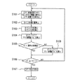
図2に、ECU51で実行されるパティキュレートフィルタ32の再生に関する制御内容を示す。先ずステップS101で、DPF温度、吸入空気量、圧力損失を取り込む。DPF温度は、DPF入口温度とDPF出口温度より演算処理して求める。DPF入口温度は変動が大きいので一次遅れフィルタによる処理を経たものを用いるのがよい。吸入空気量はここでは質量流量である。
【0033】
ステップS102は、ECU51の、補正手段としての処理で、ECU51はエアーフローメータ52とともに流速検出手段を構成する。ステップS102では、先ず、排気ガスの体積流量を算出する。算出は式(1)にしたがって算出する。なお、エアーフローメータ52は、吸気マニホールド21の上流位置に配されている。
体積流量(m3 /sec)
=[吸入空気量(g/sec)/28.8(g/mol)]
×22.4×10⁻³(m3 /mol)
×[DPF温度(K)/273(K)]
×[大気圧(kPa)/(大気圧(kPa)+差圧(kPa))]
+燃料噴射量(cc/sec)/207.3(g/mol)]
×0.84(g/cc)×6.75(mol)
×22.4×10⁻³(m3 /mol)
×[大気圧(kPa)/(大気圧(kPa)+差圧(kPa))]・・・(1)
【0034】
式(1)の第1項は吸入吸気量を質量流量から体積流量に変換したものである。第2項は、噴射燃料の燃焼で、吸入空気量に対して増大する排気ガスの増量分である。第2項中、0.84(g/cc)は軽油の代表的な液密度である。6.75(mol)は燃料噴射量1(mol)に対する増量分のモル数である。
【0035】
増量分(6.75(mol))については以下のように得ている。軽油の組成は代表的には、C15H27.3(分子量207.3)と表され、燃焼時の反応式は次の通りである。
【0036】
C15H27.3+21.75O2 →15CO2 +13.5H2 O
【0037】
したがって、燃料噴射量1molに対し、6.75(=(15+13.5)−21.75)molのモル数の増加がある。
【0038】
また、燃料噴射はECU51で決定される所定の噴射時期にのみ噴射され、間欠的な噴射となる。式(1)中の燃料噴射量は、非噴射期間も合わせた平均的な燃料噴射量である。
【0039】
排気ガスの体積流量は、パティキュレートフィルタ32の有効通路面積で除して、流速に換算される。
【0040】
ステップS103では、排気ガスの粘度μをDPF温度に基づいて算出する。これは、所定の演算式若しくはマップに基づいて行う。図3に排気ガスの粘度と温度の対応関係を示す。
【0041】
ステップS103ではまた、排気ガスの密度ρをDPF温度に基づいて算出する。これは、所定の演算式若しくはマップに基づいて行う。図4に排気ガスの密度と温度の対応関係を示す。
【0042】
ステップS104では、排気微粒子の堆積量(以下、適宜、PM堆積量という)を算出する。PM堆積量の算出式として、次の式(2−1)、式(2−2)をROMに格納している。式中、ML は堆積量、ΔPは圧力損失、vは流速である。式(2−1)のA1 ,B1 ,C1 ,D1 、式(2−2)のA2 ,B2 ,C2 ,D2 は定数である。
【0043】
ML =[ΔP−(A1 μv+C1 ρv2 )]/(B1 μv+D1 ρv2 )
・・・(2−1)
ML =[ΔP−(A2 μv+C2 ρv2 )]/(B2 μv+D2 ρv2 )
・・・(2−2)
【0044】
式(2−1)、式(2−2)について説明する。
【0045】
発明者らは、パティキュレートフィルタについて排気微粒子の堆積と、これが排気ガスの流通におよぼす影響について鋭意実験研究を重ねた結果、次の知見を得た。パティキュレートフィルタ32における圧力損失ΔPと流速vとの間には、モデル式として式(3)の関係があり、係数M,NがPM堆積量が多いほど、大きな値をとることがわかった。
ΔP=Mμv+Nρv2 ・・・・(3)
【0046】
また、圧力損失ΔPはPM堆積量ML に対して一次関数形で変化することが分かった。さらに、この変化は、図5に示すように、PM堆積量ML がある大きさ(以下、適宜、遷移点堆積量という)になる点(以下、適宜、遷移点という)で傾きが不連続に変化する。
【0047】
これは、以下のように、パティキュレートフィルタ32における圧力損失についての理論的なモデルからも導き出される結論であることを発明者らは確認した。図6はパティキュレートフィルタ32内を表したもので、入口32aから流入した排気ガスが出口32bから流出するまでの間に、管摩擦による圧力損失、通路断面積が急拡大したり急縮小することによる圧力損失、フィルタ本体4の隔壁を透過する際の圧力損失がある。以下に各圧力損失ΔPi について説明する。
【0048】
(通路の摩擦による圧力損失)
この圧力損失ΔPi について式(4)と書ける。式中、λは損失の程度を示す係数であり、lは通路の長さであり、dは通路の径である。gは重力定数である。
ΔPi /(ρg)=λ(l/d)(v2 /2g)・・・(4)
【0049】
ここで、Reをレイノルズ数として、層流であればλ=64/Reであり、Re=vd/r、r=μ/ρであるから、式(4)は式(5)と書ける。式中、αは係数である。
ΔPi =αμv・・・(5)
【0050】
(通路断面積の急縮小による圧力損失)
この圧力損失ΔPi について式(6)と書ける。式中、ζは損失の程度を示す係数である。
ΔPi /(ρg)=ζ(v2 /2g)・・・(6)
【0051】
したがって、式(6)は式(7)と書ける。式中、βは係数である。
ΔPi =βρv2 ・・・(7)
【0052】
(通路断面積の急縮小による圧力損失)
この圧力損失ΔPi について式(8)と書ける。式中、ξは損失の程度を示す係数である。
ΔPi /(ρg)=ξ(v2 /2g)・・・(8)
【0053】
したがって、式(8)は式(9)と書ける。式中、γは係数である。
ΔPi =γρv2 ・・・(9)
【0054】
(フィルタ本体4の隔壁を透過する際の圧力損失)
この圧力損失ΔPi について式(10)と書ける。これはエルガンの式として知られている。式中、k1 、k2 は係数、εは気孔率、Sは多孔質体の表面積/体積、L* は透過層の厚さである。
ΔPi g=k1 [(1−ε)2 /ε3 ]S2 L* μv
+k2 [(1−ε)/ε3 ]SL* ρv2 ・・・(10)
【0055】
式(10)は、フィルタ本体4の隔壁について(差圧ΔPiW)と、PM堆積層について(差圧ΔPiS)とのそれぞれについて成立するので、式(11−1)、(11−2)と表せる。式中、LはPM堆積層の厚さである。
ΔPiW=δW μv+ηW ρv2 ・・・(11−1)
ΔPiS=(δS μv+ηS ρv2 )L・・・(11−2)
【0056】
差圧センサ54で検出される圧力損失は、前記各圧力損失ΔPi 、ΔPiW 、ΔPiSを加算したものと考えられ、前記式(3)が成り立つ。PM堆積量が多ければPM堆積層も厚くなるから、PM堆積量が多いほどM,Nは大きくなる。なお、圧力損失ΔPi 、ΔPiW 、ΔPiSの表式において、パティキュレートフィルタ32よりも上流、下流での流速の項を無視しているのは、パティキュレートフィルタ32内部での流速に比してごく小さいからである。
【0057】
また、L=aML とすれば式(12−1)、式(12−2)となる。
M=α+δW +δS L=α+δW +δS aML ・・・・(12−1)
N=β+δS +ηS L=β+δS +ηS aML ・・・・(12−2)
【0058】
式(12−1)、式(12−2)を式(13−1)、式(13−2)と書き換えると、式(3)は式(14)となる。A,B,C,Dは定数である。
M=A+BML ・・・・(13−1)
N=C+DML ・・・・(13−2)
ΔP=(Aμv+Cρv2 )+(Bμv+Dρv2 )ML ・・・・(14)
【0059】
式(14)を変形すると式(15)となる。
ML =[ΔP−(Aμv+Cρv2 )]/(Bμv+Dρv2 )
・・・・(15)
【0060】
ここで、図5の、遷移点堆積量のときを挟んで圧力損失ΔPの変化率が異なることについて説明する。図7(A)、図7(B)、図7(C)は、パティキュレートフィルタ本体4の隔壁で排気微粒子の堆積が進行していく様子を示しており、この順に、PM堆積量が多くなる。
【0061】
図7(A)は排気微粒子が堆積していない新品若しくはパティキュレートフィルタ32を完全に再生した直後の状態であり、パティキュレートフィルタ本体4の隔壁を排気微粒子が透過する際における圧力損失は、パティキュレートフィルタ32の形状諸元で規定される。
【0062】
この状態から図7(B)に示すように、排気微粒子が、隔壁表面に堆積していく他、細孔に詰まっていき、圧力損失が増大するが、図中、矢印で示すように、排気ガスは細孔に向かうように流れていくので、細孔が詰まることが圧力損失の支配要因となる。
【0063】
細孔の多くが詰まり全面にPM堆積層が形成されると、今度は、図7(C)に示すように、PM堆積層の厚さが増大していくことになる。ここでは、隔壁全面を覆うPM堆積層が厚くなることが圧力損失の支配要因となる。
【0064】
このように、細孔の多くが詰まり、全面にPM堆積層が形成される遷移点の前の領域(第1の領域)と後の領域(第2の領域)とで圧力損失の支配要因が異なる。排気微粒子が詰まっていない状態では良好に流通が自在であった細孔が、排気微粒子が細孔で捕集されて細孔に詰まると、急激に圧力損失が増大するので、細孔の多くが詰まるまでは、前記図5に示すように、PM堆積量に対する圧力損失の変化率は比較的、大きい(直線▲1▼)。一方、細孔の多くが詰まってしまった以降では支配要因がPM堆積層の厚さの増大に変わるから、PM堆積量に対する圧力損失の変化率は緩やかなものに変わることになる(直線▲2▼)。
【0065】
式(14)は、PM堆積量に対して圧力損失が直線的に変化していく様子をよく記述するものであるが、遷移点を挟む支配要因の切り換わりを考慮すれば、A,B,C,Dは2種類用意し、これが異なる式を使い分けることで、広い範囲でPM堆積量を高精度に求めることができることになる。これが式(2−1)、式(2−2)である。式(2−1)のA1 ,B1 ,C1 ,D1 は第1の領域でA,B,C,Dを適合したものであり、式(2−2)のA2 ,B2 ,C2 ,D2 は第2の領域でA,B,C,Dを適合したものである。
【0066】
本制御フローでは、この式(2−1)により算出した堆積量が基準値を越えるか否かを判断した後に、越えた場合には次ステップとして式(2−2)を用いて堆積量を算出する。しかし、本制御フローに限定されず、式(2−2)による判断に次いで式(2−1)による算出が行われてもよい。
【0067】
また、基準値である、遷移点となる堆積量のデータは、予め実験的に求められて記憶されている。
【0068】
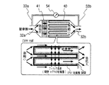
なお、図8のように、酸化触媒が担持されていないフィルタ本体40の上流にフロースルーモノリス担体41が配置された触媒前置き構造のものでも、フロースルーモノリス担体41において管摩擦があり、フロースルーモノリス担体41の入口では急縮小が、出口では急拡大が生じることから、パティキュレートフィルタの構成によらず、圧力損失ΔPは式(2−1)、式(2−2)、式(14)と同様に表される。
【0069】
ステップS104では、第1の領域に適合した式(2−1)によりPM堆積量ML を算出する。
【0070】
ステップS105では、算出されたPM堆積量ML を遷移点のPM堆積量と比較し、PM堆積量ML が遷移点堆積量よりも小さいか否かを判定する。
【0071】
肯定判断されると、ステップS106で、判定式 PM堆積量ML ≧基準堆積量MLth が成り立つか否かを判定する。基準堆積量MLth は、機関背圧や出力の低下がさほどでなくパティキュレートフィルタ32の再生をしないことが許容される堆積量の上限値を考慮して設定する。
【0072】
ステップS106が否定判断されると、ステップS101に戻り、ステップS101以降の手順が実行される。
【0073】
そして、パティキュレートフィルタ32において排気微粒子の堆積が進むと、ステップS105が否定判断されることになる。否定判断されるとステップS108に進み、遷移点以後の第2領域に適合した式(2−2)によりPM堆積量ML を算出する。これにより、より正確なPM堆積量が知られる。
【0074】
そして、ステップS106が肯定判断されるとステップS107に進み、パティキュレートフィルタ32の再生を実施する。これは例えばポスト噴射等が用いられる。
【0075】
このように、本排気ガス浄化装置では、PM堆積量を正確に知ることで適正な時期にパティキュレートフィルタ32の再生を実施することができるので、再生時期が早すぎて燃費が悪化したり、再生時期が遅すぎて内燃機関の出力の低下やパティキュレートフィルタ32での異常な昇温を招いたりすることを防止することができる。
【0076】
しかも、式(2−1)、式(2−2)を記憶していればよいから、マップのようにデータが大規模化しない。
【0077】
次に、ECU51で実行される別の制御フローを図9に示す。これは、パティキュレートフィルタ32の再生の実施中に実行される制御フローであり、再生の開始とともに実行される。ステップS201〜S205は、堆積量低下状態検出手段としての処理である。
【0078】
先ず、ステップS201でタイマのカウントをスタートさせるとともに、ステップS202で式(2−2)によりPM堆積量を算出し、これを変化前値MLiとする。
【0079】
ステップS203ではタイマのカウント値tを予め設定した基準時間t0 と比較し、カウント値tが基準時間t0 に達したか否かを判定し、肯定判断、すなわち基準時間が経過すると、ステップS204に進む。
【0080】
ステップS204では、式(2−2)によりPM堆積量を算出し、これを変化後値MLfとする。
【0081】
ステップS205では、PM堆積量の差分ΔML を式(16)により算出する。
ΔML =MLi−MLf・・・(16)
【0082】
ステップS206は触媒劣化判定手段としての処理であり、差分ΔML をしきい値ΔML0と比較し、差分ΔML がしきい値ΔML0よりも小さいか否かを判定し、肯定判断されると、ステップS207で警告灯55を点灯せしめ、本フローを終了する。ステップS206が否定判断されると、ステップS207をスキップして、本フローを終了する。
【0083】
PM堆積量の差分ΔML は、一定時間t0 内のPM堆積量の低減量であり、再生の進行速度を示している。これはパティキュレートフィルタ本体4に担持した触媒が劣化していると遅くなる。例えば経時劣化により、図10のように走行距離が進むと漸次、遅くなる。
【0084】
しきい値ΔML0を、触媒が正常とみなせる差分ΔML の下限値(図中の触媒性能規定値に対応する)に設定することで、触媒の異常の発生や、交換すべき時期を適正に運転者に報知することができる。
【0085】
なお、本制御フローはパティキュレートフィルタ32の再生開始とともに実行しており、また、再生はPM堆積量が上限堆積量MLth に達すると開始されるから、変化前値MLiは略上限堆積量MLth である。したがって、常に略同じ条件でPM堆積量の低下状態を検出することができるが、PM堆積量が予め設定した所定値になった時点でカウンタをスタートするようにしてもよい。この場合、カウンタをスタートさせる時のPM堆積量を、上限堆積量MLth よりもある程度小さな値に設定し、PM堆積量の燃焼が十分に進行している状態で計測するようにしてもよい。この場合、カウンタをスタートさせる時のPM堆積量が第1領域であってもよい。遷移点よりも前か後かでPM堆積量の算出に用いる式を式(2−1)と式(2−2)とで切り換えるのは勿論である。
【0086】
また、基準時間t0 後のPM堆積量の変化をみるのではなく、再生中に、予め設定したPM堆積量になった時点から、別の予め設定したPM堆積量になる時点までの経過時間をカウントし、この経過時間が基準の時間よりも長くなったら酸化触媒の劣化と判断するのもよい。
【0087】
なお、本実施形態では、PM堆積量を、圧力損失ΔP、体積流量V、DPF入口温度およびDPF出口温度から算出した粘度μおよび密度ρに基づいて算出し、PM堆積量の大きさで再生が必要か否かを判定しているが、式(3)を利用するものであればよい。例えば、M,Nを再生が必要な基準のPM堆積量に対応する値として、ΔP(v,μ,ρ)=Mμv+Nρv2 を算出するようにし、判定式 ΔP≧ΔP(v,μ,ρ)が成り立つか否かを判定する。再生が必要でなければ、ΔP<ΔP(v,μ,ρ)で判定式は不成立であり、再生が必要であればΔP≧ΔP(v,μ,ρ)で判定式は成立となる。
【0088】
本実施形態ではμ,ρを2つの温度センサにより検出したDPF入口温度およびDPF出口温度に基づいて算出しているが、いずれか一つの温度センサのみの温度に基づいて算出してもよい。この場合、検出温度に所定のオフセット温度を加減したものを、DPF温度としてもよい。あるいは、要求される仕様によっては、粘度μおよび密度ρのいずれかひとつまたは両方を固定値とするのもよい。いずれか一つを固定値とする場合には、PM堆積量への依存性の小さいものの方を固定値とするのは勿論である。
【0089】
また、式(1)では燃料噴射による体積流量の増分を考慮しているが、要求される仕様によっては式(1)の第1項を排気ガスの体積流量としてもよい。また、排気ガスの体積流量を、エアフローメータ52により検出された吸入空気量を用いて算出するのではなく、排気通路3に流速を検出するセンサを設けて、直接に流速を検出するのもよい。
【図面の簡単な説明】
【図1】本発明の排気ガス浄化装置を適用した内燃機関の構成図である。
【図2】前記内燃機関の各部を制御するECUで実行される制御内容を示す第1のフローチャートである。
【図3】内燃機関が排出する排気ガスの粘度と温度との関係の一例を示すグラフである。
【図4】内燃機関が排出する排気ガスの密度と温度との関係の一例を示すグラフである。
【図5】前記パティキュレートフィルタにおける排気微粒子の堆積量と圧力損失との関係を示すグラフである。
【図6】前記排気ガス浄化装置のパティキュレートフィルタ内部における排気ガスの流通を示す図である。
【図7】(A)、(B)、(C)は、それぞれ前記排気ガス浄化装置のパティキュレートフィルタに排気微粒子が堆積していく状態を示す堆積量の異なる図である。
【図8】別の構造を有するパティキュレートフィルタ内部における排気ガスの流通を示す図である。
【図9】前記内燃機関の各部を制御するECUで実行される制御内容を示す第2のフローチャートである。
【図10】走行距離と、パティキュレートフィルタの再生時の排気微粒子浄化速度との関係を示すグラフである。
【符号の説明】
1 エンジン本体
2 吸気通路
21 吸気マニホールド
3 排気通路
31 排気マニホールド
32 パティキュレートフィルタ
32a 入口
32b 出口
4 本体
51 ECU(再生決定手段、補正手段、堆積量低下状態検出手段、触媒劣化判定手段)
52 エアフローメータ(吸入空気量検出手段)
53 温度センサ(温度検出手段)
54 差圧センサ(差圧検出手段)
55 警告灯[0001]
BACKGROUND OF THE INVENTION
The present invention relates to an exhaust gas purification device for an internal combustion engine, and more particularly to a technique for regenerating a particulate filter.
[0002]
[Prior art]
In recent years, internal combustion engines mounted on automobiles and the like have been required to improve exhaust emissions. In particular, compression ignition type diesel engines using light oil as a fuel are included in exhaust gas in addition to CO, HC and NOx. It is necessary to remove exhaust particulates such as soot and SOF. For this reason, a particulate filter is disposed in the exhaust passage, where exhaust particulates in the exhaust gas are collected.
[0003]
The particulate filter allows the inflowing exhaust gas to permeate through the porous partition walls, and at that time, collects exhaust particulates in the exhaust gas through the surfaces and pores of the partition walls. If the amount collected and accumulated excessively increases, the back pressure of the internal combustion engine increases due to an increase in flow resistance in the particulate filter, resulting in a decrease in output. For this reason, it is necessary to appropriately remove the exhaust particulates collected by the particulate filter from the particulate filter, regenerate the particulate filter, and restore the exhaust particulate collection ability of the particulate filter.
[0004]
A particulate filter that can be regenerated during operation of the internal combustion engine is one in which an oxidation catalyst such as platinum is provided on the particulate filter and the oxidation action of the oxidation catalyst is utilized. In this apparatus, for example, fuel is supplied to the particulate filter by post-injection in which fuel is injected in the exhaust stroke, and the accumulated exhaust particulates that are difficult to oxidize compared to the injected fuel are oxidized and removed using the combustion heat.
[0005]
If the particulate filter is regenerated frequently, the fuel efficiency will deteriorate. On the other hand, if there is too much space until the next regeneration, the accumulated amount of exhaust particulates will be excessive, and the exhaust particulates will burn rapidly in the regeneration process, causing the particulates to regenerate. The curate filter becomes extremely hot and may be damaged. For this reason, it is desirable to determine the regeneration time by judging the amount of exhaust particulates deposited. Japanese Patent Application Laid-Open No. 7-332065 utilizes the fact that the difference in pressure between the inlet and outlet of the particulate filter increases due to the increase in the ventilation resistance due to the increase in the amount of exhaust particulates deposited on the particulate filter. The pressure difference is detected, and when the detected pressure difference exceeds a predetermined value, it is determined that it is time to regenerate.
[0006]
[Problems to be solved by the invention]
However, according to the technique disclosed in Japanese Patent Laid-Open No. 7-332065, the accumulated amount of exhaust particulates varies depending on the operating state of the internal combustion engine even if a differential pressure of the same magnitude is detected. Some cannot be judged. Although it is conceivable to store a detailed map for each operation state, a large storage capacity is required, which is not easy.
[0007]
The present invention has been made in view of the above circumstances, and an object of the present invention is to provide an exhaust gas purifying device for an internal combustion engine that can appropriately determine the regeneration timing with a simple configuration.
[0008]
[Means for Solving the Problems]
The inventors have conducted extensive experimental research on the accumulation of exhaust particulates and the effect of this on the exhaust gas flow, and as a result, the differential pressure between the inlet side and the outlet side of the particulate filter, that is, If the pressure loss in the particulate filter is ΔP, the flow velocity of the exhaust gas flowing through the particulate filter is v, the viscosity of the exhaust gas is μ, and the density of the exhaust gas is ρ, the model equation ΔP = Mμv + Nρv 2 It was found that the coefficients M and N take larger values as the amount of exhaust particulates increases. Specifically, M and N substantially take a linear function form of the deposition amount ML, and when the deposition amount exceeds a certain value, the rate of change of M and N with respect to the deposition amount ML decreases. The difference in the pressure before and after sandwiching a certain value is that the pressure loss in the particulate filter initially increases with the proportion of the pores of the particulate filter that are clogged with exhaust particulates. On the other hand, when the pores are substantially clogged with exhaust particulates, it is recognized that the pores increase in accordance with the thickness of the exhaust particulate deposition layer. The present invention has been made based on such findings.
[0009]
In the invention according to
Differential pressure detecting means for detecting a differential pressure between the inlet side and the outlet side of the particulate filter;
A flow rate detecting means for detecting a flow rate of exhaust gas flowing through the particulate filter;
Regeneration determining means for determining whether or not to regenerate the particulate filter according to a determination formula for determining the amount of exhaust particulate accumulated on the particulate filter based on a detected differential pressure and a detected flow velocity; It is set as the structure to comprise.
In addition, the determination formula is as follows: ΔP ≧ ΔP, flow velocity v, viscosity of exhaust gas flowing through the particulate filter μ, density of the exhaust gas ρ, and constants M and N, Mμv + Nρv 2 The particulate filter is allowed to be regenerated when this condition is satisfied.
[0010]
As described above, ΔP = Mμv + Nρv regarding the flow of exhaust gas in the particulate filter. 2 Therefore, if M and N are obtained with respect to the reference accumulation amount, it is possible to accurately determine the amount of exhaust particulate accumulation from the determination formula. In addition, since the formulas need only be stored, the size of the stored data does not increase as in the case of a map.
[0011]
According to a second aspect of the present invention, in the configuration of the first aspect of the invention, the regeneration determining means uses the constants A, B, C, and D as the deposition amount ML.
ML = [ΔP− (Aμv + Cρv 2 )] / (Bμv + Dρv 2 ) And the determination formula is a determination formula for comparing the calculated deposition amount with a predetermined deposition amount.
[0012]
Since M and N take a linear function form of the deposition amount ML as described above, the model equation ΔP = Mμv + Nρv 2 The formula for calculating ML is established. The amount of exhaust particulate accumulation is known objectively.
[0013]
According to a third aspect of the present invention, in the configuration of the second aspect of the invention, the regeneration determining means has two types of calculation formulas in which the constants A, B, C, and D have different values as the calculation formulas for the accumulation amount. A calculation formula is stored in which one calculation formula is suitable for a deposition amount in a range not more than a preset reference value, and the other calculation formula is suitable for a deposition amount in a range not less than the reference value. And
When the deposition amount calculated by the calculation formula is out of the range of the deposition amount to which the calculation formula fits, the deposition amount is set to be recalculated by the remaining calculation formulas.
[0014]
Even if the governing factor for the pressure loss in the particulate filter changes, a more appropriate determination formula is selected, so that the amount of exhaust particulates accumulated can be known more accurately.
[0015]
According to a fourth aspect of the present invention, in the configuration of the second or third aspect of the invention, the particulate filter is a particulate filter having an oxidation catalyst that oxidizes and burns exhaust particulates deposited on the particulate filter,
During the regeneration of the particulate filter, a deposition amount lowering state detecting means for detecting a lowering state of the calculated deposition amount;
The catalyst deterioration determining means for determining that the oxidation catalyst has deteriorated as the calculated accumulation amount decreases more slowly is provided.
[0016]
When the oxidation catalyst is deteriorated and its oxidation ability is reduced, the combustion rate of the accumulated exhaust particulates becomes dull during regeneration of the particulate filter, so that the rate of decrease in the accumulation amount becomes dull. Therefore, it is possible to determine the presence / absence or deterioration of the particulate filter based on the reduced state of the calculated accumulation amount.
[0017]
According to the invention of claim 5, in the configuration of the invention of
The regeneration determining means is set so as to obtain the viscosity μ from the detected temperature based on the correspondence relationship between the viscosity and temperature of the exhaust gas stored in advance.
[0018]
Since the viscosity μ of the exhaust gas is more accurately known, a more appropriate determination formula can be given.
[0019]
According to a sixth aspect of the present invention, in the configuration of the first to fifth aspects of the present invention, temperature detection means for detecting the temperature of the exhaust gas flowing through the particulate filter is provided,
The regeneration determining means is set so as to obtain the density ρ from the detected temperature based on the correspondence relationship between the density and temperature of the exhaust gas stored in advance.
[0020]
Since the density ρ of the exhaust gas is more accurately known, a more appropriate determination formula can be given.
[0021]
According to a seventh aspect of the present invention, in the configuration of the first to sixth aspects of the invention, the flow velocity detecting means includes:
An intake air amount detecting means for detecting the intake air amount of the internal combustion engine, and adding a volume which is increased by combustion of the injected fuel to the intake air amount, and this is added to the volume flow rate of the exhaust gas flowing through the particulate filter. And correcting means for converting the volume flow rate into the flow velocity.
[0022]
When the injected fuel burns in the cylinder, the volume flow rate of the exhaust gas increases from the intake air amount in accordance with the amount of fuel provided for combustion. Therefore, the exhaust gas volume flow rate can be accurately obtained without directly measuring the exhaust gas containing the exhaust particulates. Since the flow rate of the exhaust gas flowing through the particulate filter is proportional to the coefficient defined by the shape of the particulate filter and the like, it can be converted from the volume flow rate.
[0023]
If the flow rate of exhaust gas containing exhaust particulates from the cylinder is detected directly, the detection sensor may be contaminated by exhaust particulates and affect the detection characteristics, but it can detect the flow rate of relatively clean intake air. Therefore, the detection characteristics are not affected, and the flow rate of the exhaust gas can be detected with high reliability.
[0024]
An ordinary internal combustion engine is provided with an air flow meter as intake air amount detection means, and the intake air amount detected here can be used as it is, so that the configuration is simple.
[0025]
DETAILED DESCRIPTION OF THE INVENTION
FIG. 1 shows the configuration of a diesel engine according to a first embodiment to which the present invention is applied. In a diesel engine, an
[0026]
An
[0027]
Various signals indicating the operating state are input to the
[0028]
Further, the
[0029]
The
[0030]
In addition, it is a matter of course that parameters indicating the operation state such as the accelerator opening and the coolant temperature are input to the
[0031]
The
[0032]
FIG. 2 shows the control contents relating to the regeneration of the
[0033]
Step S102 is a process performed by the
Volume flow (m 3 / Sec)
= [Intake air amount (g / sec) /28.8 (g / mol)]
× 22.4 × 10 -3 (M 3 / Mol)
× [DPF temperature (K) / 273 (K)]
× [Atmospheric pressure (kPa) / (Atmospheric pressure (kPa) + Differential pressure (kPa))]
+ Fuel injection amount (cc / sec) / 207.3 (g / mol)]
× 0.84 (g / cc) × 6.75 (mol)
× 22.4 × 10 -3 (M 3 / Mol)
× [Atmospheric pressure (kPa) / (Atmospheric pressure (kPa) + Differential pressure (kPa))] (1)
[0034]
The first term of the equation (1) is obtained by converting the intake air intake amount from the mass flow rate to the volume flow rate. The second term is an increase in the amount of exhaust gas that increases with respect to the intake air amount due to combustion of the injected fuel. In the second term, 0.84 (g / cc) is a typical liquid density of light oil. 6.75 (mol) is the number of moles corresponding to an increase with respect to the fuel injection amount 1 (mol).
[0035]
The increased amount (6.75 (mol)) is obtained as follows. The composition of light oil is typically C 15 H 27.3 It is expressed as (molecular weight 207.3), and the reaction formula at the time of combustion is as follows.
[0036]
C 15 H 27.3 + 21.75O 2 → 15CO 2 + 13.5H 2 O
[0037]
Therefore, there is an increase in the number of moles of 6.75 (= (15 + 13.5) -21.75) mol with respect to 1 mol of the fuel injection amount.
[0038]
Further, the fuel is injected only at a predetermined injection timing determined by the
[0039]
The volume flow rate of the exhaust gas is divided by the effective passage area of the
[0040]
In step S103, the viscosity μ of the exhaust gas is calculated based on the DPF temperature. This is performed based on a predetermined arithmetic expression or a map. FIG. 3 shows the correspondence between the exhaust gas viscosity and temperature.
[0041]
In step S103, the exhaust gas density ρ is calculated based on the DPF temperature. This is performed based on a predetermined arithmetic expression or a map. FIG. 4 shows the correspondence between exhaust gas density and temperature.
[0042]
In step S104, an accumulation amount of exhaust particulates (hereinafter referred to as PM accumulation amount as appropriate) is calculated. The following formulas (2-1) and (2-2) are stored in the ROM as formulas for calculating the PM deposition amount. In the formula, ML is the deposition amount, ΔP is the pressure loss, and v is the flow velocity. A1, B1, C1, and D1 in Formula (2-1) and A2, B2, C2, and D2 in Formula (2-2) are constants.
[0043]
ML = [ΔP− (A1 μv + C1 ρv 2 )] / (B1 μv + D1 ρv 2 )
... (2-1)
ML = [ΔP− (A2 μv + C2 ρv 2 )] / (B2 μv + D2 ρv 2 )
... (2-2)
[0044]
The expressions (2-1) and (2-2) will be described.
[0045]
The inventors of the present invention have obtained the following knowledge as a result of intensive experimental research on the accumulation of exhaust particulates and the effect of this on the exhaust gas flow in the particulate filter. Between the pressure loss ΔP and the flow velocity v in the
ΔP = Mμv + Nρv 2 .... (3)
[0046]
Further, it was found that the pressure loss ΔP changes in a linear function form with respect to the PM deposition amount ML. Further, as shown in FIG. 5, this change is discontinuous in slope at a point (hereinafter referred to as a transition point deposition amount) where the PM deposition amount ML becomes a certain size (hereinafter referred to as a transition point deposition amount as appropriate). Change.
[0047]
The inventors have confirmed that this is a conclusion derived from a theoretical model of pressure loss in the
[0048]
(Pressure loss due to passage friction)
This pressure loss ΔPi can be written as equation (4). In the equation, λ is a coefficient indicating the degree of loss, l is the length of the passage, and d is the diameter of the passage. g is a gravitational constant.
ΔPi / (ρg) = λ (l / d) (v 2 / 2g) (4)
[0049]
Here, if Re is the Reynolds number and λ = 64 / Re for a laminar flow, Re = vd / r, and r = μ / ρ, Equation (4) can be written as Equation (5). In the formula, α is a coefficient.
ΔPi = αμv (5)
[0050]
(Pressure loss due to rapid reduction of passage cross-sectional area)
This pressure loss ΔPi can be written as equation (6). In the equation, ζ is a coefficient indicating the degree of loss.
ΔPi / (ρg) = ζ (v 2 / 2g) (6)
[0051]
Therefore, Equation (6) can be written as Equation (7). In the formula, β is a coefficient.
ΔPi = βρv 2 ... (7)
[0052]
(Pressure loss due to rapid reduction of passage cross-sectional area)
This pressure loss ΔPi can be written as equation (8). In the equation, ξ is a coefficient indicating the degree of loss.
ΔPi / (ρg) = ξ (v 2 / 2g) (8)
[0053]
Therefore, equation (8) can be written as equation (9). In the formula, γ is a coefficient.
ΔPi = γρv 2 ... (9)
[0054]
(Pressure loss when passing through the partition wall of the filter body 4)
This pressure loss ΔPi can be written as equation (10). This is known as the Ergan formula. In the formula, k1 and k2 are coefficients, ε is the porosity, S is the surface area / volume of the porous body, L * Is the thickness of the transmission layer.
ΔPig = k1 [(1-ε) 2 / Ε 3 ] S 2 L * μv
+ K2 [(1-ε) / ε 3 ] SL * ρv 2 ... (10)
[0055]
Since Expression (10) holds for each of the partition wall of the filter body 4 (differential pressure ΔPiW) and the PM deposition layer (differential pressure ΔPiS), it can be expressed as Expressions (11-1) and (11-2). . Where L is the thickness of the PM deposit layer.
ΔPiW = δW μv + ηW ρv 2 ... (11-1)
ΔPiS = (δS μv + ηS ρv 2 ) L ... (11-2)
[0056]
The pressure loss detected by the
[0057]
Moreover, if L = aML, it will become Formula (12-1) and Formula (12-2).
M = α + δW + δS L = α + δW + δS aML (12-1)
N = β + δS + ηS L = β + δS + ηS aML (12-2)
[0058]
When Expression (12-1) and Expression (12-2) are rewritten as Expression (13-1) and Expression (13-2), Expression (3) becomes Expression (14). A, B, C, and D are constants.
M = A + BML (13-1)
N = C + DML (13-2)
ΔP = (Aμv + Cρv 2 ) + (Bμv + Dρv 2 ) ML (14)
[0059]
When Expression (14) is transformed, Expression (15) is obtained.
ML = [ΔP− (Aμv + Cρv 2 )] / (Bμv + Dρv 2 )
.... (15)
[0060]
Here, the fact that the rate of change of the pressure loss ΔP is different across the transition point accumulation amount in FIG. 5 will be described. FIGS. 7A, 7B, and 7C show a state in which the accumulation of exhaust particulates proceeds in the partition wall of the
[0061]
FIG. 7A shows a new product in which exhaust particulates are not deposited or a state immediately after the
[0062]
From this state, as shown in FIG. 7 (B), exhaust particulates accumulate on the partition wall surface and clog the pores, increasing the pressure loss. However, as shown by the arrows in FIG. Since the gas flows toward the pores, the clogging of the pores becomes the dominant factor of the pressure loss.
[0063]
When many of the pores are clogged and a PM deposition layer is formed on the entire surface, the thickness of the PM deposition layer will increase as shown in FIG. 7C. Here, the thickening of the PM deposition layer covering the entire partition wall is the dominant factor of the pressure loss.
[0064]
Thus, many of the pores are clogged, and the dominant factor of pressure loss is the region before the transition point (first region) and the region after the second region (second region) where the PM deposit layer is formed on the entire surface. Different. Since the fine pores that could be freely distributed in a state where the exhaust particulates are not clogged, but the exhaust particulates are collected in the pores and clogged, the pressure loss increases rapidly, so many of the pores Until clogging, as shown in FIG. 5, the rate of change of pressure loss relative to the amount of PM deposition is relatively large (straight line (1)). On the other hand, after many of the pores are clogged, the controlling factor changes to an increase in the thickness of the PM deposition layer, so the rate of change in pressure loss with respect to the amount of PM deposition changes to a gradual one (
[0065]
Equation (14) is a good description of how the pressure loss changes linearly with respect to the amount of accumulated PM, but considering the change of the dominant factors across the transition point, A, B, By preparing two types of C and D and using different formulas for them, the PM deposition amount can be obtained with high accuracy in a wide range. This is Equation (2-1) and Equation (2-2). A1, B1, C1, and D1 in the formula (2-1) are obtained by adapting A, B, C, and D in the first region, and A2, B2, C2, and D2 in the formula (2-2) are In the area of 2, A, B, C, and D are adapted.
[0066]
In this control flow, after determining whether or not the deposition amount calculated by the equation (2-1) exceeds the reference value, if it exceeds, the deposition amount is calculated using the equation (2-2) as the next step. calculate. However, it is not limited to this control flow, and the calculation according to equation (2-1) may be performed following the determination according to equation (2-2).
[0067]
Further, the data of the deposition amount serving as the transition point, which is the reference value, is obtained experimentally and stored in advance.
[0068]
As shown in FIG. 8, even in the structure of the catalyst front structure in which the flow-through
[0069]
In step S104, the PM deposition amount ML is calculated by the equation (2-1) adapted to the first region.
[0070]
In step S105, the calculated PM deposition amount ML is compared with the PM deposition amount at the transition point, and it is determined whether the PM deposition amount ML is smaller than the transition point deposition amount.
[0071]
If an affirmative determination is made, it is determined in step S106 whether or not the determination formula PM accumulation amount ML ≧ reference accumulation amount MLth is satisfied. The reference accumulation amount MLth is set in consideration of the upper limit value of the accumulation amount in which the reduction of the engine back pressure and the output is not so much that the
[0072]
If a negative determination is made in step S106, the process returns to step S101, and the procedure after step S101 is executed.
[0073]
Then, when the accumulation of exhaust particulates proceeds in the
[0074]
If an affirmative determination is made in step S106, the process proceeds to step S107, where the
[0075]
In this way, in the present exhaust gas purification device, the
[0076]
In addition, since the equations (2-1) and (2-2) need only be stored, the data does not become large like a map.
[0077]
Next, another control flow executed by the
[0078]
First, in step S201, the timer starts counting, and in step S202, the PM deposition amount is calculated by the equation (2-2), and this is set as a pre-change value MLi.
[0079]
In step S203, the timer count value t is compared with a preset reference time t0 to determine whether or not the count value t has reached the reference time t0. .
[0080]
In step S204, the PM accumulation amount is calculated by the equation (2-2), and this is set as a post-change value MLf.
[0081]
In step S205, the PM accumulation amount difference ΔML is calculated by the equation (16).
ΔML = MLi−MLf (16)
[0082]
Step S206 is a process as a catalyst deterioration determination means. The difference ΔML is compared with a threshold value ΔML0 to determine whether or not the difference ΔML is smaller than the threshold value ΔML0. The warning
[0083]
The difference ΔML in the PM deposition amount is a reduction amount of the PM deposition amount within a predetermined time t0 and indicates the progress speed of regeneration. This is delayed when the catalyst carried on the
[0084]
By setting the threshold value ΔML0 to the lower limit value of the difference ΔML that can be regarded as normal for the catalyst (corresponding to the specified catalyst performance value in the figure), the driver can properly detect the occurrence of catalyst abnormality and the time to replace it. Can be notified.
[0085]
This control flow is executed with the start of regeneration of the
[0086]
In addition, instead of looking at the change in the PM deposition amount after the reference time t0, the elapsed time from the time when the PM deposition amount is preset during the regeneration to the time when the PM deposition amount becomes another preset is obtained. Counting may be performed and it may be determined that the oxidation catalyst has deteriorated when the elapsed time becomes longer than the reference time.
[0087]
In this embodiment, the PM deposition amount is calculated based on the pressure loss ΔP, the volume flow rate V, the viscosity μ and the density ρ calculated from the DPF inlet temperature and the DPF outlet temperature, and the regeneration is performed with the magnitude of the PM deposition amount. Although it is determined whether or not it is necessary, it may be anything that uses Equation (3). For example, ΔP (v, μ, ρ) = Mμv + Nρv, where M and N are values corresponding to the reference PM deposition amount that needs to be regenerated. 2 Is calculated, and it is determined whether or not the determination formula ΔP ≧ ΔP (v, μ, ρ) is satisfied. If reproduction is not necessary, the determination formula is not established because ΔP <ΔP (v, μ, ρ), and if reproduction is necessary, the determination formula is established if ΔP ≧ ΔP (v, μ, ρ).
[0088]
In the present embodiment, μ and ρ are calculated based on the DPF inlet temperature and the DPF outlet temperature detected by the two temperature sensors, but may be calculated based on the temperature of only one of the temperature sensors. In this case, a value obtained by adding or subtracting a predetermined offset temperature to the detected temperature may be used as the DPF temperature. Alternatively, depending on the required specifications, one or both of the viscosity μ and the density ρ may be fixed. When any one of them is a fixed value, it is a matter of course that the one having a smaller dependence on the PM deposition amount is set as a fixed value.
[0089]
In addition, although the increase in volume flow rate due to fuel injection is taken into account in equation (1), the first term in equation (1) may be used as the volume flow rate of exhaust gas depending on the required specifications. Further, instead of calculating the volume flow rate of the exhaust gas using the intake air amount detected by the
[Brief description of the drawings]
FIG. 1 is a configuration diagram of an internal combustion engine to which an exhaust gas purification apparatus of the present invention is applied.
FIG. 2 is a first flowchart showing details of control executed by an ECU that controls each part of the internal combustion engine.
FIG. 3 is a graph showing an example of the relationship between the viscosity and temperature of exhaust gas discharged from an internal combustion engine.
FIG. 4 is a graph showing an example of the relationship between the density and temperature of exhaust gas discharged from an internal combustion engine.
FIG. 5 is a graph showing the relationship between the amount of exhaust particulates deposited in the particulate filter and the pressure loss.
FIG. 6 is a diagram showing the flow of exhaust gas inside the particulate filter of the exhaust gas purification device.
FIGS. 7A, 7B, and 7C are diagrams showing different accumulation amounts, each showing a state in which exhaust particulates are deposited on the particulate filter of the exhaust gas purification device.
FIG. 8 is a diagram showing the flow of exhaust gas inside a particulate filter having another structure.
FIG. 9 is a second flowchart showing the contents of control executed by an ECU that controls each part of the internal combustion engine.
FIG. 10 is a graph showing the relationship between the travel distance and the exhaust particulate purification speed during regeneration of the particulate filter.
[Explanation of symbols]
1 Engine body
2 Air intake passage
21 Intake manifold
3 Exhaust passage
31 Exhaust manifold
32 Particulate filter
32a entrance
32b exit
4 Body
51 ECU (regeneration determination means, correction means, accumulation amount decrease state detection means, catalyst deterioration determination means)
52 Air flow meter (intake air volume detection means)
53 Temperature sensor (temperature detection means)
54 Differential pressure sensor (Differential pressure detection means)
55 Warning light
Claims (7)
前記パティキュレートフィルタの入口側と出口側との間の差圧を検出する差圧検出手段と、
前記パティキュレートフィルタを流通する排気ガスの流速を検出する流速検出手段と、
前記パティキュレートフィルタに堆積した排気微粒子の堆積量の多少を検出差圧と検出流速とに基づいて判定する判定式にしたがって、前記パティキュレートフィルタを再生するか否かを決定する再生決定手段とを具備し、
前記判定式は、前記差圧をΔP、前記流速をv、前記パティキュレートフィルタを流通する排気ガスの粘度をμ、前記排気ガスの密度をρとし、定数M,Nを用いて、ΔP≧Mμv+Nρv2 と等価であり、これを満たしたときに前記パティキュレートフィルタの再生が許容されることを特徴とする内燃機関の排気ガス浄化装置。In the exhaust gas purification apparatus for an internal combustion engine having a particulate filter that collects exhaust particulates in the middle of the exhaust passage,
Differential pressure detecting means for detecting a differential pressure between the inlet side and the outlet side of the particulate filter;
A flow rate detecting means for detecting a flow rate of exhaust gas flowing through the particulate filter;
Regeneration determining means for determining whether or not to regenerate the particulate filter according to a determination formula for determining the amount of exhaust particulate accumulated on the particulate filter based on a detected differential pressure and a detected flow velocity; Equipped,
The determination formula is as follows: ΔP ≧ Mμv + Nρv, where ΔP is the differential pressure, v is the flow velocity, μ is the viscosity of the exhaust gas flowing through the particulate filter, μ is the density of the exhaust gas, and constants M and N are used. 2. An exhaust gas purifying apparatus for an internal combustion engine, which is equivalent to 2 and permits regeneration of the particulate filter when the condition is satisfied.
ML =[ΔP−(Aμv+Cρv2 )]/(Bμv+Dρv2 )により算出するように設定し、かつ、前記判定式を、算出された堆積量を予め設定した堆積量と大小を比較する判定式とした内燃機関の排気ガス浄化装置。The exhaust gas purifying device for an internal combustion engine according to claim 1, wherein the regeneration determining means uses the constants A, B, C, and D as the accumulation amount ML.
ML = [ΔP− (Aμv + Cρv 2 )] / (Bμv + Dρv 2 ) is set to be calculated, and the determination formula is a determination formula for comparing the calculated deposition amount with a preset deposition amount. An exhaust gas purification device for an internal combustion engine.
算出式により算出された堆積量がその算出式が適合する堆積量の範囲を外れると、堆積量を残りの算出式により算出し直すように設定した内燃機関の排気ガス浄化装置。3. The exhaust gas purifying apparatus for an internal combustion engine according to claim 2, wherein the regeneration determining means includes two types of calculation formulas for calculating the accumulation amount, wherein constants A, B, C, and D have different values. , One calculation formula is adapted for a deposition amount in a range equal to or less than a preset reference value, and the other calculation formula is adapted for a deposition amount in a range equal to or greater than the reference value.
An exhaust gas purifying apparatus for an internal combustion engine, which is set so that when the accumulation amount calculated by the calculation formula is out of the range of the accumulation amount to which the calculation formula is suitable, the accumulation amount is recalculated by the remaining calculation formula.
前記パティキュレートフィルタの再生中に、算出堆積量の低下状態を検出する堆積量低下状態検出手段と、
算出堆積量の低下が遅いほど、前記酸化触媒が劣化しているものと判定する触媒劣化判定手段とを具備せしめた内燃機関の排気ガス浄化装置。The exhaust gas purification apparatus for an internal combustion engine according to claim 2 or 3, wherein the particulate filter is a particulate filter having an oxidation catalyst that oxidizes and burns exhaust particulates deposited on the particulate filter,
During the regeneration of the particulate filter, a deposition amount lowering state detecting means for detecting a lowering state of the calculated deposition amount;
An exhaust gas purifying apparatus for an internal combustion engine, comprising catalyst deterioration determination means for determining that the oxidation catalyst is deteriorated as the calculated accumulation amount decreases more slowly.
前記再生決定手段を、予め記憶した排気ガスの粘度と温度との対応関係に基づいて、検出温度から前記粘度μを求めるように設定した内燃機関の排気ガス浄化装置。The exhaust gas purifying device for an internal combustion engine according to any one of claims 1 to 4, further comprising temperature detecting means for detecting the temperature of the exhaust gas flowing through the particulate filter,
An exhaust gas purifying apparatus for an internal combustion engine, wherein the regeneration determining means is set to obtain the viscosity μ from a detected temperature based on a correspondence relationship between the viscosity and temperature of the exhaust gas stored in advance.
前記再生決定手段を、予め記憶した排気ガスの密度と温度との対応関係に基づいて、検出温度から前記密度ρを求めるように設定した内燃機関の排気ガス浄化装置。The exhaust gas purifying device for an internal combustion engine according to any one of claims 1 to 5, further comprising temperature detecting means for detecting the temperature of the exhaust gas flowing through the particulate filter,
An exhaust gas purifying apparatus for an internal combustion engine, wherein the regeneration determining means is set so as to obtain the density ρ from a detected temperature based on a correspondence relationship between exhaust gas density and temperature stored in advance.
内燃機関の吸入空気量を検出する吸入空気量検出手段と、吸入空気量に、噴射燃料の燃焼で増大する体積分を加算して、これを、前記パティキュレートフィルタを流通する排気ガスの体積流量とする補正手段とを具備せしめ、体積流量から流速に換算するようにした内燃機関の排気ガス浄化装置。The exhaust gas purification apparatus for an internal combustion engine according to any one of claims 1 to 6, wherein the flow velocity detection means includes
An intake air amount detecting means for detecting the intake air amount of the internal combustion engine, and adding a volume which is increased by combustion of the injected fuel to the intake air amount, and this is added to the volume flow rate of the exhaust gas flowing through the particulate filter. An exhaust gas purifying device for an internal combustion engine that includes a correction means for converting the volume flow rate into the flow velocity.
Priority Applications (3)
| Application Number | Priority Date | Filing Date | Title |
|---|---|---|---|
| JP2002174467A JP4042476B2 (en) | 2002-06-14 | 2002-06-14 | Exhaust gas purification device for internal combustion engine |
| DE10326530A DE10326530B4 (en) | 2002-06-14 | 2003-06-12 | Exhaust gas purification device for an internal combustion engine |
| US10/460,191 US6829889B2 (en) | 2002-06-14 | 2003-06-13 | Exhaust gas cleaning device for internal combustion engine |
Applications Claiming Priority (1)
| Application Number | Priority Date | Filing Date | Title |
|---|---|---|---|
| JP2002174467A JP4042476B2 (en) | 2002-06-14 | 2002-06-14 | Exhaust gas purification device for internal combustion engine |
Publications (2)
| Publication Number | Publication Date |
|---|---|
| JP2004019523A true JP2004019523A (en) | 2004-01-22 |
| JP4042476B2 JP4042476B2 (en) | 2008-02-06 |
Family
ID=29727973
Family Applications (1)
| Application Number | Title | Priority Date | Filing Date |
|---|---|---|---|
| JP2002174467A Expired - Fee Related JP4042476B2 (en) | 2002-06-14 | 2002-06-14 | Exhaust gas purification device for internal combustion engine |
Country Status (3)
| Country | Link |
|---|---|
| US (1) | US6829889B2 (en) |
| JP (1) | JP4042476B2 (en) |
| DE (1) | DE10326530B4 (en) |
Cited By (16)
| Publication number | Priority date | Publication date | Assignee | Title |
|---|---|---|---|---|
| JP2005002991A (en) * | 2003-04-11 | 2005-01-06 | Ford Global Technologies Llc | Estimation system of particulate filter regeneration speed |
| JP2007154783A (en) * | 2005-12-06 | 2007-06-21 | Denso Corp | Exhaust emission control device for internal-combustion engine |
| JP2007270827A (en) * | 2006-03-07 | 2007-10-18 | Nissan Motor Co Ltd | Apparatus and method for detecting particulate matter accumulation amount for exhaust gas purification filter |
| JP2008190406A (en) * | 2007-02-05 | 2008-08-21 | Mitsubishi Motors Corp | Exhaust emission control device of internal combustion engine |
| US7487634B2 (en) | 2004-12-02 | 2009-02-10 | Toyota Jidosha Kabushiki Kaisha | Exhaust gas control apparatus |
| WO2010021066A1 (en) * | 2008-08-22 | 2010-02-25 | ボッシュ株式会社 | Device and method for estimating exhaust particulate deposition amount |
| DE102007000474B4 (en) * | 2006-08-31 | 2010-04-29 | DENSO CORPORATION, Kariya-shi | exhaust gas purification device |
| EP2182187A1 (en) | 2008-10-30 | 2010-05-05 | Toyota Jidosha Kabushikikaisya | Exhaust gas purification system for internal combustion engine and exhaust gas purification method |
| KR100969370B1 (en) | 2007-12-14 | 2010-07-09 | 현대자동차주식회사 | Method for calculating effective volume of diesel particulate filter |
| JP2010526234A (en) * | 2007-05-01 | 2010-07-29 | マック トラックス インコーポレイテッド | Method and apparatus for maintaining a diesel exhaust particulate filter in a diesel engine exhaust system |
| DE102010029325A1 (en) | 2009-05-27 | 2010-12-02 | DENSO CORPORATION, Kariya-shi | Exhaust gas emission control device for internal combustion engine, has filter which is arranged in exhaust gas passage of engine and is designed to entrap particles |
| WO2014203406A1 (en) * | 2013-07-18 | 2014-12-24 | 株式会社小松製作所 | Exhaust gas treatment device, diesel engine, and exhaust gas treatment method |
| DE102006000445B4 (en) * | 2005-09-06 | 2015-08-06 | Denso Corporation | An exhaust purification device for an internal combustion engine and a method of estimating the amount of exhaust particulate collected |
| WO2015177970A1 (en) * | 2014-05-22 | 2015-11-26 | 株式会社デンソー | Exhaust purification control device of internal combustion engine |
| JP2017120042A (en) * | 2015-12-28 | 2017-07-06 | 三菱自動車工業株式会社 | Exhaust aftertreatment system |
| JP2019120222A (en) * | 2018-01-10 | 2019-07-22 | いすゞ自動車株式会社 | Accumulation amount calculation device and accumulation amount calculation method |
Families Citing this family (48)
| Publication number | Priority date | Publication date | Assignee | Title |
|---|---|---|---|---|
| US6901751B2 (en) * | 2002-02-01 | 2005-06-07 | Cummins, Inc. | System for controlling particulate filter temperature |
| WO2004025096A1 (en) * | 2002-09-13 | 2004-03-25 | Johnson Matthey Public Limited Company | Process for treating compression ignition engine exhaust gas |
| DE10248431A1 (en) * | 2002-10-17 | 2004-04-29 | Robert Bosch Gmbh | Method for recognizing the loading of a particle filter |
| US6978604B2 (en) * | 2003-11-06 | 2005-12-27 | International Engine Intellectual Property Company, Llc | Soot burn-off control strategy for a catalyzed diesel particulate filter |
| JP4389606B2 (en) * | 2004-02-27 | 2009-12-24 | 株式会社デンソー | Exhaust gas purification device for internal combustion engine |
| US7281369B2 (en) * | 2004-02-27 | 2007-10-16 | Nissan Motor Co., Ltd. | Deterioration diagnosis of diesel particulate filter |
| JP4170935B2 (en) * | 2004-03-11 | 2008-10-22 | トヨタ自動車株式会社 | Exhaust gas purification device for internal combustion engine |
| JP4403961B2 (en) | 2004-03-12 | 2010-01-27 | 株式会社デンソー | Exhaust gas purification device for internal combustion engine |
| FR2870291B1 (en) * | 2004-05-17 | 2006-07-07 | Renault Sas | DEVICE FOR PRESSURIZING UP AND DOWN A PARTICLE FILTER OF AN EXHAUST LINE |
| DE102004027509A1 (en) * | 2004-06-04 | 2005-12-22 | Robert Bosch Gmbh | Process for the regeneration of a particulate filter |
| FR2872212B1 (en) * | 2004-06-23 | 2006-11-03 | Peugeot Citroen Automobiles Sa | SYSTEM FOR EVALUATING THE STATE OF CHARGE OF DEPOLLUTION MEANS OF AN EXHAUST LINE |
| CN100491704C (en) * | 2004-08-10 | 2009-05-27 | 日产自动车株式会社 | Estimation device and method of particulate matter deposit amount in diesel particulate filter |
| FR2874651B1 (en) * | 2004-08-26 | 2009-01-23 | Renault Sas | COMBUSTION ENGINE EXHAUST LINE FOR A MOTOR VEHICLE AND METHOD FOR REPAIR OF SUCH EXHAUST LINE |
| DE102005042764A1 (en) * | 2004-09-09 | 2006-04-27 | Denso Corp., Kariya | Emission control system for an internal combustion engine |
| DE202005001257U1 (en) * | 2004-09-17 | 2005-04-07 | Arvinmeritor Emissions Tech | Exhaust system of a motor vehicle with diesel engine |
| JP4363289B2 (en) * | 2004-09-21 | 2009-11-11 | 株式会社デンソー | Exhaust gas purification device for internal combustion engine |
| US7374600B2 (en) * | 2005-01-28 | 2008-05-20 | Detroit Diesel Corporation | System and method for excluding false back pressure faults after installation of a particulate trap filter |
| JP4440823B2 (en) * | 2005-05-11 | 2010-03-24 | 本田技研工業株式会社 | Exhaust gas purification device for internal combustion engine |
| US7484357B2 (en) * | 2005-09-15 | 2009-02-03 | Cummins, Inc | Apparatus, system, and method for determining and implementing estimate reliability |
| US7263825B1 (en) | 2005-09-15 | 2007-09-04 | Cummins, Inc. | Apparatus, system, and method for detecting and labeling a filter regeneration event |
| US7677032B2 (en) * | 2005-09-15 | 2010-03-16 | Cummins, Inc. | Apparatus, system, and method for determining the distribution of particulate matter on a particulate filter |
| US7562524B2 (en) * | 2005-09-15 | 2009-07-21 | Cummins, Inc. | Apparatus, system, and method for estimating particulate consumption |
| US7506503B2 (en) * | 2005-09-15 | 2009-03-24 | Cummins, Inc | Apparatus, system, and method for estimating ash accumulation |
| US7231291B2 (en) * | 2005-09-15 | 2007-06-12 | Cummins, Inc. | Apparatus, system, and method for providing combined sensor and estimated feedback |
| US7478527B2 (en) * | 2005-09-15 | 2009-01-20 | Cummins, Inc | Apparatus, system, and method for estimating particulate production |
| JP4534959B2 (en) * | 2005-11-14 | 2010-09-01 | 株式会社デンソー | Exhaust gas purification device for internal combustion engine |
| JP4534969B2 (en) * | 2005-11-25 | 2010-09-01 | 株式会社デンソー | Exhaust purification device for internal combustion engine |
| US7188512B1 (en) | 2005-12-13 | 2007-03-13 | Wills J Steve | Apparatus, system, and method for calibrating a particulate production estimate |
| US7677030B2 (en) * | 2005-12-13 | 2010-03-16 | Cummins, Inc. | Apparatus, system, and method for determining a regeneration availability profile |
| US7587892B2 (en) * | 2005-12-13 | 2009-09-15 | Cummins Ip, Inc | Apparatus, system, and method for adapting a filter regeneration profile |
| US7677028B2 (en) * | 2006-02-28 | 2010-03-16 | Caterpillar Inc. | Particulate trap regeneration temperature control system |
| JP4762043B2 (en) * | 2006-04-27 | 2011-08-31 | 本田技研工業株式会社 | Particulate filter state detection device |
| JP4483832B2 (en) * | 2006-06-16 | 2010-06-16 | トヨタ自動車株式会社 | PM trapper failure detection system |
| JP4430704B2 (en) * | 2007-10-01 | 2010-03-10 | 本田技研工業株式会社 | Exhaust gas purification device for internal combustion engine |
| JP2009108809A (en) * | 2007-10-31 | 2009-05-21 | Nissan Diesel Motor Co Ltd | Exhaust emission control device and exhaust emission control method |
| US7835847B2 (en) * | 2008-02-28 | 2010-11-16 | Cummins Ip, Inc | Apparatus, system, and method for determining a regeneration availability profile |
| US8499550B2 (en) * | 2008-05-20 | 2013-08-06 | Cummins Ip, Inc. | Apparatus, system, and method for controlling particulate accumulation on an engine filter during engine idling |
| JP5702287B2 (en) * | 2008-09-10 | 2015-04-15 | マック トラックス インコーポレイテッド | Method for estimating soot loading in diesel particulate filters, engines and aftertreatment systems |
| FR2952674B1 (en) * | 2009-11-17 | 2012-11-16 | Peugeot Citroen Automobiles Sa | METHOD FOR CONTROLLING A SYSTEM FOR TREATING EXHAUST GASES OF AN INTERNAL COMBUSTION ENGINE |
| JP5337069B2 (en) * | 2010-02-08 | 2013-11-06 | 三菱重工業株式会社 | Engine exhaust pressure loss calculation device |
| WO2012002973A1 (en) * | 2010-07-02 | 2012-01-05 | Mack Trucks, Inc. | Diesel engine and exhaust aftertreatment system and method of treating exhaust gases from a diesel engine |
| DE102011014129A1 (en) * | 2011-03-15 | 2012-09-20 | Mann + Hummel Gmbh | Method and device for determining a start time of a regeneration process for the regeneration of a diesel particulate filter |
| GB2492787B (en) * | 2011-07-12 | 2017-12-06 | Gm Global Tech Operations Llc | An exhaust pressure line for an internal combustion engine |
| US9303579B2 (en) | 2012-08-01 | 2016-04-05 | GM Global Technology Operations LLC | System and method for monitoring a particulate filter in a vehicle exhaust aftertreatment device |
| US9169766B2 (en) * | 2014-03-18 | 2015-10-27 | GM Global Technology Operations LLC | System to monitor regeneration frequency of particulate filter |
| CN108571354B (en) | 2017-03-10 | 2020-12-25 | 马自达汽车株式会社 | Exhaust device of engine |
| KR102371238B1 (en) * | 2017-04-03 | 2022-03-04 | 현대자동차 주식회사 | System for purifying exhaust of vehicle and regeneration control method thereof |
| US10544721B2 (en) | 2017-12-11 | 2020-01-28 | Cummins Emission Solutions Inc. | Reductant delivery systems and methods |
Family Cites Families (10)
| Publication number | Priority date | Publication date | Assignee | Title |
|---|---|---|---|---|
| US4969328A (en) * | 1986-10-21 | 1990-11-13 | Kammel Refaat A | Diesel engine exhaust oxidizer |
| US5063736A (en) * | 1989-08-02 | 1991-11-12 | Cummins Engine Company, Inc. | Particulate filter trap load regeneration system |
| US5716586A (en) * | 1993-06-03 | 1998-02-10 | Kabushiki Kaisha Toyoda Jidoshokki Seisakusho | Exhaust gas purifier |
| JPH07332065A (en) * | 1994-06-06 | 1995-12-19 | Nippon Soken Inc | Exhaust particulate purifying device of internal combustion engine |
| JPH1089048A (en) | 1996-09-12 | 1998-04-07 | Denso Corp | Exhaust fine particle purifying device |
| US6377171B1 (en) * | 1999-09-15 | 2002-04-23 | Peerless Mfg. Co. | On-line filter monitoring system |
| DE19949502A1 (en) * | 1999-10-14 | 2001-04-19 | Volkswagen Ag | Method for determining the loading value of a particle filter in internal combustion engines, especially diesel engines |
| JP2001280118A (en) | 2000-03-31 | 2001-10-10 | Isuzu Motors Ltd | Exhaust emission control device for internal combustion engine |
| US6725652B2 (en) * | 2000-10-03 | 2004-04-27 | Isuzu Motors Ltd. | Diesel particulate filtering device |
| JP2003314249A (en) * | 2002-04-25 | 2003-11-06 | Denso Corp | Exhaust-emission control device of internal combustion engine |
-
2002
- 2002-06-14 JP JP2002174467A patent/JP4042476B2/en not_active Expired - Fee Related
-
2003
- 2003-06-12 DE DE10326530A patent/DE10326530B4/en not_active Expired - Fee Related
- 2003-06-13 US US10/460,191 patent/US6829889B2/en not_active Expired - Lifetime
Cited By (22)
| Publication number | Priority date | Publication date | Assignee | Title |
|---|---|---|---|---|
| JP2005002991A (en) * | 2003-04-11 | 2005-01-06 | Ford Global Technologies Llc | Estimation system of particulate filter regeneration speed |
| JP4585787B2 (en) * | 2003-04-11 | 2010-11-24 | フォード グローバル テクノロジーズ、リミテッド ライアビリティ カンパニー | Particulate filter regeneration speed estimation system |
| US7487634B2 (en) | 2004-12-02 | 2009-02-10 | Toyota Jidosha Kabushiki Kaisha | Exhaust gas control apparatus |
| DE102006000445B4 (en) * | 2005-09-06 | 2015-08-06 | Denso Corporation | An exhaust purification device for an internal combustion engine and a method of estimating the amount of exhaust particulate collected |
| JP4600264B2 (en) * | 2005-12-06 | 2010-12-15 | 株式会社デンソー | Exhaust purification device for internal combustion engine |
| JP2007154783A (en) * | 2005-12-06 | 2007-06-21 | Denso Corp | Exhaust emission control device for internal-combustion engine |
| JP2007270827A (en) * | 2006-03-07 | 2007-10-18 | Nissan Motor Co Ltd | Apparatus and method for detecting particulate matter accumulation amount for exhaust gas purification filter |
| DE102007000474B4 (en) * | 2006-08-31 | 2010-04-29 | DENSO CORPORATION, Kariya-shi | exhaust gas purification device |
| JP2008190406A (en) * | 2007-02-05 | 2008-08-21 | Mitsubishi Motors Corp | Exhaust emission control device of internal combustion engine |
| JP2010526234A (en) * | 2007-05-01 | 2010-07-29 | マック トラックス インコーポレイテッド | Method and apparatus for maintaining a diesel exhaust particulate filter in a diesel engine exhaust system |
| KR100969370B1 (en) | 2007-12-14 | 2010-07-09 | 현대자동차주식회사 | Method for calculating effective volume of diesel particulate filter |
| WO2010021066A1 (en) * | 2008-08-22 | 2010-02-25 | ボッシュ株式会社 | Device and method for estimating exhaust particulate deposition amount |
| JP5156096B2 (en) * | 2008-08-22 | 2013-03-06 | ボッシュ株式会社 | Apparatus and method for estimating exhaust particulate amount |
| EP2182187A1 (en) | 2008-10-30 | 2010-05-05 | Toyota Jidosha Kabushikikaisya | Exhaust gas purification system for internal combustion engine and exhaust gas purification method |
| DE102010029325A1 (en) | 2009-05-27 | 2010-12-02 | DENSO CORPORATION, Kariya-shi | Exhaust gas emission control device for internal combustion engine, has filter which is arranged in exhaust gas passage of engine and is designed to entrap particles |
| WO2014203406A1 (en) * | 2013-07-18 | 2014-12-24 | 株式会社小松製作所 | Exhaust gas treatment device, diesel engine, and exhaust gas treatment method |
| JP5753325B2 (en) * | 2013-07-18 | 2015-07-22 | 株式会社小松製作所 | Exhaust gas treatment device, diesel engine and exhaust gas treatment method |
| US9394819B2 (en) | 2013-07-18 | 2016-07-19 | Komatsu Ltd. | Exhaust gas processing device, diesel engine, and exhaust gas processing method |
| WO2015177970A1 (en) * | 2014-05-22 | 2015-11-26 | 株式会社デンソー | Exhaust purification control device of internal combustion engine |
| JP2015222027A (en) * | 2014-05-22 | 2015-12-10 | 株式会社デンソー | Internal combustion engine exhaust emission control system |
| JP2017120042A (en) * | 2015-12-28 | 2017-07-06 | 三菱自動車工業株式会社 | Exhaust aftertreatment system |
| JP2019120222A (en) * | 2018-01-10 | 2019-07-22 | いすゞ自動車株式会社 | Accumulation amount calculation device and accumulation amount calculation method |
Also Published As
| Publication number | Publication date |
|---|---|
| JP4042476B2 (en) | 2008-02-06 |
| US20030230075A1 (en) | 2003-12-18 |
| DE10326530B4 (en) | 2013-04-11 |
| US6829889B2 (en) | 2004-12-14 |
| DE10326530A1 (en) | 2004-01-29 |
Similar Documents
| Publication | Publication Date | Title |
|---|---|---|
| JP4042476B2 (en) | Exhaust gas purification device for internal combustion engine | |
| JP4389606B2 (en) | Exhaust gas purification device for internal combustion engine | |
| JP4385775B2 (en) | Exhaust gas purification device for internal combustion engine | |
| JP4513593B2 (en) | Exhaust gas purification device for internal combustion engine | |
| US7797927B2 (en) | Method for control of exhaust gas purification system, and exhaust gas purification system | |
| US7152392B2 (en) | Exhaust gas cleaning system for internal combustion engine | |
| JP4445314B2 (en) | Diagnostic system and method for pressure sensor by computer | |
| US7658064B2 (en) | Exhaust gas purifying apparatus | |
| KR100899967B1 (en) | Exhaust gas purifying apparatus | |
| JP4673226B2 (en) | Exhaust gas purification method and exhaust gas purification system | |
| US8522533B2 (en) | Method of purifying exhaust gas and exhaust gas purification system | |
| JP4403944B2 (en) | Exhaust gas purification device for internal combustion engine | |
| WO2004015249A1 (en) | Filter control method and device | |
| JP4363289B2 (en) | Exhaust gas purification device for internal combustion engine | |
| JP4506622B2 (en) | Exhaust gas purification device for internal combustion engine | |
| JP2004036454A (en) | Exhaust emission control device of engine for vehicle | |
| JP2005240719A (en) | Regeneration time detecting device for filter and regeneration control device for filter | |
| JP4537232B2 (en) | Control method of fuel injection amount | |
| JP4333180B2 (en) | Exhaust gas purification system | |
| JP3908204B2 (en) | Filter control device | |
| JP2006250048A (en) | Regeneration control method of filter for exhaust emission control | |
| JP4192617B2 (en) | Exhaust gas purification device for internal combustion engine | |
| JP4232556B2 (en) | DPF clogging detection method and exhaust gas purification system | |
| JP2006233893A (en) | Exhaust emission control device for internal combustion engine | |
| JP2003155919A (en) | Exhaust emission control device |
Legal Events
| Date | Code | Title | Description |
|---|---|---|---|
| A621 | Written request for application examination |
Free format text: JAPANESE INTERMEDIATE CODE: A621 Effective date: 20040906 |
|
| A131 | Notification of reasons for refusal |
Free format text: JAPANESE INTERMEDIATE CODE: A131 Effective date: 20070410 |
|
| A521 | Request for written amendment filed |
Free format text: JAPANESE INTERMEDIATE CODE: A523 Effective date: 20070607 |
|
| TRDD | Decision of grant or rejection written | ||
| A01 | Written decision to grant a patent or to grant a registration (utility model) |
Free format text: JAPANESE INTERMEDIATE CODE: A01 Effective date: 20071023 |
|
| A61 | First payment of annual fees (during grant procedure) |
Free format text: JAPANESE INTERMEDIATE CODE: A61 Effective date: 20071105 |
|
| R150 | Certificate of patent or registration of utility model |
Ref document number: 4042476 Country of ref document: JP Free format text: JAPANESE INTERMEDIATE CODE: R150 Free format text: JAPANESE INTERMEDIATE CODE: R150 |
|
| FPAY | Renewal fee payment (event date is renewal date of database) |
Free format text: PAYMENT UNTIL: 20101122 Year of fee payment: 3 |
|
| FPAY | Renewal fee payment (event date is renewal date of database) |
Free format text: PAYMENT UNTIL: 20111122 Year of fee payment: 4 |
|
| FPAY | Renewal fee payment (event date is renewal date of database) |
Free format text: PAYMENT UNTIL: 20111122 Year of fee payment: 4 |
|
| FPAY | Renewal fee payment (event date is renewal date of database) |
Free format text: PAYMENT UNTIL: 20121122 Year of fee payment: 5 |
|
| FPAY | Renewal fee payment (event date is renewal date of database) |
Free format text: PAYMENT UNTIL: 20131122 Year of fee payment: 6 |
|
| R250 | Receipt of annual fees |
Free format text: JAPANESE INTERMEDIATE CODE: R250 |
|
| R250 | Receipt of annual fees |
Free format text: JAPANESE INTERMEDIATE CODE: R250 |
|
| R250 | Receipt of annual fees |
Free format text: JAPANESE INTERMEDIATE CODE: R250 |
|
| R250 | Receipt of annual fees |
Free format text: JAPANESE INTERMEDIATE CODE: R250 |
|
| R250 | Receipt of annual fees |
Free format text: JAPANESE INTERMEDIATE CODE: R250 |
|
| R250 | Receipt of annual fees |
Free format text: JAPANESE INTERMEDIATE CODE: R250 |
|
| R250 | Receipt of annual fees |
Free format text: JAPANESE INTERMEDIATE CODE: R250 |
|
| LAPS | Cancellation because of no payment of annual fees |