JP2004015134A - Optical space communication unit - Google Patents
Optical space communication unit Download PDFInfo
- Publication number
- JP2004015134A JP2004015134A JP2002162254A JP2002162254A JP2004015134A JP 2004015134 A JP2004015134 A JP 2004015134A JP 2002162254 A JP2002162254 A JP 2002162254A JP 2002162254 A JP2002162254 A JP 2002162254A JP 2004015134 A JP2004015134 A JP 2004015134A
- Authority
- JP
- Japan
- Prior art keywords
- light
- light beam
- space communication
- optical
- time
- Prior art date
- Legal status (The legal status is an assumption and is not a legal conclusion. Google has not performed a legal analysis and makes no representation as to the accuracy of the status listed.)
- Withdrawn
Links
Images


Abstract
Description
【0001】
【発明の属する技術分野】
本発明は、離れた二地点間に対向設置されて、自由空間中を伝搬する光ビームにより光信号を送り通信を行う光空間通信装置で、特に装置の角度ずれによる光ビームの光軸補正機能を持つ装置に関するものである。
【0002】
【従来の技術】
一般的に自由空間中に光ビームを伝搬させて通信を行う光空間通信装置は、光のパワーを効率よく伝送するために、光ビームの拡がり角を極力小さくした狭い光ビームで伝送する必要がある。しかし光ビームを狭くすると、建物あるいは設置架台の風圧や振動による揺れ、温度変動による歪み、径時変化による角度変動などのため、光ビームが相手方装置から外れやすくなり、安定した通信が難しい。そのために図5のように、装置の角度が変わっても角度変化を補正して常に光ビームが相手側装置を向くような光軸ずれ補正機能を持つ装置が考案されている。
【0003】
図5は対向する1対の装置の片側を示す。図5において、10は光ビームの送信/受信のための光学系である。相手側装置への送信光信号は半導体レーザ等の発光素子21より放出される。半導体レーザの光は偏光しており、偏光方向は紙面に水平になるように設定されている。この方向の偏光は偏光ビームスプリッタ22で送受光レンズ23の方向に反射され、送受光レンズ23で、僅かに拡がりを持つほぼ平行の光ビーム24となって相手側装置の方向に送信される。
【0004】
他方相手側装置から送られて来た光は、自装置よりの送信光信号と同じ光軸上で逆の進路をたどり、送受光レンズ23から偏光ビームスプリッタ22に入るが、相手方装置からの受信光は偏光方向が送信光と直交するように(偏光方向は紙面に垂直)設定されているために、偏光ビームスプリッタ22をそのまま透過し、ビームスプリッタ25に入る。受信光の大部分はビームスプリッタ25で反射し、光信号検出用の受光素子26に入射して、通信用の信号が検出されるが、一部の光はビームスプリッタ25を透過して、光位置検出素子27に入射する。
【0005】
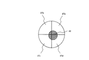
光位置検出素子27は、例えば図6に示すような4分割されたフォトダイオードである。図6は27aから27dまでの4つに分割されたフォトダイオードに光スポット42が当たっている様子を示す。4つのフォトダイオード27aから27dの出力を比較することにより、光スポット42の位置を知ることができる。光位置検出素子27よりの信号は、角度補正情報として制御回路28で演算処理され、光学系10の駆動回路29に駆動信号が出力される。そして駆動回路29により、垂直方向の駆動機構30および水平方向の駆動機構31を動かして、光スポット42の位置が光位置検出素子27の中心に来て、4つのフォトダイオード27aから27dの出力が全て等しくなるような方向に駆動・制御される。
【0006】
光位置検出素子27と発光素子21、光信号検出用の受光素子26は全て光学軸が一致するように位置調整がなされており、光位置検出素子27の中心に光スポット32が当たった状態では、光信号検出用の受光素子26の中心にも光が入射しており、かつ発光素子21よりの光の中心は相手側装置の方向に放射される。
このようにして常に送信光が受信光の方向、即ち相手側装置の方向になるように光軸ずれ補正が行われる。
【0007】
ただし、無線通信という性格上、雨、霧、雪などの気象条件により伝搬する光信号が減衰し、通信が出来なくなる状態があり得る。このような場合、相手側装置の光を検出して行う光軸ずれ補正も出来なくなるので、自動追尾動作も停止させる。この場合、検出される光信号のレベルがある値(しきい値)以下になると、その時点で追尾動作を停止して、その時点での角度駆動機構の位置を保持した状態で、光のレベルが回復して再び追尾動作が可能になるまで待つことになる。
【0008】
【発明が解決しようとする課題】
上記従来例では、装置の角度が変わっても光軸ずれ補正を行うことにより、光ビームの拡がり角を小さくした場合も安定した通信を行うことができるが、雨、霧、雪などの気象条件により伝搬する光信号が減衰し、通信が出来なくなった場合は、前記のように追尾動作を停止して、その時点での角度駆動機構の位置を保持した状態で、光のレベルが回復して再び追尾動作が可能になるまで待つことになる。
【0009】
しかし追尾の停止状態が長くなると、停止している期間中に温度変化などの環境変化などで建物や架台がゆがんで装置の方向が停止前から変化した場合は、天候がかりに回復しても、光ビームがはずれた状態となって、自動追尾動作に入ることも出来ず、通信が復帰することも出来なくなる。
【0010】
さらに光信号のレベルがしきい値以下になり、その時点で追尾動作を停止した時点では、光信号のレベルが低いため光位置検出素子27の出力はノイズの多い、位置精度の悪いものであるから、追尾動作を停止した位置自体も少し本来の位置から外れたものである可能性がある。そのために停止期間中の角度ずれと重なると、更に通信の復帰が不確実なものになる。
【0011】
【課題を解決するための手段】
上記課題を達成するために、本出願にかかわる第一の発明は、
離れた地点間で対向設置されて光ビームにより通信を行う光空間通信装置であって、
相手側装置に光ビームを送出し、また相手側装置からの光ビームを受信するための光学系と、
相手側装置からの光ビームの到来方向を検出するための光位置検出手段と、
前記光位置検出手段からの信号から相手側装置に送出する光ビームの方向角を制御するための制御手段と、
前記制御手段からの指令により相手側装置に送出する光ビームの方向角を駆動する手段とを備えて、自動追尾を行う、光軸ずれ補正機能を持ち、
前記光ビームの方向角を駆動する手段がどの方向に向けているかを検出するための駆動位置検出手段と、前記駆動位置検出手段よりの位置情報を複数個記臆するメモリとを備え、
以下の動作を行うことを特徴とする。
【0012】
▲1▼ 前記光位置検出手段からの信号が既定のレベル以下になると、追尾動作を停止する。
【0013】
▲2▼ 停止時間が所定の値t1を越えると、前記メモリに記臆された複数個の駆動位置情報に示す位置に、所定の時間間隔t2で、記憶された時間の新しいものから古いものの順に順次方向を駆動する。
【0014】
▲3▼ 所定の数の位置情報の示す位置に方向を駆動したのち、最初の方向に戻り停止する。
【0015】
▲4▼ 前記▲2▼と▲3▼を繰り返す。
【0016】
▲5▼ 前記▲2▼から▲3▼の動作の間に前記光位置検出手段からの信号が既定のレベル以上になると、その時点で自動追尾を再開する。
【0017】
また本出願にかかわる第二の発明および第三の発明は、本出願にかかわる第一の発明の光空間通信装置において、前記待ち時間t1あるいは前記時間間隔t2は固定値ではなく、動作の度に所定の値を中心にランダムに値の変わる可変値であることを特徴とする。
【0018】
また本出願にかかわる第四の発明および第五の発明は、本出願にかかわる第一の発明の光空間通信装置において、前記待ち時間t1あるいは前記時間間隔t2は対向する2台の装置で異なった値の固定値であることを特徴とする。
【0019】
【発明の実施の形態】
(第1の実施例)
図1に本願発明による自動追尾により光軸ずれ補正機能を持つ光空間伝送装置を示す。
【0020】
図1において発光素子21よりの光は図5の従来の実施例と同様に偏光ビームスプリッタ22で送受光レンズ23の方向に反射され、送受光レンズ23で、僅かに拡がりを持つほぼ平行の光ビーム24となって相手側装置の方向に送信される。
【0021】
他方相手側装置から送られて来た光は、これも図5の従来の実施例と同様偏光ビームスプリッタ22をそのまま透過し、ビームスプリッタ25に入る。受信光の大部分はビームスプリッタ25で反射し、光信号検出用の受光素子26に入射して、通信用の信号が検出されるが、一部の光はビームスプリッタ25を透過して、光位置検出素子27に入射する。光位置検出素子27よりの信号は、角度補正情報として制御回路28で演算処理され、光学系10の駆動回路29に駆動信号が出力される。そして駆動回路29により、垂直方向の駆動機構30および水平方向の駆動機構31を動かして、光位置検出素子27で検出された相手側装置の方向に送信光ビームが向けられる。
【0022】
また駆動機構30および31の位置(この場合は駆動角度)を検出するための角度センサ33および34を持ち、角度センサ33および34よりの角度情報は、制御回路28に送られ、適当な数値データに変換されたのち制御回路28中にあるメモリ32に記憶される。この角度センサ33および34としては、ロータリーエンコーダ、ポテンショメータ、ホール素子、光学的な位置検出素子などが使える。
【0023】
次に本実施例での光空間通信装置の自動追尾の動作を説明する。
【0024】
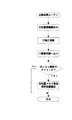
図2は通常時の基本的な動作のフローである。最初は自動追尾に引き込むまで、手動による粗調節の作業が入るが、それが終わると▲1▼の初期化処理の後通常の自動追尾の動作を開始する。先ず▲2▼で光信号が検出されているかどうかを判断し、光信号が検出されていれば自動追尾ルーチンに入る。なおここで言う光信号検出とは、光信号のレベルが、正常に検出可能な規定値以上であるという意味で用いている。
【0025】
図3は自動追尾ルーチンであり、先ず▲5▼で光位置検出素子27から位置情報を読み込み、▲6▼で制御回路28により光軸ずれ補正のための演算処理を行い、▲7▼で駆動回路29から駆動機構30および31を動かして光学系10の方向を駆動する。この後、▲8▼で現在時刻が角度センサ33および34よりの角度情報をメモリ32に書き込むための指定されたタイミングであるかどうかをチェックする。ほとんどの場合はそのタイミングでないので、そのままルーチンを出て▲2▼に戻り、同様に繰り返す。
【0026】
もしその書き込みのタイミングであれば、▲9▼で既にメモリにあるデータを順次新しいメモリ位置に移動して更新した後、空きの出来た最新データを書き込むためのメモリ位置に現在の角度情報を書き込む。その結果メモリの内容は、「現在の角度情報、A1時間前の角度情報、A2時間前の角度情報・・・An時間前の角度情報」というように並ぶ。
【0027】
書き込みのタイミングは設置環境に応じて適当に設定すればよいが、温度変化などによる装置の角度変動が1日周期であることを考えれば、少なくとも現在から24時間以上前までの位置情報をメモリに入れておくことが望ましい。
【0028】
雨、霧、雪などの気象条件により伝搬する光信号が減衰し、▲2▼で光信号が検出されなくなった場合は、その時点での角度情報をメモリに書き込んだ後、▲4▼で自動追尾動作を停止し、図4に示す復帰待ちルーチンに入る。
【0029】
復帰待ちルーチンでは先ず入力待ち状態に入り、(10)で光信号が検出されるまで待つことになる。たいていの場合はそのままの状態で待っていれば、天候が回復して光の減衰が無くなれば光を検出できるようになる。光信号が検出されれば、直ちに復帰待ちルーチンを出て通常の自動追尾ルーチンに移ることができる。しかし「発明が解決しようとする課題」にあるように、停止している期間中に温度変化などの環境変化などで建物や架台がゆがんで装置の方向が変化した場合は、いくら待っても光を検出できなくなる。そこで(12)で予め定められた待ち時間t1を経過すると、サーチ動作のルーチンに移る。
【0030】
サーチ動作のルーチンでは、先ず(13)で現在の自動追尾停止の直前の角度位置から、メモリに記憶された一番近い時点の位置情報で示された位置に角度を駆動する。その新たな位置で(14)で光信号が検出されれば、直ちに復帰待ちルーチンを出て通常の自動追尾ルーチンに移る。しかし(15)での所定時間t2が経っても光信号が検出されない場合は、次の更に以前の時点の位置情報を読んでその位置に角度を駆動して、以下同様に光信号が検出されるようになるまで、時間をさかのぼってサーチを行う。そして(16)で全てのメモリの位置まで動かしても光信号が検出されなかった場合は、まだ光の減衰が大きい状態である可能性が高いと判断して、最初の自動追尾停止の直前の角度位置に戻り、入力待ち状態に再び入る。そして待ち時間t1を経過すると、またサーチ動作のルーチンに移り、これを繰り返す。
【0031】
最初の待ち時間t1はシステムの要求にも依るが、数10分〜数時間程度が適切である。次の位置に移動するまでの間隔t2は、その間に光信号が検出されればよいのであるから、数秒以下程度の短時間で十分である。
【0032】
温度変化などの環境変化は、先に述べたように日周サイクルが主であるから、1日分以上の過去の位置情報を何点か記憶しておけば、かりに自動追尾停止中に装置の角度が変わっても、記憶した位置を順次サーチすることによって復帰できる可能性が非常に高くなる。また記憶した位置情報の大部分は通常の受信状態の良いときのデータであるから、ノイズの少ない精度の高い物であるため、更に復帰の可能性が高くなる(但し気象条件によっては、1日のうち何度も自動追尾を停止することもあり、そのような場合は自動追尾時の位置情報と、自動追尾停止直前の位置情報が混在することになる。またそのような場合は、自動追尾が復帰した直後の位置情報を記憶しておくと有効である)。
【0033】
(第2の実施例)
第二の実施例では上記第一の実施例に於ける入力待ち状態での待ち時間t1と、サーチ動作での次の位置に移るまでの時間間隔t2を、定められた固定値ではなく、定められた時間値を中心としてランダムに長さが変化する、不規則な可変値としたものである。
【0034】
自装置で光信号が検出されないときは、相手側装置でも同様に光信号が検出されない状態であると考えられ、相手側装置も自装置と同じ図4の動作を行っている。その場合、2台の装置で動作の周期が一致してしまうと、場合によってはお互いに相手の装置から逃げあっている状態となり、相手の光を補足することが妨げられる可能性がある。そのために、入力待ち状態での待ち時間t1を固定値とせず、その長さが、擬似的なランダムの数値系列に従って、標準値を中心として不規則に変化する可変値とすれば、互いに動作が一致することなく、ほとんどの場合片側が動いているときは片側が停止しているという状態になり、補足がより確実となる。更にサーチ動作での次の位置に移るまでの時間間隔t2も同様に標準値を中心としてランダムに変化する可変値とすれば、偶然サーチ動作の開始が2台の装置で一致したとしても2台両方が動いている時間確率が小さくなり、補足が更に容易になる。
【0035】
なお、入力待ち状態での待ち時間t1と、サーチ動作での次の位置に移るまでの時間間隔t2を、固定値であるが、対向する2台の装置で値を変えておけば、ランダムに可変するのと近い効果が得られるが、対向する2台の装置の仕様が異なってしまうため、設置や交換時の時間設定の管理が面倒になってくる。
【0036】
【発明の効果】
以上説明したように、本発明によれば、光軸ずれ補正により自動追尾を行う機能を有し、離れた地点間で対向設置されて光ビームにより通信を行う光空間通信装置において、
過去の位置情報を複数点記憶し、光が減衰して自動追尾動作を停止した際に、所定の時間待機しても光が検出されない場合は、時間をさかのぼって記憶した位置を順次サーチすることにより、かりに自動追尾停止中に装置の角度が変わっても、相手装置の光を補足して復帰できる可能性が非常に高くなり、信頼性の高い光空間通信装置を実現できる。
【図面の簡単な説明】
【図1】本発明の実施例
【図2】本発明の実施例における基本動作フロー
【図3】本発明の実施例における自動追尾のフロー
【図4】本発明の実施例における自動追尾停止時の復帰待ちフロー
【図5】従来の実施例
【図6】スポット位置検出素子の例
【符号の説明】
21・・・発光素子
22・・・偏光ビームスプリッタ
26・・・受光素子
27・・・光スポット位置検出素子
28・・・制御回路
29・・・駆動回路
30,31・・・光学系の駆動機構
32・・・メモリ[0001]
TECHNICAL FIELD OF THE INVENTION
The present invention relates to an optical space communication device which is installed opposite to two distant points and transmits an optical signal by a light beam propagating in free space and performs communication, and in particular, an optical axis correction function of a light beam due to an angle shift of the device. It is related to a device having.
[0002]
[Prior art]
In general, an optical space communication device that communicates by propagating a light beam in free space needs to transmit the light beam with a narrow light beam with a minimum divergence angle in order to transmit the light power efficiently. is there. However, if the light beam is narrowed, the light beam is likely to be detached from the partner device due to fluctuations due to wind pressure and vibration of the building or the installation stand, distortion due to temperature fluctuations, and angle fluctuations due to changes in diameter, and stable communication is difficult. For this purpose, as shown in FIG. 5, a device having an optical axis deviation correction function has been devised in which the change in angle is corrected even when the angle of the device changes, so that the light beam always faces the partner device.
[0003]
FIG. 5 shows one side of a pair of opposed devices. In FIG. 5, reference numeral 10 denotes an optical system for transmitting / receiving a light beam. An optical signal transmitted to the other device is emitted from a
[0004]
On the other hand, the light transmitted from the partner device follows the reverse path on the same optical axis as the transmission optical signal from the own device, enters the
[0005]
The light
[0006]
The position of the light
In this manner, the optical axis deviation correction is performed so that the transmission light always becomes the direction of the reception light, that is, the direction of the partner device.
[0007]
However, due to the nature of wireless communication, there may be a state in which an optical signal propagating due to weather conditions such as rain, fog, and snow is attenuated and communication cannot be performed. In such a case, the optical axis deviation correction performed by detecting the light of the partner device cannot be performed, so that the automatic tracking operation is also stopped. In this case, when the level of the detected optical signal falls below a certain value (threshold value), the tracking operation is stopped at that time, and the light level is maintained while the position of the angle driving mechanism at that time is maintained. Is recovered and the tracking operation can be performed again.
[0008]
[Problems to be solved by the invention]
In the above conventional example, even if the angle of the device changes, by performing the optical axis shift correction, stable communication can be performed even when the divergence angle of the light beam is reduced, but the weather condition such as rain, fog, snow, etc. When the optical signal propagating is attenuated and communication becomes impossible, the tracking operation is stopped as described above, and while the position of the angle drive mechanism is held at that time, the light level is recovered. It will wait until the tracking operation becomes possible again.
[0009]
However, if the tracking stop state becomes longer, if the direction of the device changes from before the stop because the building or gantry is distorted due to environmental changes such as temperature change during the stop period, even if it recovers due to the weather, Since the light beam is deviated, the automatic tracking operation cannot be started, and the communication cannot be restored.
[0010]
Further, when the level of the optical signal falls below the threshold value and the tracking operation is stopped at that time, the output of the optical
[0011]
[Means for Solving the Problems]
In order to achieve the above object, the first invention according to the present application is:
An optical space communication device which is installed oppositely between distant points and communicates with a light beam,
An optical system for transmitting the light beam to the other device and receiving the light beam from the other device;
Light position detection means for detecting the arrival direction of the light beam from the other device,
Control means for controlling the direction angle of a light beam to be transmitted to a partner apparatus from a signal from the light position detection means,
A means for driving a direction angle of a light beam to be transmitted to a partner apparatus by a command from the control means, performing an automatic tracking, having an optical axis deviation correction function,
A drive position detecting means for detecting in which direction the means for driving the direction angle of the light beam is directed, and a memory for storing a plurality of pieces of position information from the drive position detecting means,
The following operation is performed.
[0012]
{Circle around (1)} When the signal from the light position detecting means falls below a predetermined level, the tracking operation is stopped.
[0013]
{Circle around (2)} When the stop time exceeds a predetermined value t1, at a predetermined time interval t2, in order from the newest to the oldest stored time, at the positions indicated by the plurality of drive position information stored in the memory. Driving direction sequentially.
[0014]
{Circle around (3)} After driving the direction to the position indicated by the predetermined number of pieces of position information, return to the initial direction and stop.
[0015]
(4) Repeat the above (2) and (3).
[0016]
(5) If the signal from the light position detecting means exceeds a predetermined level during the operations (2) and (3), the automatic tracking is resumed at that point.
[0017]
Further, the second invention and the third invention according to the present application are the optical space communication device according to the first invention according to the present application, wherein the waiting time t1 or the time interval t2 is not a fixed value, It is a variable value whose value changes randomly around a predetermined value.
[0018]
The fourth invention and the fifth invention according to the present application are the optical space communication apparatus according to the first invention according to the present application, wherein the waiting time t1 or the time interval t2 is different between two opposing devices. The value is a fixed value.
[0019]
BEST MODE FOR CARRYING OUT THE INVENTION
(First embodiment)
FIG. 1 shows an optical space transmission apparatus having an optical axis shift correction function by automatic tracking according to the present invention.
[0020]
In FIG. 1, light from a
[0021]
On the other hand, the light sent from the partner device also passes through the
[0022]
Further, it has angle sensors 33 and 34 for detecting the positions of the drive mechanisms 30 and 31 (in this case, the drive angles), and the angle information from the angle sensors 33 and 34 is sent to the control circuit 28 and appropriate numerical data Is stored in the memory 32 in the control circuit 28. As the angle sensors 33 and 34, a rotary encoder, a potentiometer, a Hall element, an optical position detecting element, or the like can be used.
[0023]
Next, the automatic tracking operation of the optical free space communication apparatus according to the present embodiment will be described.
[0024]
FIG. 2 is a flowchart of a basic operation in a normal state. At first, a manual coarse adjustment operation is performed until the automatic tracking is performed. When the operation is completed, the normal automatic tracking operation is started after the initialization process (1). First, in (2), it is determined whether or not an optical signal is detected. If an optical signal is detected, an automatic tracking routine is started. The term "optical signal detection" used here means that the level of an optical signal is equal to or higher than a normally detectable level.
[0025]
FIG. 3 shows an automatic tracking routine. First, position information is read from the optical
[0026]
If it is the write timing, in step (9), the data already in the memory is sequentially moved to a new memory location and updated, and then the current angle information is written to the memory location for writing the latest free data. . As a result, the contents of the memory are arranged as follows: "current angle information, angle information A1 hours ago, angle information A2 hours ago ... angle information An time ago".
[0027]
The write timing may be set appropriately according to the installation environment. However, considering that the angle change of the apparatus due to temperature change is a one-day cycle, at least the position information at least 24 hours before the present time is stored in the memory. It is desirable to keep it.
[0028]
If the optical signal propagating due to weather conditions such as rain, fog, and snow is attenuated and the optical signal is no longer detected in (2), the angle information at that point is written to the memory, and then automatic in (4). The tracking operation is stopped, and the process enters a return waiting routine shown in FIG.
[0029]
In the return wait routine, the process first enters an input wait state, and waits until an optical signal is detected in (10). In most cases, if you wait as it is, you will be able to detect light when the weather recovers and the light is no longer attenuated. If an optical signal is detected, the routine immediately exits the return waiting routine and can proceed to the normal automatic tracking routine. However, as described in "Problems to be Solved by the Invention", if the direction of the device changes due to distortion of the building or gantry due to environmental changes such as temperature changes during the period of suspension, the light Cannot be detected. Then, when the predetermined waiting time t1 has elapsed in (12), the routine proceeds to the routine of the search operation.
[0030]
In the search operation routine, first, in (13), the angle is driven from the current angular position immediately before the automatic tracking stop to the position indicated by the closest position information stored in the memory. If an optical signal is detected at (14) at the new position, the routine immediately exits the return waiting routine and proceeds to the normal automatic tracking routine. However, if the optical signal is not detected even after the lapse of the predetermined time t2 in (15), the position information at the next and earlier time point is read, and the angle is driven to that position. Search backwards until the search is completed. Then, in step (16), if no optical signal is detected even when all the memory locations have been moved, it is determined that there is a high possibility that the light attenuation is still large, and immediately before the first automatic tracking stop is stopped. It returns to the angle position and enters the input waiting state again. Then, after the elapse of the waiting time t1, the processing shifts to the search operation routine again and is repeated.
[0031]
Although the initial waiting time t1 depends on the requirements of the system, it is appropriate to be several tens minutes to several hours. The interval t2 before moving to the next position is sufficient if an optical signal is detected during that time, and a short time of about several seconds or less is sufficient.
[0032]
Environmental changes such as temperature changes are mainly in the diurnal cycle, as described above. Therefore, if several pieces of past position information for one day or more are stored, the device can be automatically stopped during automatic tracking stop. Even if the angle changes, there is a very high possibility that the stored position can be restored by successively searching. In addition, most of the stored position information is data when the normal reception condition is good, and since the data is accurate with little noise, the possibility of return is further increased (however, depending on weather conditions, one day may be required). In such a case, the automatic tracking may be stopped many times, and in such a case, the position information at the time of the automatic tracking and the position information immediately before the stop of the automatic tracking are mixed. It is effective to store the position information immediately after the is returned.)
[0033]
(Second embodiment)
In the second embodiment, the waiting time t1 in the input waiting state and the time interval t2 before moving to the next position in the search operation in the first embodiment are not fixed values but fixed values. It is an irregular variable value whose length changes randomly around the given time value.
[0034]
When the optical signal is not detected in the own device, it is considered that the optical signal is not detected in the other device as well, and the other device performs the same operation as that of the own device in FIG. In this case, if the two devices have the same operation cycle, the devices may run away from each other in some cases, and it may be impossible to supplement the light of the other device. Therefore, if the waiting time t1 in the input waiting state is not set to a fixed value, and the length is set to a variable value that changes irregularly around a standard value in accordance with a pseudo random numerical sequence, the operations of each other are performed. Without a match, most of the time, when one side is moving, one side is stopped, and the supplement is more reliable. Further, if the time interval t2 before moving to the next position in the search operation is also a variable value that randomly changes around the standard value, two units are set even if the start of the search operation coincides with two devices. The probability of the time when both are moving is reduced, making supplementation easier.
[0035]
Note that the waiting time t1 in the input waiting state and the time interval t2 before moving to the next position in the search operation are fixed values, but if the values are changed between two opposing devices, they are randomly set. Although an effect similar to that of changing is obtained, the specifications of the two opposing devices are different, which makes the management of time setting at the time of installation or replacement troublesome.
[0036]
【The invention's effect】
As described above, according to the present invention, in an optical space communication device that has a function of performing automatic tracking by correcting optical axis deviation, and that is installed facing each other between distant points and communicates with a light beam,
When a plurality of pieces of past position information are stored, and when the light is attenuated and the automatic tracking operation is stopped, if no light is detected even after waiting for a predetermined time, the stored position is searched backward and sequentially searched. Accordingly, even if the angle of the apparatus changes during the automatic tracking stop, the possibility of recovering by supplementing the light of the partner apparatus becomes extremely high, and a highly reliable optical space communication apparatus can be realized.
[Brief description of the drawings]
FIG. 1 shows an embodiment of the present invention. FIG. 2 shows a basic operation flow in an embodiment of the present invention. FIG. 3 shows a flow of automatic tracking in an embodiment of the present invention. FIG. 5: Conventional embodiment [FIG. 6] Example of spot position detecting element [Description of symbols]
21 light emitting
Claims (5)
相手側装置に光ビームを送出し、また相手側装置からの光ビームを受信するための光学系と、
相手側装置からの光ビームの到来方向を検出するための光位置検出手段と、
前記光位置検出手段からの信号から相手側装置に送出する光ビームの方向角を制御するための制御手段と、
前記制御手段からの指令により相手側装置に送出する光ビームの方向角を駆動する手段とを備えて、自動追尾を行う、光軸ずれ補正機能を持ち、
前記光ビームの方向角を駆動する手段がどの方向に向けているかを検出するための駆動位置検出手段と、前記駆動位置検出手段よりの位置情報を複数個記臆するメモリとを備え、
以下の動作を行うことを特徴とする光空間通信装置。
▲1▼ 前記光位置検出手段からの信号が既定のレベル以下になると、追尾動作を停止する。
▲2▼ 停止時間が所定の値t1を越えると、前記メモリに記臆された複数個の駆動位置情報に示す位置に、所定の時間間隔t2で、記憶された時間の新しいものから古いものの順に順次方向を駆動する。
▲3▼ 所定の数の位置情報の示す位置に方向を駆動したのち、最初の方向に戻り停止する。
▲4▼ 前記▲2▼と▲3▼を繰り返す。
▲5▼ 前記▲2▼から▲3▼の動作の間に前記光位置検出手段からの信号が既定のレベル以上になると、その時点で自動追尾を再開する。An optical space communication device which is installed oppositely between distant points and communicates with a light beam,
An optical system for transmitting the light beam to the other device and receiving the light beam from the other device;
Light position detection means for detecting the arrival direction of the light beam from the other device,
Control means for controlling the direction angle of a light beam to be transmitted to a partner apparatus from a signal from the light position detection means,
A means for driving a direction angle of a light beam to be transmitted to a partner apparatus by a command from the control means, performing automatic tracking, having an optical axis deviation correction function,
A drive position detecting means for detecting in which direction the means for driving the direction angle of the light beam is directed, and a memory for storing a plurality of pieces of position information from the drive position detecting means,
An optical free-space communication device, which performs the following operation.
{Circle around (1)} When the signal from the light position detecting means falls below a predetermined level, the tracking operation is stopped.
{Circle around (2)} When the stop time exceeds a predetermined value t1, at a predetermined time interval t2, in order from the newest to the oldest stored time, at the positions indicated by the plurality of drive position information stored in the memory. Driving direction sequentially.
{Circle around (3)} After driving the direction to the position indicated by the predetermined number of pieces of position information, return to the initial direction and stop.
(4) Repeat the above (2) and (3).
(5) If the signal from the light position detecting means exceeds a predetermined level during the operations (2) and (3), the automatic tracking is resumed at that point.
Priority Applications (1)
| Application Number | Priority Date | Filing Date | Title |
|---|---|---|---|
| JP2002162254A JP2004015134A (en) | 2002-06-04 | 2002-06-04 | Optical space communication unit |
Applications Claiming Priority (1)
| Application Number | Priority Date | Filing Date | Title |
|---|---|---|---|
| JP2002162254A JP2004015134A (en) | 2002-06-04 | 2002-06-04 | Optical space communication unit |
Publications (2)
| Publication Number | Publication Date |
|---|---|
| JP2004015134A true JP2004015134A (en) | 2004-01-15 |
| JP2004015134A5 JP2004015134A5 (en) | 2005-09-08 |
Family
ID=30431039
Family Applications (1)
| Application Number | Title | Priority Date | Filing Date |
|---|---|---|---|
| JP2002162254A Withdrawn JP2004015134A (en) | 2002-06-04 | 2002-06-04 | Optical space communication unit |
Country Status (1)
| Country | Link |
|---|---|
| JP (1) | JP2004015134A (en) |
Cited By (6)
| Publication number | Priority date | Publication date | Assignee | Title |
|---|---|---|---|---|
| JP2005229277A (en) * | 2004-02-12 | 2005-08-25 | Victor Co Of Japan Ltd | Optical radio transmitter |
| JP2006050029A (en) * | 2004-07-30 | 2006-02-16 | Victor Co Of Japan Ltd | Optical radio transmitter |
| JP2006197078A (en) * | 2005-01-12 | 2006-07-27 | Canon Inc | Optical space communication system |
| JP2007074105A (en) * | 2005-09-05 | 2007-03-22 | Victor Co Of Japan Ltd | Photodetector |
| JP2012060499A (en) * | 2010-09-10 | 2012-03-22 | National Institute Of Information & Communication Technology | Optical wireless communication apparatus |
| RU2770565C1 (en) * | 2021-06-07 | 2022-04-18 | ОБЩЕСТВО С ОГРАНИЧЕННОЙ ОТВЕТСТВЕННОСТЬЮ "КуРэйт" (ООО "КуРэйт") | Method and system for transmitting information via an optical channel between a receiver and a transmitter using beacon laser radiation |
-
2002
- 2002-06-04 JP JP2002162254A patent/JP2004015134A/en not_active Withdrawn
Cited By (10)
| Publication number | Priority date | Publication date | Assignee | Title |
|---|---|---|---|---|
| JP2005229277A (en) * | 2004-02-12 | 2005-08-25 | Victor Co Of Japan Ltd | Optical radio transmitter |
| JP4599847B2 (en) * | 2004-02-12 | 2010-12-15 | 日本ビクター株式会社 | Optical wireless transmission device |
| JP2006050029A (en) * | 2004-07-30 | 2006-02-16 | Victor Co Of Japan Ltd | Optical radio transmitter |
| JP4513057B2 (en) * | 2004-07-30 | 2010-07-28 | 日本ビクター株式会社 | Optical transmission system, optical wireless transmitter, and optical transmission method |
| JP2006197078A (en) * | 2005-01-12 | 2006-07-27 | Canon Inc | Optical space communication system |
| JP4533154B2 (en) * | 2005-01-12 | 2010-09-01 | キヤノン株式会社 | Optical space communication device |
| JP2007074105A (en) * | 2005-09-05 | 2007-03-22 | Victor Co Of Japan Ltd | Photodetector |
| JP4569424B2 (en) * | 2005-09-05 | 2010-10-27 | 日本ビクター株式会社 | Photodetection device and photodetection method |
| JP2012060499A (en) * | 2010-09-10 | 2012-03-22 | National Institute Of Information & Communication Technology | Optical wireless communication apparatus |
| RU2770565C1 (en) * | 2021-06-07 | 2022-04-18 | ОБЩЕСТВО С ОГРАНИЧЕННОЙ ОТВЕТСТВЕННОСТЬЮ "КуРэйт" (ООО "КуРэйт") | Method and system for transmitting information via an optical channel between a receiver and a transmitter using beacon laser radiation |
Similar Documents
| Publication | Publication Date | Title |
|---|---|---|
| WO2016138484A1 (en) | Reliable synchronized delivery on multiple receivers with high accuracy | |
| JP2006067333A (en) | Method and system for data transmission, mobile terminal apparatus and data receiving apparatus | |
| EP2274577A2 (en) | Device for aiding the navigation and guidance of an aircraft, and system comprising such a device | |
| EP0295152A2 (en) | Apparatus for following sun light | |
| JP2004015134A (en) | Optical space communication unit | |
| JP4371910B2 (en) | Optical space transmission equipment | |
| EP1115008A3 (en) | A method for determining reference time error and an electronic device | |
| WO2021067790A1 (en) | Methods for detecting replay attacks in gnss systems and devices thereof | |
| JP2004015135A (en) | Optical space communication unit having direction regulating function | |
| US7076171B2 (en) | Optical space transmitter | |
| CN104272057A (en) | In situ substrate detection for a processing system using infrared detection | |
| JP2005175842A (en) | Photodetector and optical space transmission apparatus | |
| JP4533154B2 (en) | Optical space communication device | |
| JPH08204644A (en) | Optical space transmitter and its optical axis alignment method | |
| JP4506408B2 (en) | Laser distance monitoring system | |
| JP2013190209A (en) | Multipoint laser distance calculation device | |
| CN107111577B (en) | Memory access for dual processor system | |
| JP4743759B2 (en) | Multi-axis photoelectric sensor | |
| JP2007515137A (en) | Laser communication with remote information sources | |
| JP3432008B2 (en) | Optical space communication device | |
| CN102323826A (en) | Automatic basic vector regulation system and automatic basic vector regulation method for quantum communication system | |
| JP3870198B2 (en) | Optical space transmission equipment | |
| JP2005229359A (en) | Optical space communication apparatus | |
| JP2005242710A (en) | Infrared sensor and infrared monitoring system using it | |
| GB2586303A (en) | Apparatus and method of communication between drones |
Legal Events
| Date | Code | Title | Description |
|---|---|---|---|
| A521 | Written amendment |
Free format text: JAPANESE INTERMEDIATE CODE: A523 Effective date: 20050323 |
|
| A621 | Written request for application examination |
Free format text: JAPANESE INTERMEDIATE CODE: A621 Effective date: 20050323 |
|
| A131 | Notification of reasons for refusal |
Free format text: JAPANESE INTERMEDIATE CODE: A131 Effective date: 20060912 |
|
| A521 | Written amendment |
Free format text: JAPANESE INTERMEDIATE CODE: A523 Effective date: 20061109 |
|
| A131 | Notification of reasons for refusal |
Free format text: JAPANESE INTERMEDIATE CODE: A131 Effective date: 20070313 |
|
| A761 | Written withdrawal of application |
Free format text: JAPANESE INTERMEDIATE CODE: A761 Effective date: 20070425 |