JP2004012203A - Optical inclination angle detecting device - Google Patents
Optical inclination angle detecting device Download PDFInfo
- Publication number
- JP2004012203A JP2004012203A JP2002163521A JP2002163521A JP2004012203A JP 2004012203 A JP2004012203 A JP 2004012203A JP 2002163521 A JP2002163521 A JP 2002163521A JP 2002163521 A JP2002163521 A JP 2002163521A JP 2004012203 A JP2004012203 A JP 2004012203A
- Authority
- JP
- Japan
- Prior art keywords
- light
- tilt angle
- boundary
- container
- transparent
- Prior art date
- Legal status (The legal status is an assumption and is not a legal conclusion. Google has not performed a legal analysis and makes no representation as to the accuracy of the status listed.)
- Pending
Links
Images


Abstract
Description
【0001】
【発明の属する技術分野】本発明は、光学式傾斜角検出装置に関するものである。
【0002】
【従来の技術】特開昭60−183516において明細書2頁左段上から10行目に明記されているように、光源と一次元イメージセンサを連通管を挟んで対向させた構造の傾斜角検出装置が開示されている。連通管内には不透明な流体が封入されている。しかしながら封入された流体として不透明な液体を用いた場合には、傾斜方向が判らないこと、および傾斜角検出装置の出力に時間遅れが生じると言う2つの欠点が挙げられる。以下は不透明な流体として不透明な液体を採用し、同時に連通管に空気も封入しているとして説明する。
【0003】
まず、図10に3次元の座標系および角度を定義する。それぞれx、yおよびz軸において、それぞれ40で示すa’、41で示すb’、42で示すc’の切片を有する面44に対し、原点43から面44への垂線104とxy平面がなす角度101をθとする。θのx軸成分を+θx、y軸成分を+θyと定義する。図11に特開昭60−183516に開示された装置の概念図を示す。図11の2で示した座標と角度θ、+θx、+θyの関係は、図10で示した通りとする。図11において一次元イメージセンサ45および46の間の距離61をd1、一次元イメージセンサの位置における空気9と不透明な液体49との境界位置68および69間のz軸方向の距離114をd2とすれば、θy方向の傾斜角は、tan−1(d2/d1)より求めることができる。図11で−θx方向に傾斜したとする。この様子を図12に示す。面光源50から出た光線のうち光線52より下方の光は、不透明液体49により遮蔽され、一次元イメージセンサ45に到達しない。したがって、一次元イメージセンサ45上の光に照射されたピクセルの出力を“1”、照射されないピクセル部分の出力を“0”とすれば、図12における光線52より下のピクセルの出力は“0”となり、一方、光線52以上のピクセルの出力は“1”となる。この一次元イメージセンサの出力の様子を図14(a)に示す。つぎに、図11の傾斜角検出装置が+θx方向に傾斜したとする。この様子を図13に示す。この場合は−θx方向に傾斜した図12の場合と同様に、図13において光線52より下方の光は不透明液体49により遮蔽されるため、光線52より下方のピクセルの出力は“0”、光線52以上のピクセル出力は“1”となる。この場合のピクセル出力の様子を図14(b)に示す。図14(a)および図14(b)において縦軸は、一次元ラインセンサ45のピクセルを上方から数えた場合の位置番号である。横軸は各ピクセルの出力であり“1”もしくは“0”である。図14(a)と図14(b)を比較すると、特開昭60−183516に開示されている傾斜角検出装置が、+θx方向および−θx方向に同じだけ傾斜した場合、一次元イメージセンサ45の出力はいずれも全く同一となり、傾斜方向の違いが判別できない事がわかる。
【0004】
つぎに、特開昭60−183516に開示された傾斜角検出装置の出力の時間遅れの発生について説明する。検出装置が図13に示す状態、すなわち+θx方向に傾いた状態から、+θx方向に0の角度状態に変化したとする。この場合は、非常に薄い不透明液体の膜が連通管の壁面に残存し、光源からの光線を遮る。壁面に残存した不透明液体は、時間とともに下方へ流れついには消失する。これが前記時間遅れの原因である。図16において(a)は+θx方向に傾いている状態の一次元イメージセンサ45の出力を表わす。図15(b)、(c)、(d)は+θx方向の傾きが0の状態で、時間経過とともに液体の状態が変化する様子を示す。図16(a)、(b)、(c)、(d)はそれぞれ、図15(a)、(b)、(c)、(d)の状態における出力である。図15(b)は角度が+θx方向に傾いた状態から0の状態に移って時間経過が少ない状態を表す。連通管の内面に薄い不透明な膜が残存し、その膜により著しく光線がさえぎられ、同じ水平状態でも図16(b)、(c)、(d)で示すように経過に伴い出力が異なる。図15(d)のとき算出される傾斜角の値が望まれる測定値であるため、前述の膜が残存するときにおいて、精度の良い傾斜角測定が不可能であり、図15(d)の状態まで待たねばならない。すなわち傾斜角の変化によっては精度の良い傾斜角の測定に時間を要する場合が生ずる。
【0005】
簡易型の傾斜角検出装置として気泡管を利用したものが多く実用されている。液体と気泡を封入した上部の形状が凸面または凹面になっている気泡管は、その傾斜角によって内部に有する気泡が中心より偏移する。特公平6−48194に記載の傾斜角検出装置では、上方または下方より光線を照射し、光源から気泡管を挟みその対面において受光素子を配置し、気泡管より透過、屈折した光を受光素子で受ける。受光素子で受光量を電子信号に変換し、計算によりその電子信号から気泡管中の気泡偏移情報を得て、重力方向に対する傾斜角を知ることが出来る。特開平7−146142に記載の傾斜角検出装置では、気泡管中の液体に電解液を利用する。傾斜角にしたがって気泡位置が偏移するが、このとき気泡位置の偏移は電極に接触している気泡と電解液の割合の変化を引き起こし、電極間のインピーダンスを変化させる。このインピーダンスを検出することにより傾斜角の算出を行っている。しかし気泡管を利用したものは、温度の変化が引き起こす液体に封入した気泡の膨張収縮とにより誤差が生ずる。特公平6−48194に記載されている傾斜角検出装置でいえば、気泡の大きさが変化することにより受光素子上での気泡影の面積が変化し、したがって受光素子からの電子信号が変化する。また特開平7−146142に記載されている傾斜角検出装置では、電極に接触する気泡の面積が大きくなれば電極間のインピーダンスが変化する。
【0006】
特願平8−59186などに見られるように、傾斜角検出装置として密閉容器に電解液を満たしておき、複数の電極間の傾斜角をインピーダンスの変化により傾斜を検出する方式が存在する。この形式の傾斜角検出装置の持つ欠点としては、電解液の劣化により検出装置の使用期間が限定されることが挙げられる。この形式の傾斜角検出装置に関連する特許には、電解液の長寿命化に関するものもいくつか開示されている。たとえば特願平7−146142では電解液に接触する電極の面積を大きくし、電解液中に流れる電流密度を小さく抑えることにより電気分解の量を減少させている。しかしいずれにしてもこの方式は電気分解などによる電解液の劣化が発生し、検出装置の使用期間を限定してしまう。
【0007】
【発明が解決しようとする課題、課題解決手段、及び効果】
本発明は以上の事情を背景とし、傾斜角測定装置の測定精度の向上、測定に要する時間の短縮、および測定精度が温度の影響を受けない様にすることの少なくとも一つを達成することを目的としたものであり、下記各態様の光学式傾斜角検出装置が得られる。各態様は請求項と同様に、項に区分し各項に(1)から(9)までの番号を付し、必要に応じて他の項の番号を引用する形式で記載する。これはあくまでも本発明の理解を容易にするためであり、本発明最初に記載の技術的特徴およびそれらの組み合わせが、以下の各項に記載のものに限定されると解釈されるべきではない。また1つの項に複数の事項が記載されている場合、それら複数の事項を常に一緒に採用しなければならないわけではなく、また一部の事項のみを取り出して採用することも可能である。
【0008】
(1) 2種類以上の物質を収容した容器を含む被投光部と、その被投光部へ投光する投光部と、投光部より被投光部に投光され被投光部にて光学的影響を受けた光を含む光を受け、それを電子信号に変換し出力する受光部と、受光部からの電子信号を入力し、その電子信号に基づいて傾斜角の計算を行う処理部を含む構成の装置であり、容器中の物質の位置状態より被投光部の重力方向に対する傾斜角を検出する光学式傾斜角検出装置。
傾斜角検出を光学的に行う利点として長期間に渡り使用しても被投光部、受光部の特性劣化の度合いが極めて小さい点が挙げられる。
【0009】
(2) 前記処理部が前記被投光部を構成する容器中に収容されている物質の位置情報のうち、異なる種類の物質間で形成される境界位置の全体もしくは部分を、前記受光部にて検出し前記処理部にて重力方向に対する傾斜角を算出するものである(1)項に記載の光学式傾斜角検出装置。この光学式傾斜角検出装置の被投光部を構成する容器については、密閉であってもなくてもよい。被投光部を構成する密閉容器に2種類以上の物質を収容すると、その物質間で境界面を形成し、その境界面が重力の影響によってその位置が変化し、その境界面の位置の全体または部分を受光部で検出することが可能であれば、容器内の物質が気体、液体、固体どの状態であるものでも可能である。
光学式傾斜角検出装置の構成要素として投光部、被投光部、受光部、処理部の他に、傾斜角の検出特性の向上の目的において、投光部より発せられた光、或いは被投光部において光学的影響を受けた光の性質を限定あるいは変化させるフィルタ、反射板、スリット、レンズ、遮蔽板などを配設することは可能である。このときフィルタ、反射板、スリット、レンズ、遮蔽板などの配設する位置は、受光部から被投光部までの光路中、被投光部から受光部までの光路中、あるいは被投光部の内部とすることが可能である。
被投光部を構成する容器中の異種物質間境界の情報により傾斜角を導き出す利点として、高精度な光学式傾斜角検出装置の実現が安価で容易であることが挙げられる。
【0010】
(3) 前記容器に収容された物質が、透明または半透明の液体と透明または半透明の気体であるか、もしくは複数種類の透明または半透明の液体であり、その容器中に形成される異種物質間境界面の位置の全体もしくは部分を受光部にて検出し、処理部にて傾斜角の算出を行う(2)項に記載の光学式傾斜角検出装置。特開昭60−183516において、容器に透明な気体と不透明な液体を入れ、それらに光線を照射し、密閉容器およびその内部の気体および液体を透過した光線を一次元イメージセンサにより検出し、その光線が有する密閉容器中の液面の情報より傾斜角検出を行う傾斜角検出装置が開示されている。
前記容器中に収容する物質に不透明な物質を用いると、不透明な物質自体が境界の情報を隠蔽することとなる場合が起きる。つまり受光部への光路が限定されるために検出し得る傾斜角の範囲が限定され、あるいは被投光部を構成する容器の形状や投光部、被投光部、受光部の相対位置関係などが限定されてしまうことになる。
例えば図7において三角錐の形状をした透明または半透明の密閉容器29と、その容器29に透明または半透明液体としてアルコールと水の混合液体7と空気9を収容した被投光部に、その容器に投光する投光部としての電界発光装置5から光線を照射し、被投光部を挟んで投光部と対向させた受光部として電荷結合素子の二次元アレイを備えたカメラ19により、被投光部を構成する容器の側面に形成した液体と空気の境界11の位置を検出する傾斜角検出装置において、透明または半透明溶液の代わりに不透明な液体を用いることは適当でない。なぜなら、図7のカメラ19によって得られる被投光部の像の一例である図8における前記異種物質間の境界位置11が図8に示すような状態にあるとき、前記液体が不透明な溶液の場合には、前記異種物質間の境界位置11は得ることが出来ないからである。しかし図7と図8に例を示したとおり、容器中に収容する物質に透明または半透明の溶液と透明または半透明の気体を用い、容器形状が既知であるとすれば、例えば三角錐形状容器29の各々の辺において、空気が占める長さ94、95、96と、液体が占める長さ97、98、99の比によって、少なくとも同一直線状に無い3点の三次元位置が特定されるので、図7に示す座標2の傾斜角θ、φ両方の算出が可能である。
また、例えば図24と図25は、前記被投光部として直方体の透明容器に不透明液体と空気を封入し、側面における境界線の検出をカメラによって行うものであるが、図24の状態と図25の状態を区別することが困難である。これは本願明細書の「従来の技術」の「0003」の項で説明した理由による。一方、図22、図23で示すように前記被投光部として、直方体の透明容器に透明または半透明の液体と透明または半透明の気体として空気を封入し、側面における境界位置88、89の検出をカメラ85で行うとき、カメラ85の合焦位置を変化させることにより、カメラ19に近い面における境界位置88と遠い面における境界位置89を得る事が可能であり、各々の境界線を区別することが可能である。また、近い面と遠い面両方における境界位置の検出とその区別は、図21のように被投光部と受光部の光路中に結像用のレンズを備えることでも可能であるし、また図18と図19のように結像用のレンズを備えていない場合、センサから近い面における境界位置における光量分布のコントラストが、遠い面におけるコントラストよりも大きいため、近い面における境界位置のみの検出が可能である。
この2つの面に生ずる境界線の相互の幅を測定することにより、面に垂直な方向の傾斜を求めることができる。例えば図18において91で示す境界線の高さをpとし、92で示す境界線の高さをqとする。また図18の116で示す容器の一辺の長さをcとする。このとき一次元光電変換素子75にてp、qが測定されると、図18の座標2のθx方向の傾斜角は、
tan−1((p−q)/c)より算出することができる。図18の座標2とθxの関係は図10に示すとおりである。
つまり前記容器に収容する物質を透明または半透明の物質にすることによって、より多くの前記異種物質間境界の情報を得ることができる。
また、前記容器に収容する物質に不透明液体を用いる場合、欠点の一つとして応答時間が遅いことが挙げられる。これは密閉容器内部の液面が下がったとき、不透明な液体が密閉容器の壁面に残り、正しい液面位置まで液体が移動するまで待たねばならず、その結果、被投光部の異種物質間境界位置の検出に長時間必要である事が挙げられる。これは本願明細書の「従来の技術」の「0004」の項で述べたとおりである。
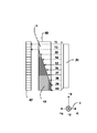
この応答時間の問題を解決するためには、被投光部を構成する容器中に収容する液体を透明、または半透明にすることが有効である。このことにより密閉容器の壁面に残ったわずかな液体の為に著しく光線が遮断され、あるいは、屈折させられることはなくなり、現在の液面より高い位置の壁面に残った微量の液体が原因となって光線がさえぎられ、実際の液面より高い位置を検出することが無いからである。したがって、傾斜角の変動により液面位置が下がった場合でも、壁面に残った微量な液体が現在の液面まで降りてくるまで待つ必要がなくなり、計測に必要な時間が短縮される。図を用いて説明すると、図17のように投光部112として面光源を含み、被投光部として透明または半透明の液体6と透明または半透明の気体として空気9を収容した透明または半透明の直方体容器111を含み、受光部として一次元光電変換素子アレイ75、76を含み、被投光部をはさみ、受光部と被投光部を対向する形で配設されている構成の傾斜角検出装置を考える。ここで図17の2で示す座標と傾斜角θx、θyの関係は、図10に示した通りとする。受光部75、76によって、容器内壁の受光部に近い面における異種物質間の境界面107の境界位置77、78をそれぞれ検出する。ここで異種物質間の境界位置77、78の容器底面からの高さをそれぞれa、bとし、一次元光電変換素子アレイ75、76の中心間距離をcとする。検出したその異種物質間の境界位置の高さと、一次元光電変換素子アレイの中心間距離によってθyは、
tan−1((a−b)/c)から求められる。ここでこの機器構成において図19に示す状態、すなわち+x方向に+θx傾いた状態から、図20に示す状態、すなわち+x方向に0の状態に変化したとする。この場合、図26(b)、(c)、(d)において示すように、透明または半透明の液体の膜が容器の壁面に残存し、時間とともに下方へ流れついには消失する。図27の(a)、(b)、(c)、(d)はそれぞれ、図26の(a)、(b)、(c)、(d)の状態のときの、図26の一次元光電変換素子アレイ87の出力を示している。この膜が残存する状態、すなわち図26の(b)、(c)の状態においても、光量分布から図26(b)、(c)の73で示した境界位置の検出が可能であり、したがって図26(d)の状態となるまで待つことなくθx方向の傾斜角の算出は可能である。
【0011】
(4) 前記容器に収容された2つの物質の境界が、重力方向に垂直な平面あるいは平面形状部分を含む形状となる構造の前記被投光部を含み、前記容器中の前記異種物質間境界面の方向に基づいて傾斜角の算出を行うものである(2)項に記載の光学式傾斜角検出装置。(請求項1)
この項を含むいかなる項の記述においても、前記異種物質間境界の形状を平面と記述した場合、前記異種物質間境界の前記容器の内壁と接する部分が、表面張力などにより平面から僅かに外れる場合もあるが、その場合も境界が平面を成すものと見なすものとする。
この場合、通常表面張力により境界線が上下2本現れる。こうしたときは上下2本の境界線の中間位置を境界とする等の処理を行う。また、その線の像がフォーカスの影響で太い線になることもある。この場合はその線の中心を採用する、或いは線の上端、下端等を使用することもある。
光学式傾斜角検出装置として気泡管を利用したものが多く実用されている。液体と気泡を封入し、上部の形状が凸面または凹面になっている気泡管は、その傾斜角に応じて内部に有する気泡が中心より偏移する。特公平6−48194では、上方または下方の光源より光線を照射し、気泡管を間に挟んで光源と対向する受光素子に、気泡管より透過し屈折させられた光を受けさせる。受光素子で受光量を電子信号に変換し、計算によりその電子信号から気泡管中の気泡偏移情報を得て、重力方向に対する傾斜角を知ることが出来る。特開平7−146142では気泡管中の液体を電解液とし、気泡管中の気泡の偏移が、電極に接触している気泡と電解液の割合に対応した電極間のインピーダンス変化として現れるので、この情報より傾斜角の算出を行っている。しかし気泡管を利用したものは、温度の変化により液体に囲まれた気泡が膨張収縮することにより誤差が生ずる。
本発明においては、被投光部を形成する容器に封入する2つの物質で形成する境界面の傾きより傾斜角を算出するので、温度変化などにより物質境界面の位置が変化しても誤差要因とならない。
一例をあげて説明すると、図17において傾斜角度が同じ状態において、108で示す異種物質間境界位置を、物質の膨張収縮により107で示す異種物質間境界位置から変化した後の境界面とする。一次元光電変換素子アレイ75、76におけるこの異種物質間境界位置の移動距離は同じ値αとなる。ここで75、76で検出される移動前の107で示す異種物質間境界位置の容器底面からの高さをそれぞれe、fとする。一次元光電変換素子アレイ75、76の中心間距離81をgとする。膨張収縮によって移動した状態で傾斜角を算出してもθy方向の傾斜角は、
tan−1((e+α−f−α)/g)
=tan−1((e−f)/g)より、移動前と同じ値tan−1((e−f)/g)が得られることになる。
被投光部を構成する容器中の異なる種類の物質間の境界位置情報により傾斜角を検出する場合で、被投光部を構成する容器中の異なる物質間の境界が、重力方向に対して垂直な平面に近い形状、あるいは重力方向に対して垂直な平面に近い形状の部分を含み、その重力方向に対して垂直な平面に近い形状から傾斜角の検出を行う場合、平行でない2線分、または1つの線分とその線分を含む直線上にない1点、または同一直線上にない3点を検出することにより2方向の傾斜角を知ることができる。
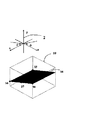
たとえば図を用いて説明すると、図9の面34上の3点を検出して面34の傾斜角を求める場合、点35の位置、点36の位置、点37の位置を検出すればφ方向、θ方向の傾斜角が算出可能となる。ここでφ方向とはz軸周りの傾斜角で、θ方向とはx軸周りの傾斜角である。点36の位置、点37の位置、点38の位置を検出するのみでは、φ方向の傾斜角算出可能でθ方向の傾斜角の算出が不可能である。図9の平面34上の1つの線分位置と1つの点位置を検出し、平面34の傾斜角を求める場合、点36と点37を結ぶ線分位置と、点35の位置を検出すればφ方向、θ方向の傾斜角が算出可能となる。また、例えば点36と点37を結ぶ線分位置と点38の位置を検出するとき、φ方向のみの傾斜角が算出可能であり、θ方向の傾斜角算出は不可能である。図9の平面34上の2つの線分位置を検出し、平面34の傾斜角を求める場合、例えば点35と点36を結ぶ線分位置と、点36と点37を結ぶ線分位置を検出すれば、φ方向、θ方向の傾斜角が算出可能となる。また、例えば点36と点37を結ぶ線分位置と、点37と点38を結ぶ線分位置のみの検出であれば、φ方向の傾斜角が算出可能であり、θ方向の傾斜角算出は不可能である。一般的に言えば、少なくともある1つの平面上の平行でない2線分、または1つの線分とその線分を含む直線上にない1点、または一直線上にない3点が得られれば、その平面を表す式ax+by+cz=dが求められる。そしてその式が求められれば図9における傾斜角φ、θは、
φ=tan−1(−a/b)、
θ=tan−1(−c/b)より求められる。
以上の例からも見られるように、平行でない2線分、または1つの線分とその線分を含む直線上にない1点、または一直線上にない3点を含む情報が得られるように、この項を含む以下の項を組み合わせることにより独立2方向の傾斜角の検出が可能となる。
【0012】
(5) 前記受光部が光電変換素子の一次元アレイを含み、その受光部により前記境界面の位置を2点以上の位置で検出し、前記処理部がそれら2点以上の位置の相対位置関係より前記平面状の境界面の傾斜角を算出するものである(4)項に記載の光学式傾斜角検出装置。(請求項2)
本項記載の光学式傾斜角検出装置の利点として、前記異種物質間境界のうち重力に対して垂直な平面をなす部分の位置を2点以上検出し、その点間を結んだ線分の傾斜を算出することにより傾斜角を求める為、温度変化などによる物質の膨張収縮に伴う、前記容器中に収容した物質の体積比変化を原因とする液面の高さの変化が、検出精度に影響することはない。
前記容器に収容される物質が、透明または半透明の気体と透明または半透明液体の組み合わせであるか、もしくは複数種類の透明または半透明の液体の組み合わせであるので、光電変換素子の一次元アレイにより、前記容器内壁における前記異種物質間の境界面位置付近の光量分布を得ることが可能で、この光量分布より前記異種物質間の境界面位置の検出が光電変換素子アレイのサブピクセル精度で可能であり、高精度な傾斜角検出が可能となる。また光電変換素子の一次元アレイは、小型軽量であることも大きな利点で、小型で高精度な傾斜角検出装置の実現に寄与するものである。
また、本項記載の装置において、前記異種物質間境界のうち重力方向に垂直な平面をなす部分の同一直線上にない3点位置が検出された場合、前記異種物質間境界のうち重力方向に垂直な平面をなす部分の位置を特定することが出来る。したがって2方向の傾斜角を検出することが可能となる。
【0013】
(6) 前記受光部が光電変換素子の二次元アレイを含み、その受光部により前記異種物質間境界平面の位置の全体または部分を検出し、その境界平面位置より傾斜角を算出する(3)項ないし(4)項いずれかに記載の光学式傾斜角検出装置。
従来、気泡管中の気泡位置あるいは凹型容器中の球形振り子位置を検出することにより、傾斜角を算出する傾斜角検出装置において、4つの光電変換素子を平面状に田の字形に配置した光電変換素子二次元アレイを用い、その4つの光電変換素子からの信号を比較し、光量の比較をすることによって傾斜角の検出を行う形式の傾斜角検出装置が知られている。この形式の場合、4つの光電変換素子間における光電変換特性のばらつきや経年変化が誤差原因となる。すなわち、同じ光量でも変換した信号に差が生じ、この信号の差が傾斜角検出の誤差になるのであり、光電変換素子の光電変換特性校正の重要性が高くなる。この光電変換素子一つずつに校正用の光源をつけ、光電変換特性の校正を容易にしたものも存在するが、光源自体もばらつきがあるため問題を完全に解決し得るわけではない。本発明においては光電変換素子の二次元アレイは、被投光部中の物質間境界位置を検出するために用い、その物質間境界位置の傾斜により傾斜角の検出を行う。そのため、光電変換素子の変換特性における多少のばらつきや経年変化が誤差要因となることはない。前記容器に収容される物質が、透明または半透明の気体と透明または半透明液体の組み合わせであるか、もしくは複数種類の透明または半透明の液体の組み合わせであるので、光電変換素子の二次元アレイにより前記容器内壁における前記異種物質間の境界面位置付近の光量分布を得ることが可能で、この光量分布より前記異種物質間の境界面位置の検出が光電変換素子アレイのサブピクセル精度で可能であり、高精度な傾斜角検出が可能となる。
【0014】
(7) 前記容器に収容された2つの物質の境界が重力方向に垂直な平面をなし、または重力方向に垂直な平面を含み、前記受光部が二次元の光電変換素子アレイを含み、前記処理部が前記平面と容器内面との境界位置の全体または部分を検出する。そしてその検出した境界位置に対し直線近似を行う。その検出した境界位置に対しての直線近似で得られた直線の傾きにより傾斜角を検出するものである(4)項記載の光学式傾斜角検出装置。(請求項3)
前記容器に収容される物質が、透明または半透明の気体と透明または半透明液体の組み合わせであるか、もしくは複数種類の透明または半透明の液体の組み合わせであるので、光電変換素子の二次元アレイにより前記容器内壁における前記異種物質間の境界位置付近の光量分布を得ることができる。この光量分布により異種物質間の境界位置を得ることが可能である。検出された前記容器内面における異種物質間境界位置に対して直線近似を行い、その直線の傾きより傾斜角の算出を行う。前記異種物質間境界位置の傾斜自体を計測するため、温度変化などによる物質の膨張収縮に伴う体積比変化による前記異種物質間境界位置の高さの変化が、傾斜角計測誤差を生じせしめることは無い。このことの原理的な説明は(4)項に記載した内容と同様である。
【0015】
(8) 前記受光部において、前記被投光部を構成する前記容器の三次元形状の全体または部分と、前記異種物質間の三次元位置の全体または部分を検出し、その両者より傾斜角の算出を行う(2)、(3)、(4)、(5)、(6)、(7)項いずれかに記載の光学式傾斜角検出装置。(請求項4)
測定時における前記被投光部を構成する容器と境界面の相対位置関係を検出することになり、振動、衝撃などにより前記投光部、被投光部、受光部の相対位置関係の移動が生じても精度良く計測することが可能となる。したがって振動、衝撃などに対して頑強な傾斜角測定が可能である。
例えば図4を用いて説明する。投光部を構成する電界発光装置5、被投光部を構成する内部に透明または半透明の溶液と空気を収容した三角柱透明容器23、そして受光部を構成するカメラ19を含む構成の傾斜角検出装置を挙げる。投光部、被投光部、受光部の相対位置関係が固定されているとする。カメラ19は二次元撮像素子を備え、被投光部の二次元像を撮像することが出来るものである。被投光部を構成する容器の形状は直角三角柱で、その3つの側面のうち同じ形の2つの側面は一辺がd3の正方形であり、測定時において形状は既知である。ここで受光部の投光部、被投光部に対する相対位置関係に変動が加わり、投光部、被投光部間の相対位置関係に変動が無いときを例として考える。
カメラ19により得られる像から得られる異種物質間境界の位置のみより傾斜角を算出する場合、算出された傾斜角の値には誤差が当然含まれる。これに対してカメラ19により容器の外形形状と異種物質間境界の双方の位置と形状を得ることにより、算出する傾斜角の値に含まれる誤差を小さくすることが出来る。例えば図5は、図4の傾斜角検出装置においてカメラ19によって得られた被投光部の像である。図5に示す像によって、各頂点62、63、64、65、66、67からの異種物質間境界までの距離94をs、95をt、96をu、97をp、98をq、99をrとする。このとき下方側に混合液体7、上方に空気9があるものとする。図5により、sとp、tとq、uとrの比を得ることができ、一辺がd3であることとあわせてs、t、u、p、q、rが算出される。そして図5の2に示す座標のθ、φを、
θ=tan−1((−r+q)/d3)、
φ=tan−1((−p+q)/d3)より算出されるのである。つまり相対位置関係の変動後でも、像から異種物質間境界11、容器の外形形状21を得ることができ、像から得られる頂点62、63、64、65、66、67と実際の容器の頂点の対応が明らかであれば、少なくとも被投光部に対する傾斜角計測が可能となる。これは投光部、被投光部、受光部三者の相対位置関係の校正などにも応用可能である。
【0016】
(9) 前記処理部において、時間情報を伴う前記異種物質間の境界位置の情報より波動などの乱れを除去して、前記異種物質間境界の傾きより傾斜角の算出を行う(2)項ないし(3)、(4)、(5)、(6)、(7)、(8)項いずれかに記載の光学式傾斜角検出装置。(請求項5)
傾斜角の測定時において、前記容器中の異種物質間境界面に波動が残っている状態でも、傾斜角の算出を行うことができることから、迅速な傾斜角計測あるいは頻繁に傾斜角が変化する条件での傾斜角計測に有効である。
【0017】
【発明の実施の形態】
図面を用いて本発明の実施の形態を説明する。
【0018】
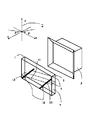
(実施形態1) 図1において示すように、直方体形状の透明な密閉容器1にアルコールと水の混合液体7と空気9を封入する。このとき直方体透明容器1の内部では、混合液体7と空気9の境界面が容器内で平面を成す様に封入する。この平面は重力方向に対して垂直を成す。直方体密閉容器1のある1つの側面に対して外側から電界発光装置5で垂直に光線を照射する。その光線を照射した面と対向する面の外側に、電荷結合素子の一次元アレイ3を配設する。2つの電荷結合素子の一次元アレイ3それぞれによって境界面の線11の位置を検出し、その検出位置を結ぶ線分の傾きを算出することにより、図1の2で示す座標中のφ方向の傾斜角の算出を行う。この場合、液体と密閉容器の間の表面張力により境界線が2本になったり、フォーカスがぼやけた場合は太い線になるが、2本の線の中心を取ったり、太い線の中心を用いる。もちろん、2本の境界線の上または下の線を用いる、あるいはフォーカスがぼやけて太い線になった場合、線の上端または下端等を用いることが可能である。以下の実施例についても、必要な場合は同様の処理を行うことが可能である。なお傾斜角の計測にあたり、被投光部を構成する容器の形状とその容器内部に収容する物質の量など幾何学的な条件を考慮に入れる、あるいは容器内部の物質の光透過率、光屈折率など光学的な性質を考慮に入れれば、ある傾斜角度値とその傾斜角度値に対して180度の差異のある傾斜角度との区別が可能である。これは以下の実施形態についても同様である。
【0019】
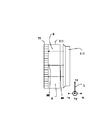
(実施形態2) 図2において、直方体形状の透明な密閉容器1にアルコールと水の混合液体7と空気9を封入し、容器1の内部では混合液体7と空気9の境界面が容器内で平面を成すようにする。この平面は重力方向に対して垂直である。電界発光装置5で透明容器の1つの側面に対して外側より垂直に投光を行い、その面に対向する側面に電荷結合素子の二次元アレイ17を外側に配置する。電界発光装置5と電荷結合素子の二次元アレイ17は対向する形となる。
ここで透明容器側面のうち、電荷結合素子の二次元アレイ17が配置されている側面の内壁におけるアルコール液体7と空気9の境界面の位置11の一部を、電荷結合素子の二次元アレイ17により検出する。透明または半透明の直方体密閉容器1中のアルコール液体7と空気9の境界位置11の部分の付近の光量分布を検出し、サブピクセル精度でアルコール液体7と空気9の境界位置11の部分を算出する。その算出した境界位置に対して直線近似をおこない、その直線の傾きより図2の2で示した座標のφ方向傾斜角の算出を行う。
【0020】
(実施形態3) 図3に示すように、透明または半透明の直方体形状密閉容器1にアルコールと水の混合液体7と空気9を封入し、容器内部でアルコール液体7と空気9の境界面11が容器内で平面を成す構造とする。その直方体容器のある1つの側面に対して外側より電界発光装置5で平行光線を垂直に照射する。その電界発光装置5に対して直方体透明容器1をはさみ対向する位置にカメラ19を配設する。カメラ19は二次元撮像素子アレイを備え、二次元画像の撮像が可能であるものである。
直方体透明容器1の側面の形状と直方体中に封入した混合液体7と空気9の境界面のうち、容器内壁における境界位置11およびその付近を、カメラ19により検出する。このとき合焦位置を変化させることにより、カメラ19から近い面における境界位置32と、カメラ19から遠い面における境界位置33を得る事ができる。カメラによって焦点を合わせた透明容器側面について、その側面の内壁におけるアルコールと水の混合液体7と空気9の境界面位置32または33付近の光量分布を、カメラ19により検出する。その検出した光量分布より前記境界位置32または33を算出する。そして算出された境界位置32または33に対して直線近似を行い、その直線の傾きより図3の2で示す座標のφ方向傾斜角の算出を行う。また近い面における直線の高さと遠い面における直線の高さの差を用いることにより、図3の2で示す座標のθ方向傾斜角の算出も可能である。カメラ19を利用することにより容器の形状を得ることが可能である。したがって傾斜角測定時において、透明または半透明の直方体密閉容器1とカメラ19の相対位置関係の校正を行うことが可能である。
【0021】
(実施形態4) 図4で示すように、透明または半透明の直角三角柱形状密閉容器23にアルコールと水の混合液体7と空気9を封入し、容器内部で混合液体と空気の境界面が容器内で平面を成す構造とする。その透明または半透明の直角三角柱形状密閉容器23の直角をなす2つの側面を見渡すことのできる位置にカメラ19を配設する。このカメラ19に対して直角三角柱形状透明容器23をはさみ対向する位置に電界発光装置5を配設し、これをもって平行光線を直角三角柱形状密閉容器23に照射する。その電界発光装置にカメラ19は二次元撮像素子アレイを備え、二次元画像の撮像が可能であるものである。このときすなわちカメラ19は、直角三角柱形状容器23の側面のうち直角を成す2面を撮像可能な位置にある。
図5に示すようにカメラ19によって、直角三角柱密閉容器の側面のうち近い方の面の形状と、直角三角柱容器中に封入したアルコール液体7と空気9の境界面のうち容器内壁における境界位置11を検出する。その結果、図5における直角三角柱形状容器の容器内壁におけるアルコール液体7と空気9の境界位置11と交差する形となる三辺の各々について、底面から境界位置までの距離97、98、99と、上面から境界位置までの距離94、95、96の長さの比を検出することができる。なお図5においては上側に空気が、下側には液体が存在する場合を示す。容器の形状が既知であるので、検出した各々の面について境界線11と容器側面の形状より境界線11の傾斜角を算出することが可能である。
【0022】
(実施形態5) 図6で示すように、三角錐形状の透明な密閉容器29に、アルコールと水の混合液体7と空気9を封入し、容器内部で混合液体7と空気9の境界面11が、容器内で平面を成す構造とする。その三角錐形状容器29の底面に対して、外側より垂直に電界発光装置5で光線を照射する。その底面を除く3つの側面に電荷結合素子の一次元アレイ3を各々一つずつ配置する。電荷結合素子の一次元アレイ3すべてにおいて、混合液体7と空気9の境界位置11が検出される位置にあるとき、混合溶液7と空気9の境界位置のうち同一直線上にない3点がサブピクセル精度で検出され、図6の2で示した座標のφ、θ方向の傾斜角の算出が可能である。
【0023】
(実施形態6) 図7に示す透明または半透明の三角錐密閉容器29に、アルコールと水の混合液体7と空気9を封入する。前記三角錐密閉容器29の内部では、混合液体7と空気9の境界面が容器内で平面を成している。この平面は重力方向に対して垂直である。前記三角錐密閉容器29に対して、底面外側から電界発光装置5で投光する。その電界発光装置5に対して、三角錘形状容器29をはさみ対向する位置にカメラ19を配設する。カメラ19は二次元撮像素子アレイを備え、二次元画像の撮像が可能であるものである。このときカメラ19は三角錐形状透明容器29の側面3面を見渡す位置にある。カメラ19と電界発光装置5と三角錐形状透明容器29の相対位置関係は固定されている。傾斜角計測時においては、カメラ19と電界発光装置と容器の相対位置関係と、三角錐形状透明容器29の形状は既知である。容器内壁において生成される混合液体と空気の境界面の位置11を、カメラ19によってサブピクセル精度で検出し、その検出位置に対して直線近似をおこなう。三角錐形状容器29の形状は既知であるので、その直線は図8の三角錘形状容器の外形輪郭70との相対位置関係から三次元位置が算出される。したがって図7の2で示した座標のφ、θ方向の傾斜角の算出が可能である。
【図面の簡単な説明】
【図1】第1の実施形態を示す構成図
【図2】第2の実施形態を示す構成図
【図3】第3の実施形態を示す構成図
【図4】第4の実施形態を示す構成図
【図5】第4の実施形態においてカメラにより撮像された像
【図6】第5の実施形態を示す構成図
【図7】第6の実施形態を示す構成図
【図8】第6の実施形態においてカメラにより撮像された像
【図9】2方向の傾斜角が測定可能な機器構成を説明するための図
【図10】ある座標における面と傾斜角の関係を示す図
【図11】不透明な液体を用いた光学式傾斜角検出装置の一例
【図12】図11で示す光学式傾斜角検出装置の傾斜角計測の例
【図13】図11で示す光学式傾斜角検出装置の傾斜角計測の例
【図14】図12、図13における一次元イメージセンサの出力例
【図15】図11で示す光学式傾斜角検出装置の傾斜角計測の例
【図16】図15における一次元イメージセンサの出力例
【図17】本発明の構成の一例
【図18】図17で示す光学式傾斜角検出装置の傾斜角計測の例
【図19】図17で示す光学式傾斜角検出装置の傾斜角計測の例
【図20】図17で示す光学式傾斜角検出装置の傾斜角計測の例
【図21】本発明の構成の一例
【図22】本発明の構成の一例
【図23】本発明の構成の一例
【図24】不透明な液体を用いた光学式傾斜角検出装置の一例
【図25】不透明な液体を用いた光学式傾斜角検出装置の一例
【図26】図17で示す光学式傾斜角検出装置の傾斜角計測の例
【図27】図26における一次元光電変換素子アレイの出力例
【符号の簡単な説明】
1 直方体形状の透明密閉容器
2 説明のために設定した座標軸
3 電荷結合素子の一次元アレイ
5 電界発光装置
6 透明または半透明の溶液
7 アルコールと水の混合液体
9 空気
11 密閉容器内壁で形成する混合液体と空気の境界面の線
13 電荷結合素子の一次元アレイによって検出された混合液体と空気の境界線の位置の一つ
14 電荷結合素子の一次元アレイによって検出された混合液体と空気の境界線の位置の一つ
15 電荷結合素子の一次元アレイによって検出された混合液体と空気の境界線の位置の一つ
16 電荷結合素子の取り付け角度
17 電荷結合素子の二次元アレイ
19 電荷結合素子の二次元アレイを備えたカメラ
21 透明密閉容器の外形輪郭
23 直角三角柱形状の透明密閉容器
29 三角錐形状の透明密閉容器
32 カメラから近い面における境界位置
33 カメラから遠い面における境界位置
34 ax+by+cz=dで表される面
35 説明のための点位置の一つ
36 説明のための点位置の一つ
37 説明のための点位置の一つ
38 説明のための点位置の一つ
39 各辺が図の2で示す座標の座標軸に平行である、説明のために設けた仮想的な直方体
40 x軸の切片a’
41 y軸の切片b’
42 z軸の切片c’
43 原点
44 面
45 一次元イメージセンサ
46 一次元イメージセンサ
48 連通管
49 不透明な液体
50 面光源
51 面光源から照射された光線
52 面光源から照射された光線
53 面光源から照射された光線
54 面光源から照射された光線
55 面光源から照射された光線
56 面光源から照射された光線
57 面光源から照射された光線
58 面光源から照射された光線
59 面光源から照射された光線
60 面光源から照射された光線
61 一次元イメージセンサの中心間距離
62 三角柱形状の透明容器の頂点の一つ
63 三角柱形状の透明容器の頂点の一つ
64 三角柱形状の透明容器の頂点の一つ
65 三角柱形状の透明容器の頂点の一つ
66 三角柱形状の透明容器の頂点の一つ
67 三角柱形状の透明容器の頂点の一つ
68 一次元イメージセンサによって検出された境界位置
69 一次元イメージセンサによって検出された境界位置
70 透明容器の外形輪郭の像
71 容器内壁で形成される混合液体と空気の境界面の線の像
73 一次元光電変換素子アレイによる検出境界位置
75 一次元光電変換素子アレイ
76 一次元光電変換素子アレイ
77 一次元光電変換素子アレイ75によって検出された境界位置
78 一次元光電変換素子アレイ76によって検出された境界位置
79 傾斜角θy
80 傾斜角θx
81 一次元光電変換素子アレイの中心間距離
82 面光源から照射された光線
83 面光源から照射された光線
84 面光源から照射された光線
85 カメラ
86 レンズ
87 一次元光変換電素子アレイ
88 一次元光電変換素子アレイに近い面における境界位置
89 一次元光電変換素子アレイから遠い面における境界位置
91 一次元光電変換素子アレイに近い面における底面から境界までの距離
92 一次元光電変換素子アレイから遠い面における底面から境界までの距離
94 ある一辺における空気が占める長さs
95 ある一辺における空気が占める長さt
96 ある一辺における空気が占める長さu
97 ある一辺における混合液体が占める長さp
98 ある一辺における混合液体が占める長さq
99 ある一辺における混合液体が占める長さr
100 角度φ
101 角度θ
102 角度θx
103 角度θy
105 垂線−θx
106 角度−θy
107 容器内壁で形成される透明または半透明の液体と空気の境界面の線
108 移動後の容器内壁で形成される透明または半透明の液体と空気の境界面の線
109 境界面の移動距離
110 境界面の移動距離
111 透明または半透明の容器
112 投光部
114 一次元イメージセンサ68で検出した境界位置と一次元イメージセンサ69で検出した境界位置のz方向の距離
115 一次元光電変換素子アレイ75で検出した境界位置と、一次元光電変換素子アレイ76で検出した境界位置のz方向の距離
116 容器のある一辺の長さ[0001]
BACKGROUND OF THE
[0002]
2. Description of the Related Art In Japanese Patent Application Laid-Open No. 60-183516, as specified in the tenth line from the upper left of
[0003]
First, a three-dimensional coordinate system and an angle are defined in FIG. In the x, y, and z axes, respectively, a
[0004]
Next, the occurrence of a time delay in the output of the tilt angle detection device disclosed in Japanese Patent Application Laid-Open No. 60-183516 will be described. It is assumed that the detection device has changed from the state shown in FIG. 13, that is, the state inclined in the + θx direction, to an angle state of 0 in the + θx direction. In this case, a very thin film of the opaque liquid remains on the wall surface of the communication tube, and blocks light from the light source. The opaque liquid remaining on the wall flows downward with time and eventually disappears. This is the cause of the time delay. FIG. 16A shows the output of the one-
[0005]
As a simple type of tilt angle detecting device, a device using a bubble tube has been widely used. In a bubble tube in which a liquid and bubbles are sealed, the upper portion of the bubble tube has a convex surface or a concave surface, and bubbles contained therein are shifted from the center by the inclination angle. In the tilt angle detection device described in Japanese Patent Publication No. 6-48194, a light beam is emitted from above or below, a light receiving element is arranged on the opposite side of the bubble tube from the light source, and light transmitted and refracted from the bubble tube is received by the light receiving device. receive. The amount of light received is converted into an electronic signal by the light receiving element, and information on the shift of the bubbles in the bubble tube is obtained from the electronic signal by calculation, whereby the inclination angle with respect to the direction of gravity can be known. In the tilt angle detecting device described in Japanese Patent Application Laid-Open No. H07-146142, an electrolytic solution is used as the liquid in the bubble tube. The bubble position shifts according to the tilt angle. At this time, the shift of the bubble position causes a change in the ratio of the bubble and the electrolyte contacting the electrodes, and changes the impedance between the electrodes. The inclination angle is calculated by detecting the impedance. However, in the case of using a bubble tube, an error occurs due to expansion and contraction of bubbles sealed in a liquid caused by a change in temperature. In the case of the tilt angle detection device described in Japanese Patent Publication No. 6-48194, the area of the bubble shadow on the light receiving element changes due to the change in the size of the bubble, and therefore, the electronic signal from the light receiving element changes. . Further, in the tilt angle detecting device described in Japanese Patent Application Laid-Open No. H07-146142, the impedance between the electrodes changes when the area of the bubble contacting the electrodes increases.
[0006]
As disclosed in Japanese Patent Application No. 8-59186, there is a method for detecting a tilt angle between a plurality of electrodes by changing an impedance by filling a closed container with an electrolytic solution as a tilt angle detecting device. A disadvantage of this type of tilt angle detection device is that the use period of the detection device is limited due to deterioration of the electrolytic solution. Patents relating to this type of tilt angle detecting device also disclose several patents relating to prolonging the life of an electrolytic solution. For example, in Japanese Patent Application No. 7-146142, the amount of electrolysis is reduced by enlarging the area of the electrode in contact with the electrolyte and suppressing the current density flowing in the electrolyte. However, in any case, this method causes deterioration of the electrolytic solution due to electrolysis or the like, and limits the use period of the detection device.
[0007]
Problems to be Solved by the Invention, Means for Solving Problems, and Effects
The present invention is based on the above circumstances, and achieves at least one of improvement of measurement accuracy of a tilt angle measuring device, reduction of time required for measurement, and prevention of measurement accuracy from being affected by temperature. The objective is to obtain an optical tilt angle detecting device of each of the following embodiments. As in the claims, each aspect is divided into sections, and each section is numbered from (1) to (9), and if necessary, is described in a form in which the numbers of other sections are cited. This is merely for the purpose of facilitating the understanding of the present invention, and the technical features and combinations thereof described first in the present invention should not be construed as being limited to those described in the following sections. Further, when a plurality of items are described in one section, it is not always necessary to adopt the plurality of items together, and it is also possible to take out and adopt only some of the items.
[0008]
(1) A light projecting unit including a container containing two or more types of substances, a light projecting unit that projects light to the projecting unit, and a projecting unit that projects light from the projecting unit to the projecting unit. A light receiving unit that receives light including light that has been optically affected, converts the light into an electronic signal, and outputs the electronic signal; and inputs an electronic signal from the light receiving unit, and calculates a tilt angle based on the electronic signal. An optical tilt angle detection device that includes a processing unit, and detects a tilt angle of a light-projected portion with respect to the direction of gravity from a position state of a substance in a container.
An advantage of optically detecting the inclination angle is that the degree of deterioration in the characteristics of the light-receiving portion and the light-receiving portion is extremely small even when used for a long period of time.
[0009]
(2) The processing unit transfers the whole or a part of the boundary position formed between the different types of substances to the light receiving unit, among the positional information of the substances contained in the container constituting the light receiving unit. The optical inclination angle detection device according to (1), wherein the inclination angle with respect to the direction of gravity is calculated by the processing unit. The container constituting the light-projected portion of the optical tilt angle detecting device may or may not be sealed. When two or more types of substances are accommodated in the closed container that constitutes the projected part, a boundary surface is formed between the substances, and the position of the boundary surface changes due to the effect of gravity, and the entire position of the boundary surface is changed. Alternatively, as long as the portion can be detected by the light receiving section, the substance in the container can be in any state of gas, liquid, and solid.
In addition to the light projecting unit, the light projecting unit, the light receiving unit, and the processing unit as components of the optical inclination angle detecting device, light emitted from the light projecting unit or light receiving unit for the purpose of improving the inclination angle detection characteristics. It is possible to provide a filter, a reflection plate, a slit, a lens, a shielding plate, and the like that limit or change the properties of light that has been optically affected in the light projecting unit. At this time, the position where the filter, the reflection plate, the slit, the lens, the shielding plate, etc. are disposed may be in the optical path from the light receiving section to the light receiving section, in the optical path from the light receiving section to the light receiving section, or in the light receiving section. Inside.
An advantage of deriving the tilt angle based on information on the boundary between different substances in the container constituting the light-projected portion is that it is inexpensive and easy to realize a high-precision optical tilt angle detection device.
[0010]
(3) The substance contained in the container is a transparent or translucent liquid and a transparent or translucent gas, or a plurality of types of transparent or translucent liquids, and different types of substances formed in the container. The optical tilt angle detecting device according to (2), wherein the whole or a part of the position of the boundary surface between the substances is detected by the light receiving unit, and the processing unit calculates the tilt angle. In Japanese Patent Application Laid-Open No. 60-183516, a transparent gas and an opaque liquid are put in a container, light is irradiated to the container, and a light transmitted through the gas and liquid in the closed container and the inside thereof is detected by a one-dimensional image sensor. An inclination angle detection device that detects an inclination angle based on information on a liquid level in a closed container included in a light beam is disclosed.
If an opaque substance is used as the substance contained in the container, a case may occur in which the opaque substance itself conceals boundary information. That is, the range of the tilt angle that can be detected is limited because the optical path to the light receiving unit is limited, or the relative positional relationship between the shape of the container constituting the light receiving unit, the light transmitting unit, the light receiving unit, and the light receiving unit. Will be limited.
For example, in FIG. 7, a transparent or translucent
Further, for example, FIGS. 24 and 25 show a case where an opaque liquid and air are sealed in a rectangular parallelepiped transparent container as the light-projected portion, and a boundary line on a side surface is detected by a camera. It is difficult to distinguish between the 25 states. This is due to the reason described in the section “0003” of “Prior Art” in the present specification. On the other hand, as shown in FIGS. 22 and 23, as the light-projected portion, a transparent or translucent liquid and air as a transparent or translucent gas are sealed in a rectangular parallelepiped transparent container. When the detection is performed by the
By measuring the mutual width of the boundary lines generated on the two surfaces, the inclination in the direction perpendicular to the surfaces can be obtained. For example, in FIG. 18, the height of the boundary indicated by 91 is p, and the height of the boundary indicated by 92 is q. The length of one side of the container indicated by 116 in FIG. 18 is represented by c. At this time, when p and q are measured by the one-dimensional
tan -1 It can be calculated from ((p−q) / c). The relationship between coordinate 2 and θx in FIG. 18 is as shown in FIG.
That is, by making the substance contained in the container a transparent or translucent substance, more information on the boundary between different kinds of substances can be obtained.
When an opaque liquid is used as the substance contained in the container, one of the drawbacks is that the response time is slow. This is because when the liquid level inside the closed container drops, the opaque liquid remains on the wall of the closed container and must wait until the liquid moves to the correct liquid level position. The detection of the boundary position requires a long time. This is as described in the section "0004" of the "prior art" of the present specification.
In order to solve the problem of the response time, it is effective to make the liquid contained in the container constituting the light-projected portion transparent or translucent. As a result, the light beam is not blocked or refracted significantly due to the small amount of liquid remaining on the wall of the closed container, and the trace amount of liquid remaining on the wall higher than the current liquid level is a cause. This is because light rays are interrupted and a position higher than the actual liquid level is not detected. Therefore, even when the liquid level is lowered due to a change in the tilt angle, it is not necessary to wait until a small amount of liquid remaining on the wall surface falls to the current liquid level, and the time required for measurement is reduced. Referring to FIG. 17, a transparent or
tan -1 It is determined from ((ab) / c). Here, in this device configuration, it is assumed that the state shown in FIG. 19, that is, the state tilted + θx in the + x direction, has changed to the state shown in FIG. 20, that is, the state of 0 in the + x direction. In this case, as shown in FIGS. 26 (b), (c), and (d), a transparent or translucent liquid film remains on the wall surface of the container, flows downward with time, and finally disappears. (A), (b), (c), and (d) of FIG. 27 are one-dimensional figures of FIG. 26 in the states of (a), (b), (c), and (d) of FIG. 26, respectively. The output of the photoelectric
[0011]
(4) The boundary between the two substances contained in the container includes the light-projected portion having a structure including a plane or a planar shape perpendicular to the direction of gravity, and the boundary between the different kinds of substances in the container. The optical inclination angle detecting device according to the above mode (2), wherein the inclination angle is calculated based on the direction of the surface. (Claim 1)
In the description of any paragraph including this paragraph, when the shape of the boundary between different kinds of substances is described as a plane, the part of the boundary between the different kinds of substances that contacts the inner wall of the container slightly deviates from the plane due to surface tension or the like. However, in such a case, the boundary shall be regarded as forming a plane.
In this case, two upper and lower boundary lines usually appear due to surface tension. In such a case, processing such as setting the middle position between the upper and lower boundary lines as a boundary is performed. Also, the image of the line may become a thick line due to the influence of focus. In this case, the center of the line may be adopted, or the upper and lower ends of the line may be used.
As the optical tilt angle detecting device, a device using a bubble tube has been widely used. In a bubble tube enclosing a liquid and bubbles and having a convex or concave upper shape, the bubbles contained therein are shifted from the center according to the inclination angle. In Japanese Patent Publication No. 6-48194, a light beam is emitted from an upper or lower light source, and a light receiving element facing the light source with a bubble tube interposed receives light transmitted and refracted from the bubble tube. The amount of light received is converted into an electronic signal by the light receiving element, and information on the shift of the bubbles in the bubble tube is obtained from the electronic signal by calculation, whereby the inclination angle with respect to the direction of gravity can be known. In Japanese Patent Application Laid-Open No. 7-146142, the liquid in the bubble tube is used as the electrolyte, and the shift of the bubbles in the bubble tube appears as an impedance change between the electrodes corresponding to the ratio of the bubbles in contact with the electrodes and the electrolyte. The inclination angle is calculated from this information. However, in the case of using a bubble tube, an error occurs because bubbles surrounded by the liquid expand and contract due to a change in temperature.
In the present invention, the inclination angle is calculated from the inclination of the boundary surface formed by the two substances enclosed in the container forming the light-projected portion. Does not.
For example, in the state where the inclination angle is the same in FIG. 17, the boundary position between different materials indicated by 108 is the boundary surface after changing from the boundary position between different materials indicated by 107 due to expansion and contraction of the material. The moving distance of the boundary position between the different materials in the one-dimensional photoelectric
tan -1 ((E + α-f-α) / g)
= Tan -1 From ((ef) / g), the same value tan as before the movement is obtained. -1 ((Ef) / g) will be obtained.
In the case where the inclination angle is detected based on the boundary position information between different types of materials in the container that constitutes the light-projected portion, the boundary between the different materials in the container that constitutes the light-projected portion is positioned with respect to the direction of gravity. When detecting the inclination angle from a shape that is close to a plane that is close to a vertical plane or a shape that is close to a plane that is perpendicular to the direction of gravity and that is close to a plane that is perpendicular to the direction of gravity, two lines that are not parallel Alternatively, by detecting one line segment and one point that is not on a straight line including the line segment, or three points that are not on the same straight line, the inclination angles in two directions can be known.
For example, referring to the drawings, when the three points on the
φ = tan -1 (-A / b),
θ = tan -1 (−c / b).
As can be seen from the above example, to obtain information including two non-parallel line segments, or one line segment and one point not on a straight line including the line segment, or three points not on a straight line, By combining the following terms including this term, it is possible to detect inclination angles in two independent directions.
[0012]
(5) The light receiving unit includes a one-dimensional array of photoelectric conversion elements, and the light receiving unit detects the position of the boundary surface at two or more positions, and the processing unit detects a relative positional relationship between the two or more positions. The optical inclination angle detecting device according to the above mode (4), wherein the inclination angle of the planar boundary surface is calculated. (Claim 2)
As an advantage of the optical tilt angle detecting device according to the present invention, the position of a portion forming a plane perpendicular to gravity in the boundary between different kinds of substances is detected at two or more points, and the inclination of a line segment connecting the points is detected. Is calculated by calculating the inclination angle, the change in the liquid level due to the change in the volume ratio of the substance contained in the container due to the expansion and contraction of the substance due to the temperature change, etc., affects the detection accuracy. I will not.
Since the substance contained in the container is a combination of a transparent or translucent gas and a transparent or translucent liquid, or a combination of a plurality of types of transparent or translucent liquids, a one-dimensional array of photoelectric conversion elements Accordingly, it is possible to obtain a light amount distribution near the boundary surface between the different substances on the inner wall of the container, and to detect the boundary position between the different substances from the light amount distribution with subpixel accuracy of the photoelectric conversion element array. Thus, it is possible to detect the tilt angle with high accuracy. The one-dimensional array of photoelectric conversion elements is also advantageous in that it is small and lightweight, and contributes to the realization of a small and highly accurate tilt angle detection device.
Further, in the apparatus according to the present mode, when three points that are not on the same straight line of a portion forming a plane perpendicular to the gravitational direction in the boundary between the heterogeneous substances are detected, The position of the portion forming the vertical plane can be specified. Therefore, it is possible to detect the inclination angles in two directions.
[0013]
(6) The light receiving section includes a two-dimensional array of photoelectric conversion elements, the light receiving section detects the whole or a part of the position of the boundary plane between different kinds of substances, and calculates an inclination angle from the position of the boundary plane (3).
Conventionally, in a tilt angle detection device that calculates a tilt angle by detecting the position of a bubble in a bubble tube or the position of a spherical pendulum in a concave container, photoelectric conversion in which four photoelectric conversion elements are arranged in a cross-shape in a plane. 2. Description of the Related Art There has been known an inclination angle detection device that uses an element two-dimensional array, compares signals from the four photoelectric conversion elements, and detects an inclination angle by comparing light amounts. In the case of this type, the variation or aging of the photoelectric conversion characteristics among the four photoelectric conversion elements causes an error. That is, even if the light quantity is the same, a difference occurs between the converted signals, and the difference between the signals causes an error in the detection of the tilt angle, and the importance of the calibration of the photoelectric conversion characteristics of the photoelectric conversion element increases. Some photoelectric conversion elements are provided with a calibration light source for each photoelectric conversion element to facilitate the calibration of the photoelectric conversion characteristics. However, since the light sources themselves also vary, the problem cannot be completely solved. In the present invention, the two-dimensional array of photoelectric conversion elements is used to detect a boundary position between substances in the light-projected portion, and the inclination angle is detected based on the inclination of the boundary position between the substances. Therefore, a slight variation in the conversion characteristics of the photoelectric conversion element and aging do not cause an error. Since the substance contained in the container is a combination of a transparent or translucent gas and a transparent or translucent liquid, or a combination of a plurality of types of transparent or translucent liquids, a two-dimensional array of photoelectric conversion elements Thus, it is possible to obtain a light amount distribution near the boundary surface between the different substances on the inner wall of the container, and to detect the boundary position between the different substances from the light amount distribution with subpixel accuracy of the photoelectric conversion element array. Yes, highly accurate tilt angle detection is possible.
[0014]
(7) The boundary between the two substances contained in the container forms a plane perpendicular to the direction of gravity or includes a plane perpendicular to the direction of gravity, the light receiving unit includes a two-dimensional photoelectric conversion element array, The part detects the whole or a part of the boundary position between the plane and the inner surface of the container. Then, linear approximation is performed on the detected boundary position. (4) The optical inclination angle detection device according to (4), wherein the inclination angle is detected based on the inclination of a straight line obtained by linear approximation with respect to the detected boundary position. (Claim 3)
Since the substance contained in the container is a combination of a transparent or translucent gas and a transparent or translucent liquid, or a combination of a plurality of types of transparent or translucent liquids, a two-dimensional array of photoelectric conversion elements Thereby, a light amount distribution near the boundary between the different substances on the inner wall of the container can be obtained. With this light quantity distribution, it is possible to obtain a boundary position between different kinds of substances. A straight line approximation is performed for the detected boundary position between different substances on the inner surface of the container, and the inclination angle is calculated from the inclination of the straight line. In order to measure the inclination itself of the boundary between different kinds of substances, a change in the height of the boundary between different kinds of substances due to a change in volume ratio due to expansion and contraction of the substance due to a change in temperature, etc., may cause a tilt angle measurement error. There is no. The principle description of this is the same as the content described in the section (4).
[0015]
(8) In the light receiving section, the whole or part of the three-dimensional shape of the container constituting the light-projected part and the whole or part of the three-dimensional position between the different kinds of substances are detected, and the inclination angle of both is detected. The optical tilt angle detecting device according to any one of (2), (3), (4), (5), (6), and (7), which performs the calculation. (Claim 4)
The relative positional relationship between the container constituting the light-receiving portion and the boundary surface at the time of measurement is detected, and the relative positional relationship between the light-emitting portion, the light-receiving portion, and the light receiving portion is moved by vibration, impact, or the like. Even if it occurs, it can be measured with high accuracy. Therefore, it is possible to measure the tilt angle robustly against vibration, impact, and the like.
An example will be described with reference to FIG. The tilt angle of the configuration including the
When calculating the tilt angle only from the position of the boundary between different substances obtained from the image obtained by the
θ = tan -1 ((-R + q) / d 3 ),
φ = tan -1 ((-P + q) / d 3 ). That is, even after the relative positional relationship fluctuates, the
[0016]
(9) In the processing unit, disturbance such as a wave is removed from the information on the boundary position between the different substances accompanied by the time information, and the inclination angle is calculated from the inclination of the boundary between the different substances. (3), (4), (5), (6), (7), the optical tilt angle detecting device according to any one of (8). (Claim 5)
At the time of measuring the tilt angle, even when a wave is left at the interface between the different materials in the container, the tilt angle can be calculated. It is effective for tilt angle measurement at
[0017]
BEST MODE FOR CARRYING OUT THE INVENTION
An embodiment of the present invention will be described with reference to the drawings.
[0018]
(Embodiment 1) As shown in FIG. 1, a
[0019]
(Embodiment 2) In FIG. 2, a
Here, a part of the
[0020]
(Embodiment 3) As shown in FIG. 3, a
The
[0021]
(Embodiment 4) As shown in FIG. 4, a
As shown in FIG. 5, the
[0022]
[0023]
Embodiment 6 A
[Brief description of the drawings]
FIG. 1 is a configuration diagram showing a first embodiment.
FIG. 2 is a configuration diagram showing a second embodiment.
FIG. 3 is a configuration diagram showing a third embodiment.
FIG. 4 is a configuration diagram showing a fourth embodiment.
FIG. 5 is an image captured by a camera in a fourth embodiment.
FIG. 6 is a configuration diagram showing a fifth embodiment.
FIG. 7 is a configuration diagram showing a sixth embodiment.
FIG. 8 is an image captured by a camera in a sixth embodiment.
FIG. 9 is a view for explaining a device configuration capable of measuring tilt angles in two directions.
FIG. 10 is a diagram showing a relationship between a plane and an inclination angle at a certain coordinate.
FIG. 11 shows an example of an optical tilt angle detection device using an opaque liquid.
FIG. 12 shows an example of tilt angle measurement of the optical tilt angle detection device shown in FIG.
FIG. 13 shows an example of tilt angle measurement by the optical tilt angle detection device shown in FIG. 11;
14 is an output example of the one-dimensional image sensor in FIGS. 12 and 13. FIG.
FIG. 15 shows an example of tilt angle measurement of the optical tilt angle detection device shown in FIG.
FIG. 16 shows an output example of the one-dimensional image sensor in FIG.
FIG. 17 shows an example of the configuration of the present invention.
18 shows an example of tilt angle measurement of the optical tilt angle detection device shown in FIG.
19 is an example of tilt angle measurement of the optical tilt angle detection device shown in FIG.
20 shows an example of tilt angle measurement of the optical tilt angle detection device shown in FIG.
FIG. 21 shows an example of the configuration of the present invention.
FIG. 22 shows an example of the configuration of the present invention.
FIG. 23 shows an example of the configuration of the present invention.
FIG. 24 shows an example of an optical tilt angle detection device using an opaque liquid.
FIG. 25 shows an example of an optical tilt angle detection device using an opaque liquid.
26 shows an example of tilt angle measurement by the optical tilt angle detection device shown in FIG.
27 is an output example of the one-dimensional photoelectric conversion element array in FIG. 26;
[Brief description of reference numerals]
1 Transparent closed container of rectangular parallelepiped shape
2 Coordinate axes set for explanation
3 One-dimensional array of charge-coupled devices
5 Electroluminescent device
6 Transparent or translucent solution
7 Liquid mixture of alcohol and water
9 air
11 The boundary line between the liquid mixture and the air formed on the inner wall of the closed vessel
13. One of the positions of the boundary between the liquid mixture and the air detected by the one-dimensional array of the charge-coupled device
14. One of the positions of the boundary between the liquid mixture and air detected by a one-dimensional array of charge-coupled devices
15. One of the positions of the boundary between the mixed liquid and air detected by the one-dimensional array of the charge-coupled device
16 Mounting angle of charge-coupled device
17 Two-dimensional array of charge-coupled devices
19. Camera with two-dimensional array of charge-coupled devices
21 Outline of Transparent Sealed Container
23 Transparent sealed container with right triangle shape
29 Triangular pyramid-shaped transparent sealed container
32 Boundary position on a plane close to the camera
33 Boundary position on a plane far from the camera
34 A surface represented by ax + by + cz = d
35 One of the point positions for explanation
36 One of the point positions for explanation
37 One of the point positions for explanation
38 One of the point positions for explanation
39 A virtual rectangular parallelepiped provided for description, with each side being parallel to the coordinate axis of the coordinates shown in FIG.
40 x-axis intercept a '
41 y-axis intercept b '
42 z-axis intercept c '
43 origin
44 faces
45 One-dimensional image sensor
46 One-dimensional image sensor
48 communicating pipe
49 opaque liquid
50 surface light source
Light rays emitted from 51 surface light sources
Light rays emitted from 52 surface light sources
Light rays emitted from 53 surface light sources
Light rays emitted from 54 surface light sources
Light rays emitted from 55 surface light sources
Light rays emitted from 56 surface light sources
Light rays emitted from 57 surface light sources
Light rays emitted from 58 surface light sources
Light rays emitted from 59 surface light sources
Light rays emitted from 60 surface light sources
61 Distance between centers of one-dimensional image sensor
62 One of the tops of a triangular prism shaped transparent container
63 One of the tops of a triangular prism shaped transparent container
64 One of the tops of a triangular prism shaped transparent container
65 One of the tops of a triangular prism shaped transparent container
66 One of the tops of a triangular prism shaped transparent container
67 One of the vertices of a triangular prism shaped transparent container
68 Boundary position detected by one-dimensional image sensor
69 Boundary position detected by one-dimensional image sensor
70 Image of outline of transparent container
71 Image of the boundary line between the liquid mixture and the air formed on the inner wall of the container
73 Detection boundary position by one-dimensional photoelectric conversion element array
75 One-dimensional photoelectric conversion element array
76 One-dimensional photoelectric conversion element array
77 Boundary position detected by one-dimensional photoelectric
78 Boundary position detected by one-dimensional photoelectric
79 Inclination angle θy
80 Tilt angle θx
81 Center-to-center distance of one-dimensional photoelectric conversion element array
Light rays emitted from 82 surface light sources
Light rays emitted from 83 surface light sources
Light rays emitted from 84 surface light sources
85 Camera
86 lenses
87 One-dimensional photoelectric conversion element array
88 Boundary position on the surface near the one-dimensional photoelectric conversion element array
89 Boundary position on plane far from one-dimensional photoelectric conversion element array
91 Distance from bottom surface to boundary on surface near one-dimensional photoelectric conversion element array
92 Distance from bottom surface to boundary on surface far from one-dimensional photoelectric conversion element array
94 Length s occupied by air on one side
95 Length t occupied by air on one side
96 Length u occupied by air on one side
97 Length p occupied by mixed liquid on a side
98 Length q of liquid mixture on one side
99 Length r occupied by mixed liquid on one side
100 Angle φ
101 Angle θ
102 Angle θx
103 Angle θy
105 Vertical line -θx
106 Angle-θy
107 Line at the boundary between transparent or translucent liquid and air formed on the inner wall of the container
108 Transparent or translucent liquid-air boundary line formed on inner wall of container after moving
109 Boundary moving distance
110 Boundary movement distance
111 Transparent or translucent container
112 Emitter
114 Distance between the boundary position detected by the one-
115 Distance in the z direction between the boundary position detected by the one-dimensional photoelectric
116 Length of one side of the container
Claims (5)
Priority Applications (1)
| Application Number | Priority Date | Filing Date | Title |
|---|---|---|---|
| JP2002163521A JP2004012203A (en) | 2002-06-04 | 2002-06-04 | Optical inclination angle detecting device |
Applications Claiming Priority (1)
| Application Number | Priority Date | Filing Date | Title |
|---|---|---|---|
| JP2002163521A JP2004012203A (en) | 2002-06-04 | 2002-06-04 | Optical inclination angle detecting device |
Publications (1)
| Publication Number | Publication Date |
|---|---|
| JP2004012203A true JP2004012203A (en) | 2004-01-15 |
Family
ID=30431986
Family Applications (1)
| Application Number | Title | Priority Date | Filing Date |
|---|---|---|---|
| JP2002163521A Pending JP2004012203A (en) | 2002-06-04 | 2002-06-04 | Optical inclination angle detecting device |
Country Status (1)
| Country | Link |
|---|---|
| JP (1) | JP2004012203A (en) |
Cited By (4)
| Publication number | Priority date | Publication date | Assignee | Title |
|---|---|---|---|---|
| JP2006266931A (en) * | 2005-03-24 | 2006-10-05 | Ntt Docomo Inc | Tilt sensor and information terminal |
| CN103069252A (en) * | 2010-08-23 | 2013-04-24 | 赫克斯冈技术中心 | Tilt sensor for a device and method for determining the tilt of a device |
| WO2013145991A1 (en) * | 2012-03-27 | 2013-10-03 | KAJIKI Mikio | Level |
| CN107558510A (en) * | 2017-09-30 | 2018-01-09 | 必必优(深圳)科技有限公司 | A kind of oil storage tank pile foundation unstability measuring system, method and device |
-
2002
- 2002-06-04 JP JP2002163521A patent/JP2004012203A/en active Pending
Cited By (8)
| Publication number | Priority date | Publication date | Assignee | Title |
|---|---|---|---|---|
| JP2006266931A (en) * | 2005-03-24 | 2006-10-05 | Ntt Docomo Inc | Tilt sensor and information terminal |
| JP4531602B2 (en) * | 2005-03-24 | 2010-08-25 | 株式会社エヌ・ティ・ティ・ドコモ | Tilt sensor and information terminal |
| CN103069252A (en) * | 2010-08-23 | 2013-04-24 | 赫克斯冈技术中心 | Tilt sensor for a device and method for determining the tilt of a device |
| JP2013538347A (en) * | 2010-08-23 | 2013-10-10 | ヘキサゴン テクノロジー センター ゲゼルシャフト ミット ベシュレンクテル ハフツング | Tilt sensor for a device and method for determining the tilt of a device |
| US9506753B2 (en) | 2010-08-23 | 2016-11-29 | Hexagon Technology Center Gmbh | Tilt sensor for a device and method for determining the tilt of a device |
| WO2013145991A1 (en) * | 2012-03-27 | 2013-10-03 | KAJIKI Mikio | Level |
| CN107558510A (en) * | 2017-09-30 | 2018-01-09 | 必必优(深圳)科技有限公司 | A kind of oil storage tank pile foundation unstability measuring system, method and device |
| CN107558510B (en) * | 2017-09-30 | 2023-12-29 | 宁夏嘉宝石油有限公司 | Oil storage tank pile foundation instability measurement system, method and device |
Similar Documents
| Publication | Publication Date | Title |
|---|---|---|
| KR102597197B1 (en) | Structured light projection for specular surfaces | |
| JP4440096B2 (en) | Optical inclinometer, geodetic device and method for measuring tilt | |
| JP3673954B2 (en) | Tilt sensor and surveying instrument using the same | |
| CN101782419B (en) | Liquid level measuring method and device based on isosceles right triangular prism | |
| JP2005529323A5 (en) | ||
| US4165178A (en) | Gap measurement tool | |
| CN101922932A (en) | Compensating device of pyramid prism coordinate measuring error | |
| US7692777B1 (en) | Optical clinometer | |
| JP2004012203A (en) | Optical inclination angle detecting device | |
| JPS5899712A (en) | Slant angle measuring device | |
| JP5337419B2 (en) | Displacement measuring device, seal member shape measuring device using the same, and displacement detecting device used therefor | |
| CN114111626B (en) | Light field camera three-dimensional measurement device and system based on coaxial projection | |
| US6856388B2 (en) | Optical sensor for measuring the distance and/or inclination of a surface | |
| JP3210451B2 (en) | Tilt detector | |
| CN115164839B (en) | Wide-range double-shaft photoelectric level meter based on liquid lens | |
| JP2007232663A (en) | Inclined angle detector | |
| JPH10176927A (en) | Inclination sensor | |
| JPS60144606A (en) | Position measuring device | |
| JPH01304309A (en) | Tilt angle measuring instrument | |
| TW200422590A (en) | Opto-electronic inclinometer | |
| SU1714366A1 (en) | Inclination angle sensor | |
| CN117824517A (en) | Transparent cylinder wall thickness measuring device | |
| JPH03249522A (en) | Liquid level sensor | |
| JPH10311725A (en) | Angle-of-inclination measuring apparatus | |
| JPS6285813A (en) | Distance measuring instrument |
Legal Events
| Date | Code | Title | Description |
|---|---|---|---|
| A977 | Report on retrieval |
Effective date: 20041028 Free format text: JAPANESE INTERMEDIATE CODE: A971007 |
|
| A131 | Notification of reasons for refusal |
Effective date: 20041116 Free format text: JAPANESE INTERMEDIATE CODE: A131 |
|
| RD01 | Notification of change of attorney |
Free format text: JAPANESE INTERMEDIATE CODE: A7421 Effective date: 20041208 |
|
| A521 | Written amendment |
Free format text: JAPANESE INTERMEDIATE CODE: A523 Effective date: 20041220 |
|
| A521 | Written amendment |
Effective date: 20041208 Free format text: JAPANESE INTERMEDIATE CODE: A821 |
|
| A02 | Decision of refusal |
Effective date: 20050301 Free format text: JAPANESE INTERMEDIATE CODE: A02 |