JP2004011907A - Constant velocity joint - Google Patents
Constant velocity joint Download PDFInfo
- Publication number
- JP2004011907A JP2004011907A JP2002347409A JP2002347409A JP2004011907A JP 2004011907 A JP2004011907 A JP 2004011907A JP 2002347409 A JP2002347409 A JP 2002347409A JP 2002347409 A JP2002347409 A JP 2002347409A JP 2004011907 A JP2004011907 A JP 2004011907A
- Authority
- JP
- Japan
- Prior art keywords
- housing
- constant velocity
- roller
- velocity joint
- trunnion
- Prior art date
- Legal status (The legal status is an assumption and is not a legal conclusion. Google has not performed a legal analysis and makes no representation as to the accuracy of the status listed.)
- Pending
Links
Images


Classifications
-
- F—MECHANICAL ENGINEERING; LIGHTING; HEATING; WEAPONS; BLASTING
- F16—ENGINEERING ELEMENTS AND UNITS; GENERAL MEASURES FOR PRODUCING AND MAINTAINING EFFECTIVE FUNCTIONING OF MACHINES OR INSTALLATIONS; THERMAL INSULATION IN GENERAL
- F16D—COUPLINGS FOR TRANSMITTING ROTATION; CLUTCHES; BRAKES
- F16D3/00—Yielding couplings, i.e. with means permitting movement between the connected parts during the drive
- F16D3/16—Universal joints in which flexibility is produced by means of pivots or sliding or rolling connecting parts
- F16D3/20—Universal joints in which flexibility is produced by means of pivots or sliding or rolling connecting parts one coupling part entering a sleeve of the other coupling part and connected thereto by sliding or rolling members
- F16D3/202—Universal joints in which flexibility is produced by means of pivots or sliding or rolling connecting parts one coupling part entering a sleeve of the other coupling part and connected thereto by sliding or rolling members one coupling part having radially projecting pins, e.g. tripod joints
- F16D3/207—Universal joints in which flexibility is produced by means of pivots or sliding or rolling connecting parts one coupling part entering a sleeve of the other coupling part and connected thereto by sliding or rolling members one coupling part having radially projecting pins, e.g. tripod joints the pins extending radially inwardly from the coupling part
Landscapes
- Engineering & Computer Science (AREA)
- General Engineering & Computer Science (AREA)
- Mechanical Engineering (AREA)
- Friction Gearing (AREA)
- Rolling Contact Bearings (AREA)
Abstract
Description
【0001】
【発明の属する技術分野】
本発明は、等速ジョイントに関し、特に、車両の駆動軸に設けられる三脚型等速ジョイントにおいて、トラニオンとベアリングとローラとをハウジングに設けることによって、ローラのトラニオン摺動摩擦力が駆動軸でないハウジングに伝えられ、変速機側で相殺されるようにすることで、横方向への揺れを有効に低減することができる等速ジョイントに関する。
【0002】
【従来の技術】
等速ジョイントとは、駆動軸と受動軸の交差角が大きくなっても、等速且つ円滑に運動できるジョイントのことをいい、前輪駆動車両の駆動軸または独立懸架式のリアデファレンシャルサイドギアにスプラインで結合されている。
【0003】
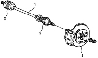
図1は、一般の車両の駆動軸を示す斜視図であり、一般に車両の駆動軸1には変速機側に連結する部分とディスク3に連結する部分の二個所に等速ジョイント2が設けられている。
従来、前記変速機側にはダブルオフセット型ジョイント(double offset joint)や三脚型ジョイント(tripod joint)が用いられ、ディスクに連結する側にはバーフィールド型ジョイント(birfield joint)が用いられている。
【0004】
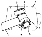
図2は、従来の三脚型ジョイントを示す斜視図であり、変速機側に連結されるハウジング4の内側面に、トラニオン5にベアリング6を介してローラ7が結合された組立体が三個所に等角度間隔で設けられ、組立体の間に駆動軸1が連結され、変速機側からの駆動力が同じ速度で伝えられるようにする。
即ち、等速ジョイントは、上記のような変速機側またはリアデファレンシャルサイドギアに設けられ、ハウジング4が回転すると、前記ローラ7が回転するようになり、結局、駆動軸1が共に回転するようになる。
【0005】
しかし、このような等速ジョイントは、駆動軸1に伝えられる軸力によって、車体の横方向への揺れが発生する恐れがある。
即ち、駆動軸1に伝えられる軸力は、図3に示すように、低段加速時にトルクが増加すると共に、車両の前部が持ち上がることによって、ジョイント折角が大きくなり、結局、この軸力(P=Ft*sinθ+f1:図4のP1、P2)が横揺れを引き起こすと言う問題点があった(図4参考)。
【0006】
上記図3のf2は、ローラ7とハウジング4の溝との間のトラニオン5方向の摩擦力を示し、f3は、ローラ7とトラニオン5との間の摩擦力を示す。
上記問題点を改善するためにこれを改良したシャダレスジョイント(shudderless joint)を用いることによって、軸力の相当部分の低減が可能であるが、これでは、上記問題点を根本的に解決することができなかった。即ち、このシャダレスジョイントもまた、ローラの摩擦力であるf3成分が駆動軸に直ちに伝えられる構造であるため、軸力を完全に低減できない問題点があった。
【先行技術文献】
【特許文献1】特開2002−080878
【特許文献2】特開2001−225605
【0007】
【発明が解決しようとする課題】
本発明は、上記問題点に鑑みてなされたものであり、ベアリング、ローラ、トラニオン間の摩擦力を低減させ、ローラのトラニオン摺動摩擦力が駆動軸でないハウジングに伝えられて変速機側で相殺されるようにし、横方向への揺れを有効に低減させ、シャダレスジョイントが必要なく、挿入部に設けられる溝の鍛造製作が可能であり、スプライン加工の必要のない等速ジョイントを提供することを目的とする。
【0008】
【課題を解決するための手段】
上記の目的を達成するため、本発明による等速ジョイントは、円筒殻状に形成されるハウジングと、該ハウジングの内側方向に等方向で三個所に設けられるトラニオンと、該トラニオンに結合され設置されるベアリングと、該ベアリングの外側に結合されるローラと、該球面ローラが設けられたハウジングの内側に結合されるように三個所に等間隔で溝が設けられた挿入部が端部に連結されている駆動軸とを備えることを特徴とする。
【0009】
【発明の実施の形態】
以下、本発明の好ましい実施の形態を、添付図面に基づいて詳しく説明する。
図5は、本発明による等速ジョイントの実施の形態を示す斜視図であり、図6は、本発明の等速ジョイントの実施の形態を示す側面図であり、図7は、図6のA−A線による断面図である。
【0010】
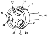
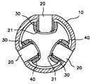
本発明は、円筒殻状に形成されるハウジング10と、該ハウジング10の内側方向に等方向で三個所に設けられるトラニオン20と、該トラニオン20に結合され設置されるベアリング30と、該ベアリング30の外側に結合されるローラ40と、前記ローラ40が設けられたハウジング10の内側に結合されるように三個所に等間隔で溝51が設けられた挿入部52が端部に連結された駆動軸50とを備えたことを技術上の特徴とする。
【0011】
ローラ40の転がり面と、溝51のローラ40の接触面とは、球面に形成され、ローラ40の転がりによる摩擦力を最小にすると共に軸方向への動きが発生しないようにする。
また、トラニオン20は、ハウジング10の周りに沿って等間隔に設けられた孔に挿入し、押込または接着剤によって固定させ、その周囲にベアリング30とローラ40を順に設置する。
ベアリング30は、図示のように、トラニオン20の周囲を取り囲む構造の円筒殻状をなすニードルベアリングを用いる。
さらに、トラニオン20には、ベアリング30が挿入部52の溝51に接触しないようにするスペーサ21が設けられてもよい。
【0012】
以下、上記図5乃至図7を参照して、本発明の作用及び効果を説明する。
本発明による等速ジョイントは、三脚型ジョイントにおいて、トラニオン20とベアリング30とローラ40とがハウジング10に取り付けられることがその特徴である。
このような構成によって、トラニオン20の摺動摩擦力が駆動軸50でなく、ハウジング10に伝えられ、変速機側で相殺される。
【0013】
即ち、ベアリング30とローラ40間の摩擦力、ローラ40とハウジング間のトラニオン20の軸に対する回転摩擦力、ローラ40とハウジング間のトラニオン20の軸に対する軸方向(線形)摩擦力が減少され、また、ローラ40のスピン力が低減するようになる。
従って、駆動軸50への軸力伝達量が小さくなり、横方向への揺れを根本的に低減することができる。
【0014】
また、このような本発明の等速ジョイントを適用する場合、上記のように軸力低減効果に優れているので、高価のシャダレスジョイントを使用することなく、シャダレスジョイントを本発明の等速ジョイントに連結して使用する場合は、軸力の低減効果がより大きくなる。
さらに、挿入部52に設けられる溝51は一般の鍛造加工で形成することができ、従来のスプライン加工を行う必要がない。
上記実施の形態は、本発明の技術的思想を具体的に説明するための一例であって、本発明の範囲は上記した図面または実施の形態に限定されるのではない。
【0015】
【発明の効果】
以上、本発明によると、ベアリング、ローラ、トラニオン間の摩擦力を低減させ、トラニオンに対するローラの摩擦力が駆動軸でなく、ハウジングに伝えられ、変速機側で相殺されるようにし、横方向への揺れを有効に低減させることができ、シャダレスジョイントを必要とせず、挿入部に設けられる溝の鍛造製作が可能であり、スプライン加工を行わなくてもよい効果がある。
【図面の簡単な説明】
【図1】一般の車両の駆動軸を示す斜視図である。
【図2】従来の三脚型ジョイントを示す斜視図である。
【図3】従来の三脚型ジョイント力の成分を示す概略図である。
【図4】従来の車両の駆動軸の作動状態を示す概略図である。
【図5】本発明による等速ジョイントの一実施の形態を示す斜視図である。
【図6】本発明による等速ジョイントの一実施の形態を示す側面図である。
【図7】図6のA−Aによる断面図である。
【符号の説明】
10 ハウジング
20 トラニオン
30 ベアリング
40 ローラ
50 駆動軸
51 溝
52 挿入部[0001]
TECHNICAL FIELD OF THE INVENTION
The present invention relates to a constant velocity joint, and in particular, in a tripod constant velocity joint provided on a drive shaft of a vehicle, by providing a trunnion, a bearing, and a roller in a housing, the trunnion sliding friction force of the roller is applied to a housing that is not a drive shaft. The present invention relates to a constant velocity joint capable of effectively reducing lateral sway by transmitting and canceling on the transmission side.
[0002]
[Prior art]
A constant velocity joint is a joint that can move smoothly and uniformly at a constant speed even when the crossing angle between the drive shaft and the passive shaft increases. Are combined.
[0003]
FIG. 1 is a perspective view showing a drive shaft of a general vehicle. In general, a
Conventionally, a double offset type joint or a tripod joint has been used on the transmission side, and a barfield type joint has been used on the side connected to the disk.
[0004]
FIG. 2 is a perspective view showing a conventional tripod type joint. At three places, an assembly in which a
That is, the constant velocity joint is provided on the transmission side or the rear differential side gear as described above, and when the
[0005]
However, such a constant velocity joint may cause the vehicle body to sway in the lateral direction due to the axial force transmitted to the
That is, as shown in FIG. 3, the axial force transmitted to the
[0006]
3 indicates the frictional force between the
By using a shudderless joint which is an improvement of the above problem, it is possible to reduce a considerable portion of the axial force, but this problem is to solve the above problem fundamentally. Could not. That is, this shaderless joint also has a problem that the axial force cannot be reduced completely because the f3 component, which is the frictional force of the roller, is immediately transmitted to the drive shaft.
[Prior art documents]
[Patent Document 1] JP-A-2002-080878
[Patent Document 2] JP-A-2001-225605
[0007]
[Problems to be solved by the invention]
The present invention has been made in view of the above problems, and reduces the frictional force between a bearing, a roller, and a trunnion. In order to provide a constant velocity joint which can effectively reduce lateral shaking, eliminates the need for a shadaless joint, allows forging production of grooves provided in the insertion part, and does not require spline processing. Aim.
[0008]
[Means for Solving the Problems]
In order to achieve the above object, a constant velocity joint according to the present invention is provided with a housing formed in a cylindrical shell shape, trunnions provided at three places in the housing in an equal direction in an inward direction, and connected and installed to the trunnion. Bearings, a roller coupled to the outside of the bearing, and an insertion portion provided with grooves at three locations at equal intervals so as to be coupled to the inside of the housing provided with the spherical roller. And a driving shaft.
[0009]
BEST MODE FOR CARRYING OUT THE INVENTION
Hereinafter, preferred embodiments of the present invention will be described in detail with reference to the accompanying drawings.
FIG. 5 is a perspective view showing an embodiment of the constant velocity joint according to the present invention, FIG. 6 is a side view showing an embodiment of the constant velocity joint of the present invention, and FIG. It is sectional drawing by the -A line.
[0010]
The present invention includes a
[0011]
The rolling surface of the
Further, the
As the
Further, the
[0012]
The operation and effect of the present invention will be described below with reference to FIGS.
The constant velocity joint according to the present invention is characterized in that a
With such a configuration, the sliding frictional force of the
[0013]
That is, the frictional force between the
Therefore, the amount of axial force transmitted to the
[0014]
Further, when such a constant velocity joint of the present invention is applied, since the axial force reducing effect is excellent as described above, the constant velocity joint of the present invention can be used without using an expensive shaderless joint. When used in connection with a joint, the effect of reducing the axial force is greater.
Further, the
The above embodiment is an example for specifically explaining the technical idea of the present invention, and the scope of the present invention is not limited to the above-described drawings and embodiments.
[0015]
【The invention's effect】
As described above, according to the present invention, the frictional force between the bearing, the roller, and the trunnion is reduced, so that the frictional force of the roller with respect to the trunnion is transmitted to the housing, not to the drive shaft, and is offset on the transmission side. The shaking of the groove provided in the insertion portion can be forged without the need for a shudderless joint, and the spline processing can be omitted.
[Brief description of the drawings]
FIG. 1 is a perspective view showing a drive shaft of a general vehicle.
FIG. 2 is a perspective view showing a conventional tripod joint.
FIG. 3 is a schematic diagram showing components of a conventional tripod joint force.
FIG. 4 is a schematic view showing an operation state of a drive shaft of a conventional vehicle.
FIG. 5 is a perspective view showing one embodiment of a constant velocity joint according to the present invention.
FIG. 6 is a side view showing one embodiment of a constant velocity joint according to the present invention.
FIG. 7 is a sectional view along AA in FIG. 6;
[Explanation of symbols]
Claims (4)
前記ハウジングの内側方向に等方向で三個所に設けられるトラニオンと、
前記トラニオンに結合され設置されるベアリングと、
前記ベアリングの外側に結合されるローラと、
前記ローラが設けられたハウジングの内側に結合されるように三個所に等間隔で溝が設けられた挿入部が端部に連結されている駆動軸と、
を備えることを特徴とする等速ジョイント。A housing formed in a cylindrical shell shape;
Trunnions provided at three places in the same direction in the interior direction of the housing,
A bearing coupled to and installed on the trunnion;
A roller coupled to the outside of the bearing;
A drive shaft connected to an end having an insertion portion provided with grooves at three locations at equal intervals so as to be coupled to the inside of the housing provided with the rollers,
A constant velocity joint comprising:
Applications Claiming Priority (1)
| Application Number | Priority Date | Filing Date | Title |
|---|---|---|---|
| KR10-2002-0031377A KR100461259B1 (en) | 2002-06-04 | 2002-06-04 | Constant velocity joints |
Publications (1)
| Publication Number | Publication Date |
|---|---|
| JP2004011907A true JP2004011907A (en) | 2004-01-15 |
Family
ID=29546394
Family Applications (1)
| Application Number | Title | Priority Date | Filing Date |
|---|---|---|---|
| JP2002347409A Pending JP2004011907A (en) | 2002-06-04 | 2002-11-29 | Constant velocity joint |
Country Status (4)
| Country | Link |
|---|---|
| US (1) | US20030224860A1 (en) |
| EP (1) | EP1369609A3 (en) |
| JP (1) | JP2004011907A (en) |
| KR (1) | KR100461259B1 (en) |
Cited By (1)
| Publication number | Priority date | Publication date | Assignee | Title |
|---|---|---|---|---|
| JP7114129B1 (en) * | 2021-12-07 | 2022-08-08 | 株式会社クロイツ | Universal joint mechanism, tool joint and tool drive unit |
Families Citing this family (3)
| Publication number | Priority date | Publication date | Assignee | Title |
|---|---|---|---|---|
| US7097565B2 (en) * | 2004-08-09 | 2006-08-29 | Torque-Traction Technologies, Llc | Fixed-center articulating constant velocity joint |
| CN104061249A (en) * | 2014-06-27 | 2014-09-24 | 苏州市海神达机械科技有限公司 | Universal extensible joint |
| JP6719912B2 (en) * | 2016-01-21 | 2020-07-08 | 昌弘 町田 | Rotation transmission mechanism |
Family Cites Families (12)
| Publication number | Priority date | Publication date | Assignee | Title |
|---|---|---|---|---|
| FR1250605A (en) * | 1959-12-02 | 1961-01-13 | Transmission seal | |
| US3877251A (en) * | 1973-06-15 | 1975-04-15 | Wahlmark Systems | Universal joint system |
| JPS5941048B2 (en) * | 1975-04-23 | 1984-10-04 | ユニ − カルダン アクチエンゲゼルシヤフト | synchronous rotary joint |
| JPS5445442A (en) * | 1977-09-19 | 1979-04-10 | Honda Motor Co Ltd | Sliding type equal-speed universal joint |
| JPS5467841A (en) * | 1977-11-09 | 1979-05-31 | Toyota Motor Corp | Outer part of equal-speed universal joint and its manufacturing process |
| DE3041855C2 (en) * | 1980-11-06 | 1984-07-05 | Löhr & Bromkamp GmbH, 6050 Offenbach | Storage arrangement |
| FR2506872B1 (en) * | 1981-06-01 | 1986-05-09 | Glaenzer Spicer Sa | TELESCOPIC HOMOCINETIC JOINT |
| FR2548595B1 (en) * | 1983-07-04 | 1988-05-27 | Glaenzer Spicer Sa | VEHICLE DRIVE WHEEL HUB ASSEMBLY |
| FR2699620B1 (en) * | 1992-12-17 | 1995-03-17 | Gkn Glaenzer Spicer | Articulated joint with rollers. |
| JP3692663B2 (en) * | 1996-10-31 | 2005-09-07 | 日本精工株式会社 | Tripod type constant velocity joint |
| JP3982863B2 (en) * | 1997-01-27 | 2007-09-26 | 日本精工株式会社 | Tripod type constant velocity joint |
| JP4178613B2 (en) * | 1998-09-02 | 2008-11-12 | 日本精工株式会社 | Tripod type constant velocity joint |
-
2002
- 2002-06-04 KR KR10-2002-0031377A patent/KR100461259B1/en not_active IP Right Cessation
- 2002-11-25 EP EP02026192A patent/EP1369609A3/en not_active Withdrawn
- 2002-11-26 US US10/306,652 patent/US20030224860A1/en not_active Abandoned
- 2002-11-29 JP JP2002347409A patent/JP2004011907A/en active Pending
Cited By (1)
| Publication number | Priority date | Publication date | Assignee | Title |
|---|---|---|---|---|
| JP7114129B1 (en) * | 2021-12-07 | 2022-08-08 | 株式会社クロイツ | Universal joint mechanism, tool joint and tool drive unit |
Also Published As
| Publication number | Publication date |
|---|---|
| KR20030094557A (en) | 2003-12-18 |
| EP1369609A2 (en) | 2003-12-10 |
| US20030224860A1 (en) | 2003-12-04 |
| EP1369609A3 (en) | 2004-09-01 |
| KR100461259B1 (en) | 2004-12-10 |
Similar Documents
| Publication | Publication Date | Title |
|---|---|---|
| EP2594821B1 (en) | Ball type constant velocity joint for vehicle | |
| JPH1191307A (en) | Hub unit | |
| JP2004011907A (en) | Constant velocity joint | |
| JP2000170755A (en) | Shell type needle-shaped roller bearing for universal joint | |
| JP2007198399A (en) | Power transmission shaft | |
| JP2007309340A (en) | Cross shaft coupling and vehicular steering device using the same | |
| JP2006258255A (en) | Tripod type constant velocity universal coupling | |
| KR101648668B1 (en) | Constant velocity joint apparatus | |
| JP2006266324A (en) | Constant velocity universal joint | |
| JP2006283831A (en) | Constant velocity universal joint | |
| KR20100057332A (en) | Spider and shaft assembly for constant velocity joint | |
| JP2006266325A (en) | Constant velocity universal joint | |
| KR20060060342A (en) | Tripod constant velocity joint | |
| KR100706081B1 (en) | Structure for tripod constant velocity joint | |
| JP4178613B2 (en) | Tripod type constant velocity joint | |
| JP2008019952A (en) | Tripod type constant velocity universal joint | |
| JP2001311432A (en) | Constant velocity universal joint | |
| KR100476712B1 (en) | Anti axial force tripod constant velocity joint | |
| KR100834214B1 (en) | tripod type constant velocity joint | |
| JP2006266327A (en) | Constant velocity universal joint | |
| KR20110035108A (en) | Outboard constant velocity joint for vehicle | |
| JP2006266323A (en) | Constant velocity universal joint | |
| JP2010127312A (en) | Fixed type constant velocity universal joint and wheel drive device using the same | |
| JP2005226776A (en) | Tripod type constant velocity universal joint | |
| JP2007182973A (en) | Constant velocity universal joint and its manufacturing method |
Legal Events
| Date | Code | Title | Description |
|---|---|---|---|
| A977 | Report on retrieval |
Free format text: JAPANESE INTERMEDIATE CODE: A971007 Effective date: 20041020 |
|
| A131 | Notification of reasons for refusal |
Free format text: JAPANESE INTERMEDIATE CODE: A131 Effective date: 20041102 |
|
| A02 | Decision of refusal |
Free format text: JAPANESE INTERMEDIATE CODE: A02 Effective date: 20050412 |