ES2883149T3 - Apparatus for removing liquid and method of removing liquid - Google Patents
Apparatus for removing liquid and method of removing liquid Download PDFInfo
- Publication number
- ES2883149T3 ES2883149T3 ES17775248T ES17775248T ES2883149T3 ES 2883149 T3 ES2883149 T3 ES 2883149T3 ES 17775248 T ES17775248 T ES 17775248T ES 17775248 T ES17775248 T ES 17775248T ES 2883149 T3 ES2883149 T3 ES 2883149T3
- Authority
- ES
- Spain
- Prior art keywords
- steel sheet
- gap
- nozzle
- slot nozzle
- slot
- Prior art date
- Legal status (The legal status is an assumption and is not a legal conclusion. Google has not performed a legal analysis and makes no representation as to the accuracy of the status listed.)
- Active
Links
Classifications
-
- C—CHEMISTRY; METALLURGY
- C23—COATING METALLIC MATERIAL; COATING MATERIAL WITH METALLIC MATERIAL; CHEMICAL SURFACE TREATMENT; DIFFUSION TREATMENT OF METALLIC MATERIAL; COATING BY VACUUM EVAPORATION, BY SPUTTERING, BY ION IMPLANTATION OR BY CHEMICAL VAPOUR DEPOSITION, IN GENERAL; INHIBITING CORROSION OF METALLIC MATERIAL OR INCRUSTATION IN GENERAL
- C23G—CLEANING OR DE-GREASING OF METALLIC MATERIAL BY CHEMICAL METHODS OTHER THAN ELECTROLYSIS
- C23G3/00—Apparatus for cleaning or pickling metallic material
- C23G3/02—Apparatus for cleaning or pickling metallic material for cleaning wires, strips, filaments continuously
- C23G3/027—Associated apparatus, e.g. for pretreating or after-treating
- C23G3/029—Associated apparatus, e.g. for pretreating or after-treating for removing the pickling fluid from the objects
-
- C—CHEMISTRY; METALLURGY
- C23—COATING METALLIC MATERIAL; COATING MATERIAL WITH METALLIC MATERIAL; CHEMICAL SURFACE TREATMENT; DIFFUSION TREATMENT OF METALLIC MATERIAL; COATING BY VACUUM EVAPORATION, BY SPUTTERING, BY ION IMPLANTATION OR BY CHEMICAL VAPOUR DEPOSITION, IN GENERAL; INHIBITING CORROSION OF METALLIC MATERIAL OR INCRUSTATION IN GENERAL
- C23G—CLEANING OR DE-GREASING OF METALLIC MATERIAL BY CHEMICAL METHODS OTHER THAN ELECTROLYSIS
- C23G1/00—Cleaning or pickling metallic material with solutions or molten salts
- C23G1/02—Cleaning or pickling metallic material with solutions or molten salts with acid solutions
- C23G1/08—Iron or steel
-
- C—CHEMISTRY; METALLURGY
- C23—COATING METALLIC MATERIAL; COATING MATERIAL WITH METALLIC MATERIAL; CHEMICAL SURFACE TREATMENT; DIFFUSION TREATMENT OF METALLIC MATERIAL; COATING BY VACUUM EVAPORATION, BY SPUTTERING, BY ION IMPLANTATION OR BY CHEMICAL VAPOUR DEPOSITION, IN GENERAL; INHIBITING CORROSION OF METALLIC MATERIAL OR INCRUSTATION IN GENERAL
- C23G—CLEANING OR DE-GREASING OF METALLIC MATERIAL BY CHEMICAL METHODS OTHER THAN ELECTROLYSIS
- C23G3/00—Apparatus for cleaning or pickling metallic material
- C23G3/02—Apparatus for cleaning or pickling metallic material for cleaning wires, strips, filaments continuously
- C23G3/023—Apparatus for cleaning or pickling metallic material for cleaning wires, strips, filaments continuously by spraying
-
- C—CHEMISTRY; METALLURGY
- C23—COATING METALLIC MATERIAL; COATING MATERIAL WITH METALLIC MATERIAL; CHEMICAL SURFACE TREATMENT; DIFFUSION TREATMENT OF METALLIC MATERIAL; COATING BY VACUUM EVAPORATION, BY SPUTTERING, BY ION IMPLANTATION OR BY CHEMICAL VAPOUR DEPOSITION, IN GENERAL; INHIBITING CORROSION OF METALLIC MATERIAL OR INCRUSTATION IN GENERAL
- C23G—CLEANING OR DE-GREASING OF METALLIC MATERIAL BY CHEMICAL METHODS OTHER THAN ELECTROLYSIS
- C23G3/00—Apparatus for cleaning or pickling metallic material
- C23G3/02—Apparatus for cleaning or pickling metallic material for cleaning wires, strips, filaments continuously
- C23G3/025—Details of the apparatus, e.g. linings or sealing means
- C23G3/026—Details of the apparatus, e.g. linings or sealing means for guiding the objects
-
- B—PERFORMING OPERATIONS; TRANSPORTING
- B21—MECHANICAL METAL-WORKING WITHOUT ESSENTIALLY REMOVING MATERIAL; PUNCHING METAL
- B21B—ROLLING OF METAL
- B21B45/00—Devices for surface or other treatment of work, specially combined with or arranged in, or specially adapted for use in connection with, metal-rolling mills
- B21B45/02—Devices for surface or other treatment of work, specially combined with or arranged in, or specially adapted for use in connection with, metal-rolling mills for lubricating, cooling, or cleaning
- B21B45/0269—Cleaning
- B21B45/0275—Cleaning devices
- B21B45/0278—Cleaning devices removing liquids
Landscapes
- Chemical & Material Sciences (AREA)
- Chemical Kinetics & Catalysis (AREA)
- General Chemical & Material Sciences (AREA)
- Engineering & Computer Science (AREA)
- Materials Engineering (AREA)
- Mechanical Engineering (AREA)
- Metallurgy (AREA)
- Organic Chemistry (AREA)
- Cleaning In General (AREA)
- Cleaning And De-Greasing Of Metallic Materials By Chemical Methods (AREA)
- Cleaning By Liquid Or Steam (AREA)
- Nozzles (AREA)
Abstract
Un método para retirar líquido que retira líquido adherido a una superficie de una lámina (S) de acero que ha sido sometida a un paso de decapado para retirar la costra de oxidación, en donde el método para retirar líquido comprende: utilizar un dispositivo (1) de retirada de líquido, que comprende una boquilla (10) de ranura que eyecta gas desde un puerto (112; 216) de eyección hacia la superficie de una lámina (S) de acero; un dispositivo (30) de medida de hueco que mide un hueco existente entre el puerto (112; 216) de eyección de la boquilla (10) de ranura y la lámina (S) de acero; y un mecanismo (40) de ajuste de hueco que ajusta el hueco sobre la base del resultado de una medida llevada a cabo por el dispositivo (30) de medida de hueco, en donde la boquilla (10) de ranura está instalada de manera que eyecta gas desde un lado aguas abajo hacia un lado aguas arriba en una dirección de movimiento de la lámina (S) de acero que se mueve en relación a la boquilla de ranura; la dirección de movimiento de la lámina (S) de acero es una dirección horizontal; y la boquilla (10) de ranura satisface las siguientes ecuaciones relacionales: [Mat 1] **(Ver fórmula)** en donde la presión de gas en el interior de la boquilla (10) de ranura se define como presión Pn [KPa] de boquilla; un ángulo formado por una dirección perpendicular a la superficie de la lámina (S) de acero y una dirección de eyección del gas se define como un ángulo θ [º] de eyección; un ángulo formado por la dirección de eyección del gas y una cara (104) posterior de boquilla que es una cara dispuesta desde el puerto (112; 216) de eyección de la boquilla (10) de ranura hacia el lado aguas abajo en la dirección de movimiento se define como un ángulo β [º] de inclinación de cara posterior; una longitud de la cara (104) posterior de boquilla en la dirección de movimiento se define como L [mm]; el hueco se define como h [mm]; y un grosor de ranura de la boquilla (10) de ranura se define como d [mm], en donde el método para retirar líquido comprende adicionalmente un paso de medir, en el que el dispositivo (30) de medida de hueco mide un hueco existente entre el puerto (112; 216) de eyección de la boquilla (10) de ranura y la lámina (S) de acero; un paso de ajustar hueco, en el que se ajusta el hueco a un valor menor o igual a 20 mm cambiando una posición de al menos un elemento de entre la boquilla (10) de ranura y lámina (S) de acero sobre la base del hueco medido; y un paso de retirar líquido, en el que se retira el líquido adherido a la superficie de la lámina (S) de acero mediante la eyección de gas desde la boquilla (10) de ranura hacia la superficie de la lámina (S) de acero mientras se produce un movimiento relativo entre la boquilla (10) de ranura y lámina (S) de acero.A method for removing liquid that removes liquid adhering to a surface of a steel sheet (S) that has been subjected to a pickling step to remove oxidation scale, wherein the method for removing liquid comprises: using a device (1 ) for removing liquid, comprising a slot nozzle (10) that ejects gas from an ejection port (112; 216) towards the surface of a steel sheet (S); a gap measuring device (30) that measures a gap between the ejection port (112; 216) of the slot nozzle (10) and the steel sheet (S); and a gap adjusting mechanism (40) that adjusts the gap based on the result of a measurement carried out by the gap measuring device (30), wherein the slot nozzle (10) is installed so as to ejects gas from a downstream side to an upstream side in a moving direction of the steel sheet (S) moving relative to the slot nozzle; the direction of movement of the steel sheet (S) is a horizontal direction; and the slot nozzle (10) satisfies the following relational equations: [Mat 1] **(See formula)** where the gas pressure inside the slot nozzle (10) is defined as pressure Pn [KPa ] mouthpiece; an angle formed by a direction perpendicular to the surface of the steel sheet (S) and a gas ejection direction is defined as an ejection angle θ[°]; an angle formed by the gas ejection direction and a nozzle rear face (104) which is a face disposed from the ejection port (112; 216) of the slot nozzle (10) toward the downstream side in the direction of movement is defined as an angle β [º] of inclination of the rear face; a length of the nozzle rear face (104) in the moving direction is defined as L [mm]; the gap is defined as h [mm]; and a slot thickness of the slot nozzle (10) is defined as d [mm], wherein the method for removing liquid further comprises a measuring step, wherein the gap measuring device (30) measures a gap. existing between the slot nozzle (10) ejection port (112; 216) and the steel sheet (S); an adjust gap step, in which the gap is adjusted to a value less than or equal to 20 mm by changing a position of at least one element between the slot nozzle (10) and steel sheet (S) on the basis of the measured gap; and a step of removing liquid, in which liquid adhering to the surface of the steel sheet (S) is removed by ejecting gas from the slot nozzle (10) towards the surface of the steel sheet (S). while a relative movement is produced between the slot nozzle (10) and the steel sheet (S).
Description
DESCRIPCIÓNDESCRIPTION
Aparato para retirar líquido y método para retirar líquidoApparatus for withdrawing liquid and method for withdrawing liquid
Campo técnicotechnical field
La presente invención se refiere a un método para retirar líquido que retira el líquido adherido a la superficie de un elemento de tipo lámina.The present invention relates to a liquid removal method that removes liquid adhering to the surface of a sheet-like member.
Antecedentes de la técnicaBackground art
En la superficie de una lámina de acero después de un proceso de laminado en caliente se forma una película de óxido llamada costra de oxidación. Puesto que la costra de oxidación produce un defecto o un tipo de imperfección en la lámina de acero, resulta necesario llevar a cabo un decapado de la lámina de acero con ácido clorhídrico, ácido sulfúrico o un ácido de ese tipo. En una línea de decapado continuo convencional, una lámina de acero en forma de bobina es desenrollada mediante una desenrolladora y sometida a nivelación mediante una niveladora, el extremo trasero de una lámina de acero precedente y el extremo delantero de una lámina de acero siguiente se sueldan para proporcionar una lámina de acero continua, y acto seguido la lámina de acero se hace pasar a través de un baño de decapado para retirar la costra de oxidación de su superficie utilizando una disolución. El ácido o el agua adheridos a la superficie de la lámina de acero de la que se ha retirado la costra de oxidación en el baño de decapado se retiran en un baño de lavado, la lámina de acero se seca entonces en una secadora, y a continuación se enrolla para adoptar de nuevo una forma bobinada.An oxide film called rust scale forms on the surface of a steel sheet after a hot rolling process. Since the oxidation scale causes a defect or a kind of imperfection in the steel sheet, it is necessary to carry out pickling of the steel sheet with hydrochloric acid, sulfuric acid or such an acid. In a conventional continuous pickling line, a coil-shaped steel sheet is uncoiled by an uncoiler and leveled by a leveler, the trailing end of a preceding steel sheet and the leading end of a following steel sheet are welded. to provide a continuous steel sheet, and the steel sheet is then passed through a pickling bath to remove oxidation scale on its surface using a solution. Acid or water adhering to the surface of the steel sheet from which the oxidation scale has been removed in the pickling bath is removed in a washing bath, the steel sheet is then dried in a dryer, and then it is rolled up to assume a coiled shape again.
Convencionalmente, con el fin de retirar ácido, agua o líquidos de ese tipo adheridos a una lámina de acero, se ha utilizado una pareja de rodillos escurridores que están instalados en un baño de lavado y que retiran líquido en la lámina de acero que pasa a su través, y una secadora que sopla, mediante aire caliente, el líquido que permanece en la superficie de la lámina de acero que ha pasado a través de los rodillos escurridores para conseguir el secado. El rodillo escurridor, cuya superficie está hecha de una capa de caucho liso, estruja el líquido adherido a la superficie de la lámina de acero al ser presionado contra la lámina de acero.Conventionally, in order to remove acid, water or liquids of that type adhering to a steel sheet, a pair of squeegee rollers have been used that are installed in a washing bath and that remove liquid in the steel sheet that passes to through it, and a dryer that blows, by means of hot air, the liquid that remains on the surface of the steel sheet that has passed through the draining rollers to achieve drying. The squeegee roller, whose surface is made of smooth rubber layer, squeezes the liquid attached to the surface of the steel sheet by being pressed against the steel sheet.
En ese momento, si existe un hueco entre los rodillos escurridores y ambos extremos de la lámina de acero, se acumula líquido en el hueco y el líquido permanece en forma de franja en superficies de ambos extremos de la lámina de acero que han pasado a través de los rodillos escurridores. Además, si los rodillos escurridores se utilizan durante un periodo de tiempo largo, se desgastan porciones correspondientes a ambos extremos de la lámina de acero provocando la aparición de un espacio en el que los rodillos escurridores no entran en contacto con la lámina de acero, lo que aumenta el intervalo en el que el líquido permanece sobre la superficie de la lámina de acero. Si como consecuencia de ello permanece algo de líquido en la superficie de la lámina de acero que ha pasado a través de los rodillos escurridores, el líquido no podrá ser soplado en la medida suficiente por parte de la secadora.At that time, if there is a gap between the squeegee rollers and both ends of the steel sheet, liquid accumulates in the gap, and the liquid remains in the form of a streak on surfaces of both ends of the steel sheet that have passed through. of the squeegee rollers. In addition, if the squeegee rollers are used for a long period of time, portions corresponding to both ends of the steel sheet are worn, causing a gap to appear where the squeegee rollers do not contact the steel sheet, which which increases the interval in which the liquid remains on the surface of the steel sheet. If as a consequence some liquid remains on the surface of the steel sheet which has passed through the squeegee rollers, the liquid cannot be sufficiently blown by the dryer.
Por todo ello, se ha propuesto una tecnología para instalar dispositivos de drenaje de líquido entre los rodillos escurridores y la secadora y la retirada de líquido que permanece después de que la lámina pase a través de los rodillos escurridores. Por ejemplo, la referencia 1 de la Biografía de Patentes describe un método de retirada de líquido que incluye una pareja de rodillos de drenaje de líquido que retiran, mediante una prensa, el líquido adherido a las superficies superior e inferior de una tira de acero, y una boquilla que eyecta un chorro de gas a un hueco formado entre los rodillos de drenaje de líquido y un extremo de la tira de acero, con una determinada velocidad de flujo, desde el centro de la tira de acero hacia el extremo de la tira de acero. Las referencias 2 y 3 de la Biografía de Patentes describen métodos adicionales para retirar líquidos de decapado de una lámina de acero.Therefore, a technology for installing liquid drainage devices between the squeegee rollers and the dryer and removing liquid remaining after the sheet passes through the squeegee rollers has been proposed. For example, reference 1 of the Patent Biography describes a liquid removal method that includes a pair of liquid drainage rollers that remove, by means of a press, the liquid adhering to the upper and lower surfaces of a steel strip, and a nozzle that ejects a jet of gas into a gap formed between the liquid drain rollers and an end of the steel strip, with a certain flow rate, from the center of the steel strip toward the end of the strip. of steel. References 2 and 3 of the Patent Biography describe additional methods for removing pickling liquids from steel sheet.
Lista de Referencias BibliográficasList of Bibliographical References
Bibliografía de PatentesPatent Bibliography
Biografía de Patentes 1: JP H6-65766APatent Biography 1: JP H6-65766A
Biografía de Patentes 2: JP 2008-023561 APatent Biography 2: JP 2008-023561 A
Biografía de Patentes 3: JP 2002-294478 APatent Biography 3: JP 2002-294478 A
Sumario de la InvenciónSummary of the Invention
Problema técnicotechnical problem
Sin embargo, existe un problema en cuanto a que, incluso si se utiliza el método de retirada de líquido descrito en la referencia 1 de la Biografía de Patentes, resulta necesario proporcionar tanto los rodillos escurridores como la secadora, lo que aumenta el coste de mantenimiento del equipo.However, there is a problem that even if the liquid removal method described in reference 1 of the Patent Biography is used, it is necessary to provide both the squeegee rollers and the dryer, which increases the maintenance cost. of the team.
Por lo tanto, en vista del problema mencionado, un propósito de la presente invención es proporcionar un dispositivo novedoso y mejorado de retirada de líquido y un método de retirada de líquido que utilice éste, que sean capaces de retirar líquido en una lámina de acero sin utilizar ni rodillos escurridores ni una secadora. Therefore, in view of the above problem, it is an object of the present invention to provide a novel and improved liquid removal device and a liquid removal method using it, which are capable of removing liquid in a steel sheet without use neither squeegee rollers nor a dryer.
Solución al problemaSolution to the problem
De acuerdo con un aspecto de la presente invención, con el fin de conseguir el propósito antes mencionado, se proporciona un dispositivo de retirada de líquido que retira líquido adherido a una superficie de un elemento de tipo lámina que es transportado, en donde el dispositivo de retirada de líquido incluye: una boquilla de ranura que eyecta un chorro de gas hacia la superficie del elemento de tipo lámina; y un dispositivo de medida de hueco que mide un hueco entre un puerto de eyección de la boquilla de ranura y el elemento de tipo lámina. La boquilla de ranura está instalada de tal manera que eyecta un chorro de gas desde un lado aguas abajo hacia un lado aguas arriba en una dirección de movimiento del elemento de tipo lámina que se desplaza en relación a la boquilla de ranura. La boquilla de ranura cumple las siguientes ecuaciones relacionales:According to one aspect of the present invention, in order to achieve the aforementioned purpose, there is provided a liquid removal device that removes liquid adhered to a surface of a sheet-like item being conveyed, wherein the liquid removal device liquid withdrawal includes: a slot nozzle that ejects a jet of gas towards the surface of the sheet-like element; and a gap measuring device that measures a gap between an ejection port of the slot die and the sheet-like member. The slot nozzle is installed such that it ejects a jet of gas from a downstream side to an upstream side in a moving direction of the sheet-like member moving relative to the slot nozzle. The slot nozzle satisfies the following relational equations:
[Mat 1][Matt 1]

en donde Pn [KPa] representa la presión de boquilla, definida como la presión del gas en el interior de la boquilla de ranura; 0 [°] representa el ángulo de eyección, definido como un ángulo formado por una dirección perpendicular a la superficie del elemento de tipo lámina y una dirección de eyección del gas; b [°] representa el ángulo de inclinación de cara posterior, definido como un ángulo formado por la dirección de eyección del gas y una cara posterior de la boquilla que constituye una cara que se sitúa desde el puerto de eyección de la boquilla de ranura hacia el lado aguas abajo en la dirección de movimiento; L [mm] representa una longitud de la cara posterior de la boquilla en la dirección de movimiento; h [mm] representa el hueco; y d [mm] representa un grosor de la ranura de la boquilla de ranura.where Pn [KPa] represents the nozzle pressure, defined as the gas pressure inside the slot nozzle; 0 [°] represents the ejection angle, defined as an angle formed by a direction perpendicular to the surface of the sheet-like element and a gas ejection direction; b [°] represents the back face inclination angle, defined as an angle formed by the gas ejection direction and a nozzle back face that constitutes a face that is located from the slot nozzle ejection port towards the downstream side in the direction of movement; L [mm] represents a length of the rear face of the nozzle in the direction of movement; h [mm] represents the gap; and d [mm] represents a thickness of the groove of the groove nozzle.
El dispositivo de retirada de líquido puede incluir adicionalmente un mecanismo de ajuste de hueco que ajusta el hueco sobre la base del resultado de una medida llevada a cabo por el dispositivo de medida de hueco. El mecanismo de ajuste de hueco ajusta el hueco a un valor menor o igual a 20 mm.The liquid removal device may further include a gap adjustment mechanism that adjusts the gap based on the result of a measurement performed by the gap measurement device. The gap adjustment mechanism adjusts the gap to a value less than or equal to 20 mm.
El mecanismo de ajuste de hueco puede ajustar el hueco cambiando una posición de la boquilla de ranura.The gap adjustment mechanism can adjust the gap by changing a position of the slot nozzle.
De manera alternativa, cuando la lámina se desplaza en la dirección de movimiento por medio de una mesa de rodillos que transporta el elemento de tipo lámina, el mecanismo de ajuste de hueco ajusta el hueco cambiando la posición de la mesa de rodillos en la que está situado el elemento de tipo lámina.Alternatively, when the sheet is moved in the direction of movement by means of a roller table that conveys the sheet-like element, the gap adjustment mechanism adjusts the gap by changing the position of the roller table it is on. located the sheet-type element.
El dispositivo de medida de hueco puede medir el hueco en cada una de las posiciones de medida cerca de ambos extremos del puerto de eyección de la boquilla de ranura en una dirección longitudinal. El mecanismo de ajuste de hueco puede ajustar el hueco en cada una de las posiciones de medida a un valor menor o igual a 20 mm.The gap measuring device can measure the gap at each of the measuring positions near both ends of the slot nozzle ejection port in a longitudinal direction. The gap adjustment mechanism can adjust the gap at each measuring position to a value less than or equal to 20mm.
El dispositivo de medida de hueco puede medir el hueco mediante un telémetro láser, por ejemplo.The gap measurement device can measure the gap by means of a laser rangefinder, for example.
La boquilla de ranura puede estar fijada y la lámina puede desplazarse en relación a la boquilla de ranura al ser desplazada en la dirección de movimiento por el dispositivo transportador.The slot nozzle can be fixed and the sheet can move relative to the slot nozzle as it is moved in the direction of movement by the conveyor device.
El dispositivo transportador puede ser una mesa de rodillos sobre la que se sitúa la lámina.The conveyor device can be a roller table on which the sheet is placed.
De manera alternativa, el dispositivo transportador puede ser un dispositivo de enrollado/desenrollado que incluye un carrete de descarga que desenrolla el elemento de tipo lámina arrollado en forma de bobina, y un carrete de tensión que enrolla, dotando de forma de bobina, el elemento de tipo lámina del que se ha retirado el líquido.Alternatively, the conveyor device may be a winding/unwinding device including a discharge reel that unwinds the wound sheet-like element into a coil, and a take-up reel that winds into a coil form the element. sheet-type from which the liquid has been removed.
Adicionalmente, la lámina puede estar estacionaria, y la boquilla de ranura puede moverse en relación al elemento de tipo lámina por medio de un mecanismo de movimiento de boquilla.Additionally, the blade may be stationary, and the slot nozzle may be moved relative to the blade-like element by means of a nozzle moving mechanism.
La boquilla de ranura del dispositivo de retirada de líquido puede incluir un cuerpo principal de boquilla que incluye un puerto de eyección, y un canal de flujo de gas que guía, hasta el puerto de eyección, el gas que se suministra externamente, y un elemento de cara posterior que posee una cara posterior de la boquilla dispuesta para extenderse desde el puerto de eyección del cuerpo principal de boquilla hacia el lado aguas abajo en la dirección de movimiento de la lámina. En este momento, la cara posterior de la boquilla puede ser una contracara del elemento de cara posterior que mira hacia la superficie de la lámina.The slot nozzle of the liquid withdrawal device may include a nozzle main body including an ejection port, and a gas flow channel that guides externally supplied gas to the ejection port, and an element rear face having a nozzle rear face arranged to extend from the ejection port of the nozzle main body to the downstream side in the direction of sheet movement. At this time, the rear face of the nozzle may be a counter face of the rear face member facing the sheet surface.
Efectos ventajosos de la InvenciónAdvantageous Effects of the Invention
Tal como se ha descrito más arriba, de acuerdo con la presente invención, puede retirarse líquido de una lámina de acero sin utilizar ni rodillos escurridores ni una secadora. As described above, according to the present invention, liquid can be removed from a steel sheet without using either squeegee rolls or a dryer.
Breve descripción de los dibujosBrief description of the drawings
La FIGURA 1 es un diagrama explicativo que ilustra una situación de drenaje de líquido por parte de un dispositivo de retirada de líquido utilizando una boquilla de ranura común.FIGURE 1 is an explanatory diagram illustrating a situation of liquid drainage by a liquid removal device using a common slot nozzle.
La FIGURA 2 es un diagrama explicativo que ilustra una situación de drenaje de líquido por parte de un dispositivo de retirada de líquido utilizando una boquilla de ranura de acuerdo con una realización de la presente invención.FIGURE 2 is an explanatory diagram illustrating a situation of liquid drainage by a liquid removal device using a slot nozzle according to an embodiment of the present invention.
La FIGURA 3 es una vista lateral de un ejemplo de configuración de un dispositivo de retirada de líquido de acuerdo con la realización.FIGURE 3 is a side view of a configuration example of a liquid removal device according to the embodiment.
La FIGURA 4 es una vista trasera del dispositivo de retirada de líquido ilustrado en la FIGURA 3.FIGURE 4 is a rear view of the liquid withdrawal device illustrated in FIGURE 3.
La FIGURA 5 es un diagrama explicativo que ilustra una configuración detallada de una boquilla de ranura de acuerdo con la realización.FIGURE 5 is an explanatory diagram illustrating a detailed configuration of a slot nozzle according to the embodiment.
La FIGURA 6 es un diagrama explicativo que muestra un ejemplo de la relación entre una velocidad u+(x) de flujo y una velocidad u-(x) de flujo cuando una longitud L de cara posterior tiene un valor de 20 mm y la suma de un ángulo 0 de eyección y un ángulo b de inclinación de cara posterior tiene un valor de 90°.FIGURE 6 is an explanatory diagram showing an example of the relationship between a flow rate u+(x) and a flow rate u-(x) when a back face length L has a value of 20 mm and the sum of an ejection angle 0 and a back face tilt angle b has a value of 90°.
La FIGURA 7 es un diagrama explicativo que muestra un ejemplo de la relación entre la velocidad u+(x) de flujo y la velocidad u-(x) de flujo cuando la longitud L de cara posterior tiene un valor de 15 mm y la suma de un ángulo 0 de eyección y un ángulo b de inclinación de cara posterior tiene un valor de 50°.FIGURE 7 is an explanatory diagram showing an example of the relationship between the flow rate u+(x) and the flow rate u-(x) when the back face length L has a value of 15 mm and the sum of an ejection angle 0 and a back face tilt angle b have a value of 50°.
La FIGURA 8 es un diagrama explicativo que muestra la relación entre un hueco h y una presión Pn de boquilla cuando el ángulo 0 de eyección tiene un valor de 45° y se cambian los valores del ángulo b de inclinación de cara posterior y la longitud L de cara posterior.FIGURE 8 is an explanatory diagram showing the relationship between a gap h and a nozzle pressure Pn when the ejection angle 0 has a value of 45° and the values of the back face tilt angle b and the length L of the nozzle are changed. upper side.
La FIGURA 9 es un diagrama explicativo para describir un estado de flujo en una cara posterior de boquilla, en relación a las curvas de la gráfica de la FIGURA 8.FIGURE 9 is an explanatory diagram to describe a flow state in a rear face of the nozzle, in relation to the curves of the graph of FIGURE 8.
La FIGURA 10 es un diagrama explicativo que ilustra un ejemplo de modificación de una configuración de boquilla de un dispositivo de retirada de líquido de acuerdo con la realización.FIGURE 10 is an explanatory diagram illustrating an example of modification of a nozzle configuration of a liquid removal device according to the embodiment.
La FIGURA 11 es una gráfica que muestra una relación entre una longitud de cara posterior y un grosor de la película del líquido que permanece en una superficie de una lámina de acero cuando el ángulo a de inclinación de cara anterior tiene un valor de 30°.FIGURE 11 is a graph showing a relationship between a length of back side and film thickness of the liquid remaining on a surface of a steel sheet when the angle of inclination of front face has a value of 30 °.
La FIGURA 12 es una gráfica que muestra una relación entre un hueco y un grosor de la película del líquido que permanece en una superficie de una lámina de acero.FIGURE 12 is a graph showing a relationship between a gap and a film thickness of the liquid remaining on a surface of a steel sheet.
La FIGURA 13 es un diagrama explicativo que muestra la relación entre un grosor de la película de líquido en una superficie de lámina de acero y una ratio de determinación de fallo relacionada con la calidad de la lámina de acero.FIGURE 13 is an explanatory diagram showing the relationship between a liquid film thickness on a steel sheet surface and a failure determination ratio related to the quality of the steel sheet.
La FIGURA 14 es una gráfica que muestra una relación entre una longitud de cara posterior y un grosor de la película del líquido que permanece en una superficie de una lámina de acero cuando el ángulo a de inclinación de cara anterior tiene un valor de 35°.FIGURE 14 is a graph showing a relationship between a back face length and a film thickness of the liquid remaining on a surface of a steel sheet when the front face inclination angle α has a value of 35°.
Descripción de realizacionesDescription of achievements
A partir de este momento, se describirá con detalle una realización preferida o unas realizaciones preferidas de la presente invención haciendo referencia a los dibujos adjuntos. Nótese que se hará referencia en este documento y en los dibujos adjuntos a elementos estructurales que tengan sustancialmente las mismas funciones y estructura mediante los mismos números de referencia, y se omitirá una explicación repetitiva de estos elementos estructurales.Hereinafter, a preferred embodiment or embodiments of the present invention will be described in detail with reference to the accompanying drawings. Note that structural elements having substantially the same functions and structure will be referred to in this document and the accompanying drawings by the same reference numerals, and repetitive explanation of these structural elements will be omitted.
<1. Visión general><1. Overview>
En primer lugar, se describe una configuración esquemática de un dispositivo de retirada de líquido de acuerdo con una realización de la presente invención sobre la base de las FIGURAS 1 y 2. La FIGURA 1 es un diagrama explicativo que ilustra una situación de drenaje de líquido por parte de un dispositivo de retirada de líquido que utiliza una boquilla 3 de ranura. La FIGURA 2 es un diagrama explicativo que ilustra una situación de drenaje de líquido por parte de un dispositivo de retirada de líquido que utiliza una boquilla 10 de ranura de acuerdo con una realización de la presente invención.First, a schematic configuration of a liquid withdrawal device according to an embodiment of the present invention is described based on FIGURES 1 and 2. FIGURE 1 is an explanatory diagram illustrating a liquid drainage situation by a liquid removal device using a slot nozzle 3. FIGURE 2 is an explanatory diagram illustrating a situation of liquid drainage by a liquid removal device using a slot nozzle 10 according to an embodiment of the present invention.
En el dispositivo de retirada de líquido de acuerdo con la presente realización, una boquilla de ranura eyecta un chorro de aire a la superficie de una lámina de acero, que constituye un elemento de tipo lámina, para retirar líquido de la superficie de la lámina de acero. Como dispositivo de retirada de líquido que utiliza una boquilla de ranura común, se utiliza un dispositivo de soplado de aire que eyecta un chorro de aire desde un puerto 3a de eyección de la boquilla 3 de ranura hacia una superficie de una lámina de acero desde un lado aguas abajo en una dirección de movimiento de la lámina de acero que se desplaza en relación al dispositivo de retirada de líquido, tal como se ilustra en la FIGURA 1. Tal como se muestra en la FIGURA 1, un flujo f1 de eyección de gas rápido eyectado desde la boquilla 3 de ranura colisiona con la superficie de una lámina S de acero, y hace retroceder a un líquido 5a en la lámina S siguiendo un flujo f2 hacia un lado aguas arriba en la dirección de movimiento, retirando de este modo el líquido 5a en la lámina S de acero.In the liquid removing device according to the present embodiment, a slot nozzle ejects an air jet to the surface of a steel sheet, constituting a sheet-like member, to remove liquid from the surface of the steel sheet. steel. As a liquid removing device using a common slot nozzle, an air blowing device is used which ejects an air jet from an ejection port 3a of the slot nozzle 3 towards a surface of a steel sheet from a downstream side in a moving direction of the moving steel sheet relative to the liquid removal device, as illustrated in FIGURE 1. As shown in FIGURE 1, a gas ejection flow f1 ejected from the slot nozzle 3 collides with the surface of a steel sheet S, and pushes back a liquid 5a in the sheet S following a flow f2 to the upstream side in the direction of movement, thereby removing the liquid 5a in the steel sheet S.
Por otro lado, cuando el flujo f1 de eyección de gas colisiona con la superficie de la lámina S de acero, también produce un flujo f3 inverso que circula hacia el lado aguas abajo en la dirección de movimiento. Este flujo f3 inverso interfiere con un flujo f4 de succión de aire exterior que se produce cuando el dispositivo de soplado de aire succiona aire del exterior y éste fluye a la superficie de la lámina S de acero a lo largo de una cara posterior de la boquilla 3 de ranura, de tal manera que el flujo f1 de eyección de gas es perturbado transitoriamente. Consecuentemente, la presión de colisión cuando el flujo f1 de eyección de gas colisiona con la superficie de la lámina S de acero disminuye, y la presión del flujo f2 hacia el lado aguas arriba en la dirección de movimiento también decrece; por lo tanto, el líquido 5a en la lámina S de acero no puede ser retirado suficientemente, y un líquido 5b permanece sobre la lámina S de acero incluso en el lado aguas abajo en la dirección de movimiento con respecto a la boquilla 3 de ranura.On the other hand, when the gas ejection flow f1 collides with the surface of the steel sheet S, it also produces a reverse flow f3 flowing to the downstream side in the direction of movement. This reverse flow f3 interferes with an outside air suction flow f4 that occurs when the air blowing device sucks air from outside and it flows to the surface of the steel sheet S along a rear face of the slot nozzle 3, so that the gas ejection flow f1 is temporarily disturbed. Consequently, the collision pressure when the gas ejection flow f1 collides with the surface of the steel sheet S decreases, and the flow pressure f2 to the upstream side in the moving direction also decreases; therefore, the liquid 5a on the steel sheet S cannot be removed sufficiently, and a liquid 5b remains on the steel sheet S even on the downstream side in the direction of movement with respect to the slot nozzle 3.
En vista de ello, los presentes inventores estudiaron una configuración de un dispositivo de retirada de líquido que puede evitar una disminución en la presión de colisión del flujo f1 de eyección de gas debida a la interferencia entre el flujo f4 de succión de aire exterior y el flujo f3 inverso después de la colisión con la superficie de la lámina S de acero. Como consecuencia del estudio, se encontró que, tal como se ilustra en la FIGURA 2, cuando se proporciona una cara 104 posterior de la boquilla, que es una cara en el lado aguas abajo en la dirección de movimiento de la lámina S de acero, que se extiende a lo largo de la superficie de la lámina S de acero hacia el lado aguas abajo en la dirección de movimiento más allá de donde se extendía en la boquilla 3 de ranura ilustrada en la FIGURA 1, puede eliminarse la influencia del flujo f4 de succión de aire exterior debido al efecto Coanda, y puede eliminarse la perturbación en el flujo f1 de eyección de gas. A continuación, se describe con detalle el dispositivo de retirada de líquido de acuerdo con la presente realización.In view of this, the present inventors studied a configuration of a liquid removal device which can prevent a decrease in the collision pressure of the gas ejection flow f1 due to the interference between the outside air suction flow f4 and the reverse flux f3 after collision with the surface of the steel sheet S. As a result of the study, it was found that, as illustrated in FIGURE 2, when a nozzle rear face 104, which is a face on the downstream side in the direction of movement of the steel sheet S, is provided, which extends along the surface of the steel sheet S towards the downstream side in the direction of movement beyond where it extended in the slot nozzle 3 illustrated in FIGURE 1, the influence of the flow f4 can be eliminated outside air suction due to the Coanda effect, and the disturbance in the gas ejection flow f1 can be eliminated. Next, the liquid removal device according to the present embodiment is described in detail.
<2. Configuración del dispositivo de retirada de líquido><2. Liquid Withdrawal Device Configuration>
(2-1. Configuración global)(2-1. Global Settings)
En primer lugar, se describe una configuración global de un dispositivo 1 de retirada de líquido de acuerdo con la presente invención sobre la base de las FIGURAS 3 y 4. La FIGURA 3 es una vista lateral de un ejemplo de configuración de un dispositivo 1 de retirada de líquido de acuerdo con la presente realización. La FIGURA 4 es una vista trasera del dispositivo 1 de retirada de líquido ilustrado en la FIGURA 3. En la presente realización, se describe un caso en el que el dispositivo 1 de retirada de líquido está fijo y se utiliza. Es decir, la boquilla 10 de ranura está fijada, y la lámina S de acero es transportada por un dispositivo transportador y se desplaza en relación a la boquilla 10 de ranura.First, an overall configuration of a liquid withdrawal device 1 according to the present invention is described based on FIGURES 3 and 4. FIGURE 3 is a side view of an example configuration of a liquid withdrawal device 1. liquid withdrawal according to the present embodiment. FIGURE 4 is a rear view of the liquid removal device 1 illustrated in FIGURE 3. In the present embodiment, a case in which the liquid removal device 1 is fixed and used is described. That is, the slot nozzle 10 is fixed, and the steel sheet S is carried by a conveying device and moves relative to the slot nozzle 10.
El dispositivo 1 de retirada de líquido de acuerdo con la presente realización es un dispositivo que retira el líquido adherido a la superficie de una lámina S de acero. El dispositivo 1 de retirada de líquido está fijo, y la lámina S de acero se desplaza en relación al dispositivo 1 de retirada de líquido al ser transportada por el dispositivo transportador. En la descripción que sigue, también se hará referencia a la dirección de movimiento de la lámina S de acero que se desplaza en relación al dispositivo 1 de retirada de líquido como dirección de transporte. Tal como se ilustra en la FIGURA 3, dispositivos 1 de retirada de líquido superior e inferior están situados de manera que son simétricos con respecto a la lámina S de acero que está siendo transportada por el dispositivo transportador. Los dispositivos 1 de retirada de líquido superior e inferior pueden tener la misma configuración. El dispositivo transportador que transporta la lámina S de acero puede ser, por ejemplo, una mesa de rodillos que desplaza la lámina S de acero situada sobre ella mediante rotación. De manera alternativa, el dispositivo transportador puede ser un dispositivo de enrollado/desenrollado que incluye sendos rodillos terminales situados en ambos extremos a través del dispositivo 1 de retirada de líquido en la dirección de transporte de la lámina S de acero. El dispositivo de enrollado/desenrollado incluye, como rodillos terminales, un carrete de descarga que desenrolla la lámina S de acero arrollada en forma de bobina, y un carrete de tensión que enrolla, dotando de forma de bobina, la lámina S de acero de cuya superficie se ha retirado líquido por parte del dispositivo 1 de retirada de líquido.The liquid removing device 1 according to the present embodiment is a device that removes liquid adhering to the surface of a steel sheet S. The liquid removing device 1 is fixed, and the steel sheet S moves relative to the liquid removing device 1 as it is transported by the conveying device. In the following description, the moving direction of the moving steel sheet S relative to the liquid removing device 1 will also be referred to as the conveying direction. As illustrated in FIGURE 3, upper and lower liquid withdrawal devices 1 are positioned so that they are symmetrical with respect to the steel sheet S being transported by the conveyor device. The upper and lower liquid withdrawal devices 1 may have the same configuration. The conveyor device that transports the steel sheet S can be, for example, a roller table that moves the steel sheet S placed thereon by rotation. Alternatively, the conveying device may be a winding/unwinding device including two terminal rollers located at both ends across the liquid removal device 1 in the direction of transport of the steel sheet S. The winding/unwinding device includes, as terminal rollers, a discharge reel that unwinds the steel sheet S wound into a coil, and a tension reel that winds into a coil shape the steel sheet S of whose liquid has been removed from the surface by the liquid removal device 1.
Tal como se ilustra en la FIGURA 3, el dispositivo 1 de retirada de líquido de acuerdo con la presente realización incluye la boquilla 10 de ranura, un dispositivo 30 de medida de hueco y un mecanismo 40 de ajuste de hueco. As illustrated in FIGURE 3, the liquid removing device 1 according to the present embodiment includes the slot nozzle 10, a gap measuring device 30 and a gap adjusting mechanism 40.
La boquilla 10 de ranura eyecta un chorro de gas (por ejemplo, aire) suministrado externamente a través de una tubería 20 de suministro de aire hacia la superficie de la lámina S de acero desde un puerto 112 de eyección en una punta de la boquilla. La boquilla 10 de ranura está situada de una manera tal que una dirección longitudinal de la ranura del puerto 112 de eyección abierto en forma de ranura corresponde a una dirección transversal de la lámina S de acero. Esto permite que el líquido situado en la lámina S de acero sea retirado a lo largo de la anchura total de la lámina S de acero. El puerto 112 de eyección está dirigido hacia la superficie de la lámina S de acero con el fin de eyectar un chorro de gas desde el lado aguas abajo hacia el lado aguas arriba en la dirección de transporte de la lámina S de acero (es decir, desde un lado de dirección negativa hacia un lado de dirección positiva de un eje X). Adicionalmente, tal como se ilustra en la FIGURA 4, la boquilla 10 de ranura está soportada por el mecanismo 40 de ajuste de hueco que acerca o aleja la boquilla 10 de ranura con respecto a la lámina S de acero, en ambos lados en la dirección longitudinal de la ranura (dirección Y) del puerto 112 de eyección abierto en forma de ranura. El mecanismo 40 de ajuste de hueco que desplaza la boquilla 10 de ranura en dirección vertical permite el ajuste de un hueco entre el puerto 112 de eyección y la superficie de la lámina S de acero.The slot nozzle 10 ejects a jet of gas (eg, air) supplied externally through an air supply pipe 20 towards the surface of the steel sheet S from an ejection port 112 at a tip of the nozzle. The slot nozzle 10 is located in such a way that a longitudinal direction of the slot of the slot-shaped open ejection port 112 corresponds to a transverse direction of the steel sheet S. This allows the liquid located in the steel sheet S to be withdrawn along the full width of the steel sheet S. The ejection port 112 is directed toward the surface of the steel sheet S so as to eject a jet of gas from the downstream side to the upstream side in the conveying direction of the steel sheet S (that is, from a negative direction side to a positive direction side of an X axis). Additionally, as illustrated in FIGURE 4, the slot nozzle 10 is supported by the gap adjustment mechanism 40 which moves the slot nozzle 10 closer to or further away from the steel sheet S, on both sides in the direction longitudinal of the slot (Y direction) of the slot-shaped open ejection port 112 . The gap adjustment mechanism 40 which moves the slot nozzle 10 in the vertical direction allows adjustment of a gap between the ejection port 112 and the surface of the steel sheet S.
Tal como se ilustra en la FIGURA 2, la boquilla 10 de ranura de acuerdo con la presente realización está configurada de una manera tal que la presión de boquilla, que es una presión de gas en el interior de la boquilla 10 de ranura, y un ángulo de eyección, un ángulo de inclinación de cara posterior, una longitud de cara posterior, una anchura de ranura y un hueco de la boquilla 10 de ranura satisfacen una relación predeterminada, con el fin de eliminar la influencia del flujo f4 de succión de aire externo y eliminar la perturbación generada en el flujo f1 de eyección de gas. Se describirá más adelante una configuración detallada de la boquilla 10 de ranura y la relación con la presión de boquilla.As illustrated in FIGURE 2, the slot nozzle 10 according to the present embodiment is configured in such a way that the nozzle pressure, which is a gas pressure inside the slot nozzle 10, and an ejection angle, a back face tilt angle, a back face length, a slot width and a gap of the slot nozzle 10 satisfy a predetermined relationship, so as to eliminate the influence of the suction flow f4 of external air and eliminate the disturbance generated in the gas ejection flow f1. A detailed configuration of the slot nozzle 10 and the relationship with the nozzle pressure will be described later.
El dispositivo 30 de medida de hueco mide una distancia (a la que se hará referencia de ahora en adelante también como “hueco”) entre el puerto 112 de eyección en la punta de la boquilla 10 de ranura y la superficie de la lámina S de acero. Tal como se ilustra en las FIGURAS 3 y 4, el dispositivo 30 de medida de hueco está situado en cada uno de los dos lados en la dirección longitudinal de la ranura (dirección Y) del puerto 112 de eyección de la boquilla 10 de ranura. Al proporcionar el dispositivo 30 de medida de hueco en esta posición, se hace posible detectar una inclinación del puerto 112 de eyección de la boquilla 10 de ranura con respecto a la superficie de la lámina S de acero en la dirección longitudinal de la ranura, de tal manera que el hueco puede ajustarse para ser constante en la dirección longitudinal de la ranura. El dispositivo 30 de medida de hueco puede proporcionarse sustancialmente en la misma posición del mecanismo 40 de ajuste de hueco, que mueve la boquilla 10 de ranura en dirección vertical, en la dirección longitudinal de la ranura, por ejemplo.The gap measuring device 30 measures a distance (hereinafter also referred to as "gap") between the ejection port 112 at the tip of the slot nozzle 10 and the surface of the sheet S of the slot. steel. As illustrated in FIGS. 3 and 4, the gap measuring device 30 is located on each of the two sides in the longitudinal direction of the slot (Y direction) of the ejection port 112 of the slot nozzle 10. By providing the gap measuring device 30 in this position, it becomes possible to detect an inclination of the ejection port 112 of the slot nozzle 10 with respect to the surface of the steel sheet S in the longitudinal direction of the slot, of such that the gap can be adjusted to be constant in the longitudinal direction of the slot. The gap measuring device 30 may be provided in substantially the same position as the gap adjusting mechanism 40, which moves the slot nozzle 10 in the vertical direction, in the longitudinal direction of the slot, for example.
El dispositivo 30 de medida de hueco incluye un sensor 31 de distancia tal como un telémetro láser. El dispositivo 30 de medida de hueco mide el hueco sobre la base, por ejemplo, de una diferencia de fase entre la luz láser emitida hacia la lámina S de acero y la luz reflejada correspondiente a la luz láser que rebota en la superficie S de acero, para lo que el sensor 31 de distancia se sitúa mirando hacia la superficie de la lámina S de acero. Por ejemplo, puede proporcionarse un sensor 31 de distancia para cada dispositivo 30 de medida de hueco tal como se ilustra en la FIGURA 4, o bien pueden proporcionarse una pluralidad de sensores 31 de distancia en la dirección longitudinal de la ranura. El sensor 31 de distancia está situado cerca de cada uno de los dos extremos 112e del puerto 112 de eyección. En la presente realización, “cercano” a cada uno de los dos extremos 112e del puerto 112 de eyección hace referencia a distancias de ±1/4w desde cada uno de los dos extremos 112e del puerto 112 de eyección, en donde una longitud W de ranura denota una longitud del puerto 112 de eyección de la boquilla 10 de ranura en la dirección longitudinal de la ranura. Adicionalmente, puesto que el sensor 31 de distancia necesita mirar hacia la lámina S de acero, su posición de instalación se decide de acuerdo, por ejemplo, con un grosor mínimo de lámina y un grosor máximo de lámina de la lámina S de acero que puede hacerse pasar por una línea en la que se instala un dispositivo 10 de retirada de líquido. Por lo tanto, el sensor 31 de distancia está instalado cerca de cada uno de los dos extremos 112e del puerto 112 de eyección de manera que miran hacia la lámina S de acero. Por ejemplo, el sensor 31 de distancia puede instalarse en una posición en el lado interno que esté a una distancia aproximada de 1/6 del grosor de la lámina en relación a un extremo de la lámina S de acero. El dispositivo 30 de medida de hueco entrega, como valor de medida de hueco, un hueco obtenido sobre la base de un resultado de detección del sensor 31 de distancia al mecanismo 40 de ajuste de hueco.The gap measurement device 30 includes a distance sensor 31 such as a laser rangefinder. The gap measuring device 30 measures the gap based on, for example, a phase difference between the laser light emitted towards the steel sheet S and the reflected light corresponding to the laser light bouncing off the steel surface S. , for which the distance sensor 31 is placed facing the surface of the steel sheet S. For example, one distance sensor 31 may be provided for each gap measuring device 30 as illustrated in FIG. 4, or a plurality of distance sensors 31 may be provided in the longitudinal direction of the slot. Distance sensor 31 is located near each of the two ends 112e of ejection port 112. In the present embodiment, "close" to each of the two ends 112e of the ejection port 112 refers to distances of ±1/4w from each of the two ends 112e of the ejection port 112, where a length W of slot denotes a length of the ejection port 112 of the slot nozzle 10 in the longitudinal direction of the slot. Additionally, since the distance sensor 31 needs to face the steel sheet S, its installation position is decided according to, for example, a minimum sheet thickness and a maximum sheet thickness of the steel sheet S that can be be passed through a line in which a liquid withdrawal device 10 is installed. Therefore, the distance sensor 31 is installed near each of the two ends 112e of the ejection port 112 so that they face the steel sheet S. For example, the distance sensor 31 may be installed at a position on the inner side that is at a distance of about 1/6 of the thickness of the sheet relative to one end of the steel sheet S. The gap measuring device 30 outputs, as a gap measuring value, a gap obtained on the basis of a detection result of the distance sensor 31 to the gap adjusting mechanism 40.
El mecanismo 40 de ajuste de hueco ajusta el hueco a un tamaño predeterminado sobre la base del resultado de una medida del dispositivo 30 de medida de hueco. El mecanismo 40 de ajuste de hueco de acuerdo con la presente realización incluye una sección 41 de accionamiento que mueve la boquilla 10 de ranura en dirección vertical (en una dirección Z) y una sección de control (no ilustrada) que controla el accionamiento de la sección 41 de accionamiento.The gap adjusting mechanism 40 adjusts the gap to a predetermined size based on a measurement result of the gap measuring device 30 . The gap adjustment mechanism 40 according to the present embodiment includes a drive section 41 that moves the slot nozzle 10 in a vertical direction (in a Z direction) and a control section (not shown) that controls the drive of the slot nozzle 10. drive section 41.
Tal como se ilustra en las FIGURAS 3 y 4, la sección 41 de accionamiento se proporciona en cada uno de los dos lados en la dirección longitudinal de la ranura (dirección Y) del puerto 112 de eyección de la boquilla 10 de ranura, y soporta la boquilla 10 de ranura a través de los elementos 51, 53 y 55 de soporte. La instalación de la sección 41 de accionamiento de esta manera puede hacer que la distancia entre el puerto 112 de eyección y la lámina S de acero en la dirección longitudinal del puerto 112 de eyección sea uniforme. La sección 41 de accionamiento incluye un cilindro, por ejemplo, y puede ajustar una posición de altura de la boquilla 10 de ranura desplazando un pistón al que está fijado el elemento 55 de soporte. Nótese que la presente invención no está limitada a este ejemplo y que la sección 41 de accionamiento puede ser un actuador que cambia una posición de altura de una mesa de rodillos en la que está situada la lámina S de acero, por ejemplo. El hueco puede ajustarse también acercando o alejando la mesa de rodillos al puerto 112 de eyección de la boquilla 10 de ranura.As illustrated in FIGURES 3 and 4, the drive section 41 is provided on each of the two sides in the slot longitudinal direction (Y direction) of the ejection port 112 of the slot nozzle 10, and supports the slot nozzle 10 through the support elements 51, 53 and 55. Installing the driving section 41 in this manner can make the distance between the ejection port 112 and the steel sheet S in the longitudinal direction of the ejection port 112 uniform. The drive section 41 includes a cylinder, for example, and can adjust a height position of the slot nozzle 10 by moving a piston to which the support member 55 is attached. Note that the present invention is not limited to this example, and the drive section 41 may be an actuator that changes a height position of a roller table on which the steel sheet S is located, for example. The gap can also be adjusted by moving the roller table closer or further away from the ejection port 112 of the slot nozzle 10.
La sección de control acciona cada sección 41 de accionamiento de una manera tal que el puerto 112 de eyección se acerca lo más posible a la lámina S de acero hasta el punto justo en el que todavía no ha entrado en contacto con la lámina S de acero, sobre la base de los resultados de medida del dispositivo 30 de medida de hueco, para ajustar la posición de altura de la boquilla 10 de ranura. Puesto que el valor de medida de hueco obtenido por el dispositivo 30 de medida de hueco es una distancia medida desde el sensor de distancia hasta la superficie de la lámina S de acero, la sección de control toma un valor obtenido restando una distancia entre el sensor de distancia y el puerto 112 de eyección de la boquilla 10 de ranura del valor de medida de hueco correspondiente al hueco actual, y la posición de altura de la boquilla 10 de ranura se ajusta para estar comprendida en un intervalo predeterminado. El ajuste de hueco por parte de la sección de control puede hacer que el gas eyectado desde la boquilla 10 de ranura fluya hacia el interior de un espacio existente entre una cara posterior de boquilla de la boquilla 10 de ranura y la lámina S de acero, posibilitando la eliminación la influencia del flujo (f4) de succión de aire exterior sobre el flujo (f1) de eyección de gas, tal como se ilustra en la FIGURA 2. Para conseguir esta acción, el hueco se fija preferiblemente en un valor menor o igual a 20 mm por parte del mecanismo 40 de ajuste de hueco.The control section drives each drive section 41 in such a way that the ejection port 112 comes as close as possible to the steel sheet S to the point where it has not yet come into contact with the steel sheet S , based on the measurement results of the gap measuring device 30, to adjust the height position of the slot nozzle 10. Since the gap measurement value obtained by the gap measurement device 30 is a distance measured from the distance sensor to the surface of the steel sheet S, the control section takes a value obtained by subtracting a distance between the sensor distance and the ejection port 112 of the slot nozzle 10 of the gap measurement value corresponding to the current gap, and the height position of the slot nozzle 10 is adjusted to be within a predetermined range. The gap adjustment by the control section can cause gas ejected from the slot nozzle 10 to flow into a space between a nozzle rear face of the slot nozzle 10 and the steel sheet S, making it possible to eliminate the influence of the outside air suction flow (f4) on the flow (f1) of gas ejection, as illustrated in FIGURE 2. To achieve this action, the gap is preferably set at a value less than or equal to 20 mm by the gap adjustment mechanism 40 .
(2-2. Relación entre la configuración de la boquilla de ranura y la presión de boquilla)(2-2. Relationship between slot nozzle setting and nozzle pressure)
Tal como se describió más arriba, la boquilla 10 de ranura de acuerdo con la presente realización está configurada de una manera tal que la presión de boquilla de la boquilla 10 de ranura, y un ángulo de eyección, un ángulo de inclinación de cara posterior, una longitud de cara posterior, un grosor de ranura y un hueco de la boquilla 10 de ranura satisfacen una relación predeterminada, con el fin de eliminar la influencia del flujo f4 de succión de aire exterior y eliminar la perturbación que ejerce sobre el flujo f1 de eyección de gas.As described above, the slot nozzle 10 according to the present embodiment is configured in such a way that the nozzle pressure of the slot nozzle 10, and an ejection angle, a back face tilt angle, a rear face length, a slot thickness and a gap of the slot nozzle 10 satisfy a predetermined relationship, so as to eliminate the influence of the outside air suction flow f4 and eliminate the disturbance it exerts on the outside air flow f1. gas ejection.
La FIGURA 5 es un diagrama explicativo que ilustra una configuración detallada de la boquilla 10 de ranura de acuerdo con la presente realización. Tal como se ilustra en la FIGURA 5, la boquilla 10 de ranura incluye una cara 102 anterior de boquilla que se extiende desde el puerto 112 de eyección hacia el lado aguas arriba en la dirección de transporte de la lámina S de acero y la cara 104 posterior de boquilla que se extiende desde el puerto 112 de eyección hacia el lado aguas abajo en la dirección de transporte de la lámina S de acero. Se elimina una inclinación de la cara 102 anterior de la boquilla hacia el lado aguas arriba en la dirección de transporte, y la cara 104 posterior de la boquilla se dispone para que se extienda a lo largo de la superficie de la lámina S de acero hacia el lado aguas abajo en la dirección de transporte.FIGURE 5 is an explanatory diagram illustrating a detailed configuration of the slot nozzle 10 according to the present embodiment. As illustrated in FIGURE 5, the slot nozzle 10 includes a nozzle front face 102 extending from the ejection port 112 to the upstream side in the direction of transport of the steel sheet S and the face 104 nozzle back extending from the ejection port 112 to the downstream side in the conveying direction of the steel sheet S. An inclination of the leading face 102 of the nozzle to the upstream side in the conveying direction is eliminated, and the trailing face 104 of the nozzle is arranged to extend along the surface of the steel sheet S upwards. the downstream side in the direction of transport.
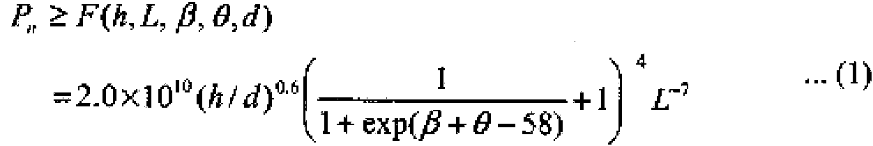
Aquí, se designa a una dirección perpendicular a la superficie de la lámina S de acero como una dirección C1 de referencia, a un ángulo formado por la dirección C1 de referencia y una dirección C3 de eyección de gas desde el puerto 112 de eyección de la boquilla 10 de ranura como un ángulo 0 [°] de eyección, a un ángulo formado por la dirección C1 de referencia y la cara 102 anterior de la boquilla como un ángulo a [°] de inclinación de cara anterior, y a un ángulo formado por la dirección C3 de eyección de gas y la cara 104 posterior de la boquilla como un ángulo b [°] de inclinación de cara posterior. Adicionalmente, se designa a una longitud de la cara 104 posterior de la boquilla en una dirección C2 de transporte de la lámina S de acero como una longitud L [mm] de cara posterior. El dispositivo 1 de retirada de líquido está configurado para satisfacer las relaciones de las ecuaciones (1) a (3) que siguen, en donde se designa a una distancia entre el puerto 112 de eyección y la superficie de la lámina S de acero como un hueco h [mm], a un grosor de abertura de ranura de la boquilla 10 de ranura mediante un grosor d [mm] de ranura, y a una presión de gas dentro de la boquilla 10 de ranura mediante una presión Pn [KPa] de boquilla.Here, a direction perpendicular to the surface of the steel sheet S is designated as a reference direction C1, an angle formed by the reference direction C1 and a gas ejection direction C3 from the ejection port 112 of the sheet. slot nozzle 10 as an angle 0 [°] of ejection, at an angle formed by the reference direction C1 and the front face 102 of the nozzle as an angle a [°] of front face inclination, and at an angle formed by the gas ejection direction C3 and the back face 104 of the nozzle as an angle b [°] of back face inclination. Additionally, a length of the back face 104 of the nozzle in a conveying direction C2 of the steel sheet S is designated as a back face length L [mm]. The liquid withdrawal device 1 is configured to satisfy the relationships of equations (1) to (3) below, wherein a distance between the ejection port 112 and the surface of the steel sheet S is designated as a gap h [mm], at a slot opening thickness of the slot nozzle 10 by a slot thickness d [mm], and at a gas pressure inside the slot nozzle 10 by a nozzle pressure Pn [KPa] .
[Mat 2][Matt 2]
P 6 > P 6 > 60° ...(2)60°...(2)
L > 20mm L > 20mm ■ ■ (3)(3)
Nótese que el ángulo 0 de eyección y el ángulo b de inclinación de cara posterior indican tamaño y poseen valores mayores o iguales a 0. En relación al ángulo a de inclinación de cara anterior, una inclinación hacia el lado aguas arriba en la dirección de transporte de la lámina S de acero y una inclinación hacia el lado aguas abajo se expresan, respectivamente, mediante un valor positivo y un valor negativo en relación a la dirección C1 de referencia que vale 0°. Adicionalmente, tal como se ilustra en la FIGURA 3, por ejemplo, la longitud L de cara posterior cuando la cara 104 posterior de boquilla no es paralela a la lámina S de acero puede calcularse mediante la fórmula L’ oos(9üe - 0 -P), donde la longitud de cara posterior propiamente dicha se designa como L’ [mm]. Por lo tanto, la longitud L de cara posterior corresponde a una longitud de la cara 104 posterior de boquilla en la dirección de transporte (dirección X) en un plano de proyección horizontal cuando la cara 104 posterior de boquilla se proyecta sobre el plano de proyección horizontal.Note that the ejection angle 0 and the rear face tilt angle b indicate size and have values greater than or equal to 0. In relation to the front face tilt angle a, an inclination towards the upstream side in the direction of transport of the steel sheet S and an inclination towards the downstream side are expressed, respectively, by a positive value and a negative value in relation to the reference direction C1 which is 0°. Additionally, as illustrated in FIGURE 3, for example, the back face length L when the nozzle back face 104 is not parallel to the steel sheet S can be calculated by the formula L' oos ( 9üe - 0 -P ), where the back face length proper is denoted L' [mm]. Therefore, the back face length L corresponds to a length of the nozzle back face 104 in the conveying direction (X direction) in a horizontal projection plane when the nozzle back face 104 is projected onto the projection plane horizontal.
(a. Relación con la presión Pn de boquilla)(a. Relation to nozzle pressure Pn)
En primer lugar, la ecuación (1) anterior expresa una condición para eliminar la influencia del flujo f4 de succión de aire exterior y eliminar la perturbación que ejerce sobre el flujo f1 de eyección de gas, que se ilustra en las FIGURAS 1 y 2. Aquí, en relación a la boquilla 10 de ranura ilustrada en la FIGURA 5, las magnitudes físicas se definen como sigue.First of all, the above equation (1) expresses a condition to eliminate the influence of the outside air suction flow f4 and eliminate the disturbance it exerts on the gas ejection flow f1, which is illustrated in FIGURES 1 and 2. Here, in relation to the slot nozzle 10 illustrated in FIGURE 5, the physical quantities are defined as follows.
‘x” indica una posición en la dirección de transporte de la lámina S de acero. Una posición de la cara 104 posterior de boquilla más lejano en el lado aguas abajo en la dirección de transporte (dirección X) de la lámina S de acero se designa como una posición de referencia (x = 0).'x' indicates a position in the transport direction of the steel sheet S. A position of the back face 104 Nozzle position farthest on the downstream side in the conveying direction (X-direction) of the steel sheet S is designated as a reference position (x = 0).
u+(x): velocidad de flujo del flujo inducido hacia el lado del puerto de eyección por el efecto Coandau+(x): flow velocity of the flow induced towards the ejection port side by the Coanda effect
u-(x): velocidad de flujo de la componente en la dirección de transporte (dirección X) de flujo de eyección de gas que ha colisionado con la lámina de acerou-(x): flow velocity of the component in the conveying direction (X direction) of gas ejection flow that has collided with the steel sheet
y(x): distancia entre la lámina de acero y la cara posterior de boquillay(x): distance between the steel sheet and the rear face of the nozzle
l : coeficiente de fricción de tuberíal : pipe friction coefficient
En la distribución de u+ en la dirección X, la velocidad de flujo disminuye desde una velocidad u+(0) inicial debido a la caída de presión al avanzar en la dirección X, en donde la velocidad u+(0) inicial tiene una magnitud del 10% de un flujo de eyección rápido basado en una experiencia anterior. Cuantitativamente, la caída de presión en función de la posición en la dirección X viene dada por la ecuación (1 -1) siguiente.In the distribution of u+ in the X direction, the flow velocity decreases from an initial velocity u+(0) due to the pressure drop moving in the X direction, where the initial velocity u+(0) has a magnitude of 10 % of fast ejection flow based on past experience. Quantitatively, the pressure drop as a function of position in the X direction is given by equation (1-1) below.
[Mat 3][Matt 3]

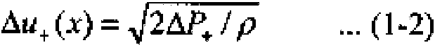
Una fluctuación de la caída de presión expresada por la ecuación (1 -1) anterior se sustituye en la ecuación (1 -2) que sigue; así, se obtiene una disminución Du+(x) de velocidad.A pressure drop fluctuation expressed by equation (1-1) above is substituted into equation (1-2) below; thus, a speed decrease Du+(x) is obtained.
[Mat 4][Matt 4]
A continuación, de acuerdo con la ecuación (1-3) que sigue, se obtiene una velocidad u+(x+dx) en una posición x+dx restando la disminución de velocidad Du+(x) obtenida de una velocidad u+(x) en la posición anteriorThen, according to equation (1-3) below, a velocity u+(x+dx) at a position x+dx is obtained by subtracting the obtained velocity decrease Du+(x) from a velocity u+(x) at the previous position
[Mat 5][Matt 5]

Por otro lado, una velocidad u-(x) de flujo de una componente en la dirección de transporte de un flujo de eyección de gas que ha colisionado con la lámina de acero puede obtenerse mediante la ecuación (1-4) que sigue utilizando una velocidad u de flujo de un flujo de eyección de gas eyectado desde la boquilla 10 de ranura.On the other hand, a flow velocity u-(x) of a component in the transport direction of an ejection flow of gas that has collided with the steel sheet can be obtained by equation (1-4) which still uses a flow velocity u of an ejection flow of gas ejected from the slot nozzle 10 .
[Mat 6][Matt 6]

Aquí, tal como se ilustra en la FIGURA 5, se lleva a cabo una discusión acerca de las magnitudes de una velocidad u+(L) de flujo de un flujo inducido hacia el puerto 112 de eyección por el efecto Coanda y una velocidad u-(L) de flujo de una componente en la dirección de transporte de un flujo de eyección de gas que ha colisionado con la lámina S de acero, en una posición separada de la posición de referencia (x=0) hacia el lado aguas arriba de la dirección de transporte por la longitud L de cara posterior de la cara 104 posterior de boquilla.Here, as illustrated in FIGURE 5, a discussion takes place about the magnitudes of a flow velocity u+(L) of a flow induced towards the ejection port 112 by the Coanda effect and a velocity u-( L) of flow of a component in the transport direction of a gas ejection flow that has collided with the steel sheet S, in a position separated from the reference position (x=0) towards the upstream side of the conveying direction by the rear face length L of the nozzle rear face 104 .
En primer lugar, un caso en el que la velocidad u+(L) de flujo es menor o igual a la velocidad u-(L) de flujo [u+(L) < u-(L)] constituye, en otras palabras, un caso en el que la velocidad u-(L) de flujo de la componente en la dirección de transporte del flujo de eyección de gas es mayor o igual a la velocidad u+(L) de flujo del flujo inducido por el efecto Coanda. Por lo tanto, el flujo f1 de eyección de gas no está influenciado por la velocidad u+(L) de flujo del flujo inducido por el efecto Coanda, y no se produce vibración. Por consiguiente, el flujo f1 de eyección de gas colisiona con la lámina S de acero sin ser perturbado, y la capacidad de drenaje de líquido del dispositivo 1 de retirada de líquido se corresponde a lo que se ilustra en la FIGURA 2.First, a case where the flow rate u+(L) is less than or equal to the flow rate u-(L) [u+(L) < u-(L)] constitutes, in other words, a case in which the flow velocity u-(L) of the component in the transport direction of the gas ejection flow is greater than or equal to the flow velocity u+(L) of the flow induced by the Coanda effect. Therefore, the gas ejection flow f1 is not influenced by the flow velocity u+(L) of the flow induced by the Coanda effect, and no vibration occurs. Therefore, the gas ejection flow f1 collides with the steel sheet S without being disturbed, and the liquid draining capacity of the liquid removing device 1 corresponds to what is illustrated in FIGURE 2.
Por otro lado, un caso en el que la velocidad u+(L) de flujo es mayor que la velocidad u-(L) de flujo [u+(L) > u-(L)] constituye, en otras palabras, un caso en el que la velocidad u+(L) de flujo del flujo inducido por el efecto Coanda es mayor que la velocidad u-(L) de flujo de la componente en la dirección de transporte del flujo de eyección de gas. En este momento, el flujo f1 de eyección de gas es influenciado por la velocidad u+(L) de flujo del flujo inducido por el efecto Coanda. Por consiguiente, el flujo f1 de eyección de gas vibra en la dirección horizontal, y la presión de colisión del flujo f1 de eyección de gas con la lámina S de acero disminuye, lo que conduce a una disminución de la capacidad de drenaje de líquido del dispositivo 1 de retirada de líquido tal como se ilustra en la FIGURA 1.On the other hand, a case where the flow rate u+(L) is greater than the flow rate u-(L) [u+(L) > u-(L)] constitutes, in other words, a case where in which the flow velocity u+(L) of the flow induced by the Coanda effect is greater than the flow velocity u-(L) of the component in the transport direction of the gas ejection flow. At this time, the gas ejection flow f1 is influenced by the flow velocity u+(L) of the flow induced by the Coanda effect. Therefore, the gas ejection flow f1 vibrates in the horizontal direction, and the collision pressure of the gas ejection flow f1 with the steel sheet S decreases, which leads to a decrease in the liquid drainage capacity of the liquid withdrawal device 1 as illustrated in FIGURE 1.
De acuerdo con la descripción anterior, la capacidad de drenaje de líquido del dispositivo 1 de retirada de líquido puede mejorarse haciendo que la velocidad u-(L) de flujo de la componente en la dirección de transporte del flujo de eyección de gas sea mayor o igual a la velocidad u+(L) de flujo del flujo inducido por el efecto Coanda. Es decir, un estado en el que la capacidad de drenaje de líquido del dispositivo 1 de retirada de líquido mejora puede conseguirse considerando el balance entre la velocidad u+ de flujo y velocidad u- de flujo en una posición de eyección de flujo de eyección de gas correspondiente a una posición x = L.According to the above description, the liquid drainability of the liquid removing device 1 can be improved by making the component flow rate u-(L) in the gas ejection flow conveying direction larger or smaller. equal to the flow velocity u+(L) of the flow induced by the Coanda effect. That is, a state in which the liquid drainability of the liquid withdrawing device 1 improves can be achieved by considering the balance between the flow rate u+ and the flow rate u- at a gas ejection flow ejection position. corresponding to a position x = L.
Por ejemplo, la FIGURA 6 muestra un ejemplo de la relación entre la velocidad u+(x) del flujo inducido hacia el lado del puerto 112 de eyección por el efecto Coanda y la velocidad u-(x) de flujo de la componente en la dirección de transporte del flujo de eyección de gas que ha colisionado con la lámina S de acero cuando la longitud L de la cara posterior tiene un valor de 20 mm y la suma del ángulo 0 de eyección y el ángulo b de inclinación de cara posterior tiene un valor de 90°. Tal como se muestra en la FIGURA 6, en una posición alejada más de 10 mm de la posición de referencia (x = 0) hacia el lado aguas arriba en la dirección de transporte, la velocidad u-(x) de flujo de la componente en la dirección de transporte del flujo de eyección de gas es mayor que la velocidad u+(x) de flujo del flujo inducido hacia el lado del puerto 112 de eyección por el efecto Coanda. Por consiguiente, en el caso en el que la longitud L de cara posterior tiene un valor de 20 mm, puesto que la velocidad u-(x) de flujo de la componente en la dirección de transporte del flujo de eyección de gas es mayor que la velocidad u+(x) de flujo del flujo inducido hacia el lado del puerto 112 de eyección por el efecto Coanda, se rectifica el flujo en la cara 104 posterior de la boquilla. For example, FIGURE 6 shows an example of the relationship between the velocity u+(x) of the flow induced towards the side of the ejection port 112 by the Coanda effect and the velocity u-(x) of the flow of the component in the direction transport of the gas ejection flow that has collided with the steel sheet S when the length L of the rear face has a value of 20 mm and the sum of the ejection angle 0 and the angle b of inclination of the rear face has a value 90° value. As shown in FIGURE 6, at a position more than 10 mm away from the reference position (x = 0) to the upstream side in the conveying direction, the flow rate u-(x) of the component in the transport direction of the gas ejection flow is greater than the flow velocity u+(x) of the flow induced towards the ejection port 112 side by the Coanda effect. Therefore, in the case where the back face length L has a value of 20 mm, since the flow velocity u-(x) of the component in the conveying direction of the gas ejection flow is greater than the flow velocity u+(x) of the flow induced towards the side of the ejection port 112 by the Coanda effect, the flow at the rear face 104 of the nozzle is rectified.
Por otro lado, por ejemplo, la FIGURA 7 muestra un ejemplo de la relación entre la velocidad u+(x) de flujo del flujo inducido hacia el lado 112 del puerto de eyección por el efecto Coanda y velocidad u-(x) de flujo de la componente en la dirección de transporte del flujo de eyección de gas que ha colisionado con la lámina S de acero cuando la longitud L de la cara posterior tiene un valor de 15 mm y suma del ángulo 0 de eyección y el ángulo b de inclinación de cara posterior tiene un valor de 50°. Tal como se muestra en la FIGURA 7, incluso en una posición alejada 15 mm de la posición de referencia (x = 0) hacia el lado aguas arriba en la dirección de transporte, la velocidad u-(x) de flujo de la componente en la dirección de transporte del flujo de eyección de gas es menor que la velocidad u+(x) de flujo del flujo inducido hacia el lado del puerto 112 de eyección por el efecto Coanda. Por lo tanto, en el caso en el que la longitud L de cara posterior tiene un valor de 15 mm, puesto que la velocidad u-(x) de flujo de la componente en la dirección de transporte del flujo de eyección de gas es menor que la velocidad u+(x) de flujo del flujo inducido hacia el lado del puerto 112 de eyección por el efecto Coanda, el flujo en la cara 104 posterior de la boquilla se vuelve turbulento, de manera que el flujo f1 de eyección de gas es perturbado.On the other hand, for example, FIGURE 7 shows an example of the relationship between the flow rate u+(x) of the flow induced towards the side 112 of the ejection port by the Coanda effect and the flow rate u-(x) of the component in the transport direction of the ejection flow of gas that has collided with the steel sheet S when the length L of the rear face has a value of 15 mm and the sum of the ejection angle 0 and the inclination angle b of back face has a value of 50°. As shown in FIGURE 7, even at a position 15 mm away from the reference position (x = 0) to the upstream side in the conveying direction, the flow velocity u-(x) of the component in the transport direction of the gas ejection flow is smaller than the flow velocity u+(x) of the flow induced towards the ejection port 112 side by the Coanda effect. Therefore, in the case where the back face length L has a value of 15 mm, since the flow velocity u-(x) of the component in the conveying direction of the gas ejection flow is smaller As the flow velocity u+(x) of the flow induced towards the ejection port 112 side by the Coanda effect, the flow at the back face 104 of the nozzle becomes turbulent, so that the gas ejection flow f1 is disturbed.
En vista de ello, los presentes inventores estudiaron una configuración y un montaje del dispositivo 1 de retirada de líquido que hacen que la velocidad u-(L) de flujo de la componente en la dirección de transporte del flujo de eyección de gas sea mayor o igual a la velocidad u+(L) de flujo del flujo inducido el efecto Coanda y, consecuentemente, llegaron a la ecuación relacional de la fórmula (1) anterior. Es decir, configurando y disponiendo la boquilla 10 de ranura de una manera en la que la presión Pn [KPa] de la boquilla 10 de ranura es mayor o igual a un valor de una ecuación F(h, L, b, 0, d) relacional que involucra al hueco h [mm], a la longitud L de cara posterior [mm], al ángulo b de inclinación de cara posterior [°], al grosor d [mm] de ranura y al ángulo 0 [°] de eyección, resulta posible la eliminación de la influencia del flujo f4 de succión de aire exterior y se suprime la perturbación en el flujo f1 de eyección de gas.In view of this, the present inventors studied a configuration and assembly of the liquid removal device 1 which makes the flow rate u-(L) of the component in the transport direction of the gas ejection flow to be higher or equal to the velocity u+(L) of flow of the flow induced by the Coanda effect and, consequently, they arrived at the relational equation of formula (1) above. That is, by configuring and arranging the slot nozzle 10 in a manner that the pressure Pn [KPa] of the slot nozzle 10 is greater than or equal to a value of an equation F(h, L, b, 0, d ) relational involving the gap h [mm], the back face length L [mm], the back face inclination angle b [°], the groove thickness d [mm] and the angle 0 [°] of ejection, it becomes possible to eliminate the influence of the outside air suction flow f4 and the disturbance in the gas ejection flow f1 is suppressed.
La ecuación F(h, L, b, 0, d) relacional puede obtenerse mediante la observación del flujo en la cara 104 posterior de boquilla de la boquilla 10 de ranura mediante un método basado en manojos de filamentos, por ejemplo, y especificando la presión Pn de boquilla para la que el flujo de la cara 104 posterior de boquilla se rectifica. La ecuación (1) anterior se estableció midiendo, mediante un método basado en manojos de filamentos, un umbral de la presión Pn de boquilla para el cual el flujo en la cara 104 posterior de boquilla se rectifica cuando el grosor d de ranura tenía un valor de 0,4 mm, y el hueco h, la longitud L de cara posterior, el ángulo b de inclinación de cara posterior y el ángulo 0 de eyección tenían valores, respectivamente, comprendidos en los intervalos entre 1 mm y 25 mm, entre 10 mm y 50 mm, entre 5° y 45°, y entre 0° y 75°, y la presión Pn de boquilla variaba gradualmente desde 5 KPa hasta 1000 KPa.The relational equation F(h, L, b, 0, d) can be obtained by observing the flow at the nozzle back face 104 of the slot nozzle 10 using a filament bundle-based method, for example, and specifying the nozzle pressure Pn for which the flow of the nozzle back face 104 is rectified. Equation (1) above was established by measuring, by a filament bundle-based method, a threshold of the nozzle pressure Pn for which the flow at the nozzle back face 104 is rectified when the groove thickness d had a value 0.4 mm, and the gap h, the back face length L, the back face tilt angle b and the ejection angle 0 had values, respectively, in the ranges between 1 mm and 25 mm, between 10 mm and 50 mm, between 5° and 45°, and between 0° and 75°, and the nozzle pressure Pn gradually varied from 5 KPa to 1000 KPa.
Específicamente, el flujo en la cara 104 posterior de boquilla se visualizó disponiendo filamentos de polietileno con un diámetro de 0,025 mm y una longitud de 3 mm en la cara 104 posterior de boquilla distanciados 5 mm entre sí a lo largo de la dirección de transporte de la lámina S de acero, y se permitió que los filamentos fuesen movidos por el flujo en la cara 104 posterior de boquilla que cambia de acuerdo con la presión Pn de boquilla. Cuando todos los filamentos situados en la cara 104 posterior de boquilla se orientaron en la dirección de transporte de la lámina S de acero, se determinó que el flujo en la cara 104 posterior de boquilla se había rectificado, y la presión Pn de boquilla en este instante se tomó como el valor umbral. A continuación, se obtuvo la ecuación (1) anterior llevando a cabo un análisis de regresión múltiple multivariable con el hueco h, la longitud L de cara posterior, el ángulo b de inclinación de cara posterior, y el ángulo 0 de eyección, en relación a cada uno de los umbrales de la presión Pn de boquilla obtenida haciendo variar el hueco h, la longitud L de cara posterior, el ángulo b de inclinación de cara posterior y el ángulo 0 de eyección.Specifically, the flow on the nozzle back face 104 was visualized by arranging polyethylene filaments with a diameter of 0.025 mm and a length of 3 mm on the nozzle back face 104 spaced 5 mm apart along the direction of transport of the nozzle. the steel sheet S, and the filaments were allowed to be moved by the flow at the nozzle back face 104 which changes according to the nozzle pressure Pn. When all the filaments located at the nozzle back face 104 were oriented in the transport direction of the steel sheet S, it was determined that the flow at the nozzle back face 104 had been rectified, and the nozzle pressure Pn at this instant was taken as the threshold value. Next, the above equation (1) was obtained by performing a multivariate multiple regression analysis with the gap h, backface length L, backface tilt angle b, and ejection angle 0, relative to at each of the thresholds of the nozzle pressure Pn obtained by varying the gap h, the length L of the rear face, the angle b of inclination of the rear face and the ejection angle 0.
En el caso en el que el valor dado por la ecuación F(h, L, b, 0, d) relacional de la ecuación (1) obtenido mediante este método es menor o igual a la presión Pn de boquilla de la boquilla 10 de ranura, la velocidad u-(L) de flujo de la componente en la dirección de transporte del flujo de eyección de gas es mayor o igual a la velocidad u+(L) de flujo del flujo inducido por el efecto Coanda. En este instante, el flujo f1 de eyección de gas colisiona con la lámina S de acero sin ser perturbado, y el dispositivo 1 de retirada de líquido mejora su capacidad de drenaje de líquido. Por lo tanto, configurando el dispositivo 1 de retirada de líquido para que satisfaga la ecuación (1) anterior hace posible retirar líquido de la lámina S de acero.In the case where the value given by the relational equation F(h, L, b, 0, d) of equation (1) obtained by this method is less than or equal to the nozzle pressure Pn of nozzle 10 of slot, the flow velocity u-(L) of the component in the transport direction of the gas ejection flow is greater than or equal to the flow velocity u+(L) of the flow induced by the Coanda effect. At this time, the gas ejection flow f1 collides with the steel sheet S without being disturbed, and the liquid removing device 1 improves its liquid drainage ability. Therefore, configuring the liquid removing device 1 to satisfy the above equation (1) makes it possible to remove liquid from the steel sheet S.
Adicionalmente, el hueco h, la longitud L de cara posterior, el ángulo b de inclinación de cara posterior y el ángulo 0 de eyección se establecen tal como se explica a continuación.Additionally, the gap h, back face length L, back face tilt angle b, and ejection angle 0 are set as explained below.
(b. Ángulo 0 de eyección y ángulo b de inclinación de cara posterior)(b. Ejection angle 0 and back face tilt angle b)
El ángulo 0 de eyección y el ángulo b de inclinación de cara posterior se establecen de una manera tal que su suma es mayor o igual a 60°, tal como se expresa en la ecuación (2) anterior. La suma del ángulo 0 de eyección y el ángulo b de inclinación de cara posterior indica un estado de inclinación de la cara 104 posterior de boquilla en relación a la dirección C1 de referencia. Cuando la suma del ángulo 0 de eyección y el ángulo b de inclinación de cara posterior es de 90°, la cara 104 posterior de boquilla es paralela a la superficie de la lámina S de acero. Si la suma del ángulo 0 de eyección y el ángulo b de inclinación de cara posterior es menor de 60°, se produce interferencia entre el flujo f4 de succión de aire exterior y el flujo f3 inverso después de la colisión con la superficie de la lámina S de acero, provocando una disminución en la presión de colisión del flujo f1 de eyección de gas, de tal manera que el líquido 5a en la superficie de la lámina S de acero no puede ser retirado. Por lo tanto, la suma del ángulo 0 de eyección y el ángulo b de inclinación de cara posterior se establece en un valor mayor o igual a 60°. Nótese que el límite superior para la suma del ángulo 0 de eyección y el ángulo b de inclinación de cara posterior es un valor máximo en un intervalo dentro del cual la cara 104 posterior de boquilla todavía no entra en contacto con la superficie de la lámina S de acero.The ejection angle 0 and the back face tilt angle b are set in such a way that their sum is greater than or equal to 60°, as expressed in equation (2) above. The sum of the ejection angle 0 and the back face tilt angle b indicates a state of tilt of the nozzle back face 104 relative to the reference direction C1. When the sum of the ejection angle 0 and the back face tilt angle b is 90°, the nozzle back face 104 is parallel to the surface of the steel sheet S. If the sum of the ejection angle 0 and the back face tilt angle b is less than 60°, interference occurs between the outside air suction flow f4 and the reverse flow f3 after the collision with the sheet surface. S of steel, causing a decrease in the collision pressure of the gas ejection flow f1, such that the liquid 5a on the surface of the steel sheet S cannot be removed. Therefore, the sum of the ejection angle 0 and the back face tilt angle b is set to a value greater than or equal to 60°. Note that the upper limit for the sum of the ejection angle 0 and the back face tilt angle b is a maximum value in an interval within which the nozzle back face 104 does not yet come into contact with the sheet surface S of steel.
La cara 104 posterior de boquilla está preferiblemente dispuesta de manera que es paralela a la superficie de la lámina S de acero; es decir, que la suma del ángulo 0 de eyección y el ángulo b de inclinación de cara posterior se establece preferiblemente en un valor de 90°. Por lo tanto, después de que el flujo f1 de eyección de gas colisione con la superficie de la lámina S de acero, el flujo f3 inverso hacia el lado aguas abajo en la dirección de transporte de la lámina S de acero puede fluir de manera suave entre la cara 104 posterior de boquilla y la superficie de la lámina S de acero.The rear nozzle face 104 is preferably arranged so that it is parallel to the surface of the steel sheet S; that is, the sum of the ejection angle 0 and the back face tilt angle b is preferably set to a value of 90°. Therefore, after the gas ejection flow f1 collides with the surface of the steel sheet S, the reverse flow f3 to the downstream side in the conveying direction of the steel sheet S can flow smoothly. between the nozzle rear face 104 and the surface of the steel sheet S.
Adicionalmente, el ángulo 0 de eyección de gas se establece preferiblemente en un valor de 45°. Por lo tanto, el gas eyectado desde el puerto 112 de eyección de la boquilla 10 de ranura puede colisionar con un ángulo de 45° desde el lado aguas abajo en la dirección de transporte con respecto a la superficie de la lámina S de acero, y puede empujar hacia atrás de manera efectiva el líquido 5a en la superficie de la lámina S de acero hacia el lado aguas arriba en la dirección de transporte para retirarlo. Tomando en consideración que la suma del ángulo 0 de eyección y el ángulo b de inclinación de cara posterior tiene preferiblemente un valor de 90°, el ángulo 0 de eyección y el ángulo b de inclinación de cara posterior se fijan preferiblemente, cada uno de ellos, a un valor de 45°.Additionally, the gas ejection angle 0 is preferably set to a value of 45°. Therefore, the gas ejected from the ejection port 112 of the slot nozzle 10 may collide at an angle of 45° from the downstream side in the conveying direction with respect to the surface of the steel sheet S, and it can effectively push back the liquid 5a on the surface of the steel sheet S to the upstream side in the conveying direction to remove it. Taking into consideration that the sum of the ejection angle 0 and the back face tilt angle b preferably has a value of 90°, the ejection angle 0 and the back face tilt angle b are preferably each set , at a value of 45°.
(c. Longitud L de cara posterior)(c. Back face length L)
La longitud L de cara posterior de la cara 104 posterior de boquilla se establece en un valor mayor o igual a 20 mm, tal como se muestra en la ecuación (3). Si la longitud L de cara posterior es menor que 20 mm, el flujo f4 de succión de aire exterior y el flujo f3 inverso colisionan entre sí en la vecindad del flujo f1 de eyección de gas para perturbar al flujo f1 de eyección de gas. Por lo tanto, estableciendo la longitud L de cara posterior en un valor mayor o igual a 20 mm se evita que el flujo f4 de succión de aire exterior y el flujo f3 inverso colisionen en la vecindad del flujo f1 de eyección de gas, y elimina la perturbación en el flujo f1 de eyección de gas provocada por el flujo f4 de succión de aire exterior. Adicionalmente, estableciendo la longitud L de cara posterior en un valor mayor o igual a 20 mm, se provoca una disminución en la presión del flujo f3 inverso antes de la colisión del flujo f4 de succión de aire exterior, lo que hace más pequeña la perturbación en el aire cuando el flujo f4 de succión de aire exterior y el flujo f3 inverso colisionan entre sí. Haciendo que la longitud L de cara posterior tenga un valor mayor, también se consigue que resulte menos probable que el flujo f4 de succión de aire exterior entre en una zona situada entre la cara 104 posterior de la boquilla y la superficie de la lámina S de acero. Por lo tanto, la longitud L de cara posterior se establece preferiblemente en un valor mayor o igual a 20 mm.The rear face length L of the nozzle rear face 104 is set to a value greater than or equal to 20 mm, as shown in equation (3). If the back face length L is less than 20 mm, the outside air suction flow f4 and the reverse flow f3 collide with each other in the vicinity of the gas ejection flow f1 to disturb the gas ejection flow f1. Therefore, setting the back face length L to a value greater than or equal to 20mm prevents outside air suction flow f4 and reverse air flow f3 from colliding in the vicinity of gas ejection flow f1, and eliminates the disturbance in the gas ejection flow f1 caused by the outside air suction flow f4. Additionally, setting the back face length L to a value greater than or equal to 20 mm causes a decrease in the pressure of the reverse flow f3 before the collision of the outside air suction flow f4, which makes the disturbance smaller. in the air when the outside air suction flow f4 and the reverse flow f3 collide with each other. By making the rear face length L larger, it is also made less likely that the outside air suction flow f4 will enter an area between the rear face 104 of the nozzle and the surface of the sheet S of the nozzle. steel. Therefore, the back face length L is preferably set to a value greater than or equal to 20 mm.
Nótese que un límite superior de la longitud L de cara posterior de la cara 104 posterior de la boquilla no está particularmente limitado, siempre que no se lleve a cabo ningún contacto con otro elemento, en cuanto al equipo. Por ejemplo, la longitud L de cara posterior puede tener un valor tan grande como 100 mm.Note that an upper limit of the rear face length L of the rear face 104 of the nozzle is not particularly limited, as long as no contact with another element is carried out, equipment-wise. For example, the back face length L can have a value as large as 100 mm.
(d. Hueco h)(d. Hollow h)
El hueco h, que es la distancia entre el puerto 112 de eyección y la superficie de la lámina S de acero, se establece preferiblemente de una manera tal que el puerto 112 de eyección se sitúa en un lugar tan cercano como sea posible a la lámina S de acero justamente hasta el punto de no entrar en contacto con la lámina S de acero, tal como se describió anteriormente. Esto puede hacer que el gas eyectado desde la boquilla 10 de ranura fluya hacia el interior de un espacio situado entre la cara posterior de boquilla de la boquilla 10 de ranura y la lámina S de acero, posibilitando la eliminación de la influencia del flujo f4 de succión de aire exterior y el flujo f1 de eyección de gas, tal como se ilustra en la FIGURA 2. Para conseguir esto, el hueco h se establece preferiblemente en un valor menor o igual a 20 mm, por ejemplo.The gap h, which is the distance between the ejection port 112 and the surface of the steel sheet S, is set preferably in such a way that the ejection port 112 is located as close as possible to the steel sheet S just to the point of not contacting the steel sheet S, as described above. This can cause the gas ejected from the slot nozzle 10 to flow into a space between the nozzle rear face of the slot nozzle 10 and the steel sheet S, making it possible to eliminate the influence of the flux f4 of outside air suction and gas ejection flow f1, as illustrated in FIGURE 2. To achieve this, the gap h is preferably set to a value less than or equal to 20 mm, for example.
Nótese que el ángulo a de inclinación de cara anterior no está particularmente limitado, pero puede establecerse en un valor menor o igual a 30°. Si el ángulo a de inclinación de cara anterior es mayor de 30°, la cara 102 de cara anterior de boquilla está inclinada excesivamente hacia el lado aguas arriba en la dirección de transporte; por lo tanto, después de que el flujo f1 de eyección de gas colisiona con la superficie de la lámina S de acero, resulta probable que el flujo f2 hacia el lado aguas arriba en la dirección de transporte se convierta en un flujo orientado hacia el puerto 112 de eyección de la boquilla 10 de ranura de nuevo a lo largo de la cara 102 anterior de la boquilla, sin orientarse hacia el lado aguas arriba como lo está. Cuando se forma un flujo tal, disminuye el rendimiento de retirada de líquido 5a de la superficie de la lámina S de acero por parte del flujo f2. Por lo tanto, para evitar una disminución en el rendimiento de retirada de líquido, el ángulo a de inclinación de cara anterior puede establecerse en un valor menor o igual a 30°. Resulta preferible que el ángulo a de inclinación de la cara anterior tenga un valor menor o igual a 0°. Esto hace posible evitar de manera más fiable que el flujo f2 hacia el lado aguas arriba en la dirección de transporte se convierta en un flujo orientado hacia el puerto 112 de eyección de la boquilla 10 de ranura de nuevo a lo largo de la cara 102 anterior de la boquilla.Note that the angle of inclination of front face is not particularly limited, but can be set to a value less than or equal to 30 °. If the angle of inclination of front face is greater than 30 °, the face 102 of above nozzle face is excessively inclined toward the upstream side in the conveying direction; therefore, after the gas ejection flow f1 collides with the surface of the steel sheet S, it is likely that the flow f2 to the upstream side in the conveying direction will become a port-oriented flow Ejection 112 of the slot nozzle 10 back along the front face 102 of the nozzle, not facing the upstream side as it is. When such a flow is formed, the removal efficiency of liquid 5a from the surface of the steel sheet S by the flow f2 decreases. Therefore, to avoid a decrease in performance liquid removal, the angle of inclination of front face be set to a value less than or equal to 30 °. It is preferable that the angle of inclination of the front face has a value less than or equal to 0 °. This makes it possible to more reliably prevent the flow f2 towards the upstream side in the conveying direction from becoming a flow facing the ejection port 112 of the slot nozzle 10 again along the front face 102 . of the mouthpiece.
De acuerdo con la descripción anterior, la boquilla 10 de ranura se configura y se dispone con el fin de que satisfaga las ecuaciones (1) a (3) anteriores. Esto puede reducir la perturbación en el flujo f1 de eyección de gas producido por la colisión entre el flujo f4 de succión de aire exterior y el flujo f3 inverso, evitándose una disminución en la presión de colisión cuando el flujo f1 de eyección de gas colisiona con la superficie de la lámina S de acero, y permitiéndose que la presión del flujo f2 hacia el lado aguas arriba en la dirección del transporte se mantenga. Consecuentemente, el líquido 5a en la lámina S de acero puede ser retirado suficientemente. El dispositivo 1 de retirada de líquido de acuerdo con la presente realización puede retirar líquido de manera suficiente en una lámina de acero sin utilizar ni rodillos escurridores ni una secadora, y por lo tanto puede reducir el coste de mantenimiento del equipo.In accordance with the above description, the slot nozzle 10 is configured and arranged so as to satisfy equations (1) to (3) above. This can reduce the disturbance in the gas ejection flow f1 caused by the collision between the outside air suction flow f4 and the reverse flow f3, avoiding a drop in collision pressure when the gas ejection flow f1 collides with the surface of the steel sheet S, and allowing the flow pressure f2 to the upstream side in the conveying direction to be maintained. Consequently, the liquid 5a in the steel sheet S can be sufficiently removed. The liquid removing device 1 according to the present embodiment can sufficiently remove liquid in a steel sheet without using either squeegee rollers or a dryer, and thus can reduce the maintenance cost of the equipment.
La FIGURA 8 muestra la relación entre el hueco h y la presión Pn calculada mediante la ecuación (1) anterior cuando el ángulo 0 de eyección se establece en un valor de 45° y se varían el ángulo b de inclinación de cara posterior y la longitud L de cara posterior. La presión Pn de boquilla mostrada en la FIGURA 8 indica un umbral cuando se determina que el flujo en la cara 104 posterior de la boquilla está rectificado de acuerdo con el método basado en manojos de filamentos descrito anteriormente, y es un valor que corresponde a cuando ambos miembros de la ecuación (1) tienen el mismo valor [ Pn = F(h, L, b, 0, d)]. Es decir, las curvas de la gráfica correspondientes a los casos “a” a “f” en la FIGURA 8 indican, cada una de ellas, la frontera entre una región en la que el flujo en la cara 104 posterior de la boquilla se rectifica y una región en la que el flujo de la cara 104 posterior de la boquilla se hace turbulento. Tal como se muestra en la FIGURA 9, en la curva de la gráfica o en el lado superior en relación a la curva de la gráfica, la presión Pn de la boquilla es mayor o igual al valor dado por la ecuación F(h, L, b, 0, d) relacional, satisfaciendo la relación de la ecuación (1) anterior; por lo tanto, el flujo en la cara 104 posterior de la boquilla se rectifica. Por otro lado, en el lado inferior en relación a la curva de la gráfica, la presión Pn de la boquilla es menor que el valor dado por la ecuación F(h, L, b, 0, d) relacional, no satisfaciendo la relación de la ecuación (1) anterior. Consecuentemente, el flujo en la cara 104 posterior de la boquilla se hace turbulento, y el flujo f1 de eyección de gas es perturbado.FIGURE 8 shows the relationship between the gap h and the pressure Pn calculated by equation (1) above when the ejection angle 0 is set to a value of 45° and the back face tilt angle b and length L are varied. rear face. The nozzle pressure Pn shown in FIGURE 8 indicates a threshold when the flow at the nozzle back face 104 is determined to be rectified according to the filament bundle-based method described above, and is a value corresponding to when both sides of equation (1) have the same value [ Pn = F(h, L, b, 0, d)]. That is, the curves of the graph corresponding to the cases "a" to "f" in FIGURE 8 indicate, each of them, the border between a region in which the flow on the rear face 104 of the nozzle is rectified and a region in which the flow from the back face 104 of the nozzle becomes turbulent. As shown in FIGURE 9, on the graph curve or on the upper side relative to the graph curve, the nozzle pressure Pn is greater than or equal to the value given by the equation F(h, L , b, 0, d) relational, satisfying the relation of equation (1) above; therefore, the flow at the rear face 104 of the nozzle is rectified. On the other hand, on the lower side relative to the graph curve, the nozzle pressure Pn is less than the value given by the relational equation F(h, L, b, 0, d), not satisfying the relation from equation (1) above. Consequently, the flow at the rear face 104 of the nozzle becomes turbulent, and the gas ejection flow f1 is disturbed.
En la FIGURA 8, la suma del ángulo b de inclinación de cara posterior y el ángulo 0 de eyección es de 90° en los casos “a” a “c” y de 60° en los casos “d” a “f”, satisfaciendo ambos la ecuación (2) anterior. La longitud L de cara posterior tiene un valor de 25 mm o de 20 mm en los casos “a”, “b”, “d” y “e”, satisfaciendo la ecuación (3) anterior, pero tiene un valor de 15 mm en los casos “c” y “f”, no satisfaciendo la ecuación (3) anterior. Tal como se muestra en la FIGURA 8, las curvas de la gráfica de los casos “c” y “f” que no satisfacen la ecuación (3) anterior tienen pendientes mayores que las curvas de la gráfica en los casos “a”, “b”, “d” y “e”, que sí satisfacen la ecuación (3) anterior, y se necesita una presión Pn de boquilla mayor o igual a 200 KPa incluso en el caso en el que el hueco h es tan pequeño como 3 mm. Si se requiere una presión Pn mayor o igual a 200 KPa, no puede garantizarse la presión y el dispositivo 1 de retirada de líquido no podrá instalarse dependiendo de la situación de la instalación de tuberías en una fábrica, o incluso si el dispositivo 1 de retirada de líquido puede instalarse, se asume que se necesitará un caudal de flujo de aire muy elevado, conllevando un aumento en el coste, por ejemplo. Por lo tanto, la longitud L de la cara posterior se establece preferiblemente en un valor mayor o igual a 20 mm.In FIGURE 8, the sum of the angle b of inclination of the rear face and the angle 0 of ejection is 90° in cases “a” to “c” and 60° in cases “d” to “f”, both satisfying equation (2) above. The length L of the rear face has a value of 25 mm or 20 mm in cases "a", "b", "d" and "e", satisfying equation (3) above, but it has a value of 15 mm in cases "c" and "f", not satisfying equation (3) above. As shown in FIGURE 8, the curves on the graph for cases “c” and “f” that do not satisfy equation (3) above have steeper slopes than the curves on the graph for cases “a”, “ b”, “d” and “e”, which do satisfy equation (3) above, and a nozzle pressure Pn greater than or equal to 200 KPa is needed even in the case where the gap h is as small as 3 mm. If a pressure Pn greater than or equal to 200 KPa is required, the pressure cannot be guaranteed, and the liquid withdrawal device 1 may not be installed depending on the situation of piping installation in a factory, or even if the liquid withdrawal device 1 of liquid can be installed, it is assumed that a very high airflow rate will be needed, leading to an increase in cost, for example. Therefore, the back face length L is preferably set to a value greater than or equal to 20 mm.
Por otro lado, las curvas de la gráfica de los casos “a”, “b”, “d” y “e” tienen pendientes similares, y la ecuación (1) anterior puede satisfacerse incluso si el hueco h es grande o si la presión Pn de boquilla de la boquilla 10 de ranura se establece en un valor inferior a 200 KPa. Nótese que en el caso en el que la longitud L de cara posterior sea la misma, un valor mayor de la suma del ángulo b de inclinación de cara posterior y el ángulo 0 de eyección puede hacer disminuir el valor de la presión Pn de boquilla requerida.On the other hand, the graph curves of cases “a”, “b”, “d” and “e” have similar slopes, and equation (1) above can be satisfied even if the gap h is large or if the Nozzle pressure Pn of the slot nozzle 10 is set to a value less than 200KPa. Note that in the case where the back face length L is the same, a larger value of the sum of the back face tilt angle b and the ejection angle 0 can decrease the value of the required nozzle pressure Pn.
Tal como se describió anteriormente, la boquilla 10 de ranura está configurada y dispuesta de tal manera que satisface las ecuaciones (1) a (3) anteriores; por lo tanto, el flujo en la cara 104 posterior de boquilla puede ser rectificado y puede evitarse que influencie la circulación del flujo f1 de eyección de gas. Por consiguiente, puede conseguirse un dispositivo de retirada de líquido capaz de garantizar la versatilidad de la presión de aire y que posea un caudal de flujo de aire económico.As described above, the slot nozzle 10 is configured and arranged such that it satisfies equations (1) through (3) above; therefore, the flow at the nozzle back face 104 can be rectified and can be prevented from influencing the flow of the gas ejection flow f1. Accordingly, a liquid removal device capable of ensuring versatility of air pressure and having an economical air flow rate can be provided.
(2-3. Ejemplo de modificación)(2-3. Modification example)
La boquilla 10 de ranura del dispositivo 1 de retirada de líquido ilustrado en la FIGURA 5 ilustra un caso en el que se fabrica una forma externa de la boquilla propiamente dicha con el fin de satisfacer las ecuaciones (1) a (3) anteriores, pero la presente invención no está limitada a este ejemplo. Por ejemplo, tal como se ilustra en la FIGURA 10, la boquilla 10 de ranura del dispositivo 1 de retirada de líquido puede incluir una boquilla 210 de ranura (a la que se hará referencia de ahora en adelante como “cuerpo principal de boquilla”) que posee una forma externa axisimétrica que se utiliza comúnmente, y un elemento 220 de cara posterior. El cuerpo 210 principal de boquilla posee un puerto 216 de eyección, que está constituido por una ranura a través de la cual se eyecta gas. Una cara 212 anterior del cuerpo principal de boquilla y una cara 214 posterior de cuerpo principal de boquilla son simétricas con respecto a la dirección C3 de eyección de gas. El elemento 220 de cara posterior es, por ejemplo, un elemento de tipo lámina tal como una lámina de acero. El elemento 220 de cara posterior está conectado a la cara 214 posterior del cuerpo principal de boquilla, y constituye una cara posterior de boquilla que se extiende desde el puerto 216 de eyección del cuerpo 210 principal de boquilla hacia el lado aguas abajo en la dirección de transporte de la lámina S de acero. Es decir, una contracara del elemento 220 de cara posterior que mira hacia la superficie de la lámina S de acero sirve como una cara posterior de boquilla.The slot nozzle 10 of the liquid withdrawing device 1 illustrated in FIGURE 5 illustrates a case where an external shape of the nozzle itself is made in order to satisfy equations (1) to (3) above, but the present invention is not limited to this example. For example, as illustrated in FIGURE 10, the slot nozzle 10 of the liquid withdrawal device 1 may include a slot nozzle 210 (hereinafter referred to as the "nozzle main body"). having a commonly used axisymmetric external shape, and a back face element 220. The nozzle main body 210 has an ejection port 216, which is constituted by a slot through which gas is ejected. A nozzle main body front face 212 and a nozzle main body rear face 214 are symmetrical with respect to the gas ejection direction C3. Back face member 220 is, for example, a sheet-like member such as a steel sheet. The back face member 220 is connected to the back face 214 of the nozzle main body, and constitutes a back face of the nozzle that extends from the ejection port 216 of the nozzle main body 210 to the downstream side in the direction of flow. transportation of the steel sheet S. That is, a counter face of the back face member 220 facing the surface of the steel sheet S serves as a nozzle back face.
También en el caso de una boquilla 10 de ranura tal, se satisfacen las ecuaciones (1) a (3) anteriores, y se proporciona una cara 222 inferior del elemento 220 de cara posterior que funciona como una cara posterior de boquilla y se extiende a lo largo de la superficie de la lámina S de acero hacia el lado aguas abajo en la dirección de transporte. Tal como ocurría con la boquilla 10 de ranura ilustrada en la FIGURA 5, esto puede reducir la perturbación en el flujo f1 de eyección de gas producida por la colisión entre el flujo f4 de succión de aire externo y el flujo f3 inverso, evitando una disminución en la presión de colisión cuando el flujo f1 de eyección de gas colisiona con la superficie de la lámina S de acero, y permitiendo que se mantenga la presión del flujo f2 hacia el lado aguas arriba en la dirección de transporte; por lo tanto, el líquido 5a en la lámina S de acero puede ser retirado suficientemente.Also in the case of such a slot nozzle 10, equations (1) to (3) above are satisfied, and a bottom face 222 of back face element 220 is provided which functions as a nozzle back face and extends to along the surface of the steel sheet S to the downstream side in the conveying direction. As was the case with the slot nozzle 10 illustrated in FIGURE 5, this can reduce the disturbance in the gas ejection flow f1 caused by the collision between the external air suction flow f4 and the reverse flow f3, avoiding a decrease in the collision pressure when the gas ejection flow f1 collides with the surface of the steel sheet S, and allowing the pressure of the flow f2 to be maintained towards the upstream side in the conveying direction; therefore, the liquid 5a in the steel sheet S can be sufficiently removed.
La configuración ilustrada en la FIGURA 10 puede implementarse proporcionando el elemento 220 de cara posterior en el cuerpo 210 principal de boquilla, que es una boquilla de ranura existente, requiriéndose pocos cambios en el equipamiento existente. Un dispositivo de retirada de líquido con una configuración tal también puede proporcionar un efecto de retirar líquido en la superficie de la lámina S de acero de manera suficiente.The configuration illustrated in FIGURE 10 can be implemented by providing the back face element 220 on the nozzle main body 210, which is an existing slot nozzle, with few changes to existing equipment being required. A liquid removing device with such a configuration can also provide a liquid removing effect on the surface of the steel sheet S sufficiently.
<3. Método de retirada de líquido><3. Liquid Withdrawal Method>
El líquido adherido a la superficie de la lámina S de acero puede retirarse haciendo que la boquilla 10 de ranura del dispositivo 1 de retirada de líquido descrito anteriormente mire hacia la superficie de la lámina S de acero y eyectando gas desde la boquilla 10 de ranura hacia la superficie de la lámina S de acero. En este instante, en primer lugar, se mide un hueco existente entre el puerto 112 de eyección de la boquilla 10 de ranura y lámina S de acero por parte del dispositivo 30 de medida de hueco. Entonces, el hueco se ajusta a un valor menor o igual a 20 mm cambiando, mediante el accionamiento de la sección de accionamiento del mecanismo 40 de ajuste de hueco, una posición de al menos un elemento de entre la boquilla 10 de ranura y la lámina S de acero sobre la base del hueco medido. A continuación, el líquido adherido a la superficie de la lámina S de acero puede retirarse mediante la eyección de gas desde la boquilla 10 de ranura hacia la superficie de la lámina S de acero mientras se desplazan en términos relativos la boquilla 10 de ranura y la lámina S de acero.The liquid adhered to the surface of the steel sheet S can be removed by making the slot nozzle 10 of the above-described liquid removing device 1 face the surface of the steel sheet S and ejecting gas from the slot nozzle 10 towards the surface of the steel sheet S. the surface of the steel sheet S. At this time, first, a gap between the ejection port 112 of the slot nozzle 10 and steel sheet S is measured by the gap measuring device 30. Then, the gap is adjusted to a value less than or equal to 20 mm by changing, by driving the drive section of the gap adjustment mechanism 40, a position of at least one element between the slot nozzle 10 and the sheet. S steel based on measured gap. Then, the liquid adhered to the surface of the steel sheet S can be removed by blowing gas from the slot nozzle 10 towards the surface of the steel sheet S while moving the slot nozzle 10 and the slot nozzle 10 relative to each other. steel sheets.
Nótese que la medida de hueco por parte del dispositivo 30 de medida de hueco y el ajuste de hueco por parte del mecanismo 40 de ajuste de hueco pueden llevarse a cabo para cada lámina S de acero diferente que deba ser procesada. Alternativamente, en el caso en el que cambie el grosor de la lámina mientras la lámina S de acero está siendo desplazada, también cambiaría una onda de borde de un borde de la lámina, y también cambiaría un tamaño permitido de hueco. Por lo tanto, el hueco puede ser medido por el dispositivo 30 de medida de hueco en tiempo real mientras se desplaza la lámina S de acero, y el hueco puede ajustarse a un valor menor o igual a 20 mm mediante el mecanismo 40 de ajuste de hueco sobre la base del valor de medición de hueco adquirido.Note that the gap measurement by the gap measuring device 30 and the gap setting by the gap setting mechanism 40 can be carried out for each different steel sheet S to be processed. Alternatively, in the case where the thickness of the sheet changes while the steel sheet S is being displaced, an edge wave of an edge of the sheet would also change, and an allowable gap size would also change. Therefore, the gap can be measured by the gap measuring device 30 in real time while the steel sheet S is moving, and the gap can be adjusted to a value less than or equal to 20mm by the gap adjustment mechanism 40. gap based on the acquired gap measurement value.
[Ejemplos][Examples]
En relación a una boquilla de ranura utilizada por un dispositivo de retirada de líquido de la presente invención, se ha verificado un efecto de drenaje de líquido consistente en la retirada de líquido en la superficie de una lámina de acero. En esta verificación, el dispositivo de retirada de líquido de acuerdo con la presente invención se instaló detrás de un equipo de limpieza de una línea de procesamiento de lámina de acero continua, y se midió un grosor de la película del líquido que permanecía en la superficie de la lámina de acero después de la retirada de líquido de la superficie de la lámina de acero por parte del dispositivo de retirada de líquido. No se utilizaron ni rodillos escurridores ni una secadora. En este punto, se estableció la velocidad lineal de la lámina de acero en 100 mpm, el hueco se fijó en 3 mm, el ángulo 0 de eyección se fijó en 45° y el grosor d de ranura se fijó en 0,4 mm.Regarding a slot nozzle used by a liquid removal device of the present invention, a liquid drainage effect consisting of liquid removal on the surface of a steel sheet has been verified. In this verification, the liquid removal device according to the present invention was installed behind a cleaning equipment of a continuous steel sheet processing line, and a film thickness of the liquid remaining on the surface was measured. of the steel sheet after removal of liquid from the surface of the steel sheet by the liquid removal device. Neither squeegee rollers nor a dryer were used. At this point, the linear speed of the steel sheet was set to 100 mpm, the gap was set to 3 mm, the ejection angle 0 was set to 45°, and the groove thickness d was set to 0.4 mm.
A continuación, se investigó la relación entre la longitud L de cara posterior de la cara posterior de la boquilla y el grosor de la película del líquido que permanecía en la superficie de la lámina de acero, habiéndose establecido el ángulo a de inclinación de cara anterior en un valor de 30°, en relación con casos en los que el ángulo b de inclinación de cara posterior se estableció en 10°, 15°, 45° (es decir, 0 b = 55°, 60°, 90°) y con casos en los que la presión Pn de boquilla se estableció en 90 KPa, 150 KPa. Los resultados se muestran en la FIGURA 11 y en la Tabla 1. En esta verificación, en relación a seis combinaciones del ángulo b de inclinación de cara posterior y la presión Pn de boquilla de los casos A a F, se evaluó un efecto de drenaje de líquido cuando se varió la longitud L de cara posterior. En la Tabla 1 más abajo, los indicadores numéricos “-1”, “-2” y “-3” de los casos A a F indican, respectivamente, casos en los que la longitud L de cara posterior tenía un valor de 15 mm, 20 mm, 25 mm.Next, the relationship between the back face length L of the back face of the nozzle and the film thickness of the liquid remaining on the surface of the steel sheet was investigated, having established the front face inclination angle a at a value of 30°, relative to cases where the backface tilt angle b was set to 10°, 15°, 45° (i.e. 0 b = 55°, 60°, 90°) and with cases where the nozzle pressure Pn was set to 90 KPa, 150 KPa. The results are shown in FIGURE 11 and Table 1. In this verification, in relation to six combinations of the back face tilt angle b and the nozzle pressure Pn of cases A to F, a drainage effect was evaluated of liquid when the length L of the back face was varied. In Table 1 below, numerical indicators "-1", "-2" and "-3" of cases A to F indicate, respectively, cases in which the back face length L had a value of 15 mm , 20mm, 25mm
En esta verificación, se evaluó un efecto de drenaje de líquido de acuerdo con el grosor de la película del líquido que permanecía después de la retirada de líquido en la superficie de la lámina de acero por parte del dispositivo de retirada de líquido. En funcionamiento, el drenaje de líquidos se evalúa mediante inspección visual. Normalmente, tal como se muestra en la FIGURA 13, la permanencia del líquido se reconoce de manera visual cuando el grosor de la película de líquido sobre la superficie de la lámina de acero es mayor o igual a 0,5 pm; en ese caso, se determina que la superficie de la lámina de acero tiene un fallo de calidad. Por consiguiente, se evaluó que se había obtenido un efecto de drenaje de líquido cuando el grosor de la película de líquido sobre la superficie de la lámina de acero era menor que 0,5 pm. En la Tabla 1, “efecto de drenaje de líquido: SÍ (O)” indica un caso en el que el grosor de la película de líquido sobre la superficie de la lámina de acero era inferior a 0,5 pm, y “efecto de drenaje de líquido: NO (X)” indica un caso en el que el grosor de la película de líquido sobre la superficie de la lámina de acero era mayor o igual a 0,5 pm.In this verification, a liquid drainage effect was evaluated according to the film thickness of the liquid remaining after liquid removal on the surface of the steel sheet by the liquid removal device. In operation, liquid drainage is evaluated by visual inspection. Normally, as shown in FIGURE 13, liquid permanence is recognized visually when the thickness of the liquid film on the surface of the steel sheet is greater than or equal to 0.5 pm; in that case, it is determined that the surface of the steel sheet has a quality failure. Accordingly, it was evaluated that a liquid drainage effect was obtained when the thickness of the liquid film on the surface of the steel sheet was less than 0.5 µm. In Table 1, "liquid drainage effect: YES (O)" indicates a case where the thickness of the liquid film on the surface of the steel sheet was less than 0.5 pm, and "drainage effect liquid drainage: NO (X)” indicates a case where the thickness of the liquid film on the surface of the steel sheet was greater than or equal to 0.5 pm.
[Tabla 1][Table 1]
Tabla 1:Table 1:


De acuerdo con los resultados de verificación mostrados en la FIGURA 11 y en la Tabla 1, en relación al caso A (casos A-1, A-2, A-3) y al caso B (casos B-1, B-2, B-3), la suma del ángulo 0 de eyección y el ángulo b de inclinación de cara posterior era de 55°, no satisfaciendo la relación de la ecuación (2) anterior. Por lo tanto, incluso aunque la presión Pn de boquilla o la longitud L de cara posterior de la cara posterior de boquilla varió, el grosor de la película del líquido sobre la superficie de la lámina de acero alcanzó un valor mayor o igual a 0,5 pm, y no se pudo conseguir un efecto de drenaje de líquido suficiente.According to the verification results shown in FIGURE 11 and Table 1, in relation to case A (cases A-1, A-2, A-3) and case B (cases B-1, B-2 , B-3), the sum of the ejection angle 0 and the back face tilt angle b was 55°, not satisfying the relationship of equation (2) above. Therefore, even though the nozzle back pressure Pn or the back face length L of the back face of the nozzle varied, the thickness of the liquid film on the surface of the steel sheet reached a value greater than or equal to 0, 5 pm, and a sufficient liquid drainage effect could not be achieved.
Por otro lado, en relación a los casos C a F, la suma del ángulo 0 de eyección y el ángulo b de inclinación de cara posterior fue mayor o igual a 60°, y la boquilla de ranura se configuró con el fin de satisfacer la ecuación (2) anterior. En relación a estos casos, el grosor de la película de líquido sobre la superficie de la lámina de acero fue mayor o igual a 0,5 pm y no se pudo conseguir un efecto de drenaje de líquido suficiente en los casos C-1, D-1, E-1 y F-1 en los que la longitud L de cara posterior de la cara posterior de la boquilla tenía un valor menor que 20 mm, mientras que el grosor de la película de líquido sobre la superficie de la lámina de acero fue inferior a 0,5 pm y se pudo reconocer un efecto de drenaje de líquido suficiente en los casos C-2, C-3, D-2, D-3, E-2, E-3, F-2 y F-3 en los que la longitud L de cara posterior de la cara posterior de la boquilla se estableció en un valor mayor o igual a 20 mm para satisfacer la ecuación (3) anterior. En particular, en los casos E-2, E-3, F-2 y F-3 en los que la suma del ángulo 0 de eyección y el ángulo b de inclinación de cara posterior fue de 90°, el grosor de la película del líquido sobre la superficie de la lámina de acero fue menor, exhibiendo un mayor efecto de drenaje de agua, en comparación con los casos C-2, C-3, D-2 y D-3 en los que la suma del ángulo 0 de eyección y el ángulo b de inclinación de cara posterior fue de 60°.On the other hand, relative to cases C to F, the sum of the ejection angle 0 and the back face tilt angle b was greater than or equal to 60°, and the slot nozzle was configured in order to satisfy the equation (2) above. Regarding these cases, the thickness of the liquid film on the surface of the steel sheet was greater than or equal to 0.5 pm and sufficient liquid drainage effect could not be achieved in cases C-1, D. -1, E-1 and F-1 in which the back face length L of the back face of the nozzle had a value less than 20 mm, while the thickness of the liquid film on the surface of the sheet of steel was less than 0.5 pm and a sufficient liquid drainage effect could be recognized in cases C-2, C-3, D-2, D-3, E-2, E-3, F-2 and F-3 in which the rear face length L of the nozzle rear face was set to a value greater than or equal to 20 mm to satisfy equation (3) above. In particular, in cases E-2, E-3, F-2 and F-3 in which the sum of the ejection angle 0 and the back face tilt angle b was 90°, the thickness of the film of the liquid on the surface of the steel sheet was lower, exhibiting a greater water drainage effect, compared to cases C-2, C-3, D-2 and D-3 in which the sum of the angle 0 of ejection and the angle b of inclination of the posterior face was 60°.
Adicionalmente, se encontró a partir de los casos A a F que en el caso en el que las condiciones del ángulo 0 de eyección, el ángulo a de inclinación de cara anterior, el ángulo b de inclinación de cara posterior, el grosor d de ranura y la longitud L de cara posterior de la cara posterior de la boquilla fueron las mismas, el establecimiento de la presión Pn de boquilla en un valor más alto consiguió un mayor efecto de drenaje de agua.Additionally, it was found from cases A to F that in the case where the conditions of the ejection angle 0, the leading face tilt angle a , the trailing face tilt angle b, the groove thickness d and the rear face length L of the nozzle rear face were the same, setting the nozzle pressure Pn to a higher value achieved a greater water drainage effect.
En relación a un caso en el que no se reconoció un efecto de drenaje de agua, se presume que el flujo de gas no se rectificó en la cara posterior de boquilla de la boquilla de ranura, tal como se ilustra en la FIGURA 2. Por otro lado, en relación a un caso en el que no se reconoció un efecto de drenaje de agua, se presume que el flujo de gas se hizo turbulento en la cara posterior de boquilla de la boquilla de ranura e influenció a un flujo de eyección de gas, tal como se ilustra en la FIGURA 1.In relation to a case in which a water drainage effect was not recognized, it is presumed that the gas flow was not rectified at the nozzle back face of the slot nozzle, as illustrated in FIGURE 2. On the other hand, in relation to a case in which a water drainage effect was not recognized, it is presumed that the gas flow became turbulent on the nozzle rear face of the slot nozzle and influenced an ejection flow of gas, as illustrated in FIGURE 1.
Adicionalmente, se investigó la relación entre el hueco h y el grosor de la película de líquido que permanecía en la superficie de la lámina de acero, habiéndose establecido la presión Pn de boquilla en un valor de 90 KPa, en relación a un caso en el que el ángulo b de inclinación de cara posterior se estableció en 10° (0 b = 55°) y la longitud L de cara posterior de la boquilla de ranura se estableció en un valor de 15 mm (caso A-1 (Ejemplo Comparativo 1) en la Tabla 1), a un caso en el que el ángulo b de inclinación de cara posterior se estableció en 15° (0 b = 60°) y la longitud L de cara posterior de la boquilla de ranura se estableció en un valor de 20 mm (caso C-2 (Ejemplo 1) en la Tabla 1), y a un caso en el que el ángulo b de inclinación de cara posterior se estableció en 45° (0 b = 90°) y la longitud L de cara posterior de la boquilla de ranura se estableció en un valor de 25 mm (caso E-3 (Ejemplo 6) en la Tabla 1). Los resultados se muestran en la FIGURA 12.Additionally, the relationship between the gap h and the thickness of the liquid film that remained on the surface of the steel sheet was investigated, having established the nozzle pressure Pn at a value of 90 KPa, in relation to a case in which the back face tilt angle b was set to 10° (0 b = 55°) and the back face length L of the slot nozzle was set to 15 mm (case A-1 (Comparative Example 1) in Table 1), to a case where the back face inclination angle b was set to 15° (0 b = 60°) and the back face length L of the slot nozzle was set to a value of 20 mm (case C-2 (Example 1) in Table 1), and to a case where the back face tilt angle b was set to 45° (0 b = 90°) and the back face length L of the slot nozzle was set to a value of 25 mm (case E-3 (Example 6) in Table 1). The results are shown in FIGURE 12.
Tal como se muestra en la FIGURA 12, en el caso A-1 (Ejemplo Comparativo 1) en la Tabla 1, incluso aunque el hueco h se varió entre 3 mm y 20 mm, las ecuaciones (1) a (3) anteriores no se satisficieron. Por lo tanto, el flujo en la cara posterior de boquilla se hizo turbulento, y el grosor de la película de líquido sobre la superficie de la lámina de acero fue mayor o igual a 0,5 pm. Por otro lado, en el caso C-2 (Ejemplo 1) y en el caso E-3 (Ejemplo 6) en la Tabla 1, las fórmulas (1) a (3) anteriores se satisficieron siempre incluso aunque el hueco h se varió entre 3 mm y 20 mm, y se consiguió que el grosor de la película de líquido sobre la superficie de la lámina de acero fuese menor que 0,5 pm.As shown in FIGURE 12, in case A-1 (Comparative Example 1) in Table 1, even though the gap h was varied between 3mm and 20mm, the equations (1) to (3) above did not they were satisfied. Therefore, the flow at the back face of the nozzle became turbulent, and the thickness of the liquid film on the surface of the steel sheet was greater than or equal to 0.5 pm. On the other hand, in the case C-2 (Example 1) and in the case E-3 (Example 6) in Table 1, the above formulas (1) to (3) were always satisfied even though the gap h was varied between 3 mm and 20 mm, and the thickness of the liquid film on the surface of the steel sheet was made less than 0.5 pm.
La descripción anterior muestra que una configuración de boquilla de ranura del dispositivo de retirada de líquido de la presente invención puede evitar la ocurrencia de un fallo de calidad de la superficie de una lámina de acero y proporcionar un efecto de drenaje de líquido suficiente.The above description shows that a slot nozzle configuration of the liquid removing device of the present invention can prevent the occurrence of surface quality failure of a steel sheet and provide a sufficient liquid drainage effect.
Nótese que, en relación al ángulo a de inclinación de cara anterior, solamente el ángulo a de inclinación de cara anterior en los casos A a F fue cambiado a 35°, y se llevó a cabo la verificación en condiciones similares a aquellas correspondientes a la verificación de la FIGURA 11. Los casos G a I en la FIGURA 14 corresponden, respectivamente, a los casos A a F en la FIGURA 11. Tal como se muestra en la FIGURA 14, incluso en el caso en el que el ángulo 0 de eyección, el ángulo b de inclinación de cara posterior, la longitud L de cara posterior de la cara posterior de la boquilla, el grosor d de la ranura, el hueco h y la presión Pn de boquilla satisficieron las relaciones de las ecuaciones (1) a (3) anteriores de acuerdo con los resultados de la FIGURA 11, el grosor de la película de líquido sobre la superficie de la lámina de acero tenía un valor mayor o igual a 0,5 pm, y no se pudo conseguir un efecto de drenaje de líquido suficiente. Por lo tanto, el ángulo a de inclinación de cara anterior se fija preferiblemente a un valor menor o igual a 30°.Note that, regarding the anterior face tilt angle a , only the anterior face tilt angle a in cases A to F was changed to 35°, and verification was carried out under conditions similar to those corresponding to the verification of FIGURE 11. Cases G to I in FIGURE 14 correspond, respectively, to cases A to F in FIGURE 11. As shown in FIGURE 14, even in the case where the ejection angle 0, the back face tilt angle b, the back face length L of the nozzle back face, the groove thickness d, the gap h, and the nozzle pressure Pn satisfied the relationships of equations ( 1) to (3) above According to the results of FIGURE 11, the thickness of the liquid film on the surface of the steel sheet had a value greater than or equal to 0.5 pm, and a Sufficient liquid drainage effect. Therefore, the angle of inclination of front face is preferably set to a value less than or equal to 30 °.
La(s) realización(es) preferida(s) de la presente invención se ha(n) descrito más arriba haciendo referencia a los dibujos adjuntos, pero la presente invención no está limitada a los ejemplos anteriores. Una persona experta en la técnica podrá encontrar diversas alteraciones y modificaciones en el seno del alcance de las reivindicaciones anexas, y debería entenderse que entrarán de manera natural en el alcance técnico de la presente invención.The preferred embodiment(s) of the present invention have been described above with reference to the accompanying drawings, but the present invention is not limited to the above examples. A person skilled in the art will be able to find various alterations and modifications within the scope of the appended claims, and it should be understood that they will naturally fall within the technical scope of the present invention.
Por ejemplo, en la presente realización, se ofrece una descripción de un caso en el que el dispositivo 1 de retirada de líquido que incluye la boquilla 10 de ranura está fijo mientras que la lámina S de acero se mueve en relación a la boquilla 10 de ranura al ser transportada por un dispositivo transportador, pero la presente invención no está limitada a este ejemplo. Por ejemplo, el dispositivo de retirada de líquido de la presente invención también puede aplicarse a un caso en el que un elemento de tipo lámina está estacionario, y un dispositivo de retirada de líquido que incluye una boquilla de ranura se mueve en términos relativos en una dirección paralela al elemento de tipo lámina mediante un mecanismo de movimiento de boquilla.For example, in the present embodiment, a description is given of a case where the liquid removing device 1 including the slot nozzle 10 is fixed while the steel sheet S moves relative to the slot nozzle 10 . slot when being transported by a conveyor device, but the present invention is not limited to this example. For example, the liquid removal device of the present invention can also be applied to a case where a sheet-type member is stationary, and a liquid removal device including a slot nozzle moves relatively in a direction parallel to the sheet-type element by means of a nozzle moving mechanism.
Lista de signos de referenciaList of reference signs
1 dispositivo de retirada de líquido1 liquid withdrawal device
10 boquilla de ranura10 slot nozzle
20 tubería de suministro de aire20 air supply line
30 dispositivo de medida de hueco30 gap measuring device
40 mecanismo de ajuste de hueco40 gap adjustment mechanism
41 sección de accionamiento41 drive section
51,53, 55 elemento de soporte51,53, 55 support element
102 cara anterior de boquilla102 front face of nozzle
104 cara posterior de boquilla104 back face of nozzle
110 canal de flujo de gas110 gas flow channel
112, 216 puerto de eyección112, 216 ejection port
210 cuerpo principal de boquilla210 nozzle main body
212 cara anterior del cuerpo principal de boquilla212 front face of the main body of the nozzle
214 cara posterior del cuerpo principal de boquilla214 rear face of nozzle main body
220 elemento de cara posterior220 back face element
S lámina de acero S steel sheet
Claims (10)

Applications Claiming Priority (2)
| Application Number | Priority Date | Filing Date | Title |
|---|---|---|---|
| JP2016066122 | 2016-03-29 | ||
| PCT/JP2017/012951 WO2017170714A1 (en) | 2016-03-29 | 2017-03-29 | Liquid removal apparatus and liquid removal method |
Publications (1)
| Publication Number | Publication Date |
|---|---|
| ES2883149T3 true ES2883149T3 (en) | 2021-12-07 |
Family
ID=59964612
Family Applications (1)
| Application Number | Title | Priority Date | Filing Date |
|---|---|---|---|
| ES17775248T Active ES2883149T3 (en) | 2016-03-29 | 2017-03-29 | Apparatus for removing liquid and method of removing liquid |
Country Status (9)
| Country | Link |
|---|---|
| US (1) | US11174558B2 (en) |
| EP (1) | EP3444381B1 (en) |
| JP (1) | JP6402839B2 (en) |
| KR (1) | KR102223513B1 (en) |
| CN (1) | CN108699707B (en) |
| BR (1) | BR112018013095B1 (en) |
| CA (1) | CA3009318C (en) |
| ES (1) | ES2883149T3 (en) |
| WO (1) | WO2017170714A1 (en) |
Families Citing this family (3)
| Publication number | Priority date | Publication date | Assignee | Title |
|---|---|---|---|---|
| KR102219717B1 (en) * | 2016-06-09 | 2021-02-23 | 제이에프이 스틸 가부시키가이샤 | Electroplated steel sheet manufacturing method and manufacturing apparatus thereof |
| BE1025125B1 (en) * | 2017-09-04 | 2018-10-31 | Centre de Recherches Métallurgiques asbl-Centrum voor Research in de Metallurgie vzw | CONTACTLESS TUMBLER AND INDUSTRIAL INSTALLATION COMPRISING SUCH A TUMBLER |
| CN111940414A (en) * | 2020-08-31 | 2020-11-17 | 合肥市商巨智能装备有限公司 | Dry ultrasonic cleaning device and cleaning method |
Family Cites Families (24)
| Publication number | Priority date | Publication date | Assignee | Title |
|---|---|---|---|---|
| US3747481A (en) * | 1970-12-16 | 1973-07-24 | Inter Paper Co | Apparatus and method for handling large size corrugated paperboard panels |
| JPS5323830A (en) * | 1976-08-19 | 1978-03-04 | Seiko Instr & Electronics | Process and apparatus for automatically controlling adhesion quantity of plating |
| JPS5612316A (en) | 1979-07-09 | 1981-02-06 | Kureha Chem Ind Co Ltd | Remedy for peptic ulcer, containing morpholine derivative |
| US5014447A (en) * | 1988-02-10 | 1991-05-14 | Thermo Electron Web Systems, Inc. | Positive pressure web floater dryer with parallel flow |
| US5070628A (en) * | 1990-01-16 | 1991-12-10 | W. R. Grace & Co.-Conn. | Rotatable slot nozzle air bar |
| ES2077284T3 (en) * | 1991-05-17 | 1995-11-16 | Sundwiger Eisen Maschinen | DEVICE TO ELIMINATE LIQUID FROM THE SURFACE OF A STRAP TRANSPORTED FROM A STRAP MACHINING MACHINE. |
| JP3048763B2 (en) | 1992-08-19 | 2000-06-05 | 新日本製鐵株式会社 | How to remove liquid adhering to steel strip |
| JP2900969B2 (en) | 1993-05-31 | 1999-06-02 | 川崎製鉄株式会社 | Method for controlling coating weight of hot-dip plating |
| JPH10211514A (en) | 1997-01-29 | 1998-08-11 | Nippon Steel Corp | Bridle device having function of looper and use thereof |
| JP3395696B2 (en) | 1999-03-15 | 2003-04-14 | 日本電気株式会社 | Wafer processing apparatus and wafer processing method |
| JP2002294478A (en) | 2001-03-29 | 2002-10-09 | Mitsubishi Heavy Ind Ltd | Draining device for steel strip |
| US6564473B2 (en) * | 2001-10-22 | 2003-05-20 | The Procter & Gamble Company | High efficiency heat transfer using asymmetric impinging jet |
| KR100641026B1 (en) * | 2002-12-03 | 2006-11-02 | 주식회사 케이씨텍 | Device Having a Slit Type Nozzle for Jetting Mixed Fluid |
| US7268323B2 (en) * | 2003-03-04 | 2007-09-11 | Mitsubishi Rayon Co., Ltd. | Heat treating apparatus and heat treating method for sheet-like article |
| JP2006122784A (en) * | 2004-10-27 | 2006-05-18 | Sharp Corp | Substrate washing method and substrate washing apparatus |
| JP4720198B2 (en) * | 2005-02-03 | 2011-07-13 | Jfeスチール株式会社 | Thick steel plate cooling device and cooling method |
| JP4330565B2 (en) * | 2005-08-10 | 2009-09-16 | シャープ株式会社 | Substrate cleaning nozzle and substrate cleaning apparatus |
| KR100758220B1 (en) * | 2005-10-20 | 2007-09-17 | 주식회사 케이씨텍 | Apparatus having numbers of slit nozzles for rinsing substarte and method for rinsing substrate using the saem |
| JP4609392B2 (en) | 2006-07-21 | 2011-01-12 | 住友金属工業株式会社 | Method and apparatus for removing liquid adhering to metal plate |
| US7697126B2 (en) * | 2008-04-02 | 2010-04-13 | Spatial Integrated Systems, Inc. | Three dimensional spatial imaging system and method |
| WO2012172648A1 (en) | 2011-06-14 | 2012-12-20 | 三菱日立製鉄機械株式会社 | Continuous hot-dip plating equipment |
| JP2013181196A (en) * | 2012-03-01 | 2013-09-12 | Jfe Steel Corp | Wiping nozzle equipped with clogging removing jig |
| JP6205753B2 (en) * | 2013-02-28 | 2017-10-04 | 新日鐵住金株式会社 | Gas wiping nozzle and gas wiping method |
| JP6367763B2 (en) * | 2015-06-22 | 2018-08-01 | 株式会社荏原製作所 | Wafer drying apparatus and wafer drying method |
-
2017
- 2017-03-29 ES ES17775248T patent/ES2883149T3/en active Active
- 2017-03-29 JP JP2018509349A patent/JP6402839B2/en active Active
- 2017-03-29 KR KR1020187023431A patent/KR102223513B1/en active IP Right Grant
- 2017-03-29 CN CN201780013254.9A patent/CN108699707B/en active Active
- 2017-03-29 US US16/067,371 patent/US11174558B2/en active Active
- 2017-03-29 WO PCT/JP2017/012951 patent/WO2017170714A1/en active Application Filing
- 2017-03-29 EP EP17775248.2A patent/EP3444381B1/en active Active
- 2017-03-29 CA CA3009318A patent/CA3009318C/en active Active
- 2017-03-29 BR BR112018013095-8A patent/BR112018013095B1/en active IP Right Grant
Also Published As
| Publication number | Publication date |
|---|---|
| JPWO2017170714A1 (en) | 2018-08-30 |
| WO2017170714A1 (en) | 2017-10-05 |
| KR102223513B1 (en) | 2021-03-05 |
| EP3444381B1 (en) | 2021-07-21 |
| JP6402839B2 (en) | 2018-10-10 |
| BR112018013095A2 (en) | 2018-12-11 |
| BR112018013095B1 (en) | 2023-04-18 |
| CN108699707B (en) | 2020-03-17 |
| CN108699707A (en) | 2018-10-23 |
| KR20180102160A (en) | 2018-09-14 |
| EP3444381A4 (en) | 2019-12-25 |
| CA3009318A1 (en) | 2017-10-05 |
| EP3444381A1 (en) | 2019-02-20 |
| US11174558B2 (en) | 2021-11-16 |
| CA3009318C (en) | 2020-06-30 |
| US20180327914A1 (en) | 2018-11-15 |
Similar Documents
| Publication | Publication Date | Title |
|---|---|---|
| ES2883149T3 (en) | Apparatus for removing liquid and method of removing liquid | |
| ES2328943T5 (en) | A device and a method to stabilize a metallic object | |
| JP4641847B2 (en) | Gas wiping nozzle and gas wiping device | |
| US20180185889A1 (en) | Foreign substance removal method and foreign substance removal device | |
| ES2773997T3 (en) | Guide device for nonwoven fabric strips | |
| ES2688920T3 (en) | Laminating apparatus and lamination monitoring method | |
| ES2660746T3 (en) | Apparatus for coating a metal tape and corresponding procedure | |
| US20180251879A1 (en) | Molten metal plating facility and method | |
| ES2787875T3 (en) | Procedure and device for cooling a metal substrate | |
| JP6020838B2 (en) | Belt-like body transport device and transport method | |
| ES2526078T3 (en) | System to reduce the consumption of cleaning gas in an air knife | |
| ES2568925T3 (en) | Device for removing liquid or solid particles from a flat surface of a metallic product | |
| KR20180073995A (en) | Apparatus for monitoring of steel of pickling tank and pickling apparatus | |
| JP2009202217A (en) | Method and device for straightening meandering of belt-like body | |
| JP5975237B2 (en) | Belt-like body transport device and transport method | |
| JP6020845B2 (en) | Non-contact transfer device for strip | |
| JP2017047339A (en) | Coating apparatus | |
| BR112014004234B1 (en) | device for wiping steel sheet and hot-dip coating device | |
| JP6308814B2 (en) | Substrate floating device | |
| ES2955050T3 (en) | One band moisture detection equipment | |
| ES2218105T3 (en) | HOT ROLLER FOR SLIM STRIP WITH HIGH SPEED WINDING OF INDIVIDUAL STRIPS. | |
| JP5948847B2 (en) | Rolling equipment | |
| JP6959582B2 (en) | Meander control method for strip-shaped base material in non-contact transfer device | |
| KR20200112987A (en) | Temperature regulation device and method | |
| JP7069708B2 (en) | Drainer, drainer method and web manufacturing method |