ES2828525T3 - Thermal energy storage system combining heat sensitive solid material and phase change material - Google Patents
Thermal energy storage system combining heat sensitive solid material and phase change material Download PDFInfo
- Publication number
- ES2828525T3 ES2828525T3 ES13868352T ES13868352T ES2828525T3 ES 2828525 T3 ES2828525 T3 ES 2828525T3 ES 13868352 T ES13868352 T ES 13868352T ES 13868352 T ES13868352 T ES 13868352T ES 2828525 T3 ES2828525 T3 ES 2828525T3
- Authority
- ES
- Spain
- Prior art keywords
- phase change
- change material
- thermal energy
- tank
- storage system
- Prior art date
- Legal status (The legal status is an assumption and is not a legal conclusion. Google has not performed a legal analysis and makes no representation as to the accuracy of the status listed.)
- Active
Links
Classifications
-
- F—MECHANICAL ENGINEERING; LIGHTING; HEATING; WEAPONS; BLASTING
- F28—HEAT EXCHANGE IN GENERAL
- F28D—HEAT-EXCHANGE APPARATUS, NOT PROVIDED FOR IN ANOTHER SUBCLASS, IN WHICH THE HEAT-EXCHANGE MEDIA DO NOT COME INTO DIRECT CONTACT
- F28D20/00—Heat storage plants or apparatus in general; Regenerative heat-exchange apparatus not covered by groups F28D17/00 or F28D19/00
- F28D20/02—Heat storage plants or apparatus in general; Regenerative heat-exchange apparatus not covered by groups F28D17/00 or F28D19/00 using latent heat
- F28D20/026—Heat storage plants or apparatus in general; Regenerative heat-exchange apparatus not covered by groups F28D17/00 or F28D19/00 using latent heat with different heat storage materials not coming into direct contact
-
- F—MECHANICAL ENGINEERING; LIGHTING; HEATING; WEAPONS; BLASTING
- F28—HEAT EXCHANGE IN GENERAL
- F28D—HEAT-EXCHANGE APPARATUS, NOT PROVIDED FOR IN ANOTHER SUBCLASS, IN WHICH THE HEAT-EXCHANGE MEDIA DO NOT COME INTO DIRECT CONTACT
- F28D20/00—Heat storage plants or apparatus in general; Regenerative heat-exchange apparatus not covered by groups F28D17/00 or F28D19/00
- F28D20/0056—Heat storage plants or apparatus in general; Regenerative heat-exchange apparatus not covered by groups F28D17/00 or F28D19/00 using solid heat storage material
-
- F—MECHANICAL ENGINEERING; LIGHTING; HEATING; WEAPONS; BLASTING
- F28—HEAT EXCHANGE IN GENERAL
- F28D—HEAT-EXCHANGE APPARATUS, NOT PROVIDED FOR IN ANOTHER SUBCLASS, IN WHICH THE HEAT-EXCHANGE MEDIA DO NOT COME INTO DIRECT CONTACT
- F28D20/00—Heat storage plants or apparatus in general; Regenerative heat-exchange apparatus not covered by groups F28D17/00 or F28D19/00
- F28D20/02—Heat storage plants or apparatus in general; Regenerative heat-exchange apparatus not covered by groups F28D17/00 or F28D19/00 using latent heat
- F28D20/023—Heat storage plants or apparatus in general; Regenerative heat-exchange apparatus not covered by groups F28D17/00 or F28D19/00 using latent heat the latent heat storage material being enclosed in granular particles or dispersed in a porous, fibrous or cellular structure
-
- F—MECHANICAL ENGINEERING; LIGHTING; HEATING; WEAPONS; BLASTING
- F28—HEAT EXCHANGE IN GENERAL
- F28F—DETAILS OF HEAT-EXCHANGE AND HEAT-TRANSFER APPARATUS, OF GENERAL APPLICATION
- F28F21/00—Constructions of heat-exchange apparatus characterised by the selection of particular materials
- F28F21/04—Constructions of heat-exchange apparatus characterised by the selection of particular materials of ceramic; of concrete; of natural stone
-
- F—MECHANICAL ENGINEERING; LIGHTING; HEATING; WEAPONS; BLASTING
- F28—HEAT EXCHANGE IN GENERAL
- F28D—HEAT-EXCHANGE APPARATUS, NOT PROVIDED FOR IN ANOTHER SUBCLASS, IN WHICH THE HEAT-EXCHANGE MEDIA DO NOT COME INTO DIRECT CONTACT
- F28D20/00—Heat storage plants or apparatus in general; Regenerative heat-exchange apparatus not covered by groups F28D17/00 or F28D19/00
- F28D2020/006—Heat storage systems not otherwise provided for
-
- F—MECHANICAL ENGINEERING; LIGHTING; HEATING; WEAPONS; BLASTING
- F28—HEAT EXCHANGE IN GENERAL
- F28D—HEAT-EXCHANGE APPARATUS, NOT PROVIDED FOR IN ANOTHER SUBCLASS, IN WHICH THE HEAT-EXCHANGE MEDIA DO NOT COME INTO DIRECT CONTACT
- F28D20/00—Heat storage plants or apparatus in general; Regenerative heat-exchange apparatus not covered by groups F28D17/00 or F28D19/00
- F28D2020/0065—Details, e.g. particular heat storage tanks, auxiliary members within tanks
- F28D2020/0086—Partitions
-
- Y—GENERAL TAGGING OF NEW TECHNOLOGICAL DEVELOPMENTS; GENERAL TAGGING OF CROSS-SECTIONAL TECHNOLOGIES SPANNING OVER SEVERAL SECTIONS OF THE IPC; TECHNICAL SUBJECTS COVERED BY FORMER USPC CROSS-REFERENCE ART COLLECTIONS [XRACs] AND DIGESTS
- Y02—TECHNOLOGIES OR APPLICATIONS FOR MITIGATION OR ADAPTATION AGAINST CLIMATE CHANGE
- Y02E—REDUCTION OF GREENHOUSE GAS [GHG] EMISSIONS, RELATED TO ENERGY GENERATION, TRANSMISSION OR DISTRIBUTION
- Y02E60/00—Enabling technologies; Technologies with a potential or indirect contribution to GHG emissions mitigation
- Y02E60/14—Thermal energy storage
Landscapes
- Engineering & Computer Science (AREA)
- Physics & Mathematics (AREA)
- Thermal Sciences (AREA)
- Mechanical Engineering (AREA)
- General Engineering & Computer Science (AREA)
- Dispersion Chemistry (AREA)
- Chemical & Material Sciences (AREA)
- Ceramic Engineering (AREA)
- Filling Or Discharging Of Gas Storage Vessels (AREA)
- Heat-Pump Type And Storage Water Heaters (AREA)
- Other Air-Conditioning Systems (AREA)
- Wind Motors (AREA)
- Central Heating Systems (AREA)
Abstract
Un sistema para el almacenamiento y recuperación de energía térmica empleando como medio al menos un material de cambio de fase (sólido-líquido) y un material sólido de calor sensible que se encargan de almacenar/recuperar el calor obtenido desde una fuente externa en forma de calor sensible y calor latente de cambio de fase. Dichos materiales están debidamente contenidos en un único tanque, en cuyo interior existen al menos dos zonas, cada una conteniendo un material diferente, y diferenciadas por el rango de temperaturas a las que son sometidas. La configuración más usada consiste en tres diferentes zonas configuradas al interior del tanque: zona caliente, en la parte superior del tanque, donde un material de cambio de fase encapsulado caracterizado por una temperatura de fusión alta está encerrado; zona fría, ubicada en la parte inferior, donde un material de cambio de fase con baja temperatura de fusión está colocado; y una zona media, que contiene un material sólido de calor sensible.A system for the storage and recovery of thermal energy using as a medium at least one phase change material (solid-liquid) and a solid material with sensible heat that are responsible for storing / recovering the heat obtained from an external source in the form of sensible heat and latent heat of phase change. Said materials are duly contained in a single tank, inside which there are at least two zones, each one containing a different material, and differentiated by the range of temperatures to which they are subjected. The most used configuration consists of three different zones configured inside the tank: hot zone, in the upper part of the tank, where an encapsulated phase change material characterized by a high melting temperature is enclosed; cold zone, located at the bottom, where a phase change material with low melting temperature is placed; and a middle zone, which contains a solid material with sensible heat.
Description
DESCRIPCIÓNDESCRIPTION
Sistem a de almacenamiento de energía térmica combinando material sólido de calor sensible y material de cambio de faseThermal energy storage system combining heat sensible solid material and phase change material
Objeto de la InvenciónObject of the Invention
La presente invención describe un sistema de almacenamiento y recuperación de energía térmica, haciendo uso de la capacidad del material sólido para contener energía térmica en forma de calor sensible y de la capacidad del material de cambio de fase para contener energía térmica tanto en forma de calor sensible como latente de cambio de fase. La invención que se describe en este documento aprovecha el calor proveniente de una fuente externa o el calor residual de un proceso, cargando un dispositivo (tanque) de energía térmica durante un periodo de tiempo establecido y descargando este dispositivo (tanque) en un período posterior en el que la fuente de energía no está disponible (o no es suficiente), suministrando de manera continua energía térmica a un sistema externo. Uno de los propósitos de la invención es minimizar el tamaño del tanque de almacenamiento sin perjudicar la eficacia del mismo.The present invention describes a thermal energy storage and recovery system, making use of the capacity of the solid material to contain thermal energy in the form of sensible heat and of the capacity of the phase change material to contain thermal energy both in the form of heat. sensitive as latent phase shift. The invention described in this document takes advantage of the heat coming from an external source or the residual heat of a process, charging a device (tank) of thermal energy during a set period of time and discharging this device (tank) in a later period. in which the energy source is not available (or is not sufficient), continuously supplying thermal energy to an external system. One of the purposes of the invention is to minimize the size of the storage tank without impairing its efficiency.
Estado de la técnicaState of the art
El aprovechamiento de la energía térmica proveniente de una fuente externa (e.g., la radiación solar, el calor residual de un proceso de fabricación, etc.) para la generación de energía eléctrica o simplemente el uso de esta en un proceso (e.g., generación de vapor, calentamiento de agua, etc.) se ha convertido desde hace un par de décadas en un campo importante de estudio, debido a la necesidad de conseguir procesos de transformación de energía con menor dependencia de recursos no renovables tales como los combustibles fósiles.The use of thermal energy from an external source (eg, solar radiation, residual heat from a manufacturing process, etc.) for the generation of electrical energy or simply the use of this in a process (eg, generation of steam, water heating, etc.) has become an important field of study for a couple of decades, due to the need to achieve energy transformation processes with less dependence on non-renewable resources such as fossil fuels.
Los mecanismos de obtención de energía térmica presentan la limitación que son generalmente procesos no continuos. Estos procesos solo ocurren durante un número específico de horas al día, frente a una demanda que generalmente es contínua o simplemente está desfasada en el tiempo. E s por ello que se ha de emplear algún medio que facilite suplir esta demanda de energía. A lo largo de los últimos años se han propuesto diferentes maneras de alm acenar la energía térmica que se ha obtenido durante el tiempo que está disponible la fuente externa de calor y no está supliendo necesariamente la unidad de consumo. En general la estrategia empleada para alm acenar la energía térmica se basa en la utilización de un medio calor portador que está resguardado en un tanque y que almacena la energía térmica adquirida durante las horas de disponibilidad de fuente externa para ser luego aprovechada durante las horas de demanda por parte de una unidad de consumo.The mechanisms for obtaining thermal energy present the limitation that they are generally non-continuous processes. These processes only occur during a specific number of hours a day, in the face of a demand that is generally continuous or simply out of date. It is for this reason that some means must be used to facilitate the supply of this energy demand. Over the last few years, different ways have been proposed to store the thermal energy that has been obtained during the time that the external heat source is available and is not necessarily supplying the consumption unit. In general, the strategy used to store thermal energy is based on the use of a medium heat carrier that is protected in a tank and that stores the thermal energy acquired during the hours of availability of external source to be later used during the hours of demand by a consumer unit.
Dos tipos de montaje posibles para el almacenamiento y aprovechamiento de la energía térmica adquirida desde una fuente externa son aquellos que emplean dos tanques de almacenamiento, uno caliente y otro frio, o bien un solo tanque (termoclina), el cual se caracteriza por tener dos zonas delimitadas, zona caliente y zona fría. La termoclina se define como una capa dentro de un cuerpo fluido donde la temperatura cambia rápidamente con la profundidad o altura, y donde hace presencia el fenómeno de estratificación del fluido que está contenido en el interior del tanque.Two possible types of assembly for the storage and use of the thermal energy acquired from an external source are those that use two storage tanks, one hot and the other cold, or a single tank (thermocline), which is characterized by having two delimited zones, hot zone and cold zone. The thermocline is defined as a layer within a fluid body where the temperature changes rapidly with depth or height, and where the phenomenon of stratification of the fluid contained within the tank is present.
E s conocido que mantener a lo largo de un período largo de tiempo el efecto de estratificación al interior del tanque de almacenamiento de energía térmica (termoclina) presenta dificultades. Esto es debido a la constante incorporación de fluido en la parte superior, o zona caliente, y sustracción de fluido frío por la parte inferior del tanque, al efecto de conducción entre capas del fluido a diferente temperatura y a la mezcla de dichas capas como consecuencia de la turbulencia del fluido. Se han seguido algunas estrategias para favorecer la estratificación del fluido en el interior del tanque. Algunas de ellas han sido: membrana separadora que flota entre la interface caliente y fría en función de la densidad del fluido que está descrita en la patente no. US4523629, titulada “Method and apparatus for operating an improved thermocline storage unit”; incorporación de bafles fijos propuesto en la patente no. US2010301062, titulada “Single bi-temperature thermal storage tank for application in solar thermal plant”; utilización de bafles móviles que es propuesta en la patente no. EP2141432, titulada “Dual thermal energy storage tank”; o métodos de seguimiento de temperatura del fluido a diferentes alturas del tanque explicada en la patente no. US20120118554, titulada “Thermal energy storage system comprising optimal thermocline management”. Cada una de estas patentes propone estrategias para evitar que el mezclado del fluido a diferentes temperaturas favorezca la degradación del sistema de almacenaje térmico. Una mejora en el diseño de la boca de entrada y salida del fluido calor portador al tanque de almacenamiento es propuesta en la patente no. US2012104003, titulada “Horizontal extraction and return extensions in liquid storage tanks”, donde se busca reducir la velocidad del fluido al entrar o salir del tanque evitando la agitación del fluido y posterior mezcla.It is known that maintaining the stratification effect inside the thermal energy storage tank (thermocline) over a long period of time presents difficulties. This is due to the constant incorporation of fluid in the upper part, or hot zone, and subtraction of cold fluid through the lower part of the tank, the effect of conduction between layers of the fluid at different temperatures and the mixing of said layers as a consequence of fluid turbulence. Some strategies have been followed to favor the stratification of the fluid inside the tank. Some of them have been: separating membrane that floats between the hot and cold interface depending on the density of the fluid, which is described in patent no. US4523629, entitled "Method and apparatus for operating an improved thermocline storage unit"; incorporation of fixed baffles proposed in patent no. US2010301062, entitled "Single bi-temperature thermal storage tank for application in solar thermal plant"; use of mobile baffles that is proposed in patent no. EP2141432, entitled "Dual thermal energy storage tank"; or methods of monitoring fluid temperature at different tank heights explained in patent no. US20120118554, entitled “Thermal energy storage system comprising optimal thermocline management”. Each of these patents proposes strategies to avoid that the mixing of the fluid at different temperatures favors the degradation of the thermal storage system. An improvement in the design of the inlet and outlet of the heat carrier fluid to the storage tank is proposed in patent no. US2012104003, entitled "Horizontal extraction and return extensions in liquid storage tanks", which seeks to reduce the speed of the fluid when entering or leaving the tank, avoiding the agitation of the fluid and subsequent mixing.
El medio calor portador o medio empleado para absorber la energía térmica, o calor de la fuente externa, es una sustancia fluida y evacua as í el calor que está concentrado en la fuente externa de calor. Dicho fluido calor portador puede ser, por ejemplo, agua, aire, o algún fluido de la familia de los hidrocarburos (aceites térmicos), sales fundidas (nitratos de sodio, nitratos de potasio, cloruro de magnesio, entre otras) o una mezcla de las sales mencionadas. Estos últimos deben tener como característica especial un punto de fusión bajo que no permita la solidificación del material en el interior del circuito durante el proceso.The heat carrier medium or medium used to absorb thermal energy, or heat from the external source, is a fluid substance and thus evacuates the heat that is concentrated in the external heat source. Said heat carrier fluid can be, for example, water, air, or some fluid from the family of hydrocarbons (thermal oils), molten salts (sodium nitrates, potassium nitrates, magnesium chloride, among others) or a mixture of the salts mentioned. The latter must have as a special characteristic a low melting point that does not allow the material to solidify inside the circuit during the process.
La incorporación de materiales de cambio de fase (Phase Change Materials - PCM ) en los sistem as de almacenamiento de energía térmica han surgido como una alternativa de mejora en la que se busca obtener un sistema de almacenamiento con menores dimensiones. En estos se aprovecha el calor latente de cambio de fase del material cuando cambia de estado sólido a líquido o viceversa durante el tiempo de almacenamiento/recuperación de energía térmica. El uso y aplicación de materiales de cambio de fase para altas temperaturas se expone inicialmente en la patente no. 4512388, titulada “High-temperature direct-contact termal energy storage using phase-change media”, donde se propone utilizar este tipo de materiales en aplicaciones para alm acenar energía térmica a temperaturas entre 400 a 3000oF (aproximadamente 205 a 1650oC). Posteriormente se ha presentado la patente no. US20100230075, titulada “Thermal storage system ” que describe una aplicación donde se emplea material de cambio de fase como medio de almacenamiento de energía térmica. Dicho material se encuentra depositado en el interior de un tanque, en el cual se encuentran sumergidos una serie de intercambiadores de calor que son el medio para suministrar o remover el calor al PCM. Se menciona algunos problemas de deterioro de la eficiencia de los intercambiadores en este tipo de montaje.The incorporation of phase change materials (Phase Change Materials - PCM) in thermal energy storage systems has emerged as an alternative for improvement in which we seek to obtain a storage system with smaller dimensions. In these, the latent heat of phase change of the material is used when it changes from a solid to a liquid state or vice versa during the storage / recovery time of thermal energy. The use and application of phase change materials for high temperatures is initially discussed in patent no. 4512388, entitled "High-temperature direct-contact thermal energy storage using phase-change media", where it is proposed to use this type of materials in applications to store thermal energy at temperatures between 400 to 3000oF (approximately 205 to 1650oC). Later, patent no. US20100230075, entitled "Thermal storage system" which describes an application where phase change material is used as a means of storing thermal energy. Said material is deposited inside a tank, in which a series of heat exchangers are submerged, which are the means to supply or remove heat to the PCM. Some problems of deterioration of the efficiency of the exchangers in this type of assembly are mentioned.
El contacto directo del PCM con los intercambiadores de calor se puede evitar si dicho material es encapsulado. Una propuesta basada en esta alternativa es explicada en la patente no. US2012018116, titulada “Thermal energy storage system comprising encapsulated phase change material”, donde además se describe una manera para realizar el proceso de encapsulamiento del PCM en esferas. Se menciona como al emplear PCM encapsulado se obtiene un área de transferencia mayor, lo cual favorece la transferencia de calor entre el medio y el PCM.Direct contact of the PCM with the heat exchangers can be avoided if said material is encapsulated. A proposal based on this alternative is explained in patent no. US2012018116, entitled "Thermal energy storage system comprising encapsulated phase change material", which also describes a way to carry out the encapsulation process of PCM in spheres. It is mentioned how by using encapsulated PCM a larger transfer area is obtained, which favors the heat transfer between the medium and the PCM.
El proceso de encapsulamiento del material de cambio de fase, el PCM, para aplicaciones de alta temperatura se presenta en la patente no. US20110259544, titulada “Encapsulated phase change apparatus for thermal energy storage”, donde se explica la técnica empleada para fabricar cápsulas de PCM en forma cilíndrica. Posteriormente en la patente no. US20120055661, titulada “High temperature thermal energy storage system ”, se presenta una innovación para encapsular el PCM en el interior de tuberías redondas evitando posibles fallos o fracturas en la superficie de la misma. El método consiste en hacer una serie de hendiduras helicoidales a lo largo de la tubería que contiene el PCM, esto facilita la deformación de la cápsula sin riesgo de daños como consecuencia del cambio del volumen del PCM durante la fusión.The encapsulation process of the phase change material, PCM, for high temperature applications is presented in patent no. US20110259544, entitled "Encapsulated phase change apparatus for thermal energy storage", which explains the technique used to manufacture cylindrical PCM capsules. Later in patent no. US20120055661, entitled "High temperature thermal energy storage system", presents an innovation to encapsulate the PCM inside round pipes avoiding possible failures or fractures on the surface of the same. The method consists of making a series of helical slits along the pipe containing the PCM, this facilitates the deformation of the capsule without risk of damage as a consequence of the change in the volume of the PCM during fusion.
La Patente JP S56 10695 A divulga un sistema de almacenamiento de energía térmica que tiene las características del preámbulo de la reivindicación 1.JP Patent S56 10695 A discloses a thermal energy storage system having the characteristics of the preamble of claim 1.
Finalidad de la invenciónPurpose of the invention
La presente invención tiene como finalidad perfeccionar el diseño de un sistema de almacenamiento de energía térmica empleando al menos un material sólido de calor sensible y un grupo de materiales de cambio de fase (PCM ) que tienen diferente punto de fusión y que están debidamente contenidos. Ambos tipos de materiales, material sólido de calor sensible y PCM, están en contacto directo con un medio o fluido calor portador, quien se encarga de transferir al tanque (PCM y material sólido) el calor proveniente de una fuente externa durante la carga del sistema y posteriormente entregar el calor desde el tanque (PCM y material sólido) a un sistema externo durante la descarga. Hace parte de la finalidad de la invención la búsqueda de un dispositivo de dimensiones inferiores a los dispositivos convencionales sin perjudicar la eficiencia del mismo, donde se procure hacer un almacenamiento de la energía eficiente.The present invention aims to improve the design of a thermal energy storage system using at least one solid material with sensible heat and a group of phase change materials (PCM) that have different melting points and that are properly contained. Both types of materials, solid material with sensible heat and PCM, are in direct contact with a medium or fluid heat carrier, which is responsible for transferring the heat from an external source to the tank (PCM and solid material) during the charging of the system. and subsequently deliver the heat from the tank (PCM and solid material) to an external system during discharge. Part of the purpose of the invention is the search for a device with dimensions smaller than conventional devices without impairing its efficiency, where an efficient energy storage is attempted.
También se plantea un nuevo diseño del tanque de almacenamiento/recuperación de energía térmica, en el que se dispone de al menos dos zonas, a lo largo del tanque en su interior, debidamente diferenciadas por el material de relleno que contienen y por los rangos de temperaturas a los que estarán sometidas. En un extremo del tanque se dispondrá de una zona fría, con un grupo de PCM encapsulado que tiene como característica una temperatura de fusión baja o con material sólido de calor sensible. A continuación se encontrará ubicada una zona media compuesta de al menos un material sólido de calor sensible, el cual separa el fluido de la zona caliente y la zona fría. En el otro extremo del tanque contendrá un grupo de PCM encapsulado, con una alta temperatura de fusión o bien por material sólido de calor sensible. La configuración más frecuente es: tanque colocado en forma vertical, con una zona inferior con PCM encapsulado con temperatura de fusión baja, una zona media con material sólido de calor sensible y una zona superior con PCM encapsulado con temperatura de fusión alta. Cada una de las zonas descritas puede estar delimitada por un elemento (malla) que además de ser un elemento estructural, evita que las cápsulas de PCM se puedan mover libremente al interior del tanque.A new design of the thermal energy storage / recovery tank is also proposed, in which there are at least two zones, along the inside of the tank, duly differentiated by the filling material they contain and by the ranges of temperatures to which they will be subjected. At one end of the tank there will be a cold zone, with a group of encapsulated PCM that has the characteristic of a low melting temperature or with solid material with sensible heat. Next there will be located a middle zone composed of at least one solid material with sensible heat, which separates the fluid from the hot zone and the cold zone. At the other end of the tank it will contain a group of encapsulated PCM, with a high melting temperature or by solid material with sensible heat. The most common configuration is: tank placed vertically, with a lower zone with encapsulated PCM with low melting temperature, a middle zone with heat sensitive solid material and an upper zone with encapsulated PCM with high melting temperature. Each of the areas described can be delimited by an element (mesh) that, in addition to being a structural element, prevents the PCM capsules from moving freely inside the tank.
Descripción de la invenciónDescription of the invention
Un sistema de almacenamiento de energía térmica que aprovecha la capacidad de ciertos materiales para contener energía, en forma de calor sensible y calor latente de cambio de fase, es utilizado para alm acenar durante la carga y recuperar durante la descarga el calor proveniente de una fuente externa de calor (e.g., energía solar o el calor residual de un proceso de fabricación, y que está destinado a alimentar un sistema externo como por ejemplo: un sistema de generación de potencia eléctrica, un sistema de refrigeración por absorción, etc.).A thermal energy storage system that takes advantage of the capacity of certain materials to contain energy, in the form of sensible heat and latent phase change heat, is used to store during charging and to recover during discharge the heat from a source. external heat (eg, solar energy or heat residual from a manufacturing process, and that is destined to power an external system such as: an electrical power generation system, an absorption refrigeration system, etc.).
El sistem a de almacenamiento de energía térmica consiste de un único tanque o cavidad que contiene en su interior un grupo de materiales, formando un medio poroso a través del cual se puede hacer circular un fluido calor portador. Dichos materiales son: al menos un material de cambio de fase (PCM ) debidamente encapsulado y el cual se encarga de almacenar/recuperar la energía en forma de calor sensible y latente de cambio de fase o estado (sólidoliquido o viceversa); al menos un material sólido de calor sensible que se encargará de almacenar/recuperar la energía en forma de calor sensible; y, posiblemente, un grupo de rejillas, mallas, o algún otro dispositivo, que se encargarán de conformar una estructura que evite la rotura debido al peso, o el escape hacia otra zona o hacia el fluido calor portador, de los materiales de cambio de fase o del material sólido de calor sensible. Dicho tanque tiene al menos dos tomas de entrada/salida, una en un extremo y otra en el opuesto, por donde un medio o fluido calor portador ingresa y abandona la cavidad o tanque. El fluido calor portador, que está en contacto directo con los materiales contenidos en el tanque, se encarga de transferir el calor obtenido de una fuente externa de energía térmica al tanque o sistema de almacenamiento durante la carga, y posteriormente transferir parte de este calor a un sistema de consumo externo durante la recuperación o descarga.The thermal energy storage system consists of a single tank or cavity that contains a group of materials inside, forming a porous medium through which a heat-carrying fluid can circulate. Said materials are: at least one phase change material (PCM) duly encapsulated and which is responsible for storing / recovering energy in the form of sensible and latent heat of phase or state change (solid-liquid or vice versa); at least one solid material with sensible heat that will be responsible for storing / recovering energy in the form of sensible heat; and, possibly, a group of grids, meshes, or some other device, which will be in charge of forming a structure that prevents breakage due to the weight, or the escape to another area or to the heat-carrying fluid, of the heat exchange materials. phase or heat sensible solid material. Said tank has at least two inlet / outlet intakes, one at one end and the other at the opposite, through which a medium or heat carrier fluid enters and leaves the cavity or tank. The heat carrier fluid, which is in direct contact with the materials contained in the tank, is responsible for transferring the heat obtained from an external source of thermal energy to the tank or storage system during charging, and subsequently transferring part of this heat to an external consumption system during recovery or discharge.
Un tanque de almacenamiento de energía térmica termoclina está basado en el principio de que un fluido caliente o con mayor temperatura tiende a posicionarse por encima de las capas frías o con menor temperatura en una misma cavidad. Este dispositivo hace uso del fenómeno de estratificación térmica de un fluido, el cual es una consecuencia de la diferencia de densidades del fluido en función de la temperatura. Diferentes aspectos tales como: la turbulencia generada a la entrada o salida del fluido del tanque, o la convección-difusión entre capas del fluido, la presencia de puentes térmicos, pueden afectar la estratificación del fluido, hecho que reduce la eficiencia del sistema de almacenamiento térmico que se describe en este documento.A thermocline thermal energy storage tank is based on the principle that a hot fluid or with a higher temperature tends to be positioned above the cold layers or with a lower temperature in the same cavity. This device makes use of the phenomenon of thermal stratification of a fluid, which is a consequence of the difference in fluid densities as a function of temperature. Different aspects such as: the turbulence generated at the entrance or exit of the fluid from the tank, or the convection-diffusion between layers of the fluid, the presence of thermal bridges, can affect the stratification of the fluid, a fact that reduces the efficiency of the storage system described in this document.
La invención que se presenta, en principio, intenta aprovechar el efecto de tendencia al posicionamiento de las capas calientes y frías de fluido hacia las zonas altas y bajas, respectivamente. En efecto, la entrada/salida de fluido caliente, as í como el PCM de mayor temperatura de fusión, deberían ubicarse en la parte superior del tanque (siempre y cuando el tanque esté dispuesto en forma vertical, Figuras 1a, 1b y 1c); mientras que la toma de entrada/salida de fluido frío y el PCM de menor punto de fusión, deberían ubicarse en la zona inferior. Sin embargo, en aplicaciones específicas en las que una configuración de ese tipo no sea posible, y teniendo en cuenta que probablemente la mayor parte de la energía será acumulada en los materiales que están en el interior del tanque (material sólido de calor sensible y PCM encapsulado) y no en el fluido calor portador, sería posible realizar una configuración diferente, como por ejemplo, colocar el tanque en forma horizontal, Figura 1d. En este último caso, el fluido tendería a mezclarse más que en el caso preferido (por acción de la convección natural), pero la presencia de los materiales de relleno (ya sea el material sólido de calor sensible o las cápsulas de PCM) tendería a reducir dicha mezcla. Asimismo, si el tiempo muerto entre carga y descarga del sistema es relativamente pequeño, dicha mezcla no tendría tiempo suficiente de homogeneizar la temperatura de los materiales que están en el interior del tanque, que en general tendrán una inercia mayor a la transferencia de calor que el propio fluido (principalmente los PCM). The invention that is presented, in principle, tries to take advantage of the effect of the tendency to position the hot and cold layers of fluid towards the upper and lower zones, respectively. Indeed, the hot fluid inlet / outlet, as well as the PCM with the highest melting temperature, should be located in the upper part of the tank (as long as the tank is arranged vertically, Figures 1a, 1b and 1c); while the cold fluid inlet / outlet and the PCM with the lowest melting point should be located in the lower zone. However, in specific applications where such a configuration is not possible, and taking into account that most of the energy will probably be accumulated in the materials that are inside the tank (solid material of sensible heat and PCM encapsulated) and not in the heat carrier fluid, it would be possible to make a different configuration, such as placing the tank horizontally, Figure 1d. In the latter case, the fluid would tend to mix more than in the preferred case (by action of natural convection), but the presence of the fillers (either the heat sensitive solid material or the PCM capsules) would tend to reduce such mixing. Likewise, if the dead time between loading and unloading the system is relatively small, said mixture would not have enough time to homogenize the temperature of the materials inside the tank, which in general will have a greater inertia to heat transfer than the fluid itself (mainly the PCM).
De acuerdo a la invención que se presenta, que es un sistema de almacenamiento de energía térmica que tiene las características como se definen en la reivindicación 1, un material sólido de calor sensible está posicionado en la zona media del tanque, delimitando o separando as í las zonas caliente y fría del tanque. Este elemento favorece la reducción del efecto de mezclado entre las diferentes capas del fluido, generadas por la diferencia de temperatura. Asimismo, el material sólido es en s í un elemento que almacena energía en forma de calor sensible. El material sólido puede ser seleccionado a partir de diferentes materiales, tales como: una mezcla de roca y arena, materiales cerámicos refractarios, cementos, cuarzo, Cofalite®, o similares.According to the invention presented, which is a thermal energy storage system that has the characteristics as defined in claim 1, a solid material with sensible heat is positioned in the middle zone of the tank, thus delimiting or separating the the hot and cold areas of the tank. This element favors the reduction of the mixing effect between the different layers of the fluid, generated by the temperature difference. Likewise, solid material is itself an element that stores energy in the form of sensible heat. The solid material can be selected from different materials, such as: a mixture of rock and sand, refractory ceramic materials, cements, quartz, Cofalite®, or the like.
En las zonas caliente y fría (que preferiblemente, se ubicarán en las zonas superior e inferior del tanque, respectivamente) es donde se ubicarán los grupos de materiales de cambio de fase encapsulados (PCM ), quienes se encargan de almacenar/entregar energía térmica en forma de calor sensible y latente de cambio de fase. El/los PCM ubicados en la zona caliente tendrán temperaturas de fusión altas, mientras que el/los PCM de la zona fría tendrán temperaturas de fusión bajas. En ambos casos, dentro del rango de temperaturas de operación del sistema. In the hot and cold zones (which will preferably be located in the upper and lower zones of the tank, respectively) is where the groups of encapsulated phase change materials (PCM) will be located, which are responsible for storing / delivering thermal energy in sensible and latent heat form of phase change. The PCM (s) located in the hot zone will have high melting temperatures, while the PCM (s) in the cold zone will have low melting temperatures. In both cases, within the operating temperature range of the system.
Está previsto, dentro de la invención, una configuración con PCM en un único extremo del tanque, ocupando el resto con material sólido de calor sensible. En este caso se tendrían únicamente dos zonas diferentes: una zona caliente (o fría) con PCM de temperatura de fusión alta (o baja) y otra zona de temperatura media/fría (o media/caliente) con material sólido de calor sensible.It is envisaged, within the invention, a configuration with PCM at a single end of the tank, occupying the rest with solid material of sensible heat. In this case, there would only be two different zones: a hot (or cold) zone with PCM of high (or low) melting temperature and another zone of medium / cold (or medium / hot) temperature with solid material with sensible heat.
En caso de ser necesario, las diferentes zonas podrían estar delimitadas por mallas o rejillas que confinen en su interior a los materiales de relleno, evitando el escape de los mismos hacia otras zonas o fuera del tanque con el fluido calor portador, y/o que sirvan como estructura para evitar su daño debido al peso que soportarían en caso de no ser éstas incluidas. If necessary, the different areas could be delimited by meshes or grids that confine the filling materials inside, preventing their escape to other areas or outside the tank with the heat carrier fluid, and / or that serve as a structure to avoid damage due to the weight they would bear if they were not included.
La manera como el sistema de almacenamiento de energía térmica captura y mantiene el calor es haciendo uso del calor sensible y latente de cambio de fase del PCM, y del calor sensible del material sólido, durante la carga. Dicha carga se realiza después de que el fluido calor portador entra en contacto con la fuente de energía externa y ésta le transfiere parte de su energía. El fluido calor portador que está caliente circula por el circuito y alimenta al tanque por un extremo, entrando en contacto directo con las cápsulas de material de cambio de fase de mayor punto de fusión. Parte de la energía contenida en el fluido caliente es transferida a las cápsulas de PCM, teniendo lugar el cambio de fase sólido-líquido. Mientras tanto, el fluido calor portador continúa su recorrido bañando el material sólido de calor sensible y transfiriendo a éste parte de la energía que le queda, que se acumulará en forma de energía sensible. Luego, el fluido continúa fluyendo y atraviesa la zona fría del tanque. Aquí se encuentran las cápsulas de PCM de menor punto de fusión, a las que el fluido entregará el resto de su energía, produciendo el cambio de fase del PCM contenido en dichas cápsulas. El fluido calor portador frío se conduce de nuevo a la fuente de energía externa para ser calentado y continuar con el ciclo del sistema. En la figura 2 se presenta un esquema, a modo de ejemplo, del sistema de almacenamiento de energía térmica junto a la fuente de energía externa, trabajando durante la etapa de carga. Se muestra también el sistema que demanda la energía o unidad de consumo externa. Se puede ver que mientras la unidad de consumo externa está trabajando, el sistema de almacenamiento está siendo cargado y las dos situaciones ocurren simultáneamente.The way the thermal energy storage system captures and maintains heat is by making use of the sensible and latent phase change heat of the PCM, and the sensible heat of the solid material, during charging. Said charging is carried out after the heat carrier fluid comes into contact with the external energy source and this transfers part of its energy to it. The heat carrier fluid that is hot circulates through the circuit and feeds the tank at one end, coming into direct contact with the capsules of phase change material with a higher melting point. Part of the energy contained in the hot fluid is transferred to the PCM capsules, taking place the solid-liquid phase change. Meanwhile, the heat carrier fluid continues its journey, bathing the solid material with sensible heat and transferring to it part of the energy that remains, which will accumulate in the form of sensible energy. The fluid then continues to flow through the cold zone of the tank. Here are the PCM capsules with a lower melting point, to which the fluid will deliver the rest of its energy, producing the phase change of the PCM contained in said capsules. The cold carrier heat fluid is conducted back to the external energy source to be heated and continue to cycle the system. Figure 2 shows a diagram, by way of example, of the thermal energy storage system together with the external energy source, working during the charging stage. The system that demands the energy or external consumption unit is also shown. It can be seen that while the external consumer unit is working, the storage system is being loaded and the two situations occur simultaneously.
La descarga del sistema de almacenamiento, o etapa de recuperación de la energía térmica almacenada en el tanque, ocurre cuando la fuente de energía externa no está disponible o no es suficiente para satisfacer la demanda y se requiere una alimentación de energía térmica para continuar con su funcionamiento. Un esquema posible es el mostrado en la Figura 3. Durante esta etapa el sistema devuelve parte de la energía que almacenó -en forma de calor sensible y latente de cambio de fase del PCM (la porción de energía sensible acumulada en el PCM puede ser muy apreciable), y de calor sensible del material sólido- al fluido calor portador. El calor o energía térmica transferida al fluido calor portador en el tanque de almacenamiento es entregada a la unidad de consumo externo. Allí la energía térmica es utilizada (e.g., para generación de vapor de agua que posteriormente es conducido a una turbina que está conectada a un sistema de generación de electricidad). El fluido calor portador que sale de la unidad de consumo externo es retornado por el circuito al tanque termoclina y lo alimenta por la parte inferior del mismo, retroalimentando la zona fría del tanque.The discharge of the storage system, or stage of recovery of the thermal energy stored in the tank, occurs when the external energy source is not available or is not sufficient to satisfy the demand and a thermal energy supply is required to continue its operation. functioning. A possible scheme is the one shown in Figure 3. During this stage the system returns part of the energy it stored -in the form of sensible and latent heat of phase change of the PCM (the portion of sensible energy accumulated in the PCM can be very appreciable), and sensible heat of the solid material- to the fluid heat carrier. The heat or thermal energy transferred to the heat carrier fluid in the storage tank is delivered to the external consumption unit. There the thermal energy is used (e.g., for the generation of water vapor that is subsequently conducted to a turbine that is connected to an electricity generation system). The heat carrier fluid that leaves the external consumption unit is returned by the circuit to the thermocline tank and feeds it through the lower part of it, feeding back the cold zone of the tank.
Al menos un PCM de los incluidos en cada zona debe elegirse de forma que su temperatura de fusión esté comprendida dentro del rango de temperaturas de fluido admisible para el proceso en el que se utilizará el tanque de almacenamiento energético. E s decir, en un tanque en que se coloca PCM en la zona caliente, dicho PCM deberá tener una temperatura de cambio de fase que esté dentro del rango de temperaturas de fluido admisible para la alimentación al sistema de consumo externo de energía. Al menos un PCM de la zona fría, debe elegirse de forma que su punto de fusión se encuentre comprendido en el rango de temperaturas de fluido admisible para el retorno a la fuente de energía. De esta forma, se logra que, mientras el PCM ubicado en el extremo de salida de fluido -por ejemplo, durante la descarga, el PCM de la zona caliente- esté cambiando de fase, el fluido calor portador salga con una temperatura cercana a la del punto de fusión del PCM en cuestión; y por ende a una temperatura admisible para el dispositivo de consumo de energía externo. E s decir, la ubicación de PCM en los extremos de esta manera, prolonga el tiempo de operación del sistema de almacenamiento a niveles de temperaturas admisibles para el proceso en el que el mismo estará incluido.At least one PCM of those included in each zone must be chosen so that its melting temperature is within the admissible fluid temperature range for the process in which the energy storage tank will be used. In other words, in a tank in which PCM is placed in the hot zone, said PCM must have a phase change temperature that is within the admissible fluid temperature range for supplying the external energy consumption system. At least one PCM in the cold zone must be chosen so that its melting point is within the admissible fluid temperature range for return to the power source. In this way, it is achieved that, while the PCM located at the fluid outlet end - for example, during discharge, the PCM in the hot zone - is changing phase, the heat carrier fluid comes out with a temperature close to the the melting point of the PCM in question; and therefore at an admissible temperature for the external power consumption device. In other words, the location of PCM at the ends in this way, prolongs the operation time of the storage system at admissible temperature levels for the process in which it will be included.
El material de cambio de fase (PCM ) puede ser encapsulado al interior de cápsulas con diferentes formas geométricas (e.g., cilíndrica, esférica, tórica, entre otras) o simplemente al interior de placas huecas. Dicha cápsula es una carcasa que puede ser de diferentes materiales, algunos de ellos son listados a continuación: acero al carbono, acero inoxidable, aluminio, níquel o Inconel, titanio, entre otros, dependiendo de las condiciones de operación del sistema. La cápsula se caracteriza por tener un espacio libre en su interior, el cual es en general llenado parcialmente por material de cambio de fase. Dentro de los materiales de cambio de fase se encuentran parafinas, sales inorgánicas, metales, entre otros. A continuación se citan algunos de los materiales de cambio de fase para alta temperatura: Zn, AlSi, NaK, NaNÜ3 , KNO3 , NaNO3-KNC>3 , MgCh-NACl, MgCl2-KCL, NaCl-KCl, y combinaciones de éstas, cada uno de ellos son usados en función de la temperatura requerida de trabajo del sistema. Una característica importante de la cápsula que confina el PCM, si ésta es rígida, es la importancia de contar con un espacio libre que permita la expansión del PCM contenido en su interior durante el cambio de fase sólido-líquido. Si este espacio no es considerado, posibles daños en la estructura de la cápsula pueden aparecer a lo largo de la vida útil del sistema.The phase change material (PCM) can be encapsulated inside capsules with different geometric shapes (eg, cylindrical, spherical, toric, among others) or simply inside hollow plates. Said capsule is a shell that can be made of different materials, some of them are listed below: carbon steel, stainless steel, aluminum, nickel or Inconel, titanium, among others, depending on the operating conditions of the system. The capsule is characterized by having a free space inside, which is generally partially filled by phase change material. Among the phase change materials are paraffins, inorganic salts, metals, among others. Some of the high temperature phase change materials are listed below: Zn, AlSi, NaK, NaNÜ 3 , KNO 3 , NaNO 3 -KNC> 3 , MgCh-NACl, MgCl 2 -KCL, NaCl-KCl, and combinations of these, each of them are used depending on the required working temperature of the system. An important characteristic of the capsule that confines the PCM, if it is rigid, is the importance of having a free space that allows the expansion of the PCM contained within it during the solid-liquid phase change. If this gap is not considered, possible damage to the structure of the capsule may appear throughout the life of the system.
En el caso de sistem as de almacenamiento térmico de alta temperatura el fluido calor portador empleado es generalmente una sal fundida, mezcla de sales fundidas o metales alcalinos. La principal característica de este elemento es que debe estar en estado líquido durante todo el tiempo de ejecución del sistema, ya que ha de fluir continuamente por todo el circuito y es quien se encarga de transferir la energía térmica desde la fuente externa hasta el tanque, y luego del tanque a la unidad de consumo externo. Así, el fluido calor portador debe generalmente tener una temperatura o punto de fusión bajo, lo cual asegura que se mantendrá en estado líquido.In the case of high temperature thermal storage systems, the heat carrier fluid used is generally a molten salt, a mixture of molten salts or alkali metals. The main characteristic of this element is that it must be in a liquid state during the entire execution time of the system, since it has to flow continuously throughout the circuit and is responsible for transferring the thermal energy from the external source to the tank, and then from the tank to the external consumption unit. Thus, the heat carrier fluid must generally have a low melting point or temperature, which ensures that it will remain in a liquid state.
Respecto al proceso de fabricación de las cápsulas de PCM, esta patente no incide directamente en los diferentes mecanismos de fabricación de estos elementos, ni en una invención específica para la fabricación de estas, ya que el propósito de esta patente es describir una invención capaz de alm acenar y recuperar energía térmica a lo largo de un período de tiempo, empleando para ello materiales de calor sensible y materiales de cambio de fase. Sin embargo, se ha revisado la literatura técnica (patentes existentes), en las que se han encontrado diferentes alternativas o metodologías de fabricación de cápsulas para contener el PCM . Previamente se mencionaron cápsulas con diferentes configuraciones geométricas, el objetivo es emplear cápsulas con mayor superficie lo cual favorece la transferencia de calor. La primera alternativa para conseguir cápsulas consiste en emplear la técnica de recubrimientos sucesivos sobre una masa o volumen de material de cambio de fase por varias capas de diferentes materiales. Inicialmente se parte de una masa o volumen de material de cambio de fase (e.g., nitrato de sodio, nitrato de potasio, sales inorgánicas o mezcla de ellas), con una configuración geométrica deseada, la cual es recubierta por un segundo material que conforma as í una carcasa del primero (e.g., material basado en polímeros orgánicos, tal como: hidroxipropilmetilcelulosa, carboximetil celulosa, etil celulosa, polietileno, poli vinilo cloruro o similares). Un nuevo recubrimiento con un tercer material (p.ej. un metal tal como: níquel, acero al carbono o acero inoxidable), que tiene como característica una temperatura de fusión mayor a la del segundo material, es depositado sobre la primera carcasa. La cápsula resultante es sometida a calor en un horno, donde la capa generada por el segundo material se evapora, dejando un espacio libre al interior de la cápsula, este espacio será ocupado por el PCM en la expansión que tiene lugar durante el proceso de cambio de fase sólido-liquido del PCM. Por último, la cápsula es sometida a un nuevo recubrimiento con un material cuatro (e.g., un metal tal como: níquel, acero al carbono o acero inoxidable, que puede ser el mismo material de la tercera capa), el cual configura la carcasa final de la cápsula que contiene en su interior el PCM, esta última capa debe tener la característica de crear una superficie impermeable que no permita pérdida o fuga de PCM durante el proceso de fusión de éste. La segunda alternativa consiste en recubrir la masa o volumen de PCM con un material compuesto formando una primera carcasa, dicho material compuesto es la mezcla de partículas de un metal y un polímero (e.g., cloruro de sodio con partículas de metal, polímero con partículas de metal, mezcla de arcilla con partículas de metal o similares). La cápsula resultante es sometida a un segundo recubrimiento con un segundo material (e.g., un metal tal como: níquel, acero al carbono o acero inoxidable), luego la cápsula es sometida a calor en un horno donde el material compuesto es sinterizado, dando como resultado que las partículas de metal conforman un recubrimiento metálico y el otro material (generalmente un polímero) desaparece, dejando espacio libre para que el PCM se expanda durante el cambio de fase. Por último, un nuevo recubrimiento de un tercer material (e.g., un metal tal como: níquel, acero al carbono o acero inoxidable, que puede ser igual a la segunda capa) es efectuado conformando la carcasa final de la cápsula que contiene el PCM, dicha carcasa debe ser impermeable y tener un punto de fusión superior al del PCM. Una tercera alternativa consta de emplear la técnica de electrodeposición de metales sobre el material de cambio de fase, en la que por medio de una reacción auto-catalítica se deposita un metal, tal como el níquel, sobre el PCM obteniéndose una carcasa de níquel, existe la restricción en este caso que el PCM debe ser un metal, tal como el zinc. En esta última técnica no hay seguridad de dejar espacio libre para la expansión del PCM, lo cual puede dar como resultado daños en las cápsulas a lo largo de los ciclos de uso del sistema. La última alternativa que se describe para encapsular el PCM, sin restringir la utilización de otros métodos de fabricación de encapsulados, es en principio más sencilla y genera menores problemas a la hora de definir el espacio libre necesario para la expansión del PCM. La carcasa que contiene el PCM se confecciona a partir de un trozo de tubería (e.g., de sección cilíndrica), uno de sus extremos es sellado y el otro se deja libre para el posterior llenado, parcial o total del PCM, luego este extremo es sellado mediante una tapa que es soldada a la tubería, obteniéndose una cápsula con PCM en su interior. Las anteriores técnicas de confección de PCM encapsulado han sido descritas en patentes previas que han sido debidamente referenciadas en la sección de Estado de la Técnica. Regarding the manufacturing process of PCM capsules, this patent does not directly affect the different manufacturing mechanisms of these elements, nor on a specific invention for the manufacture of these, since The purpose of this patent is to describe an invention capable of storing and recovering thermal energy over a period of time, using heat sensible materials and phase change materials. However, the technical literature (existing patents) has been reviewed, in which different alternatives or methodologies for manufacturing capsules have been found to contain PCM. Capsules with different geometric configurations were previously mentioned, the objective is to use capsules with a larger surface area which favors heat transfer. The first alternative to obtain capsules consists of using the technique of successive coatings on a mass or volume of phase change material by several layers of different materials. Initially, the starting point is a mass or volume of phase change material (eg, sodium nitrate, potassium nitrate, inorganic salts or a mixture of them), with a desired geometric configuration, which is covered by a second material that conforms as It is a shell of the former (eg, material based on organic polymers, such as: hydroxypropylmethylcellulose, carboxymethyl cellulose, ethyl cellulose, polyethylene, polyvinyl chloride or the like). A new coating with a third material (eg a metal such as: nickel, carbon steel or stainless steel), which has as a characteristic a melting temperature higher than that of the second material, is deposited on the first shell. The resulting capsule is subjected to heat in an oven, where the layer generated by the second material evaporates, leaving a free space inside the capsule, this space will be occupied by the PCM in the expansion that takes place during the change process. solid-liquid phase of the PCM. Finally, the capsule is subjected to a new coating with a four material (eg, a metal such as: nickel, carbon steel or stainless steel, which can be the same material as the third layer), which configures the final shell. of the capsule that contains the PCM inside, this last layer must have the characteristic of creating an impermeable surface that does not allow loss or leakage of PCM during its fusion process. The second alternative consists of coating the mass or volume of PCM with a composite material forming a first shell, said composite material is the mixture of metal particles and a polymer (eg, sodium chloride with metal particles, polymer with metal particles, metal, clay mixture with metal particles or the like). The resulting capsule is subjected to a second coating with a second material (eg, a metal such as: nickel, carbon steel or stainless steel), then the capsule is subjected to heat in a furnace where the composite material is sintered, giving as As a result, the metal particles form a metallic coating and the other material (usually a polymer) disappears, leaving free space for the PCM to expand during the phase change. Finally, a new coating of a third material (eg, a metal such as: nickel, carbon steel or stainless steel, which can be the same as the second layer) is made, forming the final shell of the capsule containing the PCM, Such casing must be waterproof and have a higher melting point than PCM. A third alternative consists of using the technique of electrodeposition of metals on the phase change material, in which a metal, such as nickel, is deposited on the PCM by means of an auto-catalytic reaction, obtaining a nickel shell, there is the restriction in this case that the PCM must be a metal, such as zinc. In the latter technique there is no assurance of leaving free space for expansion of the PCM, which can result in damage to the capsules throughout the cycles of use of the system. The last alternative described to encapsulate the PCM, without restricting the use of other methods of manufacturing the packages, is in principle simpler and generates fewer problems when defining the free space necessary for the expansion of the PCM. The casing that contains the PCM is made from a piece of pipe (eg, of cylindrical section), one of its ends is sealed and the other is left free for the subsequent partial or total filling of the PCM, then this end is sealed by a lid that is welded to the pipe, obtaining a capsule with PCM inside. The previous techniques for making encapsulated PCM have been described in previous patents that have been duly referenced in the State of the Art section.
Como se comentó al inicio de esta sección, en el interior del tanque de almacenamiento o termoclina hay una serie de materiales: PCM, material sólido de calor sensible, fluido calor portador, y posiblemente, rejillas o mallas de contención. La elección de dichos materiales, el dimensionamiento de cada una de las zonas descritas, la cantidad de cada uno de los materiales (m asa o volumen de material), la dimensión de las cápsulas (diámetro, altura, longitud, espesor, etc.), el tamaño del tanque, el espesor de las paredes aislantes, entre otros aspectos, han de ser establecidos a partir de las condiciones de trabajo y los regímenes de operación del sistema de almacenamiento de energía térmica. Para establecer las dimensiones de la invención propuesta en esta patente, se emplea un método de simulación numérica, que hace uso de un modelo matemátiAs commented at the beginning of this section, inside the storage tank or thermocline there are a series of materials: PCM, solid material with sensible heat, heat carrier fluid, and possibly containment grids or meshes. The choice of said materials, the sizing of each of the areas described, the amount of each of the materials (mass or volume of material), the dimension of the capsules (diameter, height, length, thickness, etc.) , the size of the tank, the thickness of the insulating walls, among other aspects, must be established from the working conditions and the operating regimes of the thermal energy storage system. To establish the dimensions of the invention proposed in this patent, a numerical simulation method is used, which makes use of a mathematical model.
dinámico del sistema de almacenamiento de energía térmica. El modelo matemático está compuesto por un sistema de ecuaciones gobernantes, el cual ha sido obtenido a partir de los principios de conservación de masa, momento lineal y energía. El mismo, conforma un sistema de ecuaciones que se resuelve mediante métodos numéricos. La solución del modelo da como resultado una predicción del funcionamiento del sistema, que se utiliza como criterio para el dimensionamiento de la invención descrita en esta patente.dynamic of the thermal energy storage system. The mathematical model is composed of a system of governing equations, which has been obtained from the principles of conservation of mass, momentum and energy. It forms a system of equations that is solved by numerical methods. The solution of the model results in a prediction of the operation of the system, which is used as a criterion for sizing the invention described in this patent.
Otros detalles y características se irán poniendo de manifiesto durante la descripción de la invención en la que se indica a título ilustrativo pero no limitativo diferentes aspectos de la invención, con el auxilio de las correspondientes Figuras.Other details and characteristics will become apparent during the description of the invention in which different aspects of the invention are indicated by way of illustration but not limitation, with the aid of the corresponding Figures.
Sigue a continuación una relación de las distintas partes que componen la invención y que se identifican en la sección que viene a continuación (Descripción de las figuras) con el auxilio de números: (1) sistema de almacenamiento de energía térmica, (2) tanque de almacenamiento o termoclina, (4) zona caliente, (5) zona fría, (6) zona media, (7) mallas o rejillas, (8) material sólido de calor sensible, (9) cápsulas de PCM encapsulado, (10) fluido calor portador, (11) toma de alimentación o drenado del tanque ubicada en la parte superior del tanque, (12) toma de alimentación o drenado del tanque ubicada en la parte inferior del tanque, (17) fuente externa de calor (e.g., captador solar, en lo que respecta al sistema de almacenamiento de energía térmica de una planta de C S P o un sistema de refrigeración por absorción), y (18) unidad de consumo externo.Below is a list of the different parts that make up the invention and that are identified in the section that follows (Description of the figures) with the help of numbers: (1) thermal energy storage system, (2) tank storage or thermocline, (4) hot zone, (5) cold zone, (6) middle zone, (7) meshes or grids, (8) heat sensitive solid material, (9) encapsulated PCM capsules, (10) fluid carrier heat, (11) tank drain or feed socket located on top of tank, (12) tank feed or drain socket located on bottom of tank, (17) external heat source (eg collector solar, with regard to the thermal energy storage system of a CSP plant or an absorption refrigeration system), and (18) external consumption unit.
Descripción de las figurasDescription of the figures
Para complementar la descripción de la invención que se presenta en este documento y para una mejor comprensión de las características que la distinguen, se acompaña la presente memoria descriptiva de un grupo de figuras que se relacionan a continuación:To complement the description of the invention presented in this document and for a better understanding of the characteristics that distinguish it, the present specification is accompanied by a group of figures that are listed below:
La Figura 1a es una representación esquemática del sistema de almacenamiento de energía térmica basado en calor sensible y latente de cambio de fase. En esta figura se representan las diferentes zonas que tienen lugar en el interior del tanque, zona caliente (4), zona fría (5) y zona media (6), configuración preferida. En cada una de las zonas está contenido un volumen de diferentes materiales, PCM encapsulado (9) y material sólido de calor sensible (8 ) , que están delimitados por unas estructuras, rejillas o mallas (7), que hacen de soporte y evitan el movimiento brusco (o fuga) de los volúmenes de diferente material en el interior del tanque.Figure 1a is a schematic representation of the thermal energy storage system based on sensible and latent phase change heat. This figure represents the different zones that take place inside the tank, hot zone (4), cold zone (5) and middle zone (6), preferred configuration. In each of the zones a volume of different materials is contained, encapsulated PCM (9) and solid material with sensible heat (8), which are delimited by structures, grids or meshes (7), which act as a support and avoid the sudden movement (or leakage) of volumes of different material inside the tank.
La Figura 1b es una representación esquemática del sistema de almacenamiento de energía térmica basado en calor sensible y latente de cambio de fase. En esta figura se representan las diferentes zonas que tienen lugar en el interior del tanque, zona caliente (4) y zona media/fría (5), una de las posibles configuraciones que puede tener lugar. Una zona está compuesta por PCM encapsulado (9) y la otra por material sólido de calor sensible (8), que están delimitados por unas estructuras, rejillas o mallas (7), que hacen de soporte y evitan el movimiento brusco (o fuga) de los volúmenes de diferente material en el interior del tanque. E s posible tener el PCM encapsulado (9) arriba en la zona caliente (con temperatura de fusión alta, dentro del rango de operación del sistema) y el material sólido de calor sensible (8) abajo en la zona fría, o bien utilizar un PCM de bajo punto de fusión (dentro del rango de operación) para la zona fría y material sólido para la zona media/caliente. El diseño final dependerá de la aplicación, condiciones de operación, entre otros factores.Figure 1b is a schematic representation of the thermal energy storage system based on sensible and latent phase change heat. This figure represents the different zones that take place inside the tank, hot zone (4) and middle / cold zone (5), one of the possible configurations that can take place. One area is made up of encapsulated PCM (9) and the other of heat-sensitive solid material (8), which are delimited by structures, grids or meshes (7), which act as support and prevent sudden movement (or leakage) of the volumes of different material inside the tank. It is possible to have the encapsulated PCM (9) up in the hot zone (with high melting temperature, within the operating range of the system) and the heat sensitive solid material (8) down in the cold zone, or to use a Low melting point PCM (within operating range) for the cold zone and solid material for the middle / hot zone. The final design will depend on the application, operating conditions, among other factors.
La Figura 1c es una representación esquemática del sistema de almacenamiento de energía térmica basado en calor sensible y latente de cambio de fase. En esta figura se representan las diferentes zonas que tienen lugar en el interior del tanque, zona caliente dividida en dos sub-zonas (13) y (14), zona fría dividida en dos sub-zonas (15) y (16), y zona media (6), otra posible configuración. Cada una de las zonas está llena con diferentes materiales, PCM encapsulado (9) y material sólido de calor sensible (8), que están delimitados por unas estructuras, rejillas o mallas (7), que hacen de soporte y evitan el movimiento brusco (o fuga) de los volúmenes de diferente material en el interior del tanque. Dos tipos de PCM, cada uno de ellos con diferentes temperaturas de fusión, llenan la zona caliente configurando as í dos sub-zonas; de la misma forma, dos PCM de diferentes puntos de fusión llenan la zona fría. La Figura 1d es una representación esquemática del sistema de almacenamiento de energía térmica basado en calor sensible y latente de cambio de fase. En esta figura se representan las diferentes zonas que tienen lugar en el interior del tanque, zona caliente (4), zona fría (5) y zona media (6), en un tanque que se encuentra dispuesto en forma horizontal. En cada una de las zonas está contenido un volumen de diferentes materiales, PCM encapsulado (9) y material sólido de calor sensible (8), que están delimitados por unas estructuras, rejillas o mallas (7), que hacen de soporte y evitan el movimiento brusco (o fuga) de los volúmenes de diferente material en el interior del tanque. La Figura 2 es una representación esquemática del sistema de almacenamiento de energía térmica acoplado a la unidad externa de calor (fuente de calor) (17). En este caso el sistema está trabajando durante el proceso de carga o almacenamiento de energía.Figure 1c is a schematic representation of the thermal energy storage system based on sensible and latent phase change heat. This figure represents the different zones that take place inside the tank, hot zone divided into two sub-zones (13) and (14), cold zone divided into two sub-zones (15) and (16), and middle zone (6), another possible configuration. Each of the zones is filled with different materials, encapsulated PCM (9) and solid material with sensible heat (8), which are delimited by structures, grids or meshes (7), which act as a support and prevent sudden movement ( or leakage) of the volumes of different material inside the tank. Two types of PCM, each with different melting temperatures, fill the hot zone, thus configuring two sub-zones; in the same way, two PCMs of different melting points fill the cold zone. Figure 1d is a schematic representation of the thermal energy storage system based on sensible and latent phase change heat. This figure represents the different zones that take place inside the tank, hot zone (4), cold zone (5) and middle zone (6), in a tank that is arranged horizontally. In each of the zones a volume of different materials is contained, encapsulated PCM (9) and solid material with sensible heat (8), which are delimited by structures, grids or meshes (7), which act as a support and avoid the sudden movement (or leakage) of volumes of different material inside the tank. Figure 2 is a schematic representation of the thermal energy storage system coupled to the external heat unit (heat source) (17). In this case the system is working during the charging or energy storage process.
La Figura 3 es una representación esquemática del sistema de almacenamiento de energía térmica acoplado a una unidad de consumo (18) que demanda energía en la etapa que no hay fuente externa de calor, se muestra su funcionamiento durante el proceso de descarga/recuperación de energía.Figure 3 is a schematic representation of the thermal energy storage system coupled to a consumption unit (18) that demands energy in the stage that there is no external heat source, its operation is shown during the energy discharge / recovery process. .
Descripción de realizaciones preferidas de la invenciónDescription of preferred embodiments of the invention
Una de las realizaciones preferidas de la presente invención corresponde en un sistema de almacenamiento de energía térmica basado en la acumulación de energía en forma de calor sensible y latente de cambio de fase del PCM y del calor sensible de un material sólido que se encuentran en el interior de un tanque. Dichos materiales están distribuidos en tres zonas, claramente definidas. Inicialmente la energía térmica que proviene de una fuente externa (e.g., energía solar, calores residuales de procesos industriales, etc.) es almacenada, y posteriormente es recuperada y aprovechada por una unidad de consumo de energía que la demanda durante un período de tiempo donde no hay fuente externa de energía (e.g., durante la noche en el caso de emplear energía solar), o la misma no es suficiente. One of the preferred embodiments of the present invention corresponds to a thermal energy storage system based on the accumulation of energy in the form of sensible and latent heat of phase change of the PCM and of the sensible heat of a solid material found in the inside a tank. These materials are distributed in three areas, clearly defined. Initially the thermal energy that comes from an external source (eg, solar energy, residual heat from industrial processes, etc.) is stored, and later it is recovered and used by an energy consumption unit that demands it during a period of time where there is no external source of energy (eg, during the night in the case of using solar energy), or it is not enough.
En la Figura 1 se representa de manera esquemática el sistema de almacenamiento de energía térmica (1), compuesto por un tanque o cavidad (2) en el que se encuentra contenido una serie de materiales que se emplean como medio de almacenamiento de calor. Estos materiales corresponden a:Figure 1 schematically represents the thermal energy storage system (1), composed of a tank or cavity (2) in which a series of materials that are used as a heat storage medium are contained. These materials correspond to:
• Un grupo de cápsulas (9) que contienen en su interior un material de cambio de fase, dicho material se caracteriza por cambiar de estado (sólido-liquido o viceversa) en función de la temperatura a la que las cápsulas son sometidas. Al menos dos materiales de cambio de fase se emplean en la invención presentada: un material de cambio de fase, con una temperatura o punto de fusión alto que está encapsulado en el interior de un grupo de cápsulas, el cual está contenido en la parte superior del tanque, conformando la zona caliente (4); y un segundo material de cambio de fase, con una temperatura o punto de fusión bajo que está encapsulado al interior de un grupo de cápsulas, el cual está contenido en la parte inferior del tanque, conformando la zona fría (5).• A group of capsules (9) that contain inside a phase change material, said material is characterized by changing state (solid-liquid or vice versa) depending on the temperature to which the capsules are subjected. At least two phase change materials are used in the presented invention: a phase change material, with a high temperature or melting point that is encapsulated within a group of capsules, which is contained in the upper part of the tank, forming the hot zone (4); and a second phase change material, with a low temperature or melting point that is encapsulated inside a group of capsules, which is contained in the lower part of the tank, forming the cold zone (5).
• Un material sólido de calor sensible (8) que está ubicado en la zona central (6) del tanque.• A solid material with sensible heat (8) that is located in the central zone (6) of the tank.
• Una serie de rejillas o mallas (7) que se podrían utilizar, si fuera necesario, con la función de aglutinar cada uno de los materiales descritos anteriormente, conformando una estructura rígida que evitaría el movimiento brusco de las cápsulas (9) y la fuga del material sólido de calor sensible (8) del interior del tanque (2).• A series of grids or meshes (7) that could be used, if necessary, with the function of binding each of the materials described above, forming a rigid structure that would prevent sudden movement of the capsules (9) and leakage of the solid material of sensible heat (8) inside the tank (2).
• Un medio o fluido calor portador (10) que circula por todo el circuito de la instalación y que es el medio de transporte de la energía térmica, entre la fuente externa de calor, el tanque de almacenamiento y la unidad de consumo externo. Este fluido entra y sale del tanque, bañando e intercambiando calor con cada uno de los materiales descritos: cápsulas de PCM (9), material sólido de calor sensible (8) y rejillas (7), a diferentes temperaturas en función de la posición (altura) del tanque.• A medium or heat carrier fluid (10) that circulates throughout the installation circuit and is the means of transporting thermal energy, between the external heat source, the storage tank and the external consumption unit. This fluid enters and leaves the tank, bathing and exchanging heat with each of the materials described: PCM capsules (9), solid material with sensible heat (8) and grids (7), at different temperatures depending on the position ( height) of the tank.
El tanque (2) se caracteriza por tener dos tomas que permiten el acceso o salida del fluido calor portador (10), una toma (11) ubicada en la parte superior y otra toma (12) ubicada en la parte inferior del tanque. El diseño de las tomas, en principio, buscaría homogeneizar el flujo en toda la sección de tanque; sin embargo, este dependerá de la aplicación concreta y de las restricciones constructivas. Para evitar pérdida excesiva de calor, el tanque (2) está aislado térmicamente del exterior mediante material aislante (3) que recubre las paredes y tapas, superior e inferior, del tanque.The tank (2) is characterized by having two intakes that allow the access or exit of the heat carrier fluid (10), one outlet (11) located in the upper part and another outlet (12) located in the lower part of the tank. The design of the intakes, in principle, would seek to homogenize the flow throughout the tank section; however, this will depend on the specific application and construction constraints. To avoid excessive heat loss, the tank (2) is thermally insulated from the outside by insulating material (3) that covers the walls and covers, upper and lower, of the tank.
El sistem a de almacenamiento de energía térmica opera en dos etapas diferentes, la primera corresponde a la carga del sistema, que ocurre cuando la fuente externa suministra calor (e.g., durante las horas del día en el que hay radiación solar, en el caso de un sistem a basado en energía solar); y la segunda etapa corresponde a la descarga o recuperación del calor almacenado previamente. Esta última etapa tiene lugar cuando la fuente externa de calor no está disponible o no es suficiente, y la unidad de consumo externa demanda o requiere energía para su completo funcionamiento. El acoplamiento del sistema de almacenamiento de energía térmica en el que se combina material de calor sensible y material de cambio de fase a una unidad o fuente de calor externa y a una unidad de consumo externa se muestran en las Figuras 2 y 3, donde se representa de manera esquemática cada una de las etapas de funcionamiento del sistema.The thermal energy storage system operates in two different stages, the first corresponds to the load of the system, which occurs when the external source supplies heat (eg, during the hours of the day in which there is solar radiation, in the case of a system based on solar energy); and the second stage corresponds to the discharge or recovery of previously stored heat. This last stage takes place when the external heat source is not available or is not sufficient, and the external consumption unit demands or requires energy for its full operation. The coupling of the thermal energy storage system in which sensible heat material and phase change material are combined to an external heat source or unit and to an external consumption unit are shown in Figures 2 and 3, where it is represented schematically each one of the operating stages of the system.
Durante la carga o etapa de almacenamiento, el fluido calor portador (10) intercambia calor con la fuente externa de calor (17), donde el calor de la fuente externa es transferido al fluido calor portador. E l fluido calor portador (10) fluye, circulando por el circuito que se muestra en la Figura 2, en dos direcciones: la primera corresponde directamente al sistema o unidad de consumo externo (18), donde el calor es requerido para completar un proceso (e.g., generación de vapor de agua que se requiere en un sistema turbina-generador que se encarga de producir electricidad); y la segunda ruta que sigue el fluido calor portador es hacia el tanque de almacenamiento (2). El ingreso del fluido calor portador se efectúa por la parte superior del tanque, ingresando a la zona caliente (4), bañando e intercambiando calor con el grupo de cápsulas de PCM , debido al flujo de calor desde el fluido calor portador (10) hacia las cápsulas (9), el material de cambio de fase aumenta su temperatura y cuando alcanza su punto de fusión, el material cambia de estado (sólido-liquido) consiguiendo así almacenar en forma de calor latente de fusión una gran parte de la energía térmica transferida desde el fluido calor portador. El fluido calor portador continúa fluyendo en el interior del tanque (2) hasta alcanzar el material sólido de calor sensible (8), con quien también intercambia calor y quien almacena en forma de calor sensible una parte del calor transferido desde el fluido calor portador. Finalmente, el fluido calor portador llega a la zona fría (5) del tanque, donde continúa intercambiando calor con las cápsulas de PCM antes de salir del tanque e iniciar un nuevo ciclo.During the charging or storage stage, the heat carrier fluid (10) exchanges heat with the external heat source (17), where the heat from the external source is transferred to the heat carrier fluid. The heat carrier fluid (10) flows, circulating through the circuit shown in Figure 2, in two directions: the first corresponds directly to the system or external consumption unit (18), where heat is required to complete a process (eg, generation of water vapor that is required in a turbine-generator system that is responsible for producing electricity); and the second route that the heat carrier fluid follows is towards the storage tank (2). The entry of the heat carrier fluid is carried out through the upper part of the tank, entering the hot zone (4), bathing and exchanging heat with the group of PCM capsules, due to the flow of heat from the heat carrier fluid (10) towards the capsules (9), the phase change material increases its temperature and when it reaches its melting point, the material changes state (solid-liquid) thus managing to store a large part of the thermal energy in the form of latent heat of fusion transferred from the fluid heat carrier. The heat carrier fluid continues to flow inside the tank (2) until it reaches the solid sensible heat material (8), with whom it also exchanges heat and who stores part of the heat transferred from the heat carrier fluid in the form of sensible heat. Finally, the heat carrier fluid reaches the cold zone (5) of the tank, where it continues to exchange heat with the PCM capsules before exiting the tank and starting a new cycle.
Durante la descarga o etapa de recuperación, Figura 3, el fluido calor portador (10) intercambia calor con la unidad de consumo externo (18), donde el calor es utilizado para completar un proceso (e.g., generar vapor de agua). Al salir el fluido calor portador (10) de la unidad de consumo externa, este fluido circula hasta retornar con un menor nivel de energía al tanque (2). El ingreso del fluido calor portador al tanque se hace por la parte inferior, alimentando la zona fría (5) del tanque.During the discharge or recovery stage, Figure 3, the heat carrier fluid (10) exchanges heat with the external consumption unit (18), where the heat is used to complete a process (e.g., generate water vapor). When the heat carrier fluid (10) leaves the external consumption unit, this fluid circulates until it returns with a lower energy level to the tank (2). The heat carrier fluid enters the tank through the lower part, feeding the cold zone (5) of the tank.
La invención contempla el uso de un modelo matemático, que se utiliza para predecir el tamaño del tanque, las dimensiones y cantidad de cápsulas (9) que se encuentran contenidas en la zona caliente (4), y en la zona fría (5); también se emplea para hacer una estimación de la cantidad de cada uno de los materiales a incluirse en el tanque termoclina (2).The invention contemplates the use of a mathematical model, which is used to predict the size of the tank, the dimensions and quantity of capsules (9) that are contained in the hot zone (4), and in the cold zone (5); It is also used to estimate the amount of each of the materials to be included in the thermocline tank (2).
Una segunda realización preferida del sistema de almacenamiento de energía térmica corresponde a un tanque (11) que permite el acceso o salida del fluido calor portador (15), una toma (17) ubicada en la parte superior y otra toma (18) ubicada en la parte inferior del tanque. Dicho tanque, está dividido únicamente por dos zonas, zona caliente (4) y zona media/fría (5). Se muestra un esquema en la Figura 1b. En esta realización preferida se emplean un grupo de cápsulas con PCM (9) que llenarán una de las zonas y un material sólido de calor sensible (8) que llenará la otra zona.A second preferred embodiment of the thermal energy storage system corresponds to a tank (11) that allows the access or exit of the heat carrier fluid (15), an intake (17) located in the upper part and another intake (18) located in the bottom of the tank. Said tank is only divided into two zones, the hot zone (4) and the middle / cold zone (5). A schematic is shown in Figure 1b. In this preferred embodiment, a group of capsules are used with PCM (9) that will fill one of the zones and a solid material of sensible heat (8) that will fill the other zone.
Una variante a la segunda realización preferida, es aquella en que un PCM (9) de bajo punto de fusión está en la zona fría (5), mientras que la zona media/caliente (4) contiene al material sólido de calor sensible (8).A variant to the second preferred embodiment is one in which a low melting point PCM (9) is in the cold zone (5), while the middle / hot zone (4) contains the solid material with sensible heat (8 ).
Una tercera realización preferida del sistema de almacenamiento de energía térmica corresponde a un tanque (2) que está delimitado en tres zonas, zona caliente, dividida en dos sub-zonas (13) y (14), zona fría, dividida en dos sub-zonas (15) y (16), y una zona media (6), un esquema es mostrado en la Figura 1c. En esta realización preferida se emplean diferentes grupos de cápsulas de PCM (9), cada grupo de cápsulas caracterizado por tener diferentes temperaturas de fusión. Los grupos de cápsulas (9) llenarán cada una de las sub-zonas y un material sólido de calor sensible (8) que llenará la zona media. El orden de llenado del tanque con los diferentes materiales es función de la temperatura, as í que las cápsulas de PCM con temperatura de fusión menor se ubicarán en la parte inferior o zona fría del tanque (16), seguida de un segundo grupo de cápsulas de PCM con temperatura de fusión mayor a la anterior pero inferior a los otros dos grupos de cápsulas de PCM (15), luego se ubica el material sólido de calor sensible (8), posteriormente se colocarán los dos grupos de cápsulas de PCM en las sub-zonas (14) y (13), cuidando de colocar el grupo con mayor temperatura de fusión en la parte más alta del tanque. E s posible que sea necesaria la inclusión de rejillas o mallas delimitando cada zona y sub-zona, para evitar el movimiento y posible mezclado de las cápsulas, además de impedir la pérdida o fuga del material sólido del tanque de almacenamiento.A third preferred embodiment of the thermal energy storage system corresponds to a tank (2) that is delimited into three zones, a hot zone, divided into two sub-zones (13) and (14), a cold zone, divided into two sub-zones. zones (15) and (16), and a middle zone (6), a scheme is shown in Figure 1c. In this preferred embodiment, different groups of PCM capsules (9) are used, each group of capsules characterized by having different melting temperatures. The groups of capsules (9) will fill each of the sub-zones and a solid material of sensible heat (8) will fill the middle zone. The order of filling the tank with the different materials is a function of temperature, so the PCM capsules with a lower melting temperature will be located in the lower part or cold zone of the tank (16), followed by a second group of capsules of PCM with a melting temperature higher than the previous one but lower than the other two groups of PCM capsules (15), then the solid material with sensible heat (8) is placed, later the two groups of PCM capsules will be placed in the sub-zones (14) and (13), taking care to place the group with the highest melting temperature in the highest part of the tank. It is possible that it is necessary to include grids or meshes delimiting each zone and sub-zone, to avoid movement and possible mixing of the capsules, in addition to preventing the loss or leakage of solid material from the storage tank.
Una cuarta realización preferida del sistema de almacenamiento de energía térmica corresponde a un tanque (2) que está dispuesto en posición horizontal, en comparación de las realizaciones preferidas descritas anteriormente, un esquema es mostrado en la Figura 1d. Dicho tanque está dividido en tres zonas: zona caliente (4), zona fría (5) y zona media (6), y cada zona está llena de diferentes materiales, tales como PCM encapsulado (9) y material sólido de calor sensible (8). La aplicación de esta realización preferida dependerá de las condiciones de operación, tales como: tiempos y temperaturas de carga y descarga.A fourth preferred embodiment of the thermal energy storage system corresponds to a tank (2) that is arranged in a horizontal position, compared to the preferred embodiments described above, a scheme is shown in Figure 1d. Said tank is divided into three zones: hot zone (4), cold zone (5) and middle zone (6), and each zone is filled with different materials, such as encapsulated PCM (9) and heat sensitive solid material (8 ). The application of this preferred embodiment will depend on operating conditions, such as: loading and unloading times and temperatures.
Ejemplos ilustrativosIllustrative examples
Los siguientes ejemplos ilustrativos muestran los resultados obtenidos en dos aplicaciones de la invención presentada en este documento.The following illustrative examples show the results obtained in two applications of the invention presented in this document.
Primeramente se describen las características principales de la aplicación relacionada, luego se presentan diferentes posibles diseños y resultados obtenidos.First, the main characteristics of the related application are described, then different possible designs and results obtained are presented.
Características del ejemplo ilustrativo seleccionado:Characteristics of the selected illustrative example:
Se considera un proceso industrial en el que se requiere almacenar energía térmica durante unas horas del día, para luego ser utilizada en las horas siguientes.It is considered an industrial process in which it is required to store thermal energy during a few hours of the day, to then be used in the following hours.
Al proceso de acumulación de energía en el sistema se le llama de “carga”, mientras que al de extracción de energía se le llama de “descarga”. Se especifican, además, unos límites de temperatura (temperaturas de consigna) para ambos procesos, los cuales no deberán sobrepasarse. E s decir, para el proceso de carga, en el que entra al sistema un fluido caliente y sale fluido frío, se especifica un máximo de temperatura de salida que no deberá superarse. Del mismo modo, para el proceso de descarga, en el que entra un fluido frío y sale fluido caliente, se especifica una temperatura mínima de salida. Estas son restricciones usuales y que responden a requisitos de los procesos industriales, ya sea por razones de eficiencia o de seguridad de los equipos a los que se conecta el sistema de acumulación.The process of energy accumulation in the system is called "charging", while the energy extraction process is called "discharge". In addition, temperature limits (setpoint temperatures) are specified for both processes, which should not be exceeded. In other words, for the charging process, in which a hot fluid enters the system and cold fluid comes out, a maximum outlet temperature is specified that should not be exceeded. Similarly, for the discharge process, in which a cold fluid enters and hot fluid leaves, a minimum outlet temperature is specified. These are usual restrictions and they respond to requirements of industrial processes, either for reasons of efficiency or safety of the equipment to which the accumulation system is connected.
Como parámetros fijos se consideran:As fixed parameters are considered:
• Temperaturas de entrada de fluido en ambos procesos (carga y descarga). Se designarán como Tmax y Tmin, respectivamente.• Fluid inlet temperatures in both processes (loading and unloading). They will be designated as Tmax and Tmin, respectively.
• Flujo másico de fluido en ambos procesos. En este caso se consideran iguales entre sí.• Mass flow of fluid in both processes. In this case they are considered equal to each other.
• Propiedades del fluido calor portador. • Properties of the heat carrier fluid.
• Dimensiones del tanque de acumulación.• Accumulation tank dimensions.
• Temperaturas de consigna de ambos procesos. Se designarán como Tcon.car y Tcon,des a las correspondientes a la carga y a la descarga, respectivamente. Asimismo, se considera que los intervalos de temperaturas “admisibles” en ambos procesos son del 15% del rango total de temperaturas. E s decir, la diferencia entre la temperatura de entrada del proceso de carga (máxima temperatura de trabajo, y por ende, máxima temperatura de salida en la descarga) y la temperatura de consigna del proceso de descarga (mínima temperatura de salida), será igual que las correspondientes temperaturas de entrada en la descarga y consigna en la carga. Esto también se puede escribir de la siguiente forma:• Setpoint temperatures of both processes. They will be designated as Tcon.car and Tcon, from those corresponding to loading and unloading, respectively. Likewise, the “allowable” temperature ranges in both processes are considered to be 15% of the total temperature range. In other words, the difference between the inlet temperature of the charging process (maximum working temperature, and therefore, maximum outlet temperature in the discharge) and the set point temperature of the discharge process (minimum outlet temperature), will be the same as the corresponding inlet temperatures at the discharge and set point at the load. This can also be written as follows:

Se compararán resultados de simulaciones numéricas de un sistema de almacenamiento de energía térmica que emplea únicamente material sólido de calor sensible, y otros en que se incluyen zonas de PCM caliente y fría.Results of numerical simulations of a thermal energy storage system that uses only solid material with sensible heat, and others that include hot and cold PCM zones, will be compared.
Suponiendo que se cuente con materiales de cambio de fase a temperatura fija, las temperaturas de fusión de por lo menos dos grupos de PCM, se eligen dentro de los rangos de temperaturas admisibles. E s decir:Assuming fixed temperature phase change materials are available, the melting temperatures of at least two PCM groups are chosen within the allowable temperature ranges. Namely:
Tmax > TPCM1 > Tcon,des T max > T PCM1 > T with, des
Tmin < TPCM2 < Tcon,car T min <T PCM2 <T with, car
La cuestión aquí es dimensionar cada zona, de manera que se logre una utilización (global e individual) óptima, es decir, lograr que la mayor cantidad posible de PCM cambie de fase, y que la mayor cantidad posible de material sólido sufra un cambio de temperaturas lo mayor posible, entre los procesos de carga y descarga consecutivos. Asimismo -dado que en general, la acumulación de energía sensible en el PCM no es despreciable- cuanto mayor sea el rango de temperaturas que este recorra, mayor será la acumulación en el mismo.The question here is to size each zone, in such a way that an optimal (global and individual) utilization is achieved, that is, to achieve that the greatest possible amount of PCM changes phase, and that the greatest possible quantity of solid material undergoes a change of phase. temperatures as high as possible, between consecutive loading and unloading processes. Also - given that in general, the accumulation of sensible energy in the PCM is not negligible - the greater the range of temperatures that it travels, the greater the accumulation in it.
Simulaciones:Simulations:
El método utilizado para simular el comportamiento térmico del sistema de acumulación es el de simulación numérica de las ecuaciones gobernantes. Las ecuaciones de balance de masa y energía se han simplificado utilizando suposiciones razonables y se han realizado diversas simulaciones, utilizando un mismo material de acumulación sensible, y variando la configuración y temperaturas de fusión de los PCM de los extremos. Se comparan los resultados obtenidos con un sistema en el que únicamente se utiliza material de relleno (no PCM) y con otro en el que se utiliza un único material de cambio de fase en todo el tanque (PCMref), cuyo punto de fusión se encuentra entre las temperaturas de consigna, o sea:The method used to simulate the thermal behavior of the accumulation system is the numerical simulation of the governing equations. The mass and energy balance equations have been simplified using reasonable assumptions and various simulations have been carried out, using the same sensitive accumulation material, and varying the configuration and melting temperatures of the end PCMs. The results obtained are compared with a system in which only filling material is used (not PCM) and with another in which a single phase change material is used throughout the tank ( PCMre f ), whose melting point is is between the setpoint temperatures, that is:
Tcon,des > TPCM,ref > Tcon,car T con, des > T PCM, ref > T con, car
Las propiedades termo-físicas de los diferentes materiales que componen el sistema se han tomado de la literatura técnica.The thermo-physical properties of the different materials that make up the system have been taken from the technical literature.
Asimismo, se asumirá que los materiales de cambio de fase estarán encapsulados en esferas, y que el empaquetamiento de las mismas resulta en una fracción de vacío (s = 1 - VPCM/Vtot) del 34%; mientras que el material sólido de calor sensible deja una fracción de vacío del 22%, asumiendo que se tienen diámetros de partículas diversos, lo que produce una mejor compactación en comparación con el caso de cápsulas esféricas del mismo diámetro.Likewise, it will be assumed that the phase change materials will be encapsulated in spheres, and that their packing results in a void fraction (s = 1 - V PCM / Vt or t) of 34%; while the solid material with sensible heat leaves a vacuum fraction of 22%, assuming that there are different particle diameters, which produces a better compaction compared to the case of spherical capsules of the same diameter.
Se realizan simulaciones de varios procesos de carga y descarga consecutivos hasta llegar a un equilibrio, en el que toda la energía que se acumula en el proceso de carga, se entrega en el siguiente proceso de descarga (estado de equilibrio periódico). No se tiene en cuenta así el período “muerto” entre procesos, en el que se pierde parte de la energía y se deteriora la estratificación. Sin embargo, los resultados obtenidos son útiles en el sentido de que se corresponden con la máxima cantidad de energía acumulable/extraíble en el equilibrio, luego de varias pasadas. Asimismo los resultados obtenidos no dependen de las condiciones supuestas al comienzo de las simulaciones, las cuales afectan de gran manera los resultados de los primeros ciclos.Simulations of several consecutive charging and discharging processes are carried out until reaching an equilibrium, in which all the energy that is accumulated in the charging process is delivered in the next discharge process (periodic equilibrium state). Thus, the "dead" period between processes is not taken into account, in which part of the energy is lost and the stratification deteriorates. However, the results obtained are useful in the sense that they correspond to the maximum amount of accumulative / extractable energy at equilibrium, after several passes. Likewise, the results obtained do not depend on the conditions assumed at the beginning of the simulations, which greatly affect the results of the first cycles.
Resultados:Results:
Se plantean sobre el caso ilustrativo descrito anteriormente cuatro situaciones diferentes denominadas caso A, B. C1 y C2. Los casos A y B se toman como referencia estándar, mientras que los casos C1 y C2 incorporan criterios propios de esta invención.Four different situations called cases A, B. C1 and C2 arise on the illustrative case described above. Cases A and B are taken as standard reference, while cases C1 and C2 incorporate criteria specific to this invention.
• Caso A: Tanque totalmente lleno de material sólido de calor sensible (no PCM). • Case A: Tank totally filled with solid heat sensible material (not PCM).
• Caso B: Tanque totalmente lleno del PCM de referencia (PCM ref). Su temperatura de fusión está ubicada en el 60% del rango de temperaturas de funcionamiento; es decir,• Case B: Tank completely full of the reference PCM ( ref PCM). Its melting temperature is located in 60% of the operating temperature range; namely,
T PCM,ref = T min ° .6° (T max T min)T PCM, ref = T min ° .6 ° (T max T min)
Dicha temperatura no se encuentra en el rango admisible de temperaturas de salida de ninguno de los dos procesos (Tcon,des > TpCM,ref > T con,car)This temperature is not in the admissible range of outlet temperatures for either of the two processes (Tcon, des> TpCM, ref> T con, car)
• Caso C1: Tanque del tipo híbrido, utilizando dos PCM, con un 20% de la altura cubierta por PCM1, 60% por material sólido de calor sensible y el restante 20% por PCM2. Las temperaturas de fusión de los dos PCM son:• Case C1: Hybrid type tank, using two PCMs, with 20% of the height covered by PCM1, 60% by solid material with sensible heat and the remaining 20% by PCM2. The melting temperatures of the two PCMs are:
T pcM1 = T max — 0.10 (T max — T min)T pcM1 = T max - 0.10 (T max - T min)
T PCM2 = T min 0.10 (T max T min)T PCM2 = T min 0.10 (T max T min)
Las temperaturas de cambio de fase de ambos PCM se encuentran en los rangos de temperatura admisible de los procesos:The phase change temperatures of both PCMs are in the admissible temperature ranges of the processes:
T max > TPCM1 > T con,desT max> TPCM1> T with, des
Tmin < T pcM2 < Tcon,carTmin <T pcM2 <Tcon, car
• Caso C2: Tanque del tipo híbrido, utilizando cuatro PCM, con un 15% de PCM1, 15% de PCM3, 40% de material sólido de calor sensible, 15% de PCM4 y 15% de PCM2. Las temperaturas de fusión de los otros dos PCM son:• Case C2: Hybrid type tank, using four PCMs, with 15% PCM1, 15% PCM3, 40% heat sensitive solid material, 15% PCM4 and 15% PCM2. The melting temperatures of the other two PCMs are:
T PCM3 = T max — 0.20 (T max — T min)T PCM3 = T max - 0.20 (T max - T min)
T PCM4 = T min 0.20 (T max T min)T PCM4 = T min 0.20 (T max T min)
Las temperaturas de cambio de fase de los nuevos PCM (PCM 3 y PCM 4) no se encuentran en los rangos de temperatura admisible de los procesos:The phase change temperatures of the new PCMs (PCM 3 and PCM 4) are not within the admissible temperature ranges of the processes:
Tcon,des > T PCM3 > T PCM4 > T con,carTcon, off> T PCM3> T PCM4> T con, car
Los resultados de las simulaciones son los siguientes:The results of the simulations are as follows:
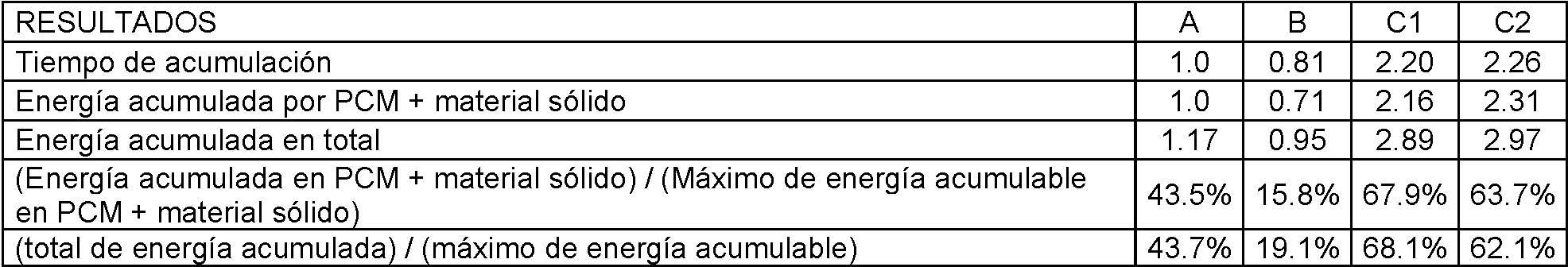
La tabla anterior muestra resultados de:The table above shows results for:
• Tiempo de acumulación: E s el tiempo de funcionamiento del dispositivo, antes de llegar a la temperatura de consigna. Se ha expresado en forma relativa al caso A; es decir, el caso B tiene un tiempo de funcionamiento del 81% con respecto al tiempo del caso A.• Accumulation time: It is the operating time of the device, before reaching the set temperature. It has been expressed relative to case A; that is, case B has an operating time of 81% with respect to the time of case A.
Se ha puesto un único tiempo de funcionamiento, ya que el tiempo resultante para los procesos de carga y de descarga son casi los mismos, dadas las suposiciones realizadas.A single operating time has been set, since the resulting time for the loading and unloading processes are almost the same, given the assumptions made.
Un mayor tiempo de acumulación es un buen indicador de una mayor cantidad de energía acumulada (o entregada), dado que la temperatura de salida (en ambos procesos) no cambia mucho para los diferentes casos, debido a que el rango de temperaturas admisibles es relativamente estrecho.A longer accumulation time is a good indicator of a greater amount of accumulated (or delivered) energy, since the outlet temperature (in both processes) does not change much for the different cases, because the range of admissible temperatures is relatively close.
• Energía acumulada en PCM material sólido: E s la cantidad de energía que se ha acumulado en el proceso de carga (o entregado en el de descarga) en el PCM y en el material sólido. Al igual que con el tiempo de funcionamiento, este valor se ha expresado en forma relativa al valor del caso A.• Energy accumulated in solid material PCM: It is the amount of energy that has accumulated in the charging process (or delivered in the discharge process) in the PCM and in the solid material. As with the operating time, this value has been expressed relative to the value of case A.
• Energía acumulada en total: E s el total de energía acumulada (o entregada) por el sistema de acumulación. Incluye la energía acumulada en PCM material sólido y la energía acumulada en el fluido calor portador que permanece en el tanque luego de cada proceso. Este valor se expresa en función al calor acumulado en PCM material sólido del caso A. E s decir, la energía acumulada en total, en el caso A, es un 17% mayor a la energía acumulada en PCM material sólido del mismo caso; mientras que en el caso C1, el total acumulado equivale a 2.89 veces lo acumulado en el caso A en PCM relleno.• Total accumulated energy: This is the total energy accumulated (or delivered) by the accumulation system. It includes the energy accumulated in solid material PCM and the energy accumulated in the heat carrier fluid that remains in the tank after each process. This value is expressed as a function of the heat accumulated in solid material PCM of case A. That is to say, the total accumulated energy, in case A, is 17% greater than the energy accumulated in solid PCM material from the same case; while in case C1, the accumulated total is equal to 2.89 times what is accumulated in case A in filled PCM.
• (Energía acumulada en PCM material sólido) / (Máxima energía acumulable en PCM material sólido): Equivale a la relación entre los valores de energía acumulada en PCM material sólido y la energía que podría ser acumulada si se usara la capacidad total (sensible y latente) del material de relleno. O sea, este valor intenta expresar una medida de eficiencia de utilización del total del material contenido en el tanque (PCM material sensible).• (Energy accumulated in solid material PCM) / (Maximum accumulated energy in solid material PCM): Equivalent to the relationship between the accumulated energy values in solid material PCM and the energy that could be accumulated if the total capacity (sensible and latent) of the filler material. That is, this value tries to express a measure of efficiency of use of the total material contained in the tank (PCM sensitive material).
• (Energía acumulada en total) / (Máximo de energía acumulable): Equivale a la relación entre los valores de energía acumulada en total y la energía que podría ser acumulada si se usara la capacidad total de todos los materiales dentro del tanque. La diferencia con el valor anterior es que en este caso se incluye la acumulación de energía en el fluido calor portador confinado en el tanque. Este valor intenta expresar una medida de eficiencia de utilización de todo el material contenido en el tanque.• (Total accumulated energy) / (Maximum accumulated energy): Equivalent to the ratio between the total accumulated energy values and the energy that could be accumulated if the total capacity of all the materials inside the tank were used. The difference with the previous value is that in this case the accumulation of energy in the heat carrier fluid confined in the tank is included. This value tries to express a measure of efficiency of use of all the material contained in the tank.
Se puede observar que los peores resultados han sido obtenidos con el caso B, es decir, con el tanque de acumulación relleno totalmente de un PCM cuya temperatura de fusión no está dentro del rango admisible de ninguno de los procesos (carga o descarga). El caso A, es el siguiente en cuanto a peores resultados, mientras que los casos C1 y C2, que corresponden a tanques híbridos, son los que mejores resultados muestran. El caso que utiliza cuatro PCM muestra resultados ligeramente mejores que el que incluye solo dos; sin embargo, la eficiencia en la utilización del material acumulador es menor en el primero.It can be seen that the worst results have been obtained with case B, that is, with the accumulation tank completely filled with a PCM whose melting temperature is not within the admissible range of any of the processes (loading or unloading). Case A is the next in terms of worst results, while cases C1 and C2, which correspond to hybrid tanks, show the best results. The case that uses four PCMs shows slightly better results than the one that includes only two; however, the efficiency in the use of the accumulator material is lower in the former.
E s necesario indicar que las composiciones consideradas en los casos C1 y C2 no necesariamente son las óptimas (fijando los materiales que se utilizan y variando la altura de tanque que ocupa cada uno) en cuanto a resultados de energía acumulada; y que dichos resultados varían sensiblemente con la modificación de las cantidades que se incluyen, siendo necesario un cuidadoso estudio para obtener dicho óptimo (teniendo en cuenta a su vez, criterios de eficiencia de utilización y costes). Los casos C1 y C2 aquí presentados han sido elegidos de entre los mejores, obtenidos luego de haber realizado varias pruebas, y sin más intención que presentar de forma ilustrativa las posibilidades de la invención.It is necessary to indicate that the compositions considered in the cases C1 and C2 are not necessarily optimal (fixing the materials used and varying the height of the tank that each one occupies) in terms of accumulated energy results; and that said results vary significantly with the modification of the amounts that are included, a careful study being necessary to obtain said optimum (taking into account, in turn, criteria of efficiency of use and costs). The cases C1 and C2 presented here have been chosen from among the best, obtained after having carried out several tests, and with no other intention than to illustrate the possibilities of the invention.
Cada una de las realizaciones preferidas del sistema de almacenamiento de energía térmica descrita en esta sección y a lo largo de este documento, se pueden acoplar a un sistema que genere calor (e.g., calor residual de un proceso de fabricación), lo almacena durante un periodo de tiempo (tiempo durante el cual el calor residual se produce) y posteriormente es recuperado y entregado al mismo sistema o a un segundo sistema que demanda o consume calor para realizar un proceso a lo largo de un período de tiempo que no corresponde (o corresponde parcialmente) al mismo tiempo de almacenamiento. Este tipo realizaciones preferidas no necesariamente han de operar a altas temperaturas, como en el caso del generador de electricidad que emplea como fuente de energía la radiación solar que se ha venido empleando como ejemplo.Each of the preferred embodiments of the thermal energy storage system described in this section and throughout this document can be coupled to a system that generates heat (eg, waste heat from a manufacturing process), stores it for a period of time. of time (time during which the residual heat is produced) and later it is recovered and delivered to the same system or to a second system that demands or consumes heat to carry out a process over a period of time that does not correspond (or partially corresponds ) at the same time of storage. This type of preferred embodiments do not necessarily have to operate at high temperatures, as in the case of the electricity generator that uses solar radiation as an energy source that has been used as an example.
Descrita suficientemente la naturaleza de la presente invención, as í como la forma de ponerla en práctica, no se considera necesario hacer más extensa la descripción para que cualquier experto en la materia comprenda los alcances y ventajas de la invención. Se hace constar que, dentro de su esencialidad, podrá ser llevada a cabo en otras formas de realización, dentro de las reivindicaciones, que difieran en detalle de la indicada a título de ejemplo, y a las cuales alcanzará igualmente la protección que se recaba siempre que no se altere, cambie o modifique su principio fundamental. Having sufficiently described the nature of the present invention, as well as the way of putting it into practice, it is not considered necessary to make the description more extensive so that any expert in the field understands the scope and advantages of the invention. It is stated that, within its essentiality, it may be carried out in other forms of embodiment, within the claims, which differ in detail from that indicated by way of example, and to which the protection that is sought will also be achieved provided that its fundamental principle is not altered, changed or modified.
Claims (12)
Applications Claiming Priority (2)
| Application Number | Priority Date | Filing Date | Title |
|---|---|---|---|
| ES201232038A ES2480765B1 (en) | 2012-12-27 | 2012-12-27 | Thermal energy storage system combining solid heat sensitive material and phase change material |
| PCT/ES2013/070889 WO2014102418A1 (en) | 2012-12-27 | 2013-12-18 | Thermal energy storage system combining solid sensible heat material and phase change material |
Publications (1)
| Publication Number | Publication Date |
|---|---|
| ES2828525T3 true ES2828525T3 (en) | 2021-05-26 |
Family
ID=51019924
Family Applications (2)
| Application Number | Title | Priority Date | Filing Date |
|---|---|---|---|
| ES201232038A Active ES2480765B1 (en) | 2012-12-27 | 2012-12-27 | Thermal energy storage system combining solid heat sensitive material and phase change material |
| ES13868352T Active ES2828525T3 (en) | 2012-12-27 | 2013-12-18 | Thermal energy storage system combining heat sensitive solid material and phase change material |
Family Applications Before (1)
| Application Number | Title | Priority Date | Filing Date |
|---|---|---|---|
| ES201232038A Active ES2480765B1 (en) | 2012-12-27 | 2012-12-27 | Thermal energy storage system combining solid heat sensitive material and phase change material |
Country Status (5)
| Country | Link |
|---|---|
| US (1) | US9841243B2 (en) |
| EP (1) | EP2942591B1 (en) |
| CN (1) | CN105008840B (en) |
| ES (2) | ES2480765B1 (en) |
| WO (1) | WO2014102418A1 (en) |
Families Citing this family (44)
| Publication number | Priority date | Publication date | Assignee | Title |
|---|---|---|---|---|
| US10094219B2 (en) | 2010-03-04 | 2018-10-09 | X Development Llc | Adiabatic salt energy storage |
| WO2014052927A1 (en) | 2012-09-27 | 2014-04-03 | Gigawatt Day Storage Systems, Inc. | Systems and methods for energy storage and retrieval |
| SE536722C2 (en) * | 2012-11-01 | 2014-06-17 | Skanska Sverige Ab | energy Storage |
| ES2480765B1 (en) | 2012-12-27 | 2015-05-08 | Universitat Politècnica De Catalunya | Thermal energy storage system combining solid heat sensitive material and phase change material |
| DE102014208454A1 (en) * | 2014-05-06 | 2015-11-12 | Siemens Aktiengesellschaft | heat storage |
| NO339952B1 (en) * | 2014-12-19 | 2017-02-20 | Energynest As | Thermal energy storage and heat exchanger |
| JP6604721B2 (en) * | 2014-12-26 | 2019-11-13 | 永大産業株式会社 | Thermal storage material impregnated with latent heat storage material with excellent heat resistance |
| DK3245467T3 (en) * | 2015-03-20 | 2019-05-13 | Siemens Gamesa Renewable Energy As | Heat energy storage with increased capacity |
| EP3121547A1 (en) * | 2015-07-22 | 2017-01-25 | ETH Zurich | System and method for storing and releasing heat |
| FR3040211A1 (en) * | 2015-08-20 | 2017-02-24 | Hutchinson | JOINT ASSEMBLY AND PANEL FOR THERMAL INSULATION |
| FR3044750B1 (en) * | 2015-12-04 | 2017-12-15 | Ifp Energies Now | SYSTEM AND METHOD FOR COMPRESSED GAS ENERGY STORAGE AND RESTITUTION |
| CN106766276B (en) * | 2016-12-09 | 2020-03-10 | 湖南哲能赫新能源有限责任公司 | Efficient heat storage water tank capable of utilizing phase change materials in layered mode and design method thereof |
| KR102506851B1 (en) | 2016-12-14 | 2023-03-08 | 현대자동차주식회사 | Heat exchange device for cooling water of fuel cell and fuel cell system comprising the same |
| KR102518536B1 (en) * | 2016-12-15 | 2023-04-07 | 현대자동차주식회사 | Heat exchange device for cooling water of fuel cell and fuel cell system comprising the same |
| US11053847B2 (en) | 2016-12-28 | 2021-07-06 | Malta Inc. | Baffled thermoclines in thermodynamic cycle systems |
| US10233833B2 (en) | 2016-12-28 | 2019-03-19 | Malta Inc. | Pump control of closed cycle power generation system |
| US10233787B2 (en) | 2016-12-28 | 2019-03-19 | Malta Inc. | Storage of excess heat in cold side of heat engine |
| US10458284B2 (en) | 2016-12-28 | 2019-10-29 | Malta Inc. | Variable pressure inventory control of closed cycle system with a high pressure tank and an intermediate pressure tank |
| US10221775B2 (en) | 2016-12-29 | 2019-03-05 | Malta Inc. | Use of external air for closed cycle inventory control |
| US10801404B2 (en) | 2016-12-30 | 2020-10-13 | Malta Inc. | Variable pressure turbine |
| US10436109B2 (en) | 2016-12-31 | 2019-10-08 | Malta Inc. | Modular thermal storage |
| US11015877B2 (en) * | 2017-02-07 | 2021-05-25 | Battelle Energy Alliance, Llc | Energy storage systems including thermal storage tanks |
| CN110573822B (en) * | 2017-03-02 | 2022-04-12 | 海利亚克有限公司 | Heat transfer based on heat of vaporization for pipeless thermal storage |
| KR102650755B1 (en) * | 2017-03-17 | 2024-03-22 | 미쯔비시 케미컬 주식회사 | Partition member and assembled battery |
| AU2018237999A1 (en) | 2017-03-23 | 2019-10-24 | Yeda Research And Development Co. Ltd. | Solar system for energy production |
| WO2018210389A1 (en) * | 2017-05-15 | 2018-11-22 | Seas-Nve Holding A/S | A heat storage unit |
| CN107227807A (en) * | 2017-06-13 | 2017-10-03 | 华南理工大学 | A kind of phase-change accumulation energy building heat preservation structure |
| CH714495A2 (en) * | 2017-12-21 | 2019-06-28 | Bms Energietechnik Ag | Apparatus for providing heating and / or domestic hot water. |
| CN110273779A (en) * | 2018-03-13 | 2019-09-24 | 浙江大学 | Regenerator and stirling cycle system based on phase-change material |
| GB2575680B (en) * | 2018-07-20 | 2022-07-13 | Bae Systems Plc | Thermal management system |
| GB2575679B (en) | 2018-07-20 | 2022-06-15 | Bae Systems Plc | Thermal Management System |
| DE102018213018A1 (en) | 2018-08-03 | 2020-02-06 | Karlsruher Institut für Technologie | Device and method for thermal-electrochemical energy storage and energy supply |
| FR3099821B1 (en) * | 2019-08-08 | 2022-04-29 | Eco Tech Ceram | Improved thermal storage device |
| CN116566064A (en) | 2019-11-16 | 2023-08-08 | 马耳他股份有限公司 | Dual power system pumping thermoelectric storage with ambient heat exchanger bypass |
| CN110763065B (en) * | 2019-11-29 | 2024-04-19 | 浙江大学 | Hybrid heat storage and release integrated tank |
| SE545571C2 (en) | 2020-06-11 | 2023-10-24 | Vattenfall Ab | A method for storing thermal energy, a thermal storage system and a use of such a thermal storage system |
| US11454167B1 (en) | 2020-08-12 | 2022-09-27 | Malta Inc. | Pumped heat energy storage system with hot-side thermal integration |
| US11396826B2 (en) | 2020-08-12 | 2022-07-26 | Malta Inc. | Pumped heat energy storage system with electric heating integration |
| US11486305B2 (en) | 2020-08-12 | 2022-11-01 | Malta Inc. | Pumped heat energy storage system with load following |
| US11286804B2 (en) | 2020-08-12 | 2022-03-29 | Malta Inc. | Pumped heat energy storage system with charge cycle thermal integration |
| US11480067B2 (en) | 2020-08-12 | 2022-10-25 | Malta Inc. | Pumped heat energy storage system with generation cycle thermal integration |
| EP4067802A1 (en) * | 2021-03-30 | 2022-10-05 | Siemens Gamesa Renewable Energy GmbH & Co. KG | Thermal energy storage device |
| DK181030B1 (en) | 2021-03-31 | 2022-10-07 | Stiesdal Storage As | Thermal energy storage system with phase change material and method of its operation |
| CN114777542B (en) * | 2021-11-03 | 2023-08-22 | 山东大学 | Manifold shell-and-tube heat exchanger |
Family Cites Families (24)
| Publication number | Priority date | Publication date | Assignee | Title |
|---|---|---|---|---|
| US4164253A (en) * | 1975-05-07 | 1979-08-14 | Skala Stephen F | Method for reducing thermal degradation of a heat exchange fluid |
| JPS5856080B2 (en) * | 1979-07-07 | 1983-12-13 | 工業技術院長 | heat storage device |
| JPS5924356B2 (en) * | 1979-07-07 | 1984-06-08 | 工業技術院長 | heat storage device |
| US4512388A (en) | 1981-06-19 | 1985-04-23 | Institute Of Gas Technology | High-temperature direct-contact thermal energy storage using phase-change media |
| US4523629A (en) | 1982-09-30 | 1985-06-18 | The United States Of America As Represented By The United States Department Of Energy | Method and apparatus for operating an improved thermocline storage unit |
| JPS61228293A (en) * | 1985-04-02 | 1986-10-11 | Atsuo Yoshida | Underground storage of heat by hygroscopic substance |
| JP2000292085A (en) * | 1999-04-06 | 2000-10-20 | Chubu Electric Power Co Inc | Heat storage body, heat storage device and manufacture thereof |
| PT2141432E (en) | 2008-07-01 | 2011-05-05 | Sener Ing & Sist | Dual thermal energy storage tank |
| US20100230075A1 (en) | 2009-03-11 | 2010-09-16 | Terrafore, Inc. | Thermal Storage System |
| US9657966B2 (en) | 2009-06-01 | 2017-05-23 | Solarreserve | Single bi-temperature thermal storage tank for application in solar thermal plant |
| DE102009034655A1 (en) * | 2009-07-24 | 2011-01-27 | J. Eberspächer GmbH & Co. KG | Latent heat storage |
| CN201583173U (en) * | 2009-11-02 | 2010-09-15 | 上海汽车资产经营有限公司 | Combined type heat storage device |
| GB0919934D0 (en) * | 2009-11-16 | 2009-12-30 | Sunamp Ltd | Energy storage systems |
| JP2011144961A (en) * | 2010-01-12 | 2011-07-28 | Kobe Steel Ltd | Heat storage heating device |
| CN101738120B (en) * | 2010-02-03 | 2012-06-27 | 中国科学院电工研究所 | Sensible heat-latent heat compound thermal storage device |
| US20110259544A1 (en) | 2010-04-21 | 2011-10-27 | Lehigh University | Encapsulated phase change apparatus for thermal energy storage |
| US20120018116A1 (en) | 2010-07-21 | 2012-01-26 | Terrafore, Inc | Thermal energy storage system comprising encapsulated phase change material |
| US20120055661A1 (en) | 2010-09-03 | 2012-03-08 | Peter Feher | High temperature thermal energy storage system |
| US20120104003A1 (en) | 2010-10-12 | 2012-05-03 | Brian Eric Lee | Horizontal Extraction and Return Extensions in liquid storage tanks |
| US8554377B2 (en) | 2010-11-12 | 2013-10-08 | Terrafore, Inc. | Thermal energy storage system comprising optimal thermocline management |
| WO2012138978A2 (en) * | 2011-04-06 | 2012-10-11 | Dow Global Technologies Llc | Dome shaped capsules of thermal energy storage material for improved heat storage |
| CN202221162U (en) * | 2011-08-11 | 2012-05-16 | 袁艳平 | Hot water/electric energy one-piece phase-change heat storage water tank |
| US9548504B2 (en) * | 2012-01-24 | 2017-01-17 | University Of Connecticut | Utilizing phase change material, heat pipes, and fuel cells for aircraft applications |
| ES2480765B1 (en) | 2012-12-27 | 2015-05-08 | Universitat Politècnica De Catalunya | Thermal energy storage system combining solid heat sensitive material and phase change material |
-
2012
- 2012-12-27 ES ES201232038A patent/ES2480765B1/en active Active
-
2013
- 2013-12-18 EP EP13868352.9A patent/EP2942591B1/en active Active
- 2013-12-18 US US14/655,722 patent/US9841243B2/en active Active
- 2013-12-18 ES ES13868352T patent/ES2828525T3/en active Active
- 2013-12-18 CN CN201380073528.5A patent/CN105008840B/en active Active
- 2013-12-18 WO PCT/ES2013/070889 patent/WO2014102418A1/en active Application Filing
Also Published As
| Publication number | Publication date |
|---|---|
| US20160201995A1 (en) | 2016-07-14 |
| WO2014102418A1 (en) | 2014-07-03 |
| US9841243B2 (en) | 2017-12-12 |
| EP2942591A1 (en) | 2015-11-11 |
| ES2480765B1 (en) | 2015-05-08 |
| CN105008840B (en) | 2019-03-01 |
| EP2942591A4 (en) | 2016-11-02 |
| ES2480765A1 (en) | 2014-07-28 |
| EP2942591B1 (en) | 2020-08-05 |
| CN105008840A (en) | 2015-10-28 |
Similar Documents
| Publication | Publication Date | Title |
|---|---|---|
| ES2828525T3 (en) | Thermal energy storage system combining heat sensitive solid material and phase change material | |
| Douvi et al. | Phase change materials in solar domestic hot water systems: A review | |
| Ma et al. | Investigation on the performance of a high-temperature packed bed latent heat thermal energy storage system using Al-Si alloy | |
| Aramesh et al. | Metal foam-phase change material composites for thermal energy storage: a review of performance parameters | |
| Li et al. | Investigation on the thermal performance of a high temperature packed bed thermal energy storage system containing carbonate salt based composite phase change materials | |
| ES2784773T3 (en) | High temperature heat accumulator for solar thermal power plants | |
| Kuravi et al. | Thermal energy storage technologies and systems for concentrating solar power plants | |
| Fazilati et al. | Phase change material for enhancing solar water heater, an experimental approach | |
| Elfeky et al. | Thermal and economic evaluation of phase change material volume fraction for thermocline tank used in concentrating solar power plants | |
| ES2532004T3 (en) | Hydrogen storage tank with metal hydrides | |
| WO2015189450A1 (en) | Thermal storage system and method for charging and discharging same | |
| Koide et al. | Performance analysis of packed bed latent heat storage system for high-temperature thermal energy storage using pellets composed of micro-encapsulated phase change material | |
| ES2475715T3 (en) | Hydrogen storage tank in metal hydrides | |
| Duan et al. | Thermal performance of structured packed bed with encapsulated phase change materials | |
| Khan et al. | Progress in research and development of phase change materials for thermal energy storage in concentrated solar power | |
| CN102967162A (en) | Heat storage pipe of internally provided with phase change material | |
| JP2014513260A (en) | Particularly suitable for heat storage equipment | |
| CN106959032A (en) | A kind of high-temperature molten salt phase transformation stores heat-releasing device | |
| Dhaou et al. | Experimental assessment of a solar water tank integrated with nano-enhanced PCM and a stirrer | |
| Xie et al. | Thermocline packed bed thermal energy storage system: a review | |
| Mellouli et al. | Parametric assessment of a hybrid heat storage unit based on paired metal hydrides and phase change materials | |
| JP3752536B2 (en) | Heat storage tank, heat utilization device and heat utilization method thereof | |
| CN103557733B (en) | Suspended sensible heat-latent heat type heat accumulation device for solar heating | |
| CN105758241A (en) | Electrically-heated energy-storage heat exchanger and heat storing and releasing method thereof | |
| US20160137388A1 (en) | Molten salts insulated storage tank |