EP4582702A1 - Hydraulikzylinder - Google Patents
Hydraulikzylinder Download PDFInfo
- Publication number
- EP4582702A1 EP4582702A1 EP22957459.5A EP22957459A EP4582702A1 EP 4582702 A1 EP4582702 A1 EP 4582702A1 EP 22957459 A EP22957459 A EP 22957459A EP 4582702 A1 EP4582702 A1 EP 4582702A1
- Authority
- EP
- European Patent Office
- Prior art keywords
- piston
- holder
- cylinder
- chamber
- hole
- Prior art date
- Legal status (The legal status is an assumption and is not a legal conclusion. Google has not performed a legal analysis and makes no representation as to the accuracy of the status listed.)
- Pending
Links
Images





Classifications
-
- F—MECHANICAL ENGINEERING; LIGHTING; HEATING; WEAPONS; BLASTING
- F15—FLUID-PRESSURE ACTUATORS; HYDRAULICS OR PNEUMATICS IN GENERAL
- F15B—SYSTEMS ACTING BY MEANS OF FLUIDS IN GENERAL; FLUID-PRESSURE ACTUATORS, e.g. SERVOMOTORS; DETAILS OF FLUID-PRESSURE SYSTEMS, NOT OTHERWISE PROVIDED FOR
- F15B15/00—Fluid-actuated devices for displacing a member from one position to another; Gearing associated therewith
- F15B15/08—Characterised by the construction of the motor unit
- F15B15/14—Characterised by the construction of the motor unit of the straight-cylinder type
- F15B15/1423—Component parts; Constructional details
- F15B15/1428—Cylinders
-
- F—MECHANICAL ENGINEERING; LIGHTING; HEATING; WEAPONS; BLASTING
- F15—FLUID-PRESSURE ACTUATORS; HYDRAULICS OR PNEUMATICS IN GENERAL
- F15B—SYSTEMS ACTING BY MEANS OF FLUIDS IN GENERAL; FLUID-PRESSURE ACTUATORS, e.g. SERVOMOTORS; DETAILS OF FLUID-PRESSURE SYSTEMS, NOT OTHERWISE PROVIDED FOR
- F15B15/00—Fluid-actuated devices for displacing a member from one position to another; Gearing associated therewith
- F15B15/08—Characterised by the construction of the motor unit
- F15B15/14—Characterised by the construction of the motor unit of the straight-cylinder type
- F15B15/149—Fluid interconnections, e.g. fluid connectors, passages
-
- F—MECHANICAL ENGINEERING; LIGHTING; HEATING; WEAPONS; BLASTING
- F15—FLUID-PRESSURE ACTUATORS; HYDRAULICS OR PNEUMATICS IN GENERAL
- F15B—SYSTEMS ACTING BY MEANS OF FLUIDS IN GENERAL; FLUID-PRESSURE ACTUATORS, e.g. SERVOMOTORS; DETAILS OF FLUID-PRESSURE SYSTEMS, NOT OTHERWISE PROVIDED FOR
- F15B15/00—Fluid-actuated devices for displacing a member from one position to another; Gearing associated therewith
- F15B15/08—Characterised by the construction of the motor unit
- F15B15/14—Characterised by the construction of the motor unit of the straight-cylinder type
-
- F—MECHANICAL ENGINEERING; LIGHTING; HEATING; WEAPONS; BLASTING
- F15—FLUID-PRESSURE ACTUATORS; HYDRAULICS OR PNEUMATICS IN GENERAL
- F15B—SYSTEMS ACTING BY MEANS OF FLUIDS IN GENERAL; FLUID-PRESSURE ACTUATORS, e.g. SERVOMOTORS; DETAILS OF FLUID-PRESSURE SYSTEMS, NOT OTHERWISE PROVIDED FOR
- F15B15/00—Fluid-actuated devices for displacing a member from one position to another; Gearing associated therewith
- F15B15/08—Characterised by the construction of the motor unit
- F15B15/14—Characterised by the construction of the motor unit of the straight-cylinder type
- F15B15/1423—Component parts; Constructional details
- F15B15/1433—End caps
-
- F—MECHANICAL ENGINEERING; LIGHTING; HEATING; WEAPONS; BLASTING
- F15—FLUID-PRESSURE ACTUATORS; HYDRAULICS OR PNEUMATICS IN GENERAL
- F15B—SYSTEMS ACTING BY MEANS OF FLUIDS IN GENERAL; FLUID-PRESSURE ACTUATORS, e.g. SERVOMOTORS; DETAILS OF FLUID-PRESSURE SYSTEMS, NOT OTHERWISE PROVIDED FOR
- F15B15/00—Fluid-actuated devices for displacing a member from one position to another; Gearing associated therewith
- F15B15/08—Characterised by the construction of the motor unit
- F15B15/14—Characterised by the construction of the motor unit of the straight-cylinder type
- F15B15/1423—Component parts; Constructional details
- F15B15/1447—Pistons; Piston to piston rod assemblies
-
- F—MECHANICAL ENGINEERING; LIGHTING; HEATING; WEAPONS; BLASTING
- F15—FLUID-PRESSURE ACTUATORS; HYDRAULICS OR PNEUMATICS IN GENERAL
- F15B—SYSTEMS ACTING BY MEANS OF FLUIDS IN GENERAL; FLUID-PRESSURE ACTUATORS, e.g. SERVOMOTORS; DETAILS OF FLUID-PRESSURE SYSTEMS, NOT OTHERWISE PROVIDED FOR
- F15B15/00—Fluid-actuated devices for displacing a member from one position to another; Gearing associated therewith
- F15B15/08—Characterised by the construction of the motor unit
- F15B15/14—Characterised by the construction of the motor unit of the straight-cylinder type
- F15B15/1423—Component parts; Constructional details
- F15B15/1457—Piston rods
-
- F—MECHANICAL ENGINEERING; LIGHTING; HEATING; WEAPONS; BLASTING
- F15—FLUID-PRESSURE ACTUATORS; HYDRAULICS OR PNEUMATICS IN GENERAL
- F15B—SYSTEMS ACTING BY MEANS OF FLUIDS IN GENERAL; FLUID-PRESSURE ACTUATORS, e.g. SERVOMOTORS; DETAILS OF FLUID-PRESSURE SYSTEMS, NOT OTHERWISE PROVIDED FOR
- F15B15/00—Fluid-actuated devices for displacing a member from one position to another; Gearing associated therewith
- F15B15/08—Characterised by the construction of the motor unit
- F15B15/14—Characterised by the construction of the motor unit of the straight-cylinder type
- F15B15/1423—Component parts; Constructional details
- F15B15/1457—Piston rods
- F15B15/1461—Piston rod sealings
-
- F—MECHANICAL ENGINEERING; LIGHTING; HEATING; WEAPONS; BLASTING
- F15—FLUID-PRESSURE ACTUATORS; HYDRAULICS OR PNEUMATICS IN GENERAL
- F15B—SYSTEMS ACTING BY MEANS OF FLUIDS IN GENERAL; FLUID-PRESSURE ACTUATORS, e.g. SERVOMOTORS; DETAILS OF FLUID-PRESSURE SYSTEMS, NOT OTHERWISE PROVIDED FOR
- F15B15/00—Fluid-actuated devices for displacing a member from one position to another; Gearing associated therewith
- F15B15/20—Other details, e.g. assembly with regulating devices
- F15B15/22—Other details, e.g. assembly with regulating devices for accelerating or decelerating the stroke
- F15B15/226—Other details, e.g. assembly with regulating devices for accelerating or decelerating the stroke having elastic elements, e.g. springs, rubber pads
-
- F—MECHANICAL ENGINEERING; LIGHTING; HEATING; WEAPONS; BLASTING
- F15—FLUID-PRESSURE ACTUATORS; HYDRAULICS OR PNEUMATICS IN GENERAL
- F15B—SYSTEMS ACTING BY MEANS OF FLUIDS IN GENERAL; FLUID-PRESSURE ACTUATORS, e.g. SERVOMOTORS; DETAILS OF FLUID-PRESSURE SYSTEMS, NOT OTHERWISE PROVIDED FOR
- F15B15/00—Fluid-actuated devices for displacing a member from one position to another; Gearing associated therewith
- F15B15/20—Other details, e.g. assembly with regulating devices
- F15B15/28—Means for indicating the position, e.g. end of stroke
- F15B15/2807—Position switches, i.e. means for sensing of discrete positions only, e.g. limit switches
-
- F—MECHANICAL ENGINEERING; LIGHTING; HEATING; WEAPONS; BLASTING
- F15—FLUID-PRESSURE ACTUATORS; HYDRAULICS OR PNEUMATICS IN GENERAL
- F15B—SYSTEMS ACTING BY MEANS OF FLUIDS IN GENERAL; FLUID-PRESSURE ACTUATORS, e.g. SERVOMOTORS; DETAILS OF FLUID-PRESSURE SYSTEMS, NOT OTHERWISE PROVIDED FOR
- F15B15/00—Fluid-actuated devices for displacing a member from one position to another; Gearing associated therewith
- F15B15/20—Other details, e.g. assembly with regulating devices
- F15B15/28—Means for indicating the position, e.g. end of stroke
- F15B15/2815—Position sensing, i.e. means for continuous measurement of position, e.g. LVDT
-
- F—MECHANICAL ENGINEERING; LIGHTING; HEATING; WEAPONS; BLASTING
- F15—FLUID-PRESSURE ACTUATORS; HYDRAULICS OR PNEUMATICS IN GENERAL
- F15B—SYSTEMS ACTING BY MEANS OF FLUIDS IN GENERAL; FLUID-PRESSURE ACTUATORS, e.g. SERVOMOTORS; DETAILS OF FLUID-PRESSURE SYSTEMS, NOT OTHERWISE PROVIDED FOR
- F15B15/00—Fluid-actuated devices for displacing a member from one position to another; Gearing associated therewith
- F15B15/20—Other details, e.g. assembly with regulating devices
- F15B15/28—Means for indicating the position, e.g. end of stroke
- F15B15/2892—Means for indicating the position, e.g. end of stroke characterised by the attachment means
-
- F—MECHANICAL ENGINEERING; LIGHTING; HEATING; WEAPONS; BLASTING
- F15—FLUID-PRESSURE ACTUATORS; HYDRAULICS OR PNEUMATICS IN GENERAL
- F15B—SYSTEMS ACTING BY MEANS OF FLUIDS IN GENERAL; FLUID-PRESSURE ACTUATORS, e.g. SERVOMOTORS; DETAILS OF FLUID-PRESSURE SYSTEMS, NOT OTHERWISE PROVIDED FOR
- F15B21/00—Common features of fluid actuator systems; Fluid-pressure actuator systems or details thereof, not covered by any other group of this subclass
- F15B21/003—Systems with different interchangeable components, e.g. using preassembled kits
-
- F—MECHANICAL ENGINEERING; LIGHTING; HEATING; WEAPONS; BLASTING
- F15—FLUID-PRESSURE ACTUATORS; HYDRAULICS OR PNEUMATICS IN GENERAL
- F15B—SYSTEMS ACTING BY MEANS OF FLUIDS IN GENERAL; FLUID-PRESSURE ACTUATORS, e.g. SERVOMOTORS; DETAILS OF FLUID-PRESSURE SYSTEMS, NOT OTHERWISE PROVIDED FOR
- F15B2211/00—Circuits for servomotor systems
- F15B2211/70—Output members, e.g. hydraulic motors or cylinders or control therefor
- F15B2211/705—Output members, e.g. hydraulic motors or cylinders or control therefor characterised by the type of output members or actuators
- F15B2211/7051—Linear output members
-
- F—MECHANICAL ENGINEERING; LIGHTING; HEATING; WEAPONS; BLASTING
- F15—FLUID-PRESSURE ACTUATORS; HYDRAULICS OR PNEUMATICS IN GENERAL
- F15B—SYSTEMS ACTING BY MEANS OF FLUIDS IN GENERAL; FLUID-PRESSURE ACTUATORS, e.g. SERVOMOTORS; DETAILS OF FLUID-PRESSURE SYSTEMS, NOT OTHERWISE PROVIDED FOR
- F15B2211/00—Circuits for servomotor systems
- F15B2211/80—Other types of control related to particular problems or conditions
- F15B2211/885—Control specific to the type of fluid, e.g. specific to magnetorheological fluid
- F15B2211/8855—Compressible fluids, e.g. specific to pneumatics
Definitions
- the present invention relates to a fluid pressure cylinder (hydraulic cylinder) which operates based on supply and discharge of a pressure fluid.
- an air cylinder includes a cylinder tube in which a piston chamber is formed, and a piston accommodated in the piston chamber.
- a supply/discharge tube for supplying and discharging compressed air to and from the piston chamber is connected to the air cylinder.
- a position sensor for detecting the position of the piston is provided in the cylinder tube.
- a seal member (packing) is mounted on a side peripheral wall (outer peripheral portion) of the piston. The seal member seals a gap between a side peripheral wall of the piston and an inner peripheral wall of the piston chamber.
- the fluid pressure cylinder having the above configuration includes the cylinder unit in which the piston, the piston rod, and the like are integrally assembled.
- the cylinder unit is insertably and removably accommodated in the accommodation chamber of the cylinder housing. Therefore, in the case that it comes time for the maintenance work of the cylinder unit, for example, the cylinder unit is replaced with a spare unit. This makes it possible to operate the fluid pressure cylinder again.
- the cylinder unit when the cylinder unit is replaced with a spare unit, it is not particularly necessary to remove the cylinder housing from facilities or equipment. That is, the cylinder unit can be replaced with a spare unit while the cylinder housing is fixed to the facilities or the equipment. Further, it is not particularly necessary to remove the position sensor and the wiring connected to the position sensor from the cylinder housing.
- the maintenance work of the fluid pressure cylinder can be completed.
- the maintenance work is only to replace the cylinder unit with a spare unit.
- the number of maintenance work steps is reduced.
- the maintenance work is simplified. That is, the maintenance work can be performed on the fluid pressure cylinder easily and in a short time. Therefore, the operation down-time of the facilities or the equipment is shortened.
- the mounting position of the position sensor with respect to the cylinder housing remains unchanged before and after the cylinder unit is removed from the cylinder housing. Therefore, by the cylinder unit being inserted into the cylinder housing and attached thereto, the piston is positioned at a predetermined specified position and is aligned with the position sensor. That is, the piston and the position sensor are aligned with each other. Thus, the piston and the position sensor can be easily aligned with each other even under a situation where the operator cannot visually recognize the piston.
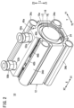
- the X direction shown in the drawings is the axial direction of an air cylinder, a cylinder housing, or a sleeve.
- the X1 direction and the X2 direction along the X direction are opposite to each other.
- the Y direction shown in the drawings is a horizontal direction orthogonal to the X direction.
- the Y1 direction and the Y2 direction along the Y direction are opposite to each other.
- the Z direction shown in the drawings is a vertical direction orthogonal to the X direction and the Y direction.
- the Z1 direction and the Z2 direction along the Z direction are opposite to each other.
- a first side groove 19 is formed in a side peripheral wall of the disk portion 17 (see FIG. 4 ).
- An annular outer seal member 20 is received in the first side groove 19.
- the outer seal member 20 seals a gap between the side peripheral wall of the disk portion 17 and an inner peripheral wall of the cylinder housing 12 in an airtight manner.
- a second side groove 22 is formed in the inner peripheral wall of the cylinder housing 12 in the vicinity of the first opening 15a.
- a snap ring 24, through which the cylinder portion 18 passes, is received in the second side groove 22. The snap ring 24 prevents the cover member 16 from coming off from the cylinder housing 12. In this way, the cover member 16 is positioned and fixed to the cylinder housing 12.
- a first protruding portion 34a and a second protruding portion 34b are provided respectively at a Y1-side end portion and a Y2-side end portion, on the Z1 side, of the cylinder housing 12.
- a third protruding portion 34c and a fourth protruding portion 34d are provided respectively at a Y1-side end portion and a Y2-side end portion, on the Z2 side, of the cylinder housing 12.
- the first to fourth protruding portions 34a to 34d extend along the axial direction (X direction) at the corners of the cylinder housing 12.
- the first to fourth protruding portions 34a to 34d are each provided with an elongated hole 38. For example, a long bolt (not shown) for attaching the air cylinder 10 to a predetermined device or apparatus is inserted into the elongated hole 38.
- the tip of a first supply/discharge tube 56a is connected to the first tube fitting 50a, and the tip of a second supply/discharge tube 56b is connected to the second tube fitting 50b.
- the other ends (not shown) of the first supply/discharge tube 56a and the second supply/discharge tube 56b are connected to a supply/discharge mechanism (not shown). Compressed air flows through the first supply/discharge tube 56a and the second supply/discharge tube 56b.
- the sleeve 66 is a cylindrical body, and the piston 60 slides inside the sleeve 66. That is, the inner space of the sleeve 66 is a piston chamber 68.
- the first holder 58 holds an X-side end portion (one end portion) of the sleeve 66.
- the first holder 58 is positioned between the disk portion 17 of the cover member 16 and the piston 60.
- the disk portion 17 and the first holder 58 are slightly separated from each other. That is, a first annular clearance 63 is formed between the disk portion 17 and the first holder 58.
- the first annular clearance 63 is in communication with the first input/output port 54a.
- a first chamber 86 is formed by the X2-side end surface of the first holder 58, an X1-side end surface 61 of the piston 60 (see FIG. 6 ), and the inner peripheral wall of the sleeve 66.
- the first chamber 86 is a space on one side of the piston chamber 68 partitioned by the piston 60.
- the piston 60 has a fitting hole 87, a packing mounting groove 88, and a magnet mounting groove 89 (see FIG. 6 ).
- the X1-side end portion of the piston rod 62 is fitted into the fitting hole 87 (see FIG. 4 ).
- a packing 90 and a magnet 92 are received in the packing mounting groove 88 and the magnet mounting groove 89, respectively.
- the annular packing 90 seals a gap between the outer peripheral wall of the piston 60 and the inner peripheral wall of the sleeve 66 in an airtight manner.
- the first damper 98 has an inlet/outlet hole 104 as a hollow portion and two inlet/outlet channels 106.
- the two inlet/outlet channels 106 are formed in the second main body portion 100.
- the inlet/outlet hole 104 faces the passage hole 72.
- the inlet/outlet channels 106 each extend from the outer peripheral wall of the second main body portion 100 toward the inner peripheral wall thereof along the diameter direction of the first damper 98.
- the inlet/outlet channels 106 guide the compressed air that has flowed into the inlet/outlet hole 104, to the first chamber 86 that is positioned radially outward of the inlet/outlet hole 104.
- the inlet/outlet channels 106 are grooves formed in an X1-side end surface of the first damper 98.
- the second holder 30 holds the X2-side end portion (the other end portion) of the sleeve 66. As shown in FIG. 4 , the second holder 30 has a second engagement end 110 that protrudes toward the piston 60. The second engagement end 110 is inserted into the other end portion (X2-side end portion) of the sleeve 66.
- the second holder 30 is formed with an engagement recess 112.
- An annular engagement groove 114 recessed radially outward is formed in a radially outer edge portion of a bottom portion of the engagement recess 112.
- a second damper 116 is accommodated in the engagement recess 112.
- the second damper 116 includes a third main body portion 118 and a third flange portion 120.
- the third flange portion 120 is inserted into the engagement groove 114. By this insertion, the second damper 116 is prevented from coming off from the engagement recess 112.
- the X1-side end portion of the third main body portion 118 is slightly protruded from the engagement recess 112. That is, the X1-side end portion of the second damper 116 protrudes toward the piston 60 beyond the X1-side end surface (the end surface facing the piston 60) of the second holder 30.
- the second damper 116 has a supply/discharge hole 124.
- the diameter of the supply/discharge hole 124 is larger than the diameter of the piston rod 62. That is, a second annular clearance 126 is formed between the side peripheral wall of the piston rod 62 and the inner peripheral wall of the supply/discharge hole 124.
- a second chamber 128 is formed by the X2-side end surface of the piston 60, the X1-side end surface of the second holder 30, and the inner peripheral wall of the sleeve 66.
- the second chamber 128 is a space on the other side of the piston chamber 68 partitioned by the piston 60.
- the second holder 30 is formed with an insertion hole 130 through which the piston rod 62 is inserted.
- An inner groove 132 is formed in an inner peripheral wall of the insertion hole 130.
- An annular rod seal 134 is received in the inner groove 132. The rod seal 134 seals a gap between the side peripheral wall of the piston rod 62 and the inner peripheral wall of the insertion hole 130 in an airtight manner.
- a flow passage 136 is formed between the engagement recess 112 and the inner groove 132.
- the flow passage 136 includes a first passage 138 extending in the axial direction (X direction) of the second holder 30 and a second passage 140 extending in the radial direction (Z direction) of the second holder 30.
- the X1-side end of the first passage 138 communicates with the second annular clearance 126.
- the X2-side end of the first passage 138 is closed by the rod seal 134.
- the Z1-side end of the second passage 140 communicates with the first passage 138.
- the Z2-side end of the second passage 140 communicates with the second input/output port 54b. That is, the second annular clearance 126 communicates with the second input/output port 54b via the flow passage 136.
- An annular outer groove 142 is formed in the outer peripheral wall of the second holder 30 at a position shifted in the X2 direction from the second passage 140.
- An annular second unit seal 144 is received in the outer groove 142.
- the second unit seal 144 seals a gap between the outer peripheral wall of the second holder 30 and the inner peripheral wall of the accommodation chamber 31 in an airtight manner. That is, the first unit seal 65 and the second unit seal 144 prevent the compressed air in the piston chamber 68 from leaking into the accommodation chamber 31.
- the second threaded portion 32 is formed at the X2-side end portion of the outer peripheral wall of the second holder 30. As described above, the second threaded portion 32 is screw-engaged with the first threaded portion 26 formed at the X2-side end portion of the cylinder housing 12. Further, an operation portion 146 protruding in the X2 direction is provided on the X2-side end surface of the second holder 30.
- the operation portion 146 is a portion to be clamped by a tool such as a wrench, a spanner, or pliers.
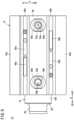
- Two flat surfaces 147 are formed on the outer peripheral wall of the operation portion 146 at positions that are line-symmetrical to each other with respect to the central axis of the second holder 30 (see FIG. 1 ).
- first threaded portion 26 and the second threaded portion 32 are not particularly limited to the above-described positions.
- first threaded portion 26 may be provided on the first opening 15a
- second threaded portion 32 may be provided on the outer peripheral wall of the disk portion 17 of the cover member 16.
- first threaded portion 26 may be provided on the inner peripheral wall of the accommodation chamber 31, and the second threaded portion 32 may be provided on the outer peripheral wall of the sleeve 66.
- the piston rod 62 is inserted into the insertion hole 130 of the second holder 30.
- the piston 60 is mounted on the X1-side end portion of the piston rod 62.
- a coupling hole 148 is formed in the X2-side end portion of the piston rod 62.
- a part of a workpiece (not shown) is inserted into the coupling hole 148. Therefore, when the piston 60 is displaced in the sleeve 66, the piston rod 62 and the workpiece are displaced integrally with the piston 60.
- the workpiece is, for example, a predetermined jig.
- the first engagement end 70 of the first holder 58 is press-fitted into one end portion (X1-side opening) of the sleeve 66.
- the outer peripheral wall of the first engagement end 70 is in close contact with the inner peripheral wall of the one end portion of the sleeve 66 over the entire circumference of the first engagement end 70.
- the second engagement end 110 of the second holder 30 is press-fitted into the other end portion (X2-side opening) of the sleeve 66.
- the outer peripheral wall of the second engagement end 110 is in close contact with the inner peripheral wall of the other end portion of the sleeve 66 over the entire circumference of the second engagement end 110.
- the X1-side opening of the sleeve 66 is closed by the first holder 58, and the X2-side opening of the sleeve 66 is closed by the second holder 30.
- the first holder 58 and the second holder 30 can be manually removed from the sleeve 66.
- the air cylinder 10 according to the present embodiment is basically configured as described above. Next, the operations and advantageous effects of the air cylinder 10 will be described.
- a workpiece is connected to the piston rod 62. More specifically, a part of the workpiece is inserted into the coupling hole 148 of the piston rod 62.
- the air cylinder 10 operates in this state.
- FIG. 4 shows a state in which the compressed air in the first chamber 86 has been discharged, while the compressed air has been supplied to the second chamber 128.
- the piston 60 since the internal pressure of the second chamber 128 is higher than the internal pressure of the first chamber 86, the piston 60 is moved in the X1 direction by receiving the pressure from the compressed air in the second chamber 128, and is positioned at the first position closest to the disk portion 17 of the cover member 16.
- the compressed air is supplied to the first chamber 86, and the compressed air is discharged from the second chamber 128. More specifically, the compressed air is sent from the supply/discharge mechanism to the first supply/discharge tube 56a.
- the guide channels 84 are formed in the holder-side damper 76, and as a result, a path for the compressed air from the first annular clearance 63 to the first chamber 86 is formed. That is, a path for the compressed air for pressing the piston 60 can be provided.
- the piston 60 receives a pressure from the compressed air in the first chamber 86. As a result, the piston 60 slides. That is, the piston 60 moves toward the second holder 30 located at the X2-side end portion. As a result, the air cylinder 10 is brought into a state shown in FIG. 7 . In FIG. 7 , the piston 60 is located at a second position. Thus, the workpiece coupled to the piston rod 62 is moved, for example.
- the second position sensor 42b detects the magnetic force of the magnet 92, and based on this detection, it is detected that the piston 60 has reached the second position.
- the control unit receives the detection signal from the second position sensor 42b and recognizes that the piston 60 has moved to the second position.
- the present embodiment discloses the fluid pressure cylinder wherein the first fixing member is the first threaded portion (26) formed on the inner peripheral wall of the cylinder housing that defines the accommodation chamber, the second fixing member is the second threaded portion (32) formed on the outer peripheral wall of the cylinder unit, and the first threaded portion is screw-engaged with the second threaded portion.
- the cylinder unit is satisfactorily positioned and fixed with respect to the cylinder housing.
- a path for compressed air can be provided reliably.
- the piston rod and the piston are prevented from moving in a state of being eccentric with respect to the piston chamber. Therefore, the workpiece can be moved integrally with the piston rod in a state where the workpiece is in a predetermined posture with respect to the piston rod.
- the piston When the piston moves toward the first holder, the piston may abut against the first holder. In this case, the first holder may be pushed out by the piston and may come into contact with the closing portion. By providing the elastic member on the first holder, the impact when the first holder abuts against the closing portion is damped.
- the present embodiment discloses the fluid pressure cylinder wherein the elastic member includes the end surface (77) that abuts against the closing portion, and the guide channel is a groove formed in the end surface.
- the piston when the piston moves toward the first holder, the piston may come into contact with the first holder.
- the damper provided on the piston reduces the impact occurring when the piston abuts against the first holder.
- the damper is provided with the inlet/outlet channel and the inlet/outlet hole.
- the pressure fluid comes into contact with the piston in the inlet/outlet hole and the first chamber.
- the contact area of the pressure fluid with the piston is larger than in the case where the pressure fluid contacts the piston only at the inlet/outlet hole. Therefore, the piston can be easily moved.
- first threaded portion is positioned at one end portion of the cylinder housing and the second threaded portion is positioned at one end portion of the cylinder unit, it is easy to relatively turn and screw the first threaded portion with respect to the second threaded portion.
- the present embodiment discloses the fluid pressure cylinder wherein the second holder includes: the damper (116) configured to abut against the piston; and the flow passage (136) through which the pressure fluid flows, and the damper includes the supply/discharge hole (124) that communicates with the flow passage.
- the present embodiment discloses the fluid pressure cylinder wherein the cylinder housing includes: the first tube fitting (50a) configured to be connected to the first supply/discharge tube (56a) configured to supply and discharge the pressure fluid; the first attachment hole (52a) to which the first tube fitting is attached; the second tube fitting (50b) configured to be connected to the second supply/discharge tube (56b) configured to supply and discharge the pressure fluid; and the second attachment hole (52b) to which the second tube fitting is attached.
- the present embodiment discloses the fluid pressure cylinder wherein the cylinder housing includes the sensor mounting groove (40a, 40b) in which the position sensor is mounted.
- the position sensor is received in the sensor mounting groove. Therefore, for example, when the maintenance is performed on the fluid pressure cylinder, the position sensor is prevented from interfering with any objects. In other words, the position sensor is protected.
Landscapes
- Engineering & Computer Science (AREA)
- Physics & Mathematics (AREA)
- Fluid Mechanics (AREA)
- Mechanical Engineering (AREA)
- General Engineering & Computer Science (AREA)
- Chemical & Material Sciences (AREA)
- Analytical Chemistry (AREA)
- Actuator (AREA)
Applications Claiming Priority (1)
| Application Number | Priority Date | Filing Date | Title |
|---|---|---|---|
| PCT/JP2022/033114 WO2024047865A1 (ja) | 2022-09-02 | 2022-09-02 | 流体圧シリンダ |
Publications (1)
| Publication Number | Publication Date |
|---|---|
| EP4582702A1 true EP4582702A1 (de) | 2025-07-09 |
Family
ID=90099076
Family Applications (1)
| Application Number | Title | Priority Date | Filing Date |
|---|---|---|---|
| EP22957459.5A Pending EP4582702A1 (de) | 2022-09-02 | 2022-09-02 | Hydraulikzylinder |
Country Status (7)
| Country | Link |
|---|---|
| US (1) | US20260071637A1 (de) |
| EP (1) | EP4582702A1 (de) |
| JP (1) | JPWO2024047865A1 (de) |
| KR (1) | KR20250060246A (de) |
| CN (1) | CN119790237A (de) |
| TW (1) | TWI872666B (de) |
| WO (1) | WO2024047865A1 (de) |
Family Cites Families (13)
| Publication number | Priority date | Publication date | Assignee | Title |
|---|---|---|---|---|
| US2810370A (en) * | 1954-01-18 | 1957-10-22 | Pathon Mfg Company | Combined power cylinder and valve construction |
| US3233523A (en) * | 1962-10-17 | 1966-02-08 | Scovill Manufacturing Co | Fluid cylinder and valve control means therefor |
| JPS5424238Y2 (de) * | 1974-08-30 | 1979-08-16 | ||
| GB2033536A (en) * | 1978-11-04 | 1980-05-21 | Dowty Boulton Paul Ltd | Piston-and-cylinder device |
| US4930403A (en) * | 1989-01-13 | 1990-06-05 | Royce Husted | Directionally controlled hydraulic cylinder |
| DE3916317C2 (de) * | 1989-05-19 | 1998-10-29 | Mannesmann Sachs Ag | Geber-/Nehmerzylinder für hydraulische Kupplungsbetätigungen, in Verbundbauweise |
| US5117741A (en) * | 1990-01-16 | 1992-06-02 | Sta-Rite Industries, Inc. | Double wall hydraulic cylinder |
| DE10240976B4 (de) * | 2001-09-03 | 2005-07-07 | Smc K.K. | Sensorbefestigung für Stellgliedkörper |
| JP4737453B2 (ja) * | 2006-12-06 | 2011-08-03 | Smc株式会社 | 流体圧シリンダ |
| JP2009002524A (ja) * | 2008-10-03 | 2009-01-08 | Fujikin Inc | 流体制御器用多段アクチュエータおよびこれを備えた流体制御器 |
| DE102015111403A1 (de) * | 2015-07-14 | 2017-01-19 | MAQUET GmbH | Doppeltwirkender Hydraulikzylinder |
| JP6796291B2 (ja) | 2017-12-22 | 2020-12-09 | Smc株式会社 | エアシリンダ |
| CN215634102U (zh) * | 2021-08-18 | 2022-01-25 | 天津市磐石精密机械技术有限公司 | 一种新型通用密封辅助装置 |
-
2022
- 2022-09-02 KR KR1020257010443A patent/KR20250060246A/ko active Pending
- 2022-09-02 JP JP2024543744A patent/JPWO2024047865A1/ja active Pending
- 2022-09-02 EP EP22957459.5A patent/EP4582702A1/de active Pending
- 2022-09-02 WO PCT/JP2022/033114 patent/WO2024047865A1/ja not_active Ceased
- 2022-09-02 US US19/105,912 patent/US20260071637A1/en active Pending
- 2022-09-02 CN CN202280099680.XA patent/CN119790237A/zh active Pending
-
2023
- 2023-08-28 TW TW112132318A patent/TWI872666B/zh active
Also Published As
| Publication number | Publication date |
|---|---|
| WO2024047865A1 (ja) | 2024-03-07 |
| JPWO2024047865A1 (de) | 2024-03-07 |
| CN119790237A (zh) | 2025-04-08 |
| TWI872666B (zh) | 2025-02-11 |
| TW202426776A (zh) | 2024-07-01 |
| KR20250060246A (ko) | 2025-05-07 |
| US20260071637A1 (en) | 2026-03-12 |
Similar Documents
| Publication | Publication Date | Title |
|---|---|---|
| EP0803316B1 (de) | Klemmvorrichtung | |
| US20080247844A1 (en) | Robot hand and method for automatically placing an element | |
| KR101751509B1 (ko) | 클램프 장치 | |
| CN106003117B (zh) | 凸型部件及工具交换装置 | |
| CN107532623B (zh) | 流体压力缸 | |
| EP4209316B1 (de) | Endeffektoraustauschvorrichtung | |
| EP4582702A1 (de) | Hydraulikzylinder | |
| US20160285196A1 (en) | Plug-and-socket device | |
| WO2020194157A1 (en) | Quick connect fluid connector, swivel, and combination thereof | |
| CN101147023B (zh) | 压力状态显示装置 | |
| KR102027881B1 (ko) | 실린더용 가드의 공압구동식 개폐장치 | |
| EP4582701A1 (de) | Druckmittelzylinder | |
| JP6997015B2 (ja) | シリンダ装置、プレス装置、ワーク接合装置、ワーク固定装置、シリンダ装置動作方法、ワークプレス方法、ワーク接合方法、及びワーク固定方法 | |
| CN111120450A (zh) | 推力放大装置、扩张单元、连结单元以及推力放大系统 | |
| CN100406751C (zh) | 用于气缸装置的引导机构 | |
| JPH1119836A (ja) | クランプ装置 | |
| JP3893144B2 (ja) | ロボットアームカップリング装置の脱落防止装置 | |
| EP4160073A1 (de) | Abzweigrohrformvorrichtung, kombinierter ventilkörper und abdeckung, abzweigrohrformvorrichtung mit kombiniertem ventilkörper und abdeckung und abzweigrohrformverfahren | |
| CN111120426B (zh) | 推力放大装置 | |
| CN114340853B (zh) | 密封型抓取器 | |
| JP2009023076A (ja) | スピンドルのチャック開閉機構 | |
| JP3292929B2 (ja) | 工具保持装置 | |
| JP6059391B1 (ja) | 開閉弁 | |
| JP7196166B2 (ja) | ツール交換装置、マスターユニットおよびツールユニット | |
| US20260098549A1 (en) | Cylinder device |
Legal Events
| Date | Code | Title | Description |
|---|---|---|---|
| STAA | Information on the status of an ep patent application or granted ep patent |
Free format text: STATUS: THE INTERNATIONAL PUBLICATION HAS BEEN MADE |
|
| PUAI | Public reference made under article 153(3) epc to a published international application that has entered the european phase |
Free format text: ORIGINAL CODE: 0009012 |
|
| STAA | Information on the status of an ep patent application or granted ep patent |
Free format text: STATUS: REQUEST FOR EXAMINATION WAS MADE |
|
| 17P | Request for examination filed |
Effective date: 20250314 |
|
| AK | Designated contracting states |
Kind code of ref document: A1 Designated state(s): AL AT BE BG CH CY CZ DE DK EE ES FI FR GB GR HR HU IE IS IT LI LT LU LV MC MK MT NL NO PL PT RO RS SE SI SK SM TR |
|
| DAV | Request for validation of the european patent (deleted) | ||
| DAX | Request for extension of the european patent (deleted) |