EP4582516A1 - Liquid fuel production system and liquid fuel production method - Google Patents
Liquid fuel production system and liquid fuel production method Download PDFInfo
- Publication number
- EP4582516A1 EP4582516A1 EP23860398.9A EP23860398A EP4582516A1 EP 4582516 A1 EP4582516 A1 EP 4582516A1 EP 23860398 A EP23860398 A EP 23860398A EP 4582516 A1 EP4582516 A1 EP 4582516A1
- Authority
- EP
- European Patent Office
- Prior art keywords
- gas
- liquid fuel
- carbon dioxide
- flow path
- gas flow
- Prior art date
- Legal status (The legal status is an assumption and is not a legal conclusion. Google has not performed a legal analysis and makes no representation as to the accuracy of the status listed.)
- Pending
Links
Images


Classifications
-
- C—CHEMISTRY; METALLURGY
- C10—PETROLEUM, GAS OR COKE INDUSTRIES; TECHNICAL GASES CONTAINING CARBON MONOXIDE; FUELS; LUBRICANTS; PEAT
- C10G—CRACKING HYDROCARBON OILS; PRODUCTION OF LIQUID HYDROCARBON MIXTURES, e.g. BY DESTRUCTIVE HYDROGENATION, OLIGOMERISATION, POLYMERISATION; RECOVERY OF HYDROCARBON OILS FROM OIL-SHALE, OIL-SAND, OR GASES; REFINING MIXTURES MAINLY CONSISTING OF HYDROCARBONS; REFORMING OF NAPHTHA; MINERAL WAXES
- C10G2/00—Production of liquid hydrocarbon mixtures of undefined composition from oxides of carbon
- C10G2/30—Production of liquid hydrocarbon mixtures of undefined composition from oxides of carbon from carbon monoxide with hydrogen
- C10G2/32—Production of liquid hydrocarbon mixtures of undefined composition from oxides of carbon from carbon monoxide with hydrogen with the use of catalysts
-
- B—PERFORMING OPERATIONS; TRANSPORTING
- B01—PHYSICAL OR CHEMICAL PROCESSES OR APPARATUS IN GENERAL
- B01D—SEPARATION
- B01D53/00—Separation of gases or vapours; Recovering vapours of volatile solvents from gases; Chemical or biological purification of waste gases, e.g. engine exhaust gases, smoke, fumes, flue gases, aerosols
- B01D53/22—Separation of gases or vapours; Recovering vapours of volatile solvents from gases; Chemical or biological purification of waste gases, e.g. engine exhaust gases, smoke, fumes, flue gases, aerosols by diffusion
- B01D53/228—Separation of gases or vapours; Recovering vapours of volatile solvents from gases; Chemical or biological purification of waste gases, e.g. engine exhaust gases, smoke, fumes, flue gases, aerosols by diffusion characterised by specific membranes
-
- B—PERFORMING OPERATIONS; TRANSPORTING
- B01—PHYSICAL OR CHEMICAL PROCESSES OR APPARATUS IN GENERAL
- B01D—SEPARATION
- B01D53/00—Separation of gases or vapours; Recovering vapours of volatile solvents from gases; Chemical or biological purification of waste gases, e.g. engine exhaust gases, smoke, fumes, flue gases, aerosols
- B01D53/22—Separation of gases or vapours; Recovering vapours of volatile solvents from gases; Chemical or biological purification of waste gases, e.g. engine exhaust gases, smoke, fumes, flue gases, aerosols by diffusion
- B01D53/229—Integrated processes (Diffusion and at least one other process, e.g. adsorption, absorption)
-
- C—CHEMISTRY; METALLURGY
- C07—ORGANIC CHEMISTRY
- C07C—ACYCLIC OR CARBOCYCLIC COMPOUNDS
- C07C29/00—Preparation of compounds having hydroxy or O-metal groups bound to a carbon atom not belonging to a six-membered aromatic ring
- C07C29/15—Preparation of compounds having hydroxy or O-metal groups bound to a carbon atom not belonging to a six-membered aromatic ring by reduction of oxides of carbon exclusively
- C07C29/151—Preparation of compounds having hydroxy or O-metal groups bound to a carbon atom not belonging to a six-membered aromatic ring by reduction of oxides of carbon exclusively with hydrogen or hydrogen-containing gases
- C07C29/152—Preparation of compounds having hydroxy or O-metal groups bound to a carbon atom not belonging to a six-membered aromatic ring by reduction of oxides of carbon exclusively with hydrogen or hydrogen-containing gases characterised by the reactor used
-
- C—CHEMISTRY; METALLURGY
- C10—PETROLEUM, GAS OR COKE INDUSTRIES; TECHNICAL GASES CONTAINING CARBON MONOXIDE; FUELS; LUBRICANTS; PEAT
- C10G—CRACKING HYDROCARBON OILS; PRODUCTION OF LIQUID HYDROCARBON MIXTURES, e.g. BY DESTRUCTIVE HYDROGENATION, OLIGOMERISATION, POLYMERISATION; RECOVERY OF HYDROCARBON OILS FROM OIL-SHALE, OIL-SAND, OR GASES; REFINING MIXTURES MAINLY CONSISTING OF HYDROCARBONS; REFORMING OF NAPHTHA; MINERAL WAXES
- C10G2/00—Production of liquid hydrocarbon mixtures of undefined composition from oxides of carbon
- C10G2/50—Production of liquid hydrocarbon mixtures of undefined composition from oxides of carbon from carbon dioxide with hydrogen
-
- C—CHEMISTRY; METALLURGY
- C01—INORGANIC CHEMISTRY
- C01B—NON-METALLIC ELEMENTS; COMPOUNDS THEREOF; METALLOIDS OR COMPOUNDS THEREOF NOT COVERED BY SUBCLASS C01C
- C01B32/00—Carbon; Compounds thereof
- C01B32/50—Carbon dioxide
-
- C—CHEMISTRY; METALLURGY
- C10—PETROLEUM, GAS OR COKE INDUSTRIES; TECHNICAL GASES CONTAINING CARBON MONOXIDE; FUELS; LUBRICANTS; PEAT
- C10G—CRACKING HYDROCARBON OILS; PRODUCTION OF LIQUID HYDROCARBON MIXTURES, e.g. BY DESTRUCTIVE HYDROGENATION, OLIGOMERISATION, POLYMERISATION; RECOVERY OF HYDROCARBON OILS FROM OIL-SHALE, OIL-SAND, OR GASES; REFINING MIXTURES MAINLY CONSISTING OF HYDROCARBONS; REFORMING OF NAPHTHA; MINERAL WAXES
- C10G2300/00—Aspects relating to hydrocarbon processing covered by groups C10G1/00 - C10G99/00
- C10G2300/10—Feedstock materials
Definitions
- the present invention relates to a liquid fuel production system and a method of producing a liquid fuel.
- Patent Literature 1 there is a disclosure of a carbon dioxide-capturing system that separates and captures CO 2 as follows: the system causes a carbon dioxide adsorbent to adsorb CO 2 , and causes the adsorbent to desorb CO 2 through its heating.
- CO 2 is grasped as a carbon resource, and is converted into a liquid fuel useful as an industrial basic raw material.
- Patent Literature 2 there is a disclosure of a liquid fuel synthesis system that performs a conversion reaction from a raw material gas containing CO 2 and hydrogen (H 2 ) to methanol with a membrane reactor including a catalyst and a water vapor separation membrane.
- the carbon dioxide-capturing system that captures CO 2 through its adsorption and desorption requires a heat source at the time of the desorption of CO 2 , and hence involves, for example, the following constraint: a place where a heat source such as geothermal energy is present is selected as a place where the system is installed. Accordingly, an area in which the system can be operated is limited.
- the carbon neutral liquid fuel synthesis system in addition to hydrogen obtained by water electrolysis, a stable CO 2 supply source needs to be secured as a raw material.
- the liquid fuel synthesis system requires a large amount of energy in cooling for liquefying and capturing a produced liquid fuel gas and a condensable by-product gas.
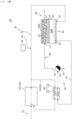
- the sweeping gas-supplying portion 30 is configured to supply the CO 2 -enriched gas as a constituent component for the sweeping gas from the carbon dioxide-capturing portion 10 to the liquid fuel-synthesizing portion 20.
- the sweeping gas-supplying portion 30 includes: a carbon dioxide-enriched gas-supplying pipe 32; a hydrogen-supplying pipe 34; and a hydrogen-producing portion 36.
- One end of the carbon dioxide-enriched gas-supplying pipe 32 is connected to the carbon dioxide-capturing portion 10, and the other end thereof is connected to the second supply port s2 of the liquid fuel-synthesizing portion 20.
- One end of the hydrogen-supplying pipe 34 is connected to the hydrogen-producing portion 36, and the other end thereof is connected to the carbon dioxide-enriched gas-supplying pipe 32.
- the heat exchange is performed between the heating medium (specifically, the CO 2 -enriched gas) flowing through the first flow path 62 and the second outflow gas flowing through the second flow path 64, and hence the heating medium is heated.
- the heating medium specifically, the CO 2 -enriched gas
- condensation heat can be utilized in the heat exchange, and the utilization can contribute to a further improvement in thermal efficiency.
- the temperature of the heating medium before the heat exchange is, for example, 5°C or more and 100°C or less, preferably 10°C or more and 80°C or less.
- the temperature of the heating medium after the heat exchange is, for example, 60°C or more and 200°C or less, preferably 90°C or more and 160°C or less.
- the temperature of the second outflow gas before the heat exchange is, for example, 150°C or more and 350°C or less, preferably 200°C or more and 300°C or less.
- the temperature of the second outflow gas (captured gas) after the heat exchange is, for example, 25°C or more and 250°C or less, preferably 50°C or more and 200°C or less.
- the concentration of the condensable gas in the second outflow gas before the heat exchange is, for example, 5 vol% or more and 50 vol% or less, preferably 10 vol% or more and 40 vol% or less.
- concentration of the condensable gas in the second outflow gas falls within the above-mentioned ranges, the heat exchange can be performed with higher efficiency.
- the drain trap 42 is arranged on the downstream side of the heat exchanger 60.
- the drain trap 42 separates a liquid (typically, water) condensed in the heat exchanger 60 and a gas from each other.
- the separated liquid is captured from the liquefied product-capturing pipe 43.
- the gas (captured gas) separated by the drain trap 42 contains the sweeping gas and hydrogen that has permeated through the water vapor separation membrane 24.
- the captured gas is supplied to the raw material gas-supplying portion 90 through the captured gas-supplying pipe 44.
- the raw material gas-supplying portion 90 includes a pressure-boosting portion or the like, and supplies the raw material gas at a desired pressure and a desired temperature to the liquid fuel-synthesizing portion 20.
- the captured gas is supplied as the raw material gas to the liquid fuel-synthesizing portion 20.
- the raw material gas may be prepared by being further mixed with, for example, the remaining raw material gas captured from the first outflow gas, hydrogen or carbon dioxide that is separately prepared, or a mixed gas thereof as required.
- the raw material gas may be completely free of the captured gas.
- the first outflow gas-capturing portion 80 captures the first outflow gas that has flowed out of the liquid fuel-synthesizing portion.
- the first outflow gas contains a condensable gas (the liquid fuel in the embodiment of FIG. 1B ) and the remaining raw material gas.
- the first outflow gas is subjected to gas-liquid separation into the remaining raw material gas and the condensable gas as required.
- the remaining raw material gas separated from the liquid fuel may be supplied to the raw material gas-supplying portion 90 to be reused as a constituent component for the raw material gas.
- liquid fuel-synthesizing portion 20 includes the water vapor separation membrane between the first gas flow path 20A and the second gas flow path 20B has been described above with reference to FIG. 1B .
- the above-mentioned description may be similarly applied to the embodiment in which the liquid fuel-synthesizing portion includes the liquid fuel separation membrane between the first gas flow path and the second gas flow path.
- the second outflow gas containing the liquid fuel that has permeated through the liquid fuel separation membrane and the sweeping gas is used in heat exchange with the heating medium, wherein the following is preferred: the sweeping gas contains the CO 2 -enriched gas; a liquid (typically, the liquid fuel) produced by condensation at the time of the heat exchange and a gas are separated from each other; the separated liquid is captured from the liquefied product-capturing pipe; and the separated gas (captured gas containing the sweeping gas) may be supplied to the raw material gas-supplying portion through the captured gas-supplying pipe.
- the first outflow gas containing water vapor and the remaining raw material gas is captured in the first outflow gas-capturing portion and subjected to gas-liquid separation, and the remaining raw material gas separated from the water vapor may be supplied to the raw material gas-supplying portion to be reused as a constituent component for the raw material gas.
- the liquid fuel-synthesizing portion is a membrane reactor.
- the portion is not limited to the configuration.
- the liquid fuel-synthesizing portion may be configured as follows: the portion includes a catalyst portion containing the catalyst and a separating portion, which includes the water vapor separation membrane, the non-permeation-side space, and the permeation-side space, as separate reactors in the stated order from its upstream side; a liquid fuel gas, a by-product gas (water vapor), and the remaining raw material gas that have flowed out of the catalyst portion flow into the non-permeation-side space of the separating portion; and the by-product gas and hydrogen that have permeated through the water vapor separation membrane flow as the second outflow gas out of the permeation-side space of the separating portion together with the sweeping gas.
- the gases that have flowed out of the catalyst portion flow as they are into the separating portion. Accordingly, the non-permeation-side space of the separating portion is regarded as forming the first gas flow path integrally with the catalyst portion, and the permeation-side space of the separating portion is regarded as the second gas flow path.
- the flow directions of the raw material gas and the sweeping gas in the side view of the water vapor separation membrane 24 are opposite to each other. However, those directions may be identical to each other.
- the reaction temperature of the step (III) is, for example, 180°C or more, preferably 200°C or more and 350°C or less.
- the pressure thereof is, for example, 1 MPa or more, preferably 2 MPa or more and 6 MPa or less.
- the flow velocity of the raw material gas is appropriately adjusted in accordance with, for example, a catalyst characteristic and a reactor form, and is, for example, 1,000/h or more and 50,000/h or less, preferably 2,000/h or more and 20,000/h or less, more preferably 3,000/h or more and 12,000/h or less in terms of gas hourly space velocity (GHSV) in a standard state (0°C and 1 atm).
- GHSV gas hourly space velocity
- the liquid fuel or water and the remaining raw material gas are separated and captured from the first outflow gas, and the remaining raw material gas is reused as part of the raw material gas in the step (III).
- a reactor for producing the liquid fuel, the catalyst, the water vapor separation membrane, the liquid fuel separation membrane, and the sweeping gas are as described in the section A.
- the liquid fuel production system and the method of producing a liquid fuel according to the embodiments of the present invention may each be suitably used in the production of a liquid fuel such as methanol.
Landscapes
- Chemical & Material Sciences (AREA)
- Oil, Petroleum & Natural Gas (AREA)
- Organic Chemistry (AREA)
- Engineering & Computer Science (AREA)
- General Chemical & Material Sciences (AREA)
- Chemical Kinetics & Catalysis (AREA)
- Analytical Chemistry (AREA)
- Hydrogen, Water And Hydrids (AREA)
- Separation Using Semi-Permeable Membranes (AREA)
Applications Claiming Priority (2)
| Application Number | Priority Date | Filing Date | Title |
|---|---|---|---|
| JP2022140350 | 2022-09-02 | ||
| PCT/JP2023/031432 WO2024048636A1 (ja) | 2022-09-02 | 2023-08-30 | 液体燃料製造システムおよび液体燃料の製造方法 |
Publications (1)
| Publication Number | Publication Date |
|---|---|
| EP4582516A1 true EP4582516A1 (en) | 2025-07-09 |
Family
ID=90099697
Family Applications (1)
| Application Number | Title | Priority Date | Filing Date |
|---|---|---|---|
| EP23860398.9A Pending EP4582516A1 (en) | 2022-09-02 | 2023-08-30 | Liquid fuel production system and liquid fuel production method |
Country Status (7)
| Country | Link |
|---|---|
| US (1) | US20250197732A1 (https=) |
| EP (1) | EP4582516A1 (https=) |
| JP (1) | JP7825057B2 (https=) |
| CN (1) | CN119790123A (https=) |
| AU (1) | AU2023334930A1 (https=) |
| TW (1) | TW202428855A (https=) |
| WO (1) | WO2024048636A1 (https=) |
Families Citing this family (2)
| Publication number | Priority date | Publication date | Assignee | Title |
|---|---|---|---|---|
| WO2026014060A1 (ja) * | 2024-07-11 | 2026-01-15 | 日本碍子株式会社 | 燃料製造システム |
| WO2026058761A1 (ja) * | 2024-09-12 | 2026-03-19 | 日本碍子株式会社 | 酸性ガスの回収方法 |
Family Cites Families (10)
| Publication number | Priority date | Publication date | Assignee | Title |
|---|---|---|---|---|
| JP4204273B2 (ja) | 2002-08-09 | 2009-01-07 | 日本碍子株式会社 | Ddr型ゼオライト膜複合体及びその製造方法 |
| KR100493158B1 (ko) | 2002-09-17 | 2005-06-02 | 삼성전자주식회사 | 적응적 하이브리드 arq 방법 및 적응적 하이브리드arq 시스템에 있어서 데이터 송수신방법 |
| JP2004202393A (ja) * | 2002-12-25 | 2004-07-22 | Tokyo Electric Power Co Inc:The | 二酸化炭素の脱着方法 |
| JP2007055970A (ja) * | 2005-08-26 | 2007-03-08 | Mitsui Eng & Shipbuild Co Ltd | メタノール製造用反応器及びメタノール製造方法 |
| US7717272B2 (en) | 2006-10-18 | 2010-05-18 | Ngk Insulators, Ltd. | Ceramic porous membrane and ceramic filter |
| JP7076229B2 (ja) * | 2018-03-08 | 2022-05-27 | Jfeスチール株式会社 | 二酸化炭素の再利用方法 |
| JP7430498B2 (ja) | 2018-08-02 | 2024-02-13 | 三菱ケミカル株式会社 | メタノールの製造方法 |
| WO2020027337A1 (ja) | 2018-08-02 | 2020-02-06 | 三菱ケミカル株式会社 | 接合体、それを有する分離膜モジュール及びアルコールの製造方法 |
| JP7151832B1 (ja) | 2021-06-11 | 2022-10-12 | Jfeスチール株式会社 | 膜反応器における未利用ガスの再利用方法 |
| WO2023112800A1 (ja) | 2021-12-17 | 2023-06-22 | 日本碍子株式会社 | 液体燃料合成システム及び液体燃料合成方法 |
-
2023
- 2023-08-30 JP JP2024544320A patent/JP7825057B2/ja active Active
- 2023-08-30 EP EP23860398.9A patent/EP4582516A1/en active Pending
- 2023-08-30 CN CN202380063002.2A patent/CN119790123A/zh active Pending
- 2023-08-30 WO PCT/JP2023/031432 patent/WO2024048636A1/ja not_active Ceased
- 2023-08-30 AU AU2023334930A patent/AU2023334930A1/en active Pending
- 2023-08-31 TW TW112132906A patent/TW202428855A/zh unknown
-
2025
- 2025-02-19 US US19/056,924 patent/US20250197732A1/en active Pending
Also Published As
| Publication number | Publication date |
|---|---|
| US20250197732A1 (en) | 2025-06-19 |
| JPWO2024048636A1 (https=) | 2024-03-07 |
| AU2023334930A1 (en) | 2025-02-20 |
| TW202428855A (zh) | 2024-07-16 |
| WO2024048636A1 (ja) | 2024-03-07 |
| JP7825057B2 (ja) | 2026-03-05 |
| CN119790123A (zh) | 2025-04-08 |
Similar Documents
| Publication | Publication Date | Title |
|---|---|---|
| US20250197732A1 (en) | Liquid fuel production system and liquid fuel production method | |
| US9138718B2 (en) | Compact catalytic membrane reactor for chemical process intensification | |
| Nomura et al. | Preparation of a stable silica membrane by a counter diffusion chemical vapor deposition method | |
| AU766490B2 (en) | Hydrogen-selective silica based membrane | |
| US7390347B2 (en) | Zeolite membranes for selective oxidation of carbon monoxide in mixed hydrogen gas source | |
| JP7850507B2 (ja) | 液体燃料合成システム及び液体燃料合成方法 | |
| US20250197751A1 (en) | Liquid fuel production system and liquid fuel production method | |
| US20250197750A1 (en) | Liquid fuel production system and liquid fuel production method | |
| US9486787B1 (en) | Method and apparatus for chemical process intensification | |
| US12599869B2 (en) | Gas separation method and gas separation apparatus | |
| CN115943194B (zh) | 液体燃料合成系统 | |
| WO2026014060A1 (ja) | 燃料製造システム | |
| CN117157379A (zh) | 液体燃料合成系统以及液体燃料合成方法 | |
| AU2023335011A1 (en) | Method for producing liquid fuel and liquid fuel synthesis system | |
| CN119855886A (zh) | 液体燃料的制造方法以及液体燃料合成系统 |
Legal Events
| Date | Code | Title | Description |
|---|---|---|---|
| STAA | Information on the status of an ep patent application or granted ep patent |
Free format text: STATUS: THE INTERNATIONAL PUBLICATION HAS BEEN MADE |
|
| PUAI | Public reference made under article 153(3) epc to a published international application that has entered the european phase |
Free format text: ORIGINAL CODE: 0009012 |
|
| STAA | Information on the status of an ep patent application or granted ep patent |
Free format text: STATUS: REQUEST FOR EXAMINATION WAS MADE |
|
| 17P | Request for examination filed |
Effective date: 20250213 |
|
| AK | Designated contracting states |
Kind code of ref document: A1 Designated state(s): AL AT BE BG CH CY CZ DE DK EE ES FI FR GB GR HR HU IE IS IT LI LT LU LV MC ME MK MT NL NO PL PT RO RS SE SI SK SM TR |
|
| DAV | Request for validation of the european patent (deleted) | ||
| DAX | Request for extension of the european patent (deleted) |