EP4582318A1 - Batteriewechselvorrichtung und batterielade- und wechselstation damit - Google Patents
Batteriewechselvorrichtung und batterielade- und wechselstation damit Download PDFInfo
- Publication number
- EP4582318A1 EP4582318A1 EP23858914.7A EP23858914A EP4582318A1 EP 4582318 A1 EP4582318 A1 EP 4582318A1 EP 23858914 A EP23858914 A EP 23858914A EP 4582318 A1 EP4582318 A1 EP 4582318A1
- Authority
- EP
- European Patent Office
- Prior art keywords
- battery
- locking
- driving
- lead screw
- bearing platform
- Prior art date
- Legal status (The legal status is an assumption and is not a legal conclusion. Google has not performed a legal analysis and makes no representation as to the accuracy of the status listed.)
- Pending
Links
Images


Classifications
-
- B—PERFORMING OPERATIONS; TRANSPORTING
- B60—VEHICLES IN GENERAL
- B60S—SERVICING, CLEANING, REPAIRING, SUPPORTING, LIFTING, OR MANOEUVRING OF VEHICLES, NOT OTHERWISE PROVIDED FOR
- B60S5/00—Servicing, maintaining, repairing, or refitting of vehicles
- B60S5/06—Supplying batteries to, or removing batteries from, vehicles
-
- B—PERFORMING OPERATIONS; TRANSPORTING
- B60—VEHICLES IN GENERAL
- B60L—PROPULSION OF ELECTRICALLY-PROPELLED VEHICLES; SUPPLYING ELECTRIC POWER FOR AUXILIARY EQUIPMENT OF ELECTRICALLY-PROPELLED VEHICLES; ELECTRODYNAMIC BRAKE SYSTEMS FOR VEHICLES IN GENERAL; MAGNETIC SUSPENSION OR LEVITATION FOR VEHICLES; MONITORING OPERATING VARIABLES OF ELECTRICALLY-PROPELLED VEHICLES; ELECTRIC SAFETY DEVICES FOR ELECTRICALLY-PROPELLED VEHICLES
- B60L53/00—Methods of charging batteries, specially adapted for electric vehicles; Charging stations or on-board charging equipment therefor; Exchange of energy storage elements in electric vehicles
- B60L53/80—Exchanging energy storage elements, e.g. removable batteries
-
- B—PERFORMING OPERATIONS; TRANSPORTING
- B60—VEHICLES IN GENERAL
- B60K—ARRANGEMENT OR MOUNTING OF PROPULSION UNITS OR OF TRANSMISSIONS IN VEHICLES; ARRANGEMENT OR MOUNTING OF PLURAL DIVERSE PRIME-MOVERS IN VEHICLES; AUXILIARY DRIVES FOR VEHICLES; INSTRUMENTATION OR DASHBOARDS FOR VEHICLES; ARRANGEMENTS IN CONNECTION WITH COOLING, AIR INTAKE, GAS EXHAUST OR FUEL SUPPLY OF PROPULSION UNITS IN VEHICLES
- B60K1/00—Arrangement or mounting of electrical propulsion units
- B60K1/04—Arrangement or mounting of electrical propulsion units of the electric storage means for propulsion
- B60K2001/0455—Removal or replacement of the energy storages
- B60K2001/0472—Removal or replacement of the energy storages from below
-
- B—PERFORMING OPERATIONS; TRANSPORTING
- B60—VEHICLES IN GENERAL
- B60Y—INDEXING SCHEME RELATING TO ASPECTS CROSS-CUTTING VEHICLE TECHNOLOGY
- B60Y2200/00—Type of vehicle
- B60Y2200/60—Industrial applications, e.g. pipe inspection vehicles
- B60Y2200/66—Containers; Pallets; Skids
-
- Y—GENERAL TAGGING OF NEW TECHNOLOGICAL DEVELOPMENTS; GENERAL TAGGING OF CROSS-SECTIONAL TECHNOLOGIES SPANNING OVER SEVERAL SECTIONS OF THE IPC; TECHNICAL SUBJECTS COVERED BY FORMER USPC CROSS-REFERENCE ART COLLECTIONS [XRACs] AND DIGESTS
- Y02—TECHNOLOGIES OR APPLICATIONS FOR MITIGATION OR ADAPTATION AGAINST CLIMATE CHANGE
- Y02T—CLIMATE CHANGE MITIGATION TECHNOLOGIES RELATED TO TRANSPORTATION
- Y02T10/00—Road transport of goods or passengers
- Y02T10/60—Other road transportation technologies with climate change mitigation effect
- Y02T10/70—Energy storage systems for electromobility, e.g. batteries
-
- Y—GENERAL TAGGING OF NEW TECHNOLOGICAL DEVELOPMENTS; GENERAL TAGGING OF CROSS-SECTIONAL TECHNOLOGIES SPANNING OVER SEVERAL SECTIONS OF THE IPC; TECHNICAL SUBJECTS COVERED BY FORMER USPC CROSS-REFERENCE ART COLLECTIONS [XRACs] AND DIGESTS
- Y02—TECHNOLOGIES OR APPLICATIONS FOR MITIGATION OR ADAPTATION AGAINST CLIMATE CHANGE
- Y02T—CLIMATE CHANGE MITIGATION TECHNOLOGIES RELATED TO TRANSPORTATION
- Y02T10/00—Road transport of goods or passengers
- Y02T10/60—Other road transportation technologies with climate change mitigation effect
- Y02T10/7072—Electromobility specific charging systems or methods for batteries, ultracapacitors, supercapacitors or double-layer capacitors
Definitions
- the above-mentioned patent provides the battery pack mounting and dismounting mechanism adaptable to batteries of different specifications and sizes.
- the torque guns of the battery pack mounting and dismounting mechanism disclosed in the patent are fixed to the tray body, and a bottom surface of the battery is generally lower than a bottom surface of a fastener.
- an idle torque gun will abut against the bottom surface of the battery, and will damage the battery.
- a great height difference between the bottom surface of the battery and the bottom surface of the fastener could not only lead to battery damage but also prevent the torque guns from properly engaging with the fasteners.
- the invention aims to solve the technical problem, that is, to solve the problem of poor compatibility of existing battery swapping devices.
- the invention provides a battery swapping device.
- the battery swapping device includes: a battery bearing platform, and a translation mechanism and a plurality of locking and unlocking mechanisms that are mounted on the battery bearing platform, where the translation mechanism is capable of driving at least some of the locking and unlocking mechanisms to move horizontally relative to the battery bearing platform, so as to enable the plurality of locking and unlocking mechanisms to adapt to traction batteries with different specifications.
- the battery swapping device further includes a lifting mechanism mounted on the battery bearing platform, where the lifting mechanism is configured to be capable of driving the at least some of the locking and unlocking mechanisms to move vertically relative to the battery bearing platform.
- the lifting mechanism includes a plurality of independent lifting driving units, and the lifting driving units are capable of driving corresponding locking and unlocking mechanisms to move vertically relative to the battery bearing platform.
- the translation mechanism is further configured to be capable of driving at least some of the lifting driving units and corresponding locking and unlocking mechanisms to synchronously move horizontally relative to the battery bearing platform.
- the translation mechanism includes a plurality of independent translation driving units, and the translation driving units are capable of driving corresponding lifting driving units and corresponding locking and unlocking mechanisms to synchronously move horizontally relative to the battery bearing platform.
- the translation driving unit includes a first driving assembly, a first lead screw and a translation member, and the lifting driving unit and the locking and unlocking mechanism that correspond to the translation driving unit are both mounted on the translation member;
- the battery swapping device further includes a first guide mechanism mounted between the battery bearing platform and the translation member, where the first guide mechanism is capable of guiding the translation member in a process of the translation member moving relative to the battery bearing platform.
- the first guide mechanism includes a first guide rail mounted on the battery bearing platform and a first guide block mounted on the translation member, the first guide rail is horizontally arranged in a movement direction of the translation member, and the first guide block is mounted on the first guide rail and is capable of sliding in a length direction of the first guide rail.
- the translation member includes a first movement block, a horizontal plate and a vertical plate, the first movement block is fixedly connected to the horizontal plate and is in threaded connection to the first lead screw, a top end of the vertical plate is fixedly connected to the horizontal plate, and the lifting driving unit and the locking and unlocking mechanism are mounted on the vertical plate.
- the lifting driving unit includes a second driving assembly, a second lead screw and a second movement block, and the second movement block is fixedly connected to the locking and unlocking mechanism; the second driving assembly and the second lead screw are both mounted on the vertical plate, the second lead screw is arranged in a vertical direction, and the second driving assembly is capable of driving the second lead screw to rotate; and the second movement block is mounted on the second lead screw and is in threaded connection to the second lead screw, and the second movement block is capable of moving vertically along the second lead screw along with rotation of the second lead screw.
- the invention further provides a battery charging and swapping station.
- the battery charging and swapping station is equipped with the battery swapping device described above.
- the battery swapping device of the invention has no excess locking and unlocking mechanism in the process of mounting and dismounting the battery, such that damage to the battery can be avoided.
- the excess locking and unlocking mechanism can be moved by the translation mechanism to a position away from the battery to prevent any potential damage to the battery.
- the lifting mechanism is preferably configured to drive the plurality of locking and unlocking mechanisms 2 to move vertically and independently from each other, so that positions of the locking and unlocking mechanisms 2 can be more advantageously adjusted, and adaption to batteries of more specification is achieved.
- all lifting mechanisms are preferably arranged at a lower side of the battery bearing platform 1.
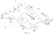
- twelve locking and unlocking mechanisms 2 are arranged on the battery bearing platform 1.
- Two locking and unlocking mechanisms 2 are arranged in a middle position of the battery bearing platform 1, and the battery bearing platform 1 is provided with one elongated opening 13 at each of positions corresponding to the two locking and unlocking mechanisms 2 (the elongated opening 13 allows a socket connector 21 of the locking and unlocking mechanism 2 to move freely).
- the two locking and unlocking mechanisms 2 are connected to both the translation mechanism and the lifting mechanism, that is, the two locking and unlocking mechanisms 2 can move horizontally relative to the battery bearing platform 1 and also move vertically relative to the battery bearing platform 1.
- the four locking and unlocking mechanisms 2 are arranged at a left end of the battery bearing platform 1, and the four locking and unlocking mechanisms 2 are merely connected to the lifting mechanism but not connected to the translation mechanism, that is, the four locking and unlocking mechanisms 2 can merely move vertically relative to the battery bearing platform 1.
- the other six locking and unlocking mechanisms 2 are distributed at other positions of the battery bearing platform 1.
- the six locking and unlocking mechanisms 2 are neither connected to the translation mechanism nor the lifting mechanism.
- all the twelve locking and unlocking mechanisms 2 may be connected to both the translation mechanism and the lifting mechanism, or some of the twelve locking and unlocking mechanisms 2 may be merely connected to the translation mechanism, and the rest may be merely connected to the lifting mechanism.
- Such flexible modifications and changes do not deviate from the principle and scope of the invention and should fall within the scope of protection of the invention.
- the lifting mechanism of the invention includes a plurality of independent lifting driving units 4, and the lifting driving units 4 are capable of driving corresponding locking and unlocking mechanisms 2 to move vertically relative to the battery bearing platform 1.
- the locking and unlocking mechanism 2 can move vertically relative to the battery bearing platform 1 independently.
- the lifting mechanism includes six independent lifting driving units 4, and each lifting driving unit 4 corresponds to one locking and unlocking mechanism 2, that is, six locking and unlocking mechanisms 2 may move vertically relative to the battery bearing platform 1.
- the translation mechanism of the invention is further configured to be capable of driving at least some of the lifting driving units 4 and corresponding locking and unlocking mechanisms 2 to synchronously move horizontally relative to the battery bearing platform 1.
- the "synchronously move horizontally” indicates that the lifting driving unit 4 and corresponding locking and unlocking mechanism 2 synchronously move horizontally under the drive of the translation mechanism.
- the lifting mechanism includes six independent lifting driving units 4, each lifting driving unit 4 corresponds to one unlocking mechanism 2.
- First and second lifting driving units 4 are connected to the translation mechanism. Under the drive of the translation mechanism, the first lifting driving unit 4 and a first locking and unlocking mechanism 2 may synchronously move horizontally relative to the battery bearing platform 1, and the second lifting driving unit 4 and a second locking and unlocking mechanism 2 may synchronously move horizontally relative to battery bearing platform 1.
- the first lifting driving unit 4 may drive the first locking and unlocking mechanism 2 to move vertically relative to battery bearing platform 1, and the second lifting driving unit 4 may drive the second locking and unlocking mechanism 2 to move vertically relative to battery bearing platform 1.
- the translation mechanism may be configured to be capable of driving the first lifting driving unit 4 and the second lifting driving unit 4 to move horizontally and independently from each other, or the translation mechanism may also be configured to be capable of driving the first lifting driving unit 4 and the second lifting driving unit 4 to move horizontally and synchronously with each other.
- the translation mechanism of the invention includes a plurality of independent translation driving units 3, and the translation driving units 3 are capable of driving corresponding lifting driving units 4 and corresponding locking and unlocking mechanisms 2 to synchronously move horizontally relative to the battery bearing platform 1.
- the translation mechanism includes two independent translation driving units 3.
- a first translation driving unit 3 may drive the first lifting driving unit 4 and the first locking and unlocking mechanism 2 to synchronously move horizontally relative to the battery bearing platform 1, and a second translation driving unit 3 may drive the second lifting driving unit 4 and the second locking and unlocking mechanism 2 to synchronously move horizontally relative to the battery bearing platform 1.
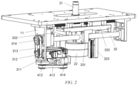
- the translation driving unit 3 of the invention includes a first driving assembly 31, a first lead screw 32 and a translation member 33, and the lifting driving unit 4 and the locking and unlocking mechanism 2 that correspond to the translation driving unit 3 are both mounted on the translation member 33.
- the first driving assembly 31 and the first lead screw 32 are both mounted on the battery bearing platform 1, the first lead screw 32 is arranged in a horizontal direction, and the first driving assembly 31 is capable of driving the first lead screw 32 to rotate.
- the translation member 33 is mounted on the first lead screw 32 and is in threaded connection to the first lead screw 32, and the translation member 33 is capable of driving, along the first lead screw 32 along with rotation of the first lead screw 32, the lifting driving unit 4 and the locking and unlocking mechanism 2 to move horizontally.
- the first lead screw 32 may be driven to rotate at first by the first driving assembly 31.
- the translation member 33 drive the lifting driving unit 4 and the locking and unlocking mechanism 2 to synchronously move horizontally.
- the lifting driving unit 4 drives the locking and unlocking mechanism 2 to move upwards, so as to lift the locking and unlocking mechanism 2 to a locking and unlocking position to engage with the fastener.
- the first driving assembly 31 may configure the first driving assembly 31 as a combined structure of a motor and a gear transmission system, or as a combined structure of a motor and a transmission belt, or as a combined structure of a motor and a sprocket chain.
- Such modifications and changes to the specific structural form of the first driving assembly 31 do not deviate from the principle and scope of the invention and should fall within the scope of protection of the invention.
- the first driving assembly 31 includes a first motor 311, a first driving gear 312, a first toothed transmission belt 313 and a first driven gear 314 that are mounted on the battery bearing platform 1.
- the first driving gear 312 is fixedly connected to a driving shaft of the first motor 311
- the first driven gear 314 is fixedly connected to an end of the first lead screw 32
- the first toothed transmission belt 313 meshes with the first driving gear 312 and the first driven gear 314.
- a bottom surface of the battery bearing platform 1 is provided with two first fixation plates 11 that are arranged opposite each other in the horizontal direction at a position corresponding to the first driving assembly 31, and two ends of the first lead screw 32 are rotatably connected to the two first fixation plates 11.
- the first motor 311 is mounted on one of the first fixation plates 11 and is located directly below the first lead screw 32, and the driving shaft of the first motor 311 is horizontally arranged.
- the first driving gear 312 is located directly below the first driven gear 314.
- the first motor 311 drives the first driving gear 312 to rotate.
- the first driving gear 312 drives the first driven gear 314 to rotate through the first toothed transmission belt 313, and the first driven gear 314 drives the first lead screw 32 to rotate.
- the battery swapping device of the invention further includes a first guide mechanism 5 mounted between the battery bearing platform 1 and the translation member 33.
- the first guide mechanism 5 is capable of guiding the translation member 33 in a process of the translation member 33 moving horizontally relative to the battery bearing platform 1.
- first guide mechanism 5 may configure the first guide mechanism 5 as a mechanism in which a guide column and a guide tube match each other, or may configure the first guide mechanism 5 as a mechanism in which a guide block and a guide rail match each other, or may configure the first guide mechanism 5 as a structure in which a guide recess and a guide block match each other.
- modifications and changes to the specific structural form of the first guide mechanism 5 do not deviate from the principle and scope of the invention and should fall within the scope of protection of the invention.
- the first guide mechanism 5 includes a first guide rail 51 mounted on the battery bearing platform 1 and a first guide block 52 mounted on the translation member 33, the first guide rail 51 is horizontally arranged in a movement direction of the translation member 33, and the first guide block 52 is mounted on the first guide rail 51 and is capable of sliding in a length direction of the first guide rail 51.
- a number of the first guide rails 51 is two, and the two first guide rails 51 are arranged in parallel.
- the two first guide rails are both fixedly mounted on the bottom surface of the battery bearing platform 1.
- a number of the first guide blocks 52 is also two, and the two first guide blocks 52 are both mounted on a top surface of the translation member 33.
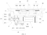
- the translation member 33 includes a first movement block 331, a horizontal plate 332 and a vertical plate 333, the first movement block 331 is fixedly connected to the horizontal plate 332 and is in threaded connection to the first lead screw 32, a top end of the vertical plate 333 is fixedly connected to the horizontal plate 332, and the lifting driving unit 4 and the locking and unlocking mechanism 2 are both mounted on the vertical plate 333.
- a threaded hole (not shown in the figure) is provided in the first movement block 331.
- the first movement block 331 is in threaded connection to the first lead screw 32 through the threaded hole.
- a top end of the first movement block 331 is fixedly connected to a bottom surface of the horizontal plate 332, and the first guide block 52 is mounted on a top surface of the horizontal plate 332.
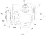
- the lifting driving unit 4 of the invention includes a second driving assembly 41, a second lead screw 42 and a second movement block 43, and the second movement block 43 is fixedly connected to the locking and unlocking mechanism 2.
- the second driving assembly 41 and the second lead screw 42 are both mounted on the vertical plate 333, the second lead screw 42 is arranged in a vertical direction, and the second driving assembly 41 is capable of driving the second lead screw 42 to rotate.
- the second movement block 43 is mounted on the second lead screw 42 and is in threaded connection to the second lead screw 42, and the second movement block 43 is capable of driving, along the second lead screw 42 along with rotation of the second lead screw 42, the locking and unlocking mechanism 2 to move vertically.
- the bottom surface of the battery bearing platform 1 is provided with two second fixation plates 12 that are arranged opposite each other in the horizontal direction at a position corresponding to the lifting driving unit 4, and the locking and unlocking mechanism 2 is located between the two second fixation plates 12.
- the second driving assembly 41 and the second lead screw 42 of the lifting driving unit 4 are both mounted on one of the second fixation plates 12.
- the battery swapping device further includes a third guide mechanism 7 mounted between the second fixation plate 12 and the locking and unlocking mechanism 2, and the third guide mechanism 7 may guide the locking and unlocking mechanism 2 in a process of the locking and unlocking mechanism 2 moving vertically relative to the second fixation plate 12.
- the third guide mechanism 7 includes two sets of third guide rails 71 and third guide blocks 72 matching each other.
- the third guide rails 71 are arranged in the vertical direction, and the third guide blocks 72 are capable of sliding vertically along the third guide rails 71.
- the two third guide rails 71 are fixedly connected to corresponding second fixation plates 12, respectively, and the two third guide blocks 72 are fixedly connected to two opposite sides of the locking and unlocking mechanism 2, respectively.
- the locking and unlocking mechanism 2 of the invention includes a third driving assembly and a socket connector 21, and the third driving assembly is connected to the socket connector 21 and is capable of driving the socket connector 21 to rotate.
- the socket connector 21 matches the fastener of the traction battery in shape. After completion of engagement of the socket connector 21 with the fastener, the third driving assembly drives the socket connector 21 to drive the fastener to rotate, so as to unlock or tighten the fastener.
- the third driving assembly of the invention includes a third motor 22 and a speed reducer 23, a bottom end of the speed reducer 23 is fixedly connected to a driving shaft of the third motor 22, and a top end of the speed reducer 23 is connected to the socket connector 21.
- a housing of the speed reducer 23 may be fixedly connected to the second movement block 43 and the second guide block 62.
Landscapes
- Engineering & Computer Science (AREA)
- Mechanical Engineering (AREA)
- Power Engineering (AREA)
- Transportation (AREA)
- Battery Mounting, Suspending (AREA)
Applications Claiming Priority (2)
| Application Number | Priority Date | Filing Date | Title |
|---|---|---|---|
| CN202211073713.1A CN115257658A (zh) | 2022-09-02 | 2022-09-02 | 换电装置及包括该换电装置的充换电站 |
| PCT/CN2023/104967 WO2024045876A1 (zh) | 2022-09-02 | 2023-06-30 | 换电装置及包括该换电装置的充换电站 |
Publications (2)
| Publication Number | Publication Date |
|---|---|
| EP4582318A1 true EP4582318A1 (de) | 2025-07-09 |
| EP4582318A4 EP4582318A4 (de) | 2025-12-17 |
Family
ID=83754898
Family Applications (1)
| Application Number | Title | Priority Date | Filing Date |
|---|---|---|---|
| EP23858914.7A Pending EP4582318A4 (de) | 2022-09-02 | 2023-06-30 | Batteriewechselvorrichtung und batterielade- und wechselstation damit |
Country Status (3)
| Country | Link |
|---|---|
| EP (1) | EP4582318A4 (de) |
| CN (1) | CN115257658A (de) |
| WO (1) | WO2024045876A1 (de) |
Families Citing this family (6)
| Publication number | Priority date | Publication date | Assignee | Title |
|---|---|---|---|---|
| CN115257658A (zh) * | 2022-09-02 | 2022-11-01 | 蔚来汽车科技(安徽)有限公司 | 换电装置及包括该换电装置的充换电站 |
| CN116279320A (zh) * | 2023-02-28 | 2023-06-23 | 奇瑞新能源汽车股份有限公司 | 一种换电电池包、换电站和换电兼容方法 |
| CN117401608B (zh) * | 2023-10-20 | 2024-03-29 | 嘉善志达机电有限公司 | 一种智能换电平台 |
| CN118494413A (zh) * | 2024-03-05 | 2024-08-16 | 蔚来汽车科技(安徽)有限公司 | 换电设施的换电定位方法、系统及换电设施 |
| CN117962824A (zh) * | 2024-03-15 | 2024-05-03 | 蔚来汽车科技(安徽)有限公司 | 换电机器人及充换电站 |
| CN222157425U (zh) * | 2024-03-15 | 2024-12-13 | 蔚来汽车科技(安徽)有限公司 | 换电机器人及充换电站 |
Family Cites Families (14)
| Publication number | Priority date | Publication date | Assignee | Title |
|---|---|---|---|---|
| CN106627515A (zh) * | 2016-12-29 | 2017-05-10 | 西安航天精密机电研究所 | 一种底盘式电池解锁移载装置 |
| SG11201907017QA (en) * | 2016-12-30 | 2019-09-27 | Shanghai Dianba New Energy Technology Co Ltd | Movable battery replacing platform and quick replacing system |
| CN108177635A (zh) * | 2017-12-15 | 2018-06-19 | 蔚来汽车有限公司 | 充换电站 |
| CN108177634A (zh) * | 2017-12-15 | 2018-06-19 | 蔚来汽车有限公司 | 充换电站 |
| CN111745657A (zh) * | 2019-03-29 | 2020-10-09 | 中立元(镇江)电动汽车加电科技有限公司 | 一种用于不同车型的电动小客车的智能换电机器人 |
| CN112389917B (zh) * | 2019-08-16 | 2023-01-06 | 北京新能源汽车股份有限公司 | 换电方法 |
| JP6741323B1 (ja) * | 2019-11-11 | 2020-08-19 | 祐次 廣田 | Ev用蓄電池の自動交換システム |
| CN111231752A (zh) * | 2020-01-23 | 2020-06-05 | 奥动新能源汽车科技有限公司 | 换电设备 |
| CN111873849B (zh) * | 2020-07-17 | 2023-01-06 | 蓝谷智慧(北京)能源科技有限公司 | 电动汽车的换电方法 |
| CN113370837A (zh) * | 2021-07-20 | 2021-09-10 | 重庆峘能电动车科技有限公司 | 基于多轴联动的换电系统 |
| CN113386617A (zh) * | 2021-08-05 | 2021-09-14 | 安徽巨一科技股份有限公司 | 多车型电池加解锁机构 |
| CN216761517U (zh) | 2021-12-02 | 2022-06-17 | 奥动新能源汽车科技有限公司 | 电池包拆装机构和包含其的换电机器人 |
| CN218085463U (zh) * | 2022-09-02 | 2022-12-20 | 蔚来汽车科技(安徽)有限公司 | 换电装置及包括该换电装置的充换电站 |
| CN115257658A (zh) * | 2022-09-02 | 2022-11-01 | 蔚来汽车科技(安徽)有限公司 | 换电装置及包括该换电装置的充换电站 |
-
2022
- 2022-09-02 CN CN202211073713.1A patent/CN115257658A/zh active Pending
-
2023
- 2023-06-30 EP EP23858914.7A patent/EP4582318A4/de active Pending
- 2023-06-30 WO PCT/CN2023/104967 patent/WO2024045876A1/zh not_active Ceased
Also Published As
| Publication number | Publication date |
|---|---|
| EP4582318A4 (de) | 2025-12-17 |
| WO2024045876A1 (zh) | 2024-03-07 |
| CN115257658A (zh) | 2022-11-01 |
Similar Documents
| Publication | Publication Date | Title |
|---|---|---|
| EP4582318A1 (de) | Batteriewechselvorrichtung und batterielade- und wechselstation damit | |
| CN115431732B (zh) | 电动汽车 | |
| CN111469705B (zh) | 一种换电站及电池更换方法 | |
| US6109424A (en) | Chassis/body marriage lift machine | |
| EP4578722A1 (de) | Batterielade- und wechselstation | |
| CN218085463U (zh) | 换电装置及包括该换电装置的充换电站 | |
| EP3725606A1 (de) | Batterielade- und wechselstation | |
| CN112659962A (zh) | 电池的拆装推拉装置及电池拆装系统 | |
| KR20120092661A (ko) | 모터 차량 구동용 모터에 전력을 공급하는 배터의 교체 장치 | |
| CN214001412U (zh) | 载车平台及包括其的换电站 | |
| CN218085459U (zh) | 换电装置及包括该换电装置的充换电站 | |
| CN111775764B (zh) | 一种车辆定位装置及换电站 | |
| CN118219908A (zh) | 用于换电站的换电方法 | |
| CN115743665B (zh) | 一种机械换电的无人机机库 | |
| KR101082292B1 (ko) | 충방전용 이차전지 셀 고정장치 및 그를 구비한 지그 | |
| CN215644777U (zh) | 一种拉出式蓄电池箱的折叠导轨及使用该导轨的电池箱 | |
| CN115891930A (zh) | 一种电动卡车换电站 | |
| KR102744927B1 (ko) | 하네스 케이블의 자동 조립시스템용 웨이빙장치 | |
| KR102744924B1 (ko) | 하네스 케이블용 자동 정렬장치 | |
| CN219278783U (zh) | 一种电池模组柔性搬运夹具 | |
| CN216761507U (zh) | 提高电池转运设备升降稳定性的限位机构及电池转运设备 | |
| CN115284939B (zh) | 提高电池转运设备升降稳定性的限位机构及电池转运设备 | |
| CN115283980B (zh) | 套筒装置、扭矩枪及换电机器人 | |
| CN114683920B (zh) | 电池转运设备的传动机构及电池转运系统 | |
| CN217426834U (zh) | 一种间距可调的化成装置 |
Legal Events
| Date | Code | Title | Description |
|---|---|---|---|
| STAA | Information on the status of an ep patent application or granted ep patent |
Free format text: STATUS: THE INTERNATIONAL PUBLICATION HAS BEEN MADE |
|
| PUAI | Public reference made under article 153(3) epc to a published international application that has entered the european phase |
Free format text: ORIGINAL CODE: 0009012 |
|
| STAA | Information on the status of an ep patent application or granted ep patent |
Free format text: STATUS: REQUEST FOR EXAMINATION WAS MADE |
|
| 17P | Request for examination filed |
Effective date: 20250130 |
|
| AK | Designated contracting states |
Kind code of ref document: A1 Designated state(s): AL AT BE BG CH CY CZ DE DK EE ES FI FR GB GR HR HU IE IS IT LI LT LU LV MC ME MK MT NL NO PL PT RO RS SE SI SK SM TR |
|
| STAA | Information on the status of an ep patent application or granted ep patent |
Free format text: STATUS: EXAMINATION IS IN PROGRESS |
|
| DAV | Request for validation of the european patent (deleted) | ||
| DAX | Request for extension of the european patent (deleted) | ||
| A4 | Supplementary search report drawn up and despatched |
Effective date: 20251117 |
|
| RIC1 | Information provided on ipc code assigned before grant |
Ipc: B60S 5/06 20190101AFI20251111BHEP |
|
| 17Q | First examination report despatched |
Effective date: 20251128 |