EP4582214A1 - Truck for welding work, welding work system, and welding work method - Google Patents
Truck for welding work, welding work system, and welding work method Download PDFInfo
- Publication number
- EP4582214A1 EP4582214A1 EP23859883.3A EP23859883A EP4582214A1 EP 4582214 A1 EP4582214 A1 EP 4582214A1 EP 23859883 A EP23859883 A EP 23859883A EP 4582214 A1 EP4582214 A1 EP 4582214A1
- Authority
- EP
- European Patent Office
- Prior art keywords
- welding
- carriage
- machine
- main body
- rail
- Prior art date
- Legal status (The legal status is an assumption and is not a legal conclusion. Google has not performed a legal analysis and makes no representation as to the accuracy of the status listed.)
- Pending
Links
Images

Classifications
-
- B—PERFORMING OPERATIONS; TRANSPORTING
- B23—MACHINE TOOLS; METAL-WORKING NOT OTHERWISE PROVIDED FOR
- B23K—SOLDERING OR UNSOLDERING; WELDING; CLADDING OR PLATING BY SOLDERING OR WELDING; CUTTING BY APPLYING HEAT LOCALLY, e.g. FLAME CUTTING; WORKING BY LASER BEAM
- B23K37/00—Auxiliary devices or processes, not specially adapted for a procedure covered by only one of the other main groups of this subclass
- B23K37/02—Carriages for supporting the welding or cutting element
-
- B—PERFORMING OPERATIONS; TRANSPORTING
- B23—MACHINE TOOLS; METAL-WORKING NOT OTHERWISE PROVIDED FOR
- B23K—SOLDERING OR UNSOLDERING; WELDING; CLADDING OR PLATING BY SOLDERING OR WELDING; CUTTING BY APPLYING HEAT LOCALLY, e.g. FLAME CUTTING; WORKING BY LASER BEAM
- B23K31/00—Processes relevant to this subclass, specially adapted for particular articles or purposes, but not covered by any single one of main groups B23K1/00 - B23K28/00
- B23K31/12—Processes relevant to this subclass, specially adapted for particular articles or purposes, but not covered by any single one of main groups B23K1/00 - B23K28/00 relating to investigating the properties, e.g. the weldability, of materials
- B23K31/125—Weld quality monitoring
-
- B—PERFORMING OPERATIONS; TRANSPORTING
- B23—MACHINE TOOLS; METAL-WORKING NOT OTHERWISE PROVIDED FOR
- B23K—SOLDERING OR UNSOLDERING; WELDING; CLADDING OR PLATING BY SOLDERING OR WELDING; CUTTING BY APPLYING HEAT LOCALLY, e.g. FLAME CUTTING; WORKING BY LASER BEAM
- B23K37/00—Auxiliary devices or processes, not specially adapted for a procedure covered by only one of the other main groups of this subclass
- B23K37/02—Carriages for supporting the welding or cutting element
- B23K37/0211—Carriages for supporting the welding or cutting element travelling on a guide member, e.g. rail, track
- B23K37/0217—Carriages for supporting the welding or cutting element travelling on a guide member, e.g. rail, track the guide member being fixed to the workpiece
-
- B—PERFORMING OPERATIONS; TRANSPORTING
- B23—MACHINE TOOLS; METAL-WORKING NOT OTHERWISE PROVIDED FOR
- B23K—SOLDERING OR UNSOLDERING; WELDING; CLADDING OR PLATING BY SOLDERING OR WELDING; CUTTING BY APPLYING HEAT LOCALLY, e.g. FLAME CUTTING; WORKING BY LASER BEAM
- B23K37/00—Auxiliary devices or processes, not specially adapted for a procedure covered by only one of the other main groups of this subclass
- B23K37/02—Carriages for supporting the welding or cutting element
- B23K37/0247—Driving means
-
- B—PERFORMING OPERATIONS; TRANSPORTING
- B23—MACHINE TOOLS; METAL-WORKING NOT OTHERWISE PROVIDED FOR
- B23K—SOLDERING OR UNSOLDERING; WELDING; CLADDING OR PLATING BY SOLDERING OR WELDING; CUTTING BY APPLYING HEAT LOCALLY, e.g. FLAME CUTTING; WORKING BY LASER BEAM
- B23K37/00—Auxiliary devices or processes, not specially adapted for a procedure covered by only one of the other main groups of this subclass
- B23K37/02—Carriages for supporting the welding or cutting element
- B23K37/0282—Carriages forming part of a welding unit
-
- B—PERFORMING OPERATIONS; TRANSPORTING
- B23—MACHINE TOOLS; METAL-WORKING NOT OTHERWISE PROVIDED FOR
- B23K—SOLDERING OR UNSOLDERING; WELDING; CLADDING OR PLATING BY SOLDERING OR WELDING; CUTTING BY APPLYING HEAT LOCALLY, e.g. FLAME CUTTING; WORKING BY LASER BEAM
- B23K37/00—Auxiliary devices or processes, not specially adapted for a procedure covered by only one of the other main groups of this subclass
- B23K37/02—Carriages for supporting the welding or cutting element
- B23K37/0294—Transport carriages or vehicles
-
- B—PERFORMING OPERATIONS; TRANSPORTING
- B23—MACHINE TOOLS; METAL-WORKING NOT OTHERWISE PROVIDED FOR
- B23K—SOLDERING OR UNSOLDERING; WELDING; CLADDING OR PLATING BY SOLDERING OR WELDING; CUTTING BY APPLYING HEAT LOCALLY, e.g. FLAME CUTTING; WORKING BY LASER BEAM
- B23K9/00—Arc welding or cutting
- B23K9/12—Automatic feeding or moving of electrodes or work for spot or seam welding or cutting
Definitions
- a welding carriage includes: a carriage main body including a securing surface to which one operation machine is secured, the one operation machine being selected from different types of operation machines that perform different welding operations; a wheel that is supported by the carriage main body and brought into contact with a surface of a workpiece that is a welding target; a motor that operates to move the carriage main body on the surface of the workpiece; and carriage control circuitry that controls the motor, wherein the carriage main body removably receives the operation machine that is secured to the securing surface.
- a welding method includes: preparing a welding carriage, the welding carriage including a carriage main body including a securing surface to which one operation machine is secured, the one operation machine being selected from different types of operation machines that perform different welding operations, and a wheel that is supported by the carriage main body and brought into contact with a surface of a workpiece that is a welding target; securing to the securing surface a first operation machine for a first operation to be performed; performing the first operation by the first operation machine while moving the welding carriage; after completion of the first operation, changing the operation machine secured to the securing surface from the first operation machine to a second operation machine for a second operation to be subsequently performed; and performing the second operation by the second operation machine while moving the welding carriage.
- the carriage 2 includes a motor 8 that operates to move the carriage main body 4 on the surface of the workpiece W.
- the motor 8 is located in the enclosure 7.
- the motor 8 is supplied with electric power delivered from an external source through a power cable 50.
- the carriage 2 may be equipped with a battery.
- the rail holder 9 includes two roller pairs.
- the rotational axes of the drive and driven rollers 11 and 12 are perpendicular to the securing surface 6.
- the paired rollers are located on the opposite sides of the recess 10. That is, the paired rollers hold the rail R therebetween in the left-right direction.
- the rail holder 9 further includes a second auxiliary roller 17 attached to an arm 16 extending from the enclosure 7, the second auxiliary roller 17 being located across the rail R from the first auxiliary roller 15 in the direction perpendicular to the securing surface 6.
- the arm 16 is located outside a side surface of the enclosure 7.
- the second auxiliary roller 17 is tilted relative to the direction perpendicular to the securing surface 6.
- the rail holder 9 includes two first auxiliary rollers 15 and two second auxiliary rollers 17.
- the first auxiliary rollers 15 are located above the rail R.
- the second auxiliary rollers 17 are located obliquely below the rail R.
- the arm 16 biases the second auxiliary roller 17 toward the first auxiliary roller 15.
- the arm 16 is attached to a shaft 18 secured to the enclosure 7 and pivotable about the shaft 18.
- the second auxiliary roller 17 is attached to the distal end of the arm 16.
- a biasing force-adjusting pin 19 is secured to the arm 16.
- a biasing force-adjusting screw 20 in contact with the biasing force-adjusting pin 19 is supported by the enclosure 7. Fastening the biasing force-adjusting screw 20 causes the arm 16 to pivot about the shaft 18, thus increasing the force with which the second auxiliary roller 17 presses the rail R.
- the drive rollers 11 are rotated by drive power of the motor 8, with the rail R held between the paired rollers 11 and 12, and this rotation causes the welding carriage 2 to move along the rail R.
- the wheels 5a and 5b rotate in contact with the workpiece W.
- the welding carriage 2 can be moved along the rail R to perform a given welding operation on the workpiece W by the operation machine 3 mounted on the welding carriage 2, not only in case that the surface of the workpiece W faces upward but also in case that the surface of the workpiece W faces laterally or downward.
- the wheels 5a and 5b include a first wheel 5a located in a first direction orthogonal to the rail R with respect to the carriage main body 4 and a second wheel 5b located in a second direction opposite to the first direction with respect to the carriage main body 4.
- the first direction is a direction in which the drive rollers 11 of the paired rollers are located with respect to the rail R
- the second direction is a direction in which the driven rollers 12 of the paired rollers are located with respect to the rail R.
- the carriage main body 4 includes a first support 22 secured to the enclosure 7 and a second support 23 rotatably supporting the first wheel 5a.
- the second support 23 is connected to the first support 22 via an elastic element 24 and is extendable and retractable.
- the first wheel 5a is biased by the elastic force of the elastic element 24 in a direction from the carriage main body 4 toward the surface of the workpiece W.
- the biasing force acting on the first wheel 5a can be adjusted by a biasing force-adjusting screw 25.
- the second wheel 5b is rotatably supported by a support 21 secured to the enclosure 7.
- the carriage 2 includes a position detector 43 that detects the position of the carriage main body 4.
- the position detector 43 detects the distance moved by the carriage 2 from a given reference position.
- the reference position can be set by a user and may be, for example, a predetermined operation starting position.
- the position detector 43 includes a first encoder that detects the number of rotations made by the driven rollers 12 after the start of movement from the reference position. The distance moved by the carriage 2 can be determined from the diameter and the number of rotations of the driven rollers 12. Thus, the position of the carriage main body 4 can be identified.
- the carriage 2 further includes a slippage detector 44 that detects the amount of deviation of the distance moved by the carriage main body 4 per unit rotation of the motor 8 from a reference value.
- the slippage detector 44 includes a first encoder that detects the number of rotations made by the driven rollers 12 after the start of movement from the reference position and a second encoder that detects the number of rotations made by the drive rollers 11 after the start of movement from the reference position. The number of rotations made by the driven rollers 12 per unit time is determined from the value detected by the first encoder, and the number of rotations made by the drive rollers 11 per unit time is determined from the value detected by the second encoder.
- the amount of deviation of the distance moved by the carriage main body 4 per unit rotation of the motor 8 from the reference value namely, the amount of slippage of the drive rollers 11 relative to the rail R, can be determined.
- the operation machine 3 is a welding machine.
- the welding machine includes a welding machine main body 30 that is secured to the securing surface 6, a welding oscillator 32, and a wire reel 33 on which is wound a welding wire that is a wire-shaped filler metal.
- the wire reel 33 is secured to the welding machine main body 30 via a first arm 34 extending from the welding machine main body 30 in the first direction.
- the welding oscillator 32 is secured to the welding machine main body 30 via a second arm 35 extending from the welding machine main body 30 in the second direction opposite to the first direction.
- the first direction in which the first arm 34 extends is a direction that is orthogonal to the rail R and extends toward the first wheel 5a, with the welding machine main body 30 secured to the securing surface 6 of the carriage main body 4.
- the second direction in which the second arm 35 extends is a direction that is orthogonal to the rail R and extends toward the second wheel 5b, with the welding machine main body 30 secured to the securing surface 6 of the carriage main body 4.
- the welding machine shown in the example of FIG. 1 is, for example, a consumable electrode-type welding machine such as a MIG welder, a MAG welder, or a FCAW welder.
- the welding oscillator 32 includes a welding torch 31 having an electrode 36 at its distal end.
- the electrode 36 of the welding torch 31 is directed toward the welding target.
- the electrode 36 is a welding wire 37 fed from the wire reel 33.
- the welding torch 31 includes a nozzle that delivers a shielding gas to the welding target.
- An electric wire extending from a power source is connected to the welding torch 31, to which electric power is delivered through the electric wire.
- the workpiece W as the welding target includes two pieces to be welded together.
- the two pieces are placed end-to-end and there is a groove Gr in the region where a welding joint is to be formed.
- the groove Gr is such that with the two pieces placed end-to-end, their groove surfaces form a given groove angle. Considering that in some cases the region of contact between the two pieces may be curved, the term "groove angle" is intended to refer to the angle at which extensions of the groove surfaces intersect each other.
- the shape of the groove Gr is selected as appropriate from various shapes.
- the welding machine is placed in a position where the distal end of the electrode 36 of the welding torch 31 is directed toward the groove Gr of the workpiece W.
- the welding machine includes a horizontal rail 38 extending in a direction horizontal to the workpiece W and a vertical rail 39 extending in a direction vertical to the workpiece W.
- the welding torch 31 is mounted to the horizontal rail 38 and slidable on the horizontal rail 38 in the horizontal direction.
- the horizontal rail 38 is mounted to the vertical rail 39 and slidable on the vertical rail 39 in the vertical direction.
- the welding machine includes an actuator that moves each of the welding torch 31 and the horizontal rail 38 individually.
- the moving structure for the welding torch 31 is not limited to this configuration.
- the moving structure may be configured using an articulated robot that includes a distal part equipped with the welding torch 31.
- FIG. 3 is a block diagram showing a schematic configuration of a control system of the welding system shown in FIG. 1 .
- the carriage control circuitry 26, the control panel 28, the motor 8, an interface 42, the position detector 43, and the slippage detector 44 are connected to, and able to exchange signals with, one another via a bus 45.
- the welding machine control circuitry 40, the control panel 41, the welding oscillator 32, the wire reel 33, an interface 46, and a current detector 47 are connected to, and able to exchange signals with, one another via a bus 48.
- Each of the processors 26a and 40a includes, for example, a computer such as a microcontroller, a personal computer, or a PLC (Programmable Logic Controller).
- each of the processors includes processing circuitry such as a CPU or MPU, a register, a RAM, and peripheral circuitry.
- the welding machine control circuitry 40 may send a control command for the carriage 2 to the carriage control circuitry 26.
- the carriage control circuitry 26 may send a control command for the operation machine 3 to the welding machine control circuitry 40.
- the different types of operation machines 3 include: a welding machine as described above which includes the welding torch 31 and performs welding while moving the welding torch 31; a processing machine that performs a process related to welding; and an inspection machine that performs an inspection before or after welding. Furthermore, the different types of operation machines 3 include different types of welding machines that perform different types of welding. For example, the welding machine A is a MIG welder, the welding machine B is a FCAW welder, and the welding machine C is a TIG welder. The different types of welding machines may further include other welding machines such as a MAG welder and a plasma welder. For example, in the case where the operation machine 3 is a non-consumable electrode-type welding machine such as a TIG welder or a plasma welder, the operation machine 3 may include a voltage detector that detects an arc voltage.
- the different types of operation machines 3 also include different types of processing machines that perform different types of processes.
- the processing machine D is a grinder that grinds a weld bead
- the processing machine E is a back chipping machine that cuts the back side of the groove Gr of the workpiece W by machining
- the processing machine F is a gouging machine that gouges the back side of the groove Gr of the workpiece W by means of a plasma.
- the different types of processing machines may further include other processing machines.
- the welding system 1 includes at least two operation machines as the different types of operation machines 3.
- the at least two operation machines may be at least two operation machines selected from the same category; for example, the at least two operation machines may include the welding machine A and the welding machine B.
- the at least two operation machines may be at least two operation machines selected from different categories; for example, the at least two operation machines may include the welding machine A and the processing machine D.
- two or more of the three or more operation machines may be selected from the same category and two or more of the three or more operation machines may be selected from different categories; for example, the three or more operation machines may include the welding machine A, the welding machine B, and the processing machine D.
- the rail R is secured along the direction in which the groove Gr of the workpiece W extends.
- the carriage 2 is caused to hold the rail R.
- a first operation machine which is a welding machine is secured to the securing surface 6 of the carriage main body 4.
- the carriage 2 is moved, and along with the movement of the carriage 2 a welding operation is performed as a first operation by the first operation machine.
- the first operation machine is removed from the carriage main body 4, and the operation machine secured to the securing surface 6 of the carriage main body 4 is changed to a second operation machine for a second operation to be subsequently performed.
- the carriage 2 may keep holding the rail R.
- the second operation machine is a grinder that grinds a bead.
- the carriage 2 with the grinder secured to the securing surface 6 is moved, and along with the movement of the carriage 2 a bead grinding operation is performed as the second operation by the second operation machine.
- the second operation machine is removed from the carriage main body 4, and the operation machine secured to the securing surface 6 of the carriage main body 4 is changed to a third operation machine for a third operation to be subsequently performed.
- the third operation machine is an inspection machine that performs a non-destructive inspection on the bead.
- the rail R is secured to the back side of the workpiece W along the direction in which the groove Gr extends.
- the carriage 2 is caused to hold the rail R.
- a fourth operation machine is secured to the securing surface 6 of the carriage main body 4.
- the fourth operation machine is a back chipping machine.
- the carriage 2 is moved, and along with the movement of the carriage 2 a back chipping operation is performed as a fourth operation by the fourth operation machine.
- the fact that the same moving structure can be used in combination with different types of operation machines allows the different types of operation machines to be used in a standardized way. This increases the ease of use for users, resulting in improved welding quality. Moreover, since the same moving structure can be used in combination with different types of operation machines, the burden involved in replacing the operation machine 3 for each welding operation can be reduced. This can lead to improved efficiency of the whole welding operations, reduced man-hours, and shortened lead time.
- the carriage control circuitry 26 that controls the carriage 2 is communicatively connected to the operation machine 3 secured to the securing surface 6, detection data acquired from detectors such as the position detector 43 that detects the position of the carriage main body 4 or control data related to the control performed by the carriage control circuitry 26 on the carriage 2 can be used in the operation machine 3.
- the operation machine 3 secured to the securing surface 6 is a welding machine
- the welding machine can be controlled such that the welding machine starts to perform a welding operation at the same time as the carriage 2 starts to move and that the welding operation by the welding machine is ended at the same time as the carriage 2 comes to a stop after having moved a predetermine distance.
- the carriage control circuitry 26 can acquire detection data or control data related to the operation machine 3 and control the movement of the carriage 2 based on the acquired data.
- the welding operation can be efficiently accomplished by virtue of the fact that the communication connection between the carriage control circuitry 26 and the operation machine 3 enables the carriage 2 and the operation machine 3 to work in cooperation with each other as described above.
- the storage 26b of the carriage control circuitry 26 can accumulate data acquired from different operation machines 3.
- the data accumulated from each of the operation machines 3 are stored in association with other data such as position data of the carriage 2.
- the accumulated data can easily be made mutually available to the different operation machines.
- welding data in the welding machine A and non-destructive inspection data in the inspection machine G may be associated with each other; in this case, data on the welding conditions at the site of a weld defect can be collected.
- inspection result data acquired by the inspection machine J that performs an instruction for the shape of the groove before welding may be referenced by the welding machine A.
- the welding machine A can change the welding conditions according to the shape of the groove.
- traceability can be established between different types of welding operations. This can eliminate or reduce the need for monitoring in the welding system 1.
- the carriage 2 holds the rail R secured to the surface of the workpiece W and moves along the rail R.
- the rail R is positioned to extend in the direction of the welding line of the workpiece W; thus, appropriate tracking motion in the direction of the welding line of the groove Gr of the workpiece W can be achieved by moving the carriage 2 holding the rail R.
- the rail R is held by the rail holder 9, the operation using the operation machine 3 can be effected irrespective of the direction in which the carriage 2 is oriented relative to a horizontal plane.
- the workpiece W has a curved portion and there is a variation in the angle of the surface of the workpiece W with respect to the ground. Even in this case, the presence of the rail holder 9 holding the rail R allows the operation machine 3 secured to the carriage 2 to continuously perform the welding operation over the entirety of the workpiece W.
- the rail R is held between the pair of rollers 11 and 12, and one of the paired rollers, namely the driven roller 12, is pressed by the presser 14 toward the other drive roller 11.
- the drive roller 11 is actuated by the motor 8.
- the drive roller 11 actuated is pressed against the rail R by the pressing action of the presser 14; thus, the drive power of the drive roller 11 can be reliably transmitted to the rail R, and appropriate movement of the carriage 2 can be achieved irrespective of the orientation of the carriage 2.
- the slippage detector 44 detects the amount of deviation of the distance moved by the carriage main body 4 per unit rotation of the motor 8 from a reference value.
- the carriage 2 can assume various orientations; for this reason, the amount of slippage of the drive roller 11 relative to the rail R, and therefore the efficiency of transmission of drive power from the drive roller 11 actuated by the motor 8 to the rail R, can vary even when the drive power itself remains unchanged.
- the fact that the slippage detector 44 detects the degree of slippage as the amount of deviation of the distance moved by the carriage main body 4 from the reference value enables correction of the position to which the carriage 2 moves.
- the position of the carriage 2 that can assume various orientations can be precisely controlled.
- the rail R is circular in cross-section, and this permits pivotal motion of the carriage 2 about the axis of the rail R.
- the first wheel 5a which is one of the first and second wheels 5a and 5b in contact with the workpiece W and which is located in the first direction orthogonal to the rail R with respect to the carriage main body 4, is biased in a direction from the carriage main body 4 toward the surface of the workpiece W.
- the carriage 2 can pivot in the circumferential direction of the rail R which is circular in cross-section.
- the carriage 2 can move along the rail R in conformity with the surface of the workpiece W. That is, the carriage main body 4 can be reliably kept in contact with the surface of the workpiece W irrespective of the orientation of the carriage 2. This makes it possible for the operation machine 3 mounted on the carriage 2 to properly perform the operation on the workpiece W.
- the presser 14 may be configured to adjust the pressure for pressing the driven roller 12 toward the drive roller 11 based on a control command from the carriage control circuitry 26. Furthermore, the carriage control circuitry 26 may generate the control command for adjusting the pressure applied by the presser 14 according to the amount of deviation detected by the slippage detector 44. Controlling the presser 14 to reduce the amount of deviation can lead to a reduction in the speed change of the carriage 2 which occurs due to the motor 8 being controlled based on the amount of deviation.
- the first wheel 5a of the wheels 5a and 5b is biased in a direction from the carriage main body 4 toward the surface of the workpiece W. Additionally or alternatively, the second wheel 5b may be biased in a direction from the carriage main body 4 toward the surface of the workpiece W.
- the carriage 2 or the operation machine 3 may include, for example, a common control panel for manipulating the carriage 2 and the operation machine 3.
- the carriage 2 or the operation machine 4 may include a remote manipulation terminal separate from the carriage main body 4 or the main body of the operation machine 4 and operable to remotely manipulate the carriage 2 or the operation machine 4.
- the remote manipulation terminal is connected to the carriage main body 4 or the main body of the operation machine 4 by wire or wirelessly.
- the remote manipulation terminal may be a communication terminal such as a smartphone which is capable of communication through a network such as the Internet.
- the carriage control circuitry 26 is communicatively connected to the operation machine 3 secured to the securing surface 6 of the carriage main body 4, the carriage control circuitry 26 and the operation machine 3 need not be communicatively connected to each other.
- the operation machine 3 secured to the securing surface 6 need not include any control circuitry.
- the different operation machines may include a processing machine that starts to run upon receiving electric power.
- Such a processing machine may include a power on/off button independent of the carriage 2 and start to run once the on/off button is turned on.
- An operation machine having a communication function or a control function need not be communicatively connected to the carriage control circuitry 26.
- a welding carriage includes: a carriage main body including a securing surface to which one operation machine is secured, the one operation machine being selected from different types of operation machines that perform different welding operations; a wheel that is supported by the carriage main body and brought into contact with a surface of a workpiece that is a welding target; a motor that operates to move the carriage main body on the surface of the workpiece; and carriage control circuitry that controls the motor, wherein the carriage main body removably receives the operation machine that is secured to the securing surface.
- an operation machine selected from different types of operation machines is secured to one welding carriage, and the secured operation machine is used to perform a welding operation.
- the same welding carriage which is movable relative to the workpiece can be used for different types of welding operations.
- the same moving structure can be used in combination with different types of operation machines, the cost for manufacturing or maintenance of the different types of operation machines can be reduced.
- the carriage main body may include a rail holder that holds a rail secured to the surface of the workpiece and extending in a direction of a welding line of the workpiece.
- the welding carriage holds the rail secured to the surface of the workpiece and moves along the rail.
- the rail is positioned to extend in the direction of the welding line of the workpiece; thus, appropriate tracking motion in the direction of the welding line of the groove of the workpiece can be achieved by moving the welding carriage which is holding the rail.
- the operation using the operation machine can be effected irrespective of the direction in which the welding carriage is oriented relative to a horizontal plane.
- the carriage control circuitry may be communicatively connected to the operation machine.
- detection data or control data related to the welding carriage can be used in the operation machine secured to the securing surface, while detection data or control data related to the secured operation machine can be used in the welding carriage.
- the welding operation can be efficiently accomplished by virtue of the fact that the communication connection between the carriage control circuitry and the operation machine enables the welding carriage and the operation machine to work in cooperation with each other.
- the welding carriage according to any one of items 1 to 7 may further include a position detector that detects a position of the carriage main body, and the carriage control circuitry may control the motor based on the detected position of the carriage main body.
- the welding carriage according to any one of items 1 to 9 may further include a slippage detector that detects an amount of deviation of a distance moved by the carriage main body per unit rotation of the motor from a reference value.
- the configuration in which the slippage detector detects the degree of slippage as the amount of deviation of the distance moved by the carriage main body from the reference value enables correction of the position to which the welding carriage moves.
- the position of the welding carriage that can assume various orientations can be precisely controlled.
- the different types of operation machines may include: a welding machine that includes a welding torch and performs welding while moving the welding torch; a processing machine that performs a process related to welding; or an inspection machine that performs an inspection before or after welding.
- a welding method includes: preparing a welding carriage, the welding carriage including a carriage main body including a securing surface to which one operation machine is secured, the one operation machine being selected from different types of operation machines that perform different welding operations, and a wheel that is supported by the carriage main body and brought into contact with a surface of a workpiece that is a welding target; securing to the securing surface a first operation machine for a first operation to be performed; performing the first operation by the first operation machine while moving the welding carriage; after completion of the first operation, changing the operation machine secured to the securing surface from the first operation machine to a second operation machine for a second operation to be subsequently performed; and performing the second operation by the second operation machine while moving the welding carriage.
Landscapes
- Engineering & Computer Science (AREA)
- Mechanical Engineering (AREA)
- Physics & Mathematics (AREA)
- Optics & Photonics (AREA)
- Quality & Reliability (AREA)
- Plasma & Fusion (AREA)
- Butt Welding And Welding Of Specific Article (AREA)
- Arc Welding In General (AREA)
- Handcart (AREA)
Abstract
Description
- The present disclosure relates to a welding carriage, a welding system, and a welding method.
- In the welding work, not only a welding machine which actually performs welding, but also various processing machines which shape the weld bead formed on the workpiece by the welding machine and gauge the back side of the groove, and inspection machines for performing inspections before and after welding, are used.
- For example, in order to automate various welding operations performed in production of a large-sized structure, the welding machine, the processing machines, the inspection machines etc. need to be configured as self-propelled automatic machines, and each of the machines such as the welding machine needs to be automatically moved along the welding line of the groove of the workpiece while performing a corresponding one of the operations.
- For example,
Patent Literature 1 discloses a welding machine having a welding torch mounted to a self-propelled carriage.Patent Literature 2 discloses a processing machine having a machining cutter attached to a self-propelled carriage to grind a weld bead. -
- PTL 1:
Japanese Laid-Open Patent Application Publication No. 2008-302386 - PTL 2:
Japanese Utility Model Registration No. 3192280 - However, such a conventional configuration as mentioned above requires changing the machine to be automatically moved depending on the contents of the intended one of welding operations even when all of the welding operations are performed along a single welding line. This machine replacement process is cumbersome.
- It is therefore an object of the present disclosure to provide a welding carriage, a welding system, and a welding method that allow for simple implementation of different types of welding operations.
- A welding carriage according to one aspect of the present disclosure includes: a carriage main body including a securing surface to which one operation machine is secured, the one operation machine being selected from different types of operation machines that perform different welding operations; a wheel that is supported by the carriage main body and brought into contact with a surface of a workpiece that is a welding target; a motor that operates to move the carriage main body on the surface of the workpiece; and carriage control circuitry that controls the motor, wherein the carriage main body removably receives the operation machine that is secured to the securing surface.
- A welding system according to another aspect of the present disclosure includes: the above welding carriage; and the different types of operation machines securable to the securing surface, wherein the different types of operation machines include: a welding machine that includes a welding torch and performs welding while moving the welding torch; a processing machine that performs a process related to welding; or an inspection machine that performs an inspection before or after welding.
- A welding method according to another aspect of the present disclosure includes: preparing a welding carriage, the welding carriage including a carriage main body including a securing surface to which one operation machine is secured, the one operation machine being selected from different types of operation machines that perform different welding operations, and a wheel that is supported by the carriage main body and brought into contact with a surface of a workpiece that is a welding target; securing to the securing surface a first operation machine for a first operation to be performed; performing the first operation by the first operation machine while moving the welding carriage; after completion of the first operation, changing the operation machine secured to the securing surface from the first operation machine to a second operation machine for a second operation to be subsequently performed; and performing the second operation by the second operation machine while moving the welding carriage.
- The present disclosure allows for simple implementation of different types of welding operations.
-
-
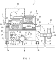
FIG. 1 is a front view showing a schematic configuration of a welding system according to one embodiment of the present disclosure. -
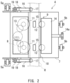
FIG. 2 is a bottom view of the carriage main body shown inFIG. 1 . -
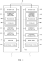
FIG. 3 is a block diagram showing a schematic configuration of a control system of the welding system shown inFIG. 1 . -
FIG. 4 is an image diagram showing different types of operation machines that can be secured to the welding carriage according to the present embodiment. - The following will describe a welding system including a welding carriage according to one embodiment of the present disclosure.
-
FIG. 1 is a front view showing a schematic configuration of the welding system according to one embodiment of the present disclosure. InFIG. 1 , a workpiece W that is a welding target is positioned horizontally, and thewelding system 1 is located on a surface of the workpiece W. Thus, in the following description, a portion of thewelding system 1 that is relatively far from the surface of the workpiece W is an upper portion, while a portion of thewelding system 1 that is relatively close to the surface of the workpiece W is a lower portion. - In the present embodiment, the
welding system 1 includes awelding carriage 2 and anoperation machine 3 mounted on thewelding carriage 2. Hereinafter, thewelding carriage 2 is also simply referred to as thecarriage 2. Thecarriage 2 includes a carriagemain body 4 andwheels main body 4. The carriagemain body 4 includes asecuring surface 6 to which theoperation machine 3 is secured. The carriagemain body 4 includes anenclosure 7 in the shape of a rectangular parallelepiped. The upper surface of theenclosure 7 serves as thesecuring surface 6. Thewheels - The
carriage 2 includes amotor 8 that operates to move the carriagemain body 4 on the surface of the workpiece W. Themotor 8 is located in theenclosure 7. Themotor 8 is supplied with electric power delivered from an external source through apower cable 50. Alternatively, thecarriage 2 may be equipped with a battery. - In the present embodiment, a rail R is secured to the surface of the workpiece W along a welding line. The securing of the rail R is not limited to using particular means. For example, the rail R may be secured to the workpiece W by welding, by a magnet, or by a vacuum pad. The rail R is circular in cross-section. For example, the rail R is a pipe rail. The carriage
main body 4 includes arail holder 9 that holds the rail R. Theenclosure 7 includes arecess 10 in its lower surface which is opposite to thesecuring surface 6, and the rail R is inserted in therecess 10. Therecess 10 is arc-shaped in cross-section. Therail holder 9 is located around therecess 10. -
FIG. 2 is a bottom view of the carriage main body shown inFIG. 1 . Therail holder 9 includes a pair of rollers between which the rail R is held. The pair of rollers includes adrive roller 11 actuated by themotor 8 and a drivenroller 12 opposed to thedrive roller 11. The carriagemain body 4 includes alink 13 that transmits drive power of themotor 8 to thedrive roller 11 to rotate thedrive roller 11. Thelink 13 includes, for example, a gear box. - There are two
drive rollers 11 arranged in the direction in which the rail R extends, and there are two drivenrollers 12 arranged in the direction in which the rail R extends. That is, therail holder 9 includes two roller pairs. The rotational axes of the drive and drivenrollers securing surface 6. The paired rollers are located on the opposite sides of therecess 10. That is, the paired rollers hold the rail R therebetween in the left-right direction. - The
rail holder 9 includes apresser 14 that presses the drivenrollers 12 toward thedrive rollers 11. In the present embodiment, thepresser 14 includes apressing adjuster 14a, and thepressing adjuster 14a is operated to change the distance from the drivenrollers 12 to thedrive rollers 11. Bringing the drivenrollers 12 closer to thedrive rollers 11 with the rail R held between the drive and drivenrollers rollers - The driven
rollers 12 are made of a resin less elastic than the material of thedrive rollers 11. For example, thedrive rollers 11 used may be rollers each of which includes an elastomer layer serving as a contact surface that contacts the rail R. The drivenrollers 12 used may be resin rollers each of which includes no elastomer layer serving as a contact surface that contacts the rail R. Alternatively, rollers made of a material that is not less elastic than the material of thedrive rollers 11 may be used as the drivenrollers 12. The materials of the drive and drivenrollers - In the present embodiment, the
rail holder 9 includes a firstauxiliary roller 15 located at the bottom surface of therecess 10, namely, above the lower surface of theenclosure 7. The firstauxiliary roller 15 has a rotational axis parallel to the securingsurface 6 and orthogonal to the longitudinal direction of therecess 10, i.e., the direction in which the rail R extends. The firstauxiliary roller 15 is located in correspondence with the pair ofrollers recess 10. - The
rail holder 9 further includes a secondauxiliary roller 17 attached to anarm 16 extending from theenclosure 7, the secondauxiliary roller 17 being located across the rail R from the firstauxiliary roller 15 in the direction perpendicular to the securingsurface 6. Thearm 16 is located outside a side surface of theenclosure 7. The secondauxiliary roller 17 is tilted relative to the direction perpendicular to the securingsurface 6. Therail holder 9 includes two firstauxiliary rollers 15 and two secondauxiliary rollers 17. The firstauxiliary rollers 15 are located above the rail R. The secondauxiliary rollers 17 are located obliquely below the rail R. - The
arm 16 biases the secondauxiliary roller 17 toward the firstauxiliary roller 15. Thearm 16 is attached to ashaft 18 secured to theenclosure 7 and pivotable about theshaft 18. The secondauxiliary roller 17 is attached to the distal end of thearm 16. A biasing force-adjustingpin 19 is secured to thearm 16. A biasing force-adjustingscrew 20 in contact with the biasing force-adjustingpin 19 is supported by theenclosure 7. Fastening the biasing force-adjustingscrew 20 causes thearm 16 to pivot about theshaft 18, thus increasing the force with which the secondauxiliary roller 17 presses the rail R. - In the present embodiment, as described above, the
drive rollers 11 are rotated by drive power of themotor 8, with the rail R held between the pairedrollers welding carriage 2 to move along the rail R. During this movement, thewheels rail holder 9, thewelding carriage 2 can be moved along the rail R to perform a given welding operation on the workpiece W by theoperation machine 3 mounted on thewelding carriage 2, not only in case that the surface of the workpiece W faces upward but also in case that the surface of the workpiece W faces laterally or downward. - The
wheels first wheel 5a located in a first direction orthogonal to the rail R with respect to the carriagemain body 4 and asecond wheel 5b located in a second direction opposite to the first direction with respect to the carriagemain body 4. In the present embodiment, the first direction is a direction in which thedrive rollers 11 of the paired rollers are located with respect to the rail R, while the second direction is a direction in which the drivenrollers 12 of the paired rollers are located with respect to the rail R. - The carriage
main body 4 includes afirst support 22 secured to theenclosure 7 and asecond support 23 rotatably supporting thefirst wheel 5a. Thesecond support 23 is connected to thefirst support 22 via anelastic element 24 and is extendable and retractable. Thefirst wheel 5a is biased by the elastic force of theelastic element 24 in a direction from the carriagemain body 4 toward the surface of the workpiece W. The biasing force acting on thefirst wheel 5a can be adjusted by a biasing force-adjustingscrew 25. Thesecond wheel 5b is rotatably supported by asupport 21 secured to theenclosure 7. - As shown in
FIG. 3 described later, thecarriage 2 includes aposition detector 43 that detects the position of the carriagemain body 4. For example, theposition detector 43 detects the distance moved by thecarriage 2 from a given reference position. The reference position can be set by a user and may be, for example, a predetermined operation starting position. For example, theposition detector 43 includes a first encoder that detects the number of rotations made by the drivenrollers 12 after the start of movement from the reference position. The distance moved by thecarriage 2 can be determined from the diameter and the number of rotations of the drivenrollers 12. Thus, the position of the carriagemain body 4 can be identified. - Alternatively, the
position detector 43 may include a timer that measures the time elapsing after the start of movement from the reference position. In case that themotor 8 is rotated at a constant speed and the amount of slippage described below is 0, the distance moved by thecarriage 2 can be determined from the time for which themotor 8 runs after the start of movement from the reference position. Thus, the position of the carriagemain body 4 can be identified. Alternatively, theposition detector 43 may include a second encoder that detects the number of rotations made by thedrive rollers 11 after the start of movement from the reference position. - As shown in
FIG. 3 described later, thecarriage 2 further includes aslippage detector 44 that detects the amount of deviation of the distance moved by the carriagemain body 4 per unit rotation of themotor 8 from a reference value. For example, theslippage detector 44 includes a first encoder that detects the number of rotations made by the drivenrollers 12 after the start of movement from the reference position and a second encoder that detects the number of rotations made by thedrive rollers 11 after the start of movement from the reference position. The number of rotations made by the drivenrollers 12 per unit time is determined from the value detected by the first encoder, and the number of rotations made by thedrive rollers 11 per unit time is determined from the value detected by the second encoder. By finding the difference between the determined numbers of rotations per unit time, the amount of deviation of the distance moved by the carriagemain body 4 per unit rotation of themotor 8 from the reference value, namely, the amount of slippage of thedrive rollers 11 relative to the rail R, can be determined. - The
slippage detector 44 may be devoid of the second encoder. In this case, the number of rotations made by thedrive rollers 11 per unit time may be calculated from the rotational speed of themotor 8. The rotational speed of themotor 8 may be detected by an encoder that detects the rotational speed of the output shaft of themotor 8 or may be determined using a control command value given to themotor 8. - To a portion of the securing
surface 6 of the carriagemain body 4 is secured acase 27 on whichcarriage control circuitry 26 is mounted. Thecarriage 2 includes acontrol panel 28 located on the upper surface of thecase 27 to manipulate thecarriage 2 for welding operations. Thecarriage control circuitry 26 controls themotor 8. Thecarriage control circuitry 26 acquires data detected by theposition detector 43 and theslippage detector 44. Thecarriage control circuitry 26 controls themotor 8 based on the detected position of the carriagemain body 4. Thecarriage control circuitry 26 controls themotor 8 also based on the detected amount of deviation. For example, thecarriage control circuitry 26 changes the rotational speed of themotor 8 according to the amount of deviation. Thecarriage control circuitry 26 may calculate the amount of deviation from the detection value obtained by theslippage detector 44. Alternatively, theslippage detector 44 may include a calculator that calculates the amount of deviation independently of thecarriage control circuitry 26. - The
operation machine 3 is removably secured to the securingsurface 6. The securingsurface 6 includes securingholes 6a. Theoperation machine 3 is secured to the securingsurface 6 by securingscrews 29 inserted in the securingholes 6a. Theoperation machine 3 can be removed from the securingsurface 6 of the carriagemain body 4 by loosening the securing screws 29. - In the example of
FIG. 1 , theoperation machine 3 is a welding machine. The welding machine includes a welding machinemain body 30 that is secured to the securingsurface 6, awelding oscillator 32, and awire reel 33 on which is wound a welding wire that is a wire-shaped filler metal. Thewire reel 33 is secured to the welding machinemain body 30 via afirst arm 34 extending from the welding machinemain body 30 in the first direction. Thewelding oscillator 32 is secured to the welding machinemain body 30 via asecond arm 35 extending from the welding machinemain body 30 in the second direction opposite to the first direction. The first direction in which thefirst arm 34 extends is a direction that is orthogonal to the rail R and extends toward thefirst wheel 5a, with the welding machinemain body 30 secured to the securingsurface 6 of the carriagemain body 4. The second direction in which thesecond arm 35 extends is a direction that is orthogonal to the rail R and extends toward thesecond wheel 5b, with the welding machinemain body 30 secured to the securingsurface 6 of the carriagemain body 4. - The welding machine shown in the example of
FIG. 1 is, for example, a consumable electrode-type welding machine such as a MIG welder, a MAG welder, or a FCAW welder. Thewelding oscillator 32 includes awelding torch 31 having anelectrode 36 at its distal end. Theelectrode 36 of thewelding torch 31 is directed toward the welding target. Theelectrode 36 is awelding wire 37 fed from thewire reel 33. Thewelding torch 31 includes a nozzle that delivers a shielding gas to the welding target. An electric wire extending from a power source is connected to thewelding torch 31, to which electric power is delivered through the electric wire. - The workpiece W as the welding target includes two pieces to be welded together. The two pieces are placed end-to-end and there is a groove Gr in the region where a welding joint is to be formed. The groove Gr is such that with the two pieces placed end-to-end, their groove surfaces form a given groove angle. Considering that in some cases the region of contact between the two pieces may be curved, the term "groove angle" is intended to refer to the angle at which extensions of the groove surfaces intersect each other. The shape of the groove Gr is selected as appropriate from various shapes. The welding machine is placed in a position where the distal end of the
electrode 36 of thewelding torch 31 is directed toward the groove Gr of the workpiece W. - In the present embodiment, the welding machine includes a
horizontal rail 38 extending in a direction horizontal to the workpiece W and avertical rail 39 extending in a direction vertical to the workpiece W. Thewelding torch 31 is mounted to thehorizontal rail 38 and slidable on thehorizontal rail 38 in the horizontal direction. Thehorizontal rail 38 is mounted to thevertical rail 39 and slidable on thevertical rail 39 in the vertical direction. The welding machine includes an actuator that moves each of thewelding torch 31 and thehorizontal rail 38 individually. The moving structure for thewelding torch 31 is not limited to this configuration. For example, the moving structure may be configured using an articulated robot that includes a distal part equipped with thewelding torch 31. - The welding machine includes welding
machine control circuitry 40 that controls thewelding oscillator 32 and thewire reel 33. The weldingmachine control circuitry 40 is mounted within the welding machinemain body 30. The welding machine includes acontrol panel 41 located on the upper surface of the welding machinemain body 30 to manipulate the welding machine. -
FIG. 3 is a block diagram showing a schematic configuration of a control system of the welding system shown inFIG. 1 . In thecarriage 2, as shown inFIG. 3 , thecarriage control circuitry 26, thecontrol panel 28, themotor 8, an interface 42, theposition detector 43, and theslippage detector 44 are connected to, and able to exchange signals with, one another via abus 45. In the welding machine as theoperation machine 3, the weldingmachine control circuitry 40, thecontrol panel 41, thewelding oscillator 32, thewire reel 33, aninterface 46, and acurrent detector 47 are connected to, and able to exchange signals with, one another via abus 48. - The
interfaces 42 and 46 establish communication connections to external devices. In the present embodiment, theinterfaces 42 and 46 are connected by acommunication cable 49. Thus, thecarriage control circuitry 26 is communicatively connected to theoperation machine 3, and this enables data exchange etc. between thecarriage control circuitry 26 and the weldingmachine control circuitry 40. Alternatively, thecarriage control circuitry 26 and the weldingmachine control circuitry 40 may be configured to wirelessly communicate with each other. - The
carriage control circuitry 26 includes aprocessor 26a and astorage 26b. Thestorage 26b stores data acquired from thedetectors storage 26b further stores a control program for control of themotor 8 and therefore control of the movement of thecarriage 2. Likewise, the weldingmachine control circuitry 40 includes aprocessor 40a and astorage 40b. Thestorage 40b stores data acquired from thecurrent detector 47. Thestorage 40b further stores a control program for control of thewelding oscillator 32 and thewire reel 33. - Each of the
processors - The functionality of the elements disclosed herein may be implemented using circuitry or processing circuitry which includes general purpose processors, special purpose processors, integrated circuits, ASICs (Application Specific Integrated Circuits), FPGAs (Field Programmable Gate Arrays), conventional circuitry or combinations thereof which are configured or programmed to perform the disclosed functionality. Processors are considered processing circuitry or circuitry as they include transistors and other circuitry therein. In the present disclosure, the circuitry, units, or means are hardware that carry out or are programmed to perform the recited functionality. The hardware may be any hardware disclosed herein or otherwise known hardware which is programmed or configured to carry out the recited functionality. When the hardware is a processor which may be considered a type of circuitry, the circuitry, means, or units are a combination of hardware and software, the software being used to configure the hardware or processor.
- Since the
carriage control circuitry 26 and the weldingmachine control circuitry 40 are communicatively connected as described above, thecarriage control circuitry 26 can transmit the following data to the welding machine control circuitry 40: position data indicating the position of the carriagemain body 4 detected by theposition detector 43 mounted on thecarriage 2; and control data such as the amount of deviation detected by theslippage detector 44 or the current speed of thecarriage 2. - The welding
machine control circuitry 40 causes the welding machine to perform a basic action in which thewelding torch 31 is periodically moved over a given weaving width in the width direction of the groove Gr of the workpiece W and at the same time moved in the direction of the welding line of the workpiece W at a given torch height to track the welding line of the workpiece W. Thus, the weldingmachine control circuitry 40 can control thewelding oscillator 32 and thewire reel 33 appropriately based on the state of the movement of thecarriage 2 by acquiring data on the state of the movement of thecarriage 2 in the direction of the welding line of the workpiece W from thecarriage control circuitry 26. - For example, the welding
machine control circuitry 40 may change the welding conditions in the welding machine based on the position of the carriagemain body 4 detected by theposition detector 43 or the amount of deviation detected by theslippage detector 44. For example, parameters defining the welding conditions may include the welding current, the weaving width, the weaving period, the end-point stop time, the middle-point stop time, the welding speed, and the feed speed of thewelding wire 37. The welding current is an electric current supplied to theelectrode 36 of thewelding torch 31. In the case where the welding is pulse welding in which the voltage is increased and decreased at given time intervals, the peak current and the base current may be set as welding parameters related to the welding current. - The weaving width is the amount of movement of the
welding torch 31 in the width direction of the groove Gr of the workpiece W. The weaving period is the period with which thewelding torch 31 performs weaving motion in the width direction of the groove Gr. The end-point stop time is the time from when thewelding torch 31 reaches one end point of the weaving motion in the groove width direction until thewelding torch 31 begins to turn back toward the other end point of the weaving motion in the groove width direction. The middle-point stop time is the time for which thewelding torch 31 remains stopped at the middle point of the weaving motion in the groove width direction. These stop times may be 0; that is, thewelding torch 31 need not be stopped during the weaving motion. The welding speed is the speed at which thewelding torch 31 moves in the direction of the welding line, namely, the speed of movement of thecarriage 2. The feed speed of thewelding wire 37 is the speed at which thewelding wire 37 is fed from thewire reel 33 to thewelding torch 31. - Furthermore, the welding
machine control circuitry 40 can send the following data to the carriage control circuitry 26: data acquired by thecurrent detector 47 mounted on the welding machine; and control data related to control of the welding machine. Thus, thecarriage control circuitry 26 can control the movement of thecarriage 2 based on the state of control of the welding machine. - The
current detector 47 detects the welding current flowing through theelectrode 36 of thewelding torch 31. When the welding machine is of the consumable electrode type, the welding machine is controlled to bring the welding current to a suitable level. In this case, the controlled parameters include not only the weaving width, the torch height, and the wire feed speed which are controllable in the welding machine but also the speed of movement in the direction of the welding line. Thus, thecarriage control circuitry 26 can control the movement of thecarriage 2 based on data acquired by thecurrent detector 47. - The welding
machine control circuitry 40 may send a control command for thecarriage 2 to thecarriage control circuitry 26. Thecarriage control circuitry 26 may send a control command for theoperation machine 3 to the weldingmachine control circuitry 40. - The carriage
main body 4 removably receives theoperation machine 3 that is secured to the securingsurface 6. Theoperation machine 3 to be secured to the securingsurface 6 of the carriagemain body 4 is not limited to the welding machine illustrated inFIG. 1 but selected from different types of operation machines that perform different welding operations.FIG. 4 is an image diagram showing different types of operation machines that can be secured to the welding carriage according to the present embodiment. - The different types of
operation machines 3 include: a welding machine as described above which includes thewelding torch 31 and performs welding while moving thewelding torch 31; a processing machine that performs a process related to welding; and an inspection machine that performs an inspection before or after welding. Furthermore, the different types ofoperation machines 3 include different types of welding machines that perform different types of welding. For example, the welding machine A is a MIG welder, the welding machine B is a FCAW welder, and the welding machine C is a TIG welder. The different types of welding machines may further include other welding machines such as a MAG welder and a plasma welder. For example, in the case where theoperation machine 3 is a non-consumable electrode-type welding machine such as a TIG welder or a plasma welder, theoperation machine 3 may include a voltage detector that detects an arc voltage. - The different types of
operation machines 3 also include different types of processing machines that perform different types of processes. For example, the processing machine D is a grinder that grinds a weld bead, the processing machine E is a back chipping machine that cuts the back side of the groove Gr of the workpiece W by machining, and the processing machine F is a gouging machine that gouges the back side of the groove Gr of the workpiece W by means of a plasma. The different types of processing machines may further include other processing machines. - The different types of
operation machines 3 also include different types of inspection machines that perform different types of inspections. For example, the inspection machine G is an RT inspection machine that performs a non-destructive inspection by means of radiation, and the inspection machine H is a UT inspection machine that performs a non-destructive inspection by means of ultrasound. The inspection machine J is an inspection machine that performs an inspection for the shape of the groove before welding. The different types of inspection machines may further include other inspection machines such as an MT inspection machine that performs a non-destructive inspection by means of magnetism and an inspection machine that performs an inspection for the visual shape of a weld bead. - The
welding system 1 includes at least two operation machines as the different types ofoperation machines 3. The at least two operation machines may be at least two operation machines selected from the same category; for example, the at least two operation machines may include the welding machine A and the welding machine B. Alternatively, the at least two operation machines may be at least two operation machines selected from different categories; for example, the at least two operation machines may include the welding machine A and the processing machine D. In the case where three or more operation machines are prepared, two or more of the three or more operation machines may be selected from the same category and two or more of the three or more operation machines may be selected from different categories; for example, the three or more operation machines may include the welding machine A, the welding machine B, and the processing machine D. - The following will describe an example of welding operation procedures performed using the
welding system 1 configured as described above. First, the rail R is secured along the direction in which the groove Gr of the workpiece W extends. Thecarriage 2 is caused to hold the rail R. After that, a first operation machine which is a welding machine is secured to the securingsurface 6 of the carriagemain body 4. Thecarriage 2 is moved, and along with the movement of the carriage 2 a welding operation is performed as a first operation by the first operation machine. After completion of the first operation, the first operation machine is removed from the carriagemain body 4, and the operation machine secured to the securingsurface 6 of the carriagemain body 4 is changed to a second operation machine for a second operation to be subsequently performed. During replacement of the operation machine secured to the carriagemain body 4, thecarriage 2 may keep holding the rail R. For example, the second operation machine is a grinder that grinds a bead. - The
carriage 2 with the grinder secured to the securingsurface 6 is moved, and along with the movement of the carriage 2 a bead grinding operation is performed as the second operation by the second operation machine. After completion of the second operation, the second operation machine is removed from the carriagemain body 4, and the operation machine secured to the securingsurface 6 of the carriagemain body 4 is changed to a third operation machine for a third operation to be subsequently performed. For example, the third operation machine is an inspection machine that performs a non-destructive inspection on the bead. - After completion of the welding on the front side of the groove Gr of the workpiece W, welding on the back side of the groove Gr is performed. In the case of welding on the back side of the groove Gr, the rail R is secured to the back side of the workpiece W along the direction in which the groove Gr extends. The
carriage 2 is caused to hold the rail R. After that, a fourth operation machine is secured to the securingsurface 6 of the carriagemain body 4. For example, the fourth operation machine is a back chipping machine. Thecarriage 2 is moved, and along with the movement of the carriage 2 a back chipping operation is performed as a fourth operation by the fourth operation machine. After completion of the fourth operation, the fourth operation machine is removed from the carriagemain body 4, and the operation machine secured to the securingsurface 6 of the carriagemain body 4 is changed to a fifth operation machine for an operation to be subsequently performed. For example, the fifth operation machine is a welding machine. In the fifth operation, as in the first operation, thecarriage 2 is moved, and along with the movement of the carriage 2 a welding operation is performed on the back side of the workpiece W. After that, a machining process and a non-destructive inspection are performed in the same manner as on the front side. - In the present embodiment, as described above, an
operation machine 3 selected from different types of operation machines is secured to onecarriage 2, and thesecured operation machine 3 is used to perform a welding operation. Thus, thesame carriage 2 movable relative to the workpiece W can be used for different types of welding operations. This eliminates the need to prepare operation machines each of which is equipped with a dedicated moving structure when performing different types of welding operations, thus allowing for simple implementation of the different types of welding operations. In addition, since the same moving structure can be used in combination with different types of operation machines, the cost for manufacturing or maintenance of the different types of operation machines can be reduced. - Furthermore, the fact that the same moving structure can be used in combination with different types of operation machines allows the different types of operation machines to be used in a standardized way. This increases the ease of use for users, resulting in improved welding quality. Moreover, since the same moving structure can be used in combination with different types of operation machines, the burden involved in replacing the
operation machine 3 for each welding operation can be reduced. This can lead to improved efficiency of the whole welding operations, reduced man-hours, and shortened lead time. - Since the
carriage control circuitry 26 that controls thecarriage 2 is communicatively connected to theoperation machine 3 secured to the securingsurface 6, detection data acquired from detectors such as theposition detector 43 that detects the position of the carriagemain body 4 or control data related to the control performed by thecarriage control circuitry 26 on thecarriage 2 can be used in theoperation machine 3. For example, in the case where theoperation machine 3 secured to the securingsurface 6 is a welding machine, the welding machine can be controlled such that the welding machine starts to perform a welding operation at the same time as thecarriage 2 starts to move and that the welding operation by the welding machine is ended at the same time as thecarriage 2 comes to a stop after having moved a predetermine distance. Furthermore, thecarriage control circuitry 26 can acquire detection data or control data related to theoperation machine 3 and control the movement of thecarriage 2 based on the acquired data. The welding operation can be efficiently accomplished by virtue of the fact that the communication connection between thecarriage control circuitry 26 and theoperation machine 3 enables thecarriage 2 and theoperation machine 3 to work in cooperation with each other as described above. - Furthermore, the
storage 26b of thecarriage control circuitry 26 can accumulate data acquired fromdifferent operation machines 3. The data accumulated from each of theoperation machines 3 are stored in association with other data such as position data of thecarriage 2. Thus, the accumulated data can easily be made mutually available to the different operation machines. For example, welding data in the welding machine A and non-destructive inspection data in the inspection machine G may be associated with each other; in this case, data on the welding conditions at the site of a weld defect can be collected. For example, inspection result data acquired by the inspection machine J that performs an instruction for the shape of the groove before welding may be referenced by the welding machine A. In this case, the welding machine A can change the welding conditions according to the shape of the groove. As described above, traceability can be established between different types of welding operations. This can eliminate or reduce the need for monitoring in thewelding system 1. - Furthermore, in the present embodiment, the
carriage 2 holds the rail R secured to the surface of the workpiece W and moves along the rail R. The rail R is positioned to extend in the direction of the welding line of the workpiece W; thus, appropriate tracking motion in the direction of the welding line of the groove Gr of the workpiece W can be achieved by moving thecarriage 2 holding the rail R. In addition, since the rail R is held by therail holder 9, the operation using theoperation machine 3 can be effected irrespective of the direction in which thecarriage 2 is oriented relative to a horizontal plane. - For example, it may be conceivable that the workpiece W has a curved portion and there is a variation in the angle of the surface of the workpiece W with respect to the ground. Even in this case, the presence of the
rail holder 9 holding the rail R allows theoperation machine 3 secured to thecarriage 2 to continuously perform the welding operation over the entirety of the workpiece W. - Furthermore, in the present embodiment, the rail R is held between the pair of
rollers roller 12, is pressed by thepresser 14 toward theother drive roller 11. This makes it easier for thecarriage 2 to move along the rail R while holding the rail R. In addiction, thedrive roller 11 is actuated by themotor 8. Thedrive roller 11 actuated is pressed against the rail R by the pressing action of thepresser 14; thus, the drive power of thedrive roller 11 can be reliably transmitted to the rail R, and appropriate movement of thecarriage 2 can be achieved irrespective of the orientation of thecarriage 2. - In addition, the
slippage detector 44 detects the amount of deviation of the distance moved by the carriagemain body 4 per unit rotation of themotor 8 from a reference value. As stated above, thecarriage 2 can assume various orientations; for this reason, the amount of slippage of thedrive roller 11 relative to the rail R, and therefore the efficiency of transmission of drive power from thedrive roller 11 actuated by themotor 8 to the rail R, can vary even when the drive power itself remains unchanged. The fact that theslippage detector 44 detects the degree of slippage as the amount of deviation of the distance moved by the carriagemain body 4 from the reference value enables correction of the position to which thecarriage 2 moves. Thus, the position of thecarriage 2 that can assume various orientations can be precisely controlled. - In addition, the rail R is circular in cross-section, and this permits pivotal motion of the
carriage 2 about the axis of the rail R. Furthermore, thefirst wheel 5a, which is one of the first andsecond wheels main body 4, is biased in a direction from the carriagemain body 4 toward the surface of the workpiece W. This enables thecarriage 2 to pivot in the circumferential direction of the rail R which is circular in cross-section. Thus, thecarriage 2 can move along the rail R in conformity with the surface of the workpiece W. That is, the carriagemain body 4 can be reliably kept in contact with the surface of the workpiece W irrespective of the orientation of thecarriage 2. This makes it possible for theoperation machine 3 mounted on thecarriage 2 to properly perform the operation on the workpiece W. - Although the foregoing has described an embodiment of the present invention, the present invention is not limited to the embodiment described above, and various modifications, changes, or alterations can be made without departing from the gist of the invention.
- For example, the
carriage 2 need not hold the rail R although the rail R is held by thecarriage 2 in the above embodiment. For example, thecarriage 2 may be configured as a self-propelled vehicle. In the case where thecarriage 2 holds the rail R, the rail R is not limited to being circular in cross-section. Alternatively, for example, thecarriage 2 may be supported on a pair of left and right rails like railway rails. - In the above embodiment, where the
presser 14 generates a holding force with which the rail R is held by the pair ofrollers pressing adjuster 14a. Alternatively, the holding force may be automatically adjusted, for example, by motor drive or by a pressure applied by a hydraulic cylinder. - In this case, the
presser 14 may be configured to adjust the pressure for pressing the drivenroller 12 toward thedrive roller 11 based on a control command from thecarriage control circuitry 26. Furthermore, thecarriage control circuitry 26 may generate the control command for adjusting the pressure applied by thepresser 14 according to the amount of deviation detected by theslippage detector 44. Controlling thepresser 14 to reduce the amount of deviation can lead to a reduction in the speed change of thecarriage 2 which occurs due to themotor 8 being controlled based on the amount of deviation. - In the above embodiment, the
first wheel 5a of thewheels main body 4 toward the surface of the workpiece W. Additionally or alternatively, thesecond wheel 5b may be biased in a direction from the carriagemain body 4 toward the surface of the workpiece W. - Although in the above embodiment the
carriage 2 includes thecontrol panel 28 for thecarriage 2 itself and theoperation machine 3 includes thecontrol panel 41 for theoperation machine 3 itself, the present invention is not limited to this example. Thecarriage 2 or theoperation machine 3 may include, for example, a common control panel for manipulating thecarriage 2 and theoperation machine 3. Thecarriage 2 or theoperation machine 4 may include a remote manipulation terminal separate from the carriagemain body 4 or the main body of theoperation machine 4 and operable to remotely manipulate thecarriage 2 or theoperation machine 4. The remote manipulation terminal is connected to the carriagemain body 4 or the main body of theoperation machine 4 by wire or wirelessly. In the case of wireless connection, the remote manipulation terminal may be a communication terminal such as a smartphone which is capable of communication through a network such as the Internet. - Although in the above embodiment the
carriage control circuitry 26 is communicatively connected to theoperation machine 3 secured to the securingsurface 6 of the carriagemain body 4, thecarriage control circuitry 26 and theoperation machine 3 need not be communicatively connected to each other. In addition, theoperation machine 3 secured to the securingsurface 6 need not include any control circuitry. For example, the different operation machines may include a processing machine that starts to run upon receiving electric power. Such a processing machine may include a power on/off button independent of thecarriage 2 and start to run once the on/off button is turned on. An operation machine having a communication function or a control function need not be communicatively connected to thecarriage control circuitry 26. - A welding carriage according to one aspect of the present disclosure includes: a carriage main body including a securing surface to which one operation machine is secured, the one operation machine being selected from different types of operation machines that perform different welding operations; a wheel that is supported by the carriage main body and brought into contact with a surface of a workpiece that is a welding target; a motor that operates to move the carriage main body on the surface of the workpiece; and carriage control circuitry that controls the motor, wherein the carriage main body removably receives the operation machine that is secured to the securing surface.
- In the above configuration, an operation machine selected from different types of operation machines is secured to one welding carriage, and the secured operation machine is used to perform a welding operation. Thus, the same welding carriage which is movable relative to the workpiece can be used for different types of welding operations. This eliminates the need to prepare operation machines each of which is equipped with a dedicated moving structure when performing different types of welding operations, thus allowing for simple implementation of the different types of welding operations. In addition, since the same moving structure can be used in combination with different types of operation machines, the cost for manufacturing or maintenance of the different types of operation machines can be reduced.
- In the welding carriage according to
item 1, the carriage main body may include a rail holder that holds a rail secured to the surface of the workpiece and extending in a direction of a welding line of the workpiece. - In the above configuration, the welding carriage holds the rail secured to the surface of the workpiece and moves along the rail. The rail is positioned to extend in the direction of the welding line of the workpiece; thus, appropriate tracking motion in the direction of the welding line of the groove of the workpiece can be achieved by moving the welding carriage which is holding the rail. In addition, since the rail is held by the rail holder, the operation using the operation machine can be effected irrespective of the direction in which the welding carriage is oriented relative to a horizontal plane.
- In the welding carriage according to
item 2, the rail holder may include a pair of rollers between which the rail is held, the pair of rollers may include a drive roller actuated by the motor and a driven roller, and the rail holder may include a presser that presses the driven roller toward the drive roller. - This configuration makes it easier for the welding carriage to move along the rail while holding the rail. In addiction, the drive roller is actuated by the motor. The drive roller actuated is pressed against the rail by the pressing action of the presser; thus, the drive power of the drive roller can be reliably transmitted to the rail, and appropriate movement of the welding carriage can be achieved irrespective of the orientation of the welding carriage.
- In the welding carriage according to
item - In this configuration, the carriage main body can be reliably kept in contact with the surface of the workpiece irrespective of the orientation of the welding carriage.
- In the welding carriage according to any one of
items 2 to 4, the rail may be circular in cross-section. - In the welding carriage according to any one of
items 1 to 5, the carriage control circuitry may be communicatively connected to the operation machine. - In this configuration, detection data or control data related to the welding carriage can be used in the operation machine secured to the securing surface, while detection data or control data related to the secured operation machine can be used in the welding carriage. The welding operation can be efficiently accomplished by virtue of the fact that the communication connection between the carriage control circuitry and the operation machine enables the welding carriage and the operation machine to work in cooperation with each other.
- In the welding carriage according to
item 6, the carriage control circuitry may include a storage that stores data acquired from each of the different types of operation machines, the stored data being mutually available to the different types of operation machines. - The welding carriage according to any one of
items 1 to 7 may further include a position detector that detects a position of the carriage main body, and the carriage control circuitry may control the motor based on the detected position of the carriage main body. - In the welding carriage according to
item 8, the carriage control circuitry may be communicatively connected to the operation machine and transmit position data indicating the position of the carriage main body to the operation machine. - In this configuration, the operation machine can be controlled using the position data detected in the welding carriage.
- The welding carriage according to any one of
items 1 to 9 may further include a slippage detector that detects an amount of deviation of a distance moved by the carriage main body per unit rotation of the motor from a reference value. - The configuration in which the slippage detector detects the degree of slippage as the amount of deviation of the distance moved by the carriage main body from the reference value enables correction of the position to which the welding carriage moves. Thus, the position of the welding carriage that can assume various orientations can be precisely controlled.
- In the welding carriage according to any one of
items 1 to 10, the different types of operation machines may include: a welding machine that includes a welding torch and performs welding while moving the welding torch; a processing machine that performs a process related to welding; or an inspection machine that performs an inspection before or after welding. - A welding system according to another aspect of the present disclosure includes: the welding carriage according to any one of
items 1 to 11; and the different types of operation machines securable to the securing surface, wherein the different types of operation machines include: a welding machine that includes a welding torch and performs welding while moving the welding torch; a processing machine that performs a process related to welding; or an inspection machine that performs an inspection before or after welding. - A welding method according to another aspect of the present disclosure includes: preparing a welding carriage, the welding carriage including a carriage main body including a securing surface to which one operation machine is secured, the one operation machine being selected from different types of operation machines that perform different welding operations, and a wheel that is supported by the carriage main body and brought into contact with a surface of a workpiece that is a welding target; securing to the securing surface a first operation machine for a first operation to be performed; performing the first operation by the first operation machine while moving the welding carriage; after completion of the first operation, changing the operation machine secured to the securing surface from the first operation machine to a second operation machine for a second operation to be subsequently performed; and performing the second operation by the second operation machine while moving the welding carriage.
-
- 1
- welding system
- 2
- welding carriage
- 3
- operation machine
- 4
- carriage main body
- 6
- securing surface
- 5a
- first wheel
- 5b
- second wheel
- 8
- motor
- 9
- rail holder
- 11
- drive roller
- 12
- driven roller
- 14
- presser
- 26
- carriage control circuitry
- 43
- position detector
- 44
- slippage detector
- R
- rail
- W
- workpiece
Claims (13)
- A welding carriage, comprising:a carriage main body including a securing surface to which one operation machine is secured, the one operation machine being selected from different types of operation machines that perform different welding operations;a wheel that is supported by the carriage main body and brought into contact with a surface of a workpiece that is a welding target;a motor that operates to move the carriage main body on the surface of the workpiece; andcarriage control circuitry that controls the motor, whereinthe carriage main body removably receives the operation machine that is secured to the securing surface.
- The welding carriage according to claim 1, wherein
the carriage main body includes a rail holder that holds a rail secured to the surface of the workpiece and extending in a direction of a welding line of the workpiece. - The welding carriage according to claim 2, whereinthe rail holder includes a pair of rollers between which the rail is held,the pair of rollers includes a drive roller actuated by the motor and a driven roller, andthe rail holder includes a presser that presses the driven roller toward the drive roller.
- The welding carriage according to claim 2, whereinthe wheel is one of a plurality of wheels including a first wheel located in a first direction orthogonal to the rail with respect to the carriage main body and a second wheel located in a second direction opposite to the first direction with respect to the carriage main body, andthe first wheel is biased in a direction from the carriage main body toward the surface of the workpiece.
- The welding carriage according to claim 2, wherein
the rail is circular in cross-section. - The welding carriage according to any one of claims 1 to 5, wherein
the carriage control circuitry is communicatively connected to the operation machine. - The welding carriage according to claim 6, wherein
the carriage control circuitry includes a storage that stores data acquired from each of the different types of operation machines, the stored data being mutually available to the different types of operation machines. - The welding carriage according to any one of claims 1 to 5, further comprising a position detector that detects a position of the carriage main body, wherein
the carriage control circuitry controls the motor based on the detected position of the carriage main body. - The welding carriage according to claim 8, whereinthe carriage control circuitry is communicatively connected to the operation machine, andthe carriage control circuitry transmits position data indicating the position of the carriage main body to the operation machine.
- The welding carriage according to any one of claims 1 to 5, further comprising a slippage detector that detects an amount of deviation of a distance moved by the carriage main body per unit rotation of the motor from a reference value.
- The welding carriage according to any one of claims 1 to 5, wherein
the different types of operation machines include: a welding machine that includes a welding torch and performs welding while moving the welding torch; a processing machine that performs a process related to welding; or an inspection machine that performs an inspection before or after welding. - A welding system comprising:the welding carriage according to any one of claims 1 to 5; andthe different types of operation machines securable to the securing surface, whereinthe different types of operation machines include: a welding machine that includes a welding torch and performs welding while moving the welding torch; a processing machine that performs a process related to welding; or an inspection machine that performs an inspection before or after welding.
- A welding method comprising:preparing a welding carriage, the welding carriage includinga carriage main body including a securing surface to which one operation machine is secured, the one operation machine being selected from different types of operation machines that perform different welding operations, anda wheel that is supported by the carriage main body and brought into contact with a surface of a workpiece that is a welding target;securing to the securing surface a first operation machine for a first operation to be performed;performing the first operation by the first operation machine while moving the welding carriage;after completion of the first operation, changing the operation machine secured to the securing surface from the first operation machine to a second operation machine for a second operation to be subsequently performed; andperforming the second operation by the second operation machine while moving the welding carriage.
Applications Claiming Priority (2)
| Application Number | Priority Date | Filing Date | Title |
|---|---|---|---|
| JP2022138028A JP7200430B1 (en) | 2022-08-31 | 2022-08-31 | Welding cart, welding system and welding method |
| PCT/JP2023/026641 WO2024048114A1 (en) | 2022-08-31 | 2023-07-20 | Truck for welding work, welding work system, and welding work method |
Publications (2)
| Publication Number | Publication Date |
|---|---|
| EP4582214A1 true EP4582214A1 (en) | 2025-07-09 |
| EP4582214A4 EP4582214A4 (en) | 2026-08-12 |
Family
ID=84797005
Family Applications (1)
| Application Number | Title | Priority Date | Filing Date |
|---|---|---|---|
| EP23859883.3A Pending EP4582214A4 (en) | 2022-08-31 | 2023-07-20 | Trucks for welding work, welding system and welding process |
Country Status (6)
| Country | Link |
|---|---|
| EP (1) | EP4582214A4 (en) |
| JP (1) | JP7200430B1 (en) |
| KR (1) | KR20250022202A (en) |
| AU (1) | AU2023334088B2 (en) |
| TW (1) | TWI871710B (en) |
| WO (1) | WO2024048114A1 (en) |
Family Cites Families (13)
| Publication number | Priority date | Publication date | Assignee | Title |
|---|---|---|---|---|
| JPS6029597B2 (en) * | 1979-10-01 | 1985-07-11 | 新日本製鐵株式会社 | Automatic welding inspection device for diagonally cut pipes |
| JPS59183740U (en) * | 1983-05-26 | 1984-12-07 | 株式会社ダイヘン | Processing trolley |
| JPH0446676A (en) * | 1990-06-11 | 1992-02-17 | Akira Hina | Movable welding equipment |
| JPH06246487A (en) * | 1993-02-25 | 1994-09-06 | Hitachi Zosen Corp | Automatic welding machine |
| JP2649308B2 (en) * | 1993-03-18 | 1997-09-03 | 川崎重工業株式会社 | Underground storage tank membrane construction equipment |
| JPH08132274A (en) * | 1994-11-11 | 1996-05-28 | Ishikawajima Harima Heavy Ind Co Ltd | Welding quality diagnosis method and device |
| TWM249754U (en) * | 2003-10-31 | 2004-11-11 | Tien Tai Electrode Co Ltd | Automatic welding trolley |
| ATE446161T1 (en) * | 2006-02-06 | 2009-11-15 | Force Technology | CARRIAGE FOR AUTOMATION OF WELDING, SOLDERING, CUTTING AND SURFACE TREATMENT PROCESSES |
| JP5186811B2 (en) | 2007-06-07 | 2013-04-24 | 株式会社Ihi | Welding robot |
| JP3192280U (en) | 2014-05-25 | 2014-08-07 | 山下マシーン有限会社 | Self-propelled welding bead cutting cart |
| TWD176311S (en) * | 2014-06-16 | 2016-06-11 | 葛羅斯貝克公司 | Packaging for machine parts |
| JP2017148841A (en) * | 2016-02-24 | 2017-08-31 | 株式会社東芝 | Welding processing system and welding failure detection method |
| JP7566640B2 (en) * | 2021-01-04 | 2024-10-15 | 株式会社東芝 | Processing device, welding system, processing method, program, and storage medium |
-
2022
- 2022-08-31 JP JP2022138028A patent/JP7200430B1/en active Active
-
2023
- 2023-07-20 EP EP23859883.3A patent/EP4582214A4/en active Pending
- 2023-07-20 AU AU2023334088A patent/AU2023334088B2/en active Active
- 2023-07-20 KR KR1020257001301A patent/KR20250022202A/en active Pending
- 2023-07-20 WO PCT/JP2023/026641 patent/WO2024048114A1/en not_active Ceased
- 2023-07-25 TW TW112127771A patent/TWI871710B/en active
Also Published As
| Publication number | Publication date |
|---|---|
| JP2024034039A (en) | 2024-03-13 |
| EP4582214A4 (en) | 2026-08-12 |
| WO2024048114A1 (en) | 2024-03-07 |
| AU2023334088A1 (en) | 2025-02-20 |
| JP7200430B1 (en) | 2023-01-06 |
| AU2023334088B2 (en) | 2026-04-30 |
| KR20250022202A (en) | 2025-02-14 |
| TWI871710B (en) | 2025-02-01 |
| TW202421324A (en) | 2024-06-01 |
Similar Documents
| Publication | Publication Date | Title |
|---|---|---|
| US20080073328A1 (en) | Apparatus for coating a pipe surface | |
| US20110132880A1 (en) | Apparatus for Coating a Pipe Surface | |
| EP3436212A1 (en) | Robotic welding system | |
| KR102307068B1 (en) | Automatic welding device with easy angle adjustment | |
| US20170001268A1 (en) | Welding system | |
| KR101614257B1 (en) | Apparatus for pipe butt submerged arc welding | |
| KR20180123835A (en) | Apparatus and method for coil welding | |
| KR20110118930A (en) | Grinder positioning module and welding bead finishing device | |
| KR101178995B1 (en) | The TIG welding equipment | |
| JPH0712542B2 (en) | Pipe single-sided welding equipment | |
| US20050224467A1 (en) | Method and welding device for contour welding | |
| KR20120116731A (en) | Appratus of automatic welding for curved area | |
| AU2023334088A1 (en) | Welding carriage, welding system, and welding method | |
| KR102186714B1 (en) | The multi wire feeding apparatus for welding robot | |
| US6727465B1 (en) | Apparatus for overlay welding of a tube exterior | |
| CN207255505U (en) | A kind of welder for integrating automatic preheating, welding and interlayer cleaning | |
| KR101056877B1 (en) | Large current MIG welding device for 3D surface automatic welding | |
| KR101093649B1 (en) | Teak torch with automatic weaving function and welding method using the same | |
| JP7354650B2 (en) | Welding equipment and welding method | |
| JP5988918B2 (en) | Welding apparatus, welding system including a plurality of welding apparatuses, and program used for welding apparatus | |
| CN108161722B (en) | Automatic feed supplement system based on diamond roller finishing grinding machine | |
| KR20020052890A (en) | Grinder in welder | |
| CN204818707U (en) | Full -automatic argon arc welds mill and surely rivets to cut and mill omnipotent machine | |
| CA2696817C (en) | Apparatus for coating a pipe surface | |
| CN219818678U (en) | Automatic back chipping device for aluminum alloy |
Legal Events
| Date | Code | Title | Description |
|---|---|---|---|
| STAA | Information on the status of an ep patent application or granted ep patent |
Free format text: STATUS: THE INTERNATIONAL PUBLICATION HAS BEEN MADE |
|
| PUAI | Public reference made under article 153(3) epc to a published international application that has entered the european phase |
Free format text: ORIGINAL CODE: 0009012 |
|
| STAA | Information on the status of an ep patent application or granted ep patent |
Free format text: STATUS: REQUEST FOR EXAMINATION WAS MADE |
|
| 17P | Request for examination filed |
Effective date: 20250218 |
|
| AK | Designated contracting states |
Kind code of ref document: A1 Designated state(s): AL AT BE BG CH CY CZ DE DK EE ES FI FR GB GR HR HU IE IS IT LI LT LU LV MC ME MK MT NL NO PL PT RO RS SE SI SK SM TR |
|
| DAV | Request for validation of the european patent (deleted) | ||
| DAX | Request for extension of the european patent (deleted) | ||
| A4 | Supplementary search report drawn up and despatched |
Effective date: 20260709 |
|
| RIC1 | Information provided on ipc code assigned before grant |
Ipc: B23K 37/02 20060101AFI20260708BHEP Ipc: B23K 9/12 20060101ALI20260708BHEP Ipc: B23K 31/00 20060101ALI20260708BHEP Ipc: B23K 31/12 20060101ALI20260708BHEP |