EP4582171A1 - Acidic-gas adsorption device - Google Patents
Acidic-gas adsorption device Download PDFInfo
- Publication number
- EP4582171A1 EP4582171A1 EP23860339.3A EP23860339A EP4582171A1 EP 4582171 A1 EP4582171 A1 EP 4582171A1 EP 23860339 A EP23860339 A EP 23860339A EP 4582171 A1 EP4582171 A1 EP 4582171A1
- Authority
- EP
- European Patent Office
- Prior art keywords
- acid gas
- adsorption
- gas adsorption
- fluid
- passage
- Prior art date
- Legal status (The legal status is an assumption and is not a legal conclusion. Google has not performed a legal analysis and makes no representation as to the accuracy of the status listed.)
- Pending
Links
Images


Classifications
-
- B—PERFORMING OPERATIONS; TRANSPORTING
- B01—PHYSICAL OR CHEMICAL PROCESSES OR APPARATUS IN GENERAL
- B01D—SEPARATION
- B01D53/00—Separation of gases or vapours; Recovering vapours of volatile solvents from gases; Chemical or biological purification of waste gases, e.g. engine exhaust gases, smoke, fumes, flue gases, aerosols
- B01D53/02—Separation of gases or vapours; Recovering vapours of volatile solvents from gases; Chemical or biological purification of waste gases, e.g. engine exhaust gases, smoke, fumes, flue gases, aerosols by adsorption, e.g. preparative gas chromatography
- B01D53/04—Separation of gases or vapours; Recovering vapours of volatile solvents from gases; Chemical or biological purification of waste gases, e.g. engine exhaust gases, smoke, fumes, flue gases, aerosols by adsorption, e.g. preparative gas chromatography with stationary adsorbents
- B01D53/0407—Constructional details of adsorbing systems
-
- B—PERFORMING OPERATIONS; TRANSPORTING
- B01—PHYSICAL OR CHEMICAL PROCESSES OR APPARATUS IN GENERAL
- B01D—SEPARATION
- B01D53/00—Separation of gases or vapours; Recovering vapours of volatile solvents from gases; Chemical or biological purification of waste gases, e.g. engine exhaust gases, smoke, fumes, flue gases, aerosols
- B01D53/02—Separation of gases or vapours; Recovering vapours of volatile solvents from gases; Chemical or biological purification of waste gases, e.g. engine exhaust gases, smoke, fumes, flue gases, aerosols by adsorption, e.g. preparative gas chromatography
-
- B—PERFORMING OPERATIONS; TRANSPORTING
- B01—PHYSICAL OR CHEMICAL PROCESSES OR APPARATUS IN GENERAL
- B01D—SEPARATION
- B01D53/00—Separation of gases or vapours; Recovering vapours of volatile solvents from gases; Chemical or biological purification of waste gases, e.g. engine exhaust gases, smoke, fumes, flue gases, aerosols
- B01D53/14—Separation of gases or vapours; Recovering vapours of volatile solvents from gases; Chemical or biological purification of waste gases, e.g. engine exhaust gases, smoke, fumes, flue gases, aerosols by absorption
- B01D53/18—Absorbing units; Liquid distributors therefor
-
- B—PERFORMING OPERATIONS; TRANSPORTING
- B01—PHYSICAL OR CHEMICAL PROCESSES OR APPARATUS IN GENERAL
- B01D—SEPARATION
- B01D2253/00—Adsorbents used in seperation treatment of gases and vapours
- B01D2253/20—Organic adsorbents
-
- B—PERFORMING OPERATIONS; TRANSPORTING
- B01—PHYSICAL OR CHEMICAL PROCESSES OR APPARATUS IN GENERAL
- B01D—SEPARATION
- B01D2253/00—Adsorbents used in seperation treatment of gases and vapours
- B01D2253/25—Coated, impregnated or composite adsorbents
-
- B—PERFORMING OPERATIONS; TRANSPORTING
- B01—PHYSICAL OR CHEMICAL PROCESSES OR APPARATUS IN GENERAL
- B01D—SEPARATION
- B01D2253/00—Adsorbents used in seperation treatment of gases and vapours
- B01D2253/30—Physical properties of adsorbents
- B01D2253/34—Specific shapes
-
- B—PERFORMING OPERATIONS; TRANSPORTING
- B01—PHYSICAL OR CHEMICAL PROCESSES OR APPARATUS IN GENERAL
- B01D—SEPARATION
- B01D2257/00—Components to be removed
- B01D2257/50—Carbon oxides
- B01D2257/504—Carbon dioxide
-
- B—PERFORMING OPERATIONS; TRANSPORTING
- B01—PHYSICAL OR CHEMICAL PROCESSES OR APPARATUS IN GENERAL
- B01D—SEPARATION
- B01D2259/00—Type of treatment
- B01D2259/40—Further details for adsorption processes and devices
- B01D2259/414—Further details for adsorption processes and devices using different types of adsorbents
- B01D2259/4141—Further details for adsorption processes and devices using different types of adsorbents within a single bed
- B01D2259/4145—Further details for adsorption processes and devices using different types of adsorbents within a single bed arranged in series
- B01D2259/4148—Multiple layers positioned apart from each other
-
- Y—GENERAL TAGGING OF NEW TECHNOLOGICAL DEVELOPMENTS; GENERAL TAGGING OF CROSS-SECTIONAL TECHNOLOGIES SPANNING OVER SEVERAL SECTIONS OF THE IPC; TECHNICAL SUBJECTS COVERED BY FORMER USPC CROSS-REFERENCE ART COLLECTIONS [XRACs] AND DIGESTS
- Y02—TECHNOLOGIES OR APPLICATIONS FOR MITIGATION OR ADAPTATION AGAINST CLIMATE CHANGE
- Y02C—CAPTURE, STORAGE, SEQUESTRATION OR DISPOSAL OF GREENHOUSE GASES [GHG]
- Y02C20/00—Capture or disposal of greenhouse gases
- Y02C20/40—Capture or disposal of greenhouse gases of CO2
Definitions
- the present invention relates to an acid gas adsorption device.
- a carbon dioxide adsorption material adsorbs CO 2 at a predetermined adsorption temperature and desorbs CO 2 at a desorption temperature exceeding the adsorption temperature.
- CO 2 adsorption efficiency it has been desired that CO 2 adsorption efficiency be improved.
- a primary object of the present invention is to provide an acid gas adsorption device capable of improving acid gas adsorption efficiency.
- the acid gas adsorption device capable of improving acid gas adsorption efficiency can be achieved.
- the acid gas to be adsorbed in the acid gas adsorption device examples include carbon dioxide (CO 2 ), hydrogen sulfide, sulfur dioxide, nitrogen dioxide, dimethyl sulfide (DMS), and hydrogen chloride.
- the acid gas is carbon dioxide (CO 2 )
- the fluid is a CO 2 -containing gas.
- the CO 2 -containing gas may contain nitrogen in addition to CO 2 .
- the CO 2 -containing gas is typically air (atmosphere).
- a concentration of CO 2 in the CO 2 -containing gas before being supplied to the acid gas adsorption device is, for example, 100 ppm (on a volume basis) or more and 2 vol% or less.
- first acid gas adsorption material having a tertiary amino group is a nitrogen-containing compound having a tertiary amino group, and specific examples thereof include: tertiary amines, such as methyldiethylamine and triethanolamine; substituted piperazine compounds such as 1-(2-hydroxyethyl) piperazine; a branched polyethyleneimine having a primary amino group to tertiary amino group; and an organic/inorganic compound having imparted thereto a tertiary amino group as a substituent.
- Such first acid gas adsorption materials may be used alone or in combination thereof.
- first acid gas adsorption material methyldiethylamine, branched polyethyleneimine, and an organic/inorganic compound having imparted thereto a tertiary amino group as a substituent are preferred.
- the second acid gas adsorption material that can adsorb CO 2 typically contains a primary amino group and/or a secondary amino group.
- the second acid gas adsorption material contains a primary amino group and/or a secondary amino group, and does not contain a tertiary amino group.
- An example of the second acid gas adsorption material is a nitrogen-containing compound having a primary amino group and/or a secondary amino group.
- monoethanolamine, a cyclic amine, diethanolamine, tetraethylenepentamine, ethyleneimine, linear polyethyleneimine, and an organic/inorganic compound having imparted thereto a primary amino group and/or a secondary amino group as a substituent are preferred.
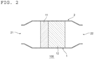
- the acid gas adsorption device 100 includes the acid gas adsorption part 1 including the first adsorption portion 11 and the second adsorption portion 12; and one case 2.
- the case 2 houses the acid gas adsorption part 1.
- the one case 2 houses the first adsorption portion 11 and the second adsorption portion 12 together.
- housing the first adsorption portion and the second adsorption portion together in one case enables a reduction in size of the acid gas adsorption device.
- facility cost can be kept low.
- the amount of capture of the acid gas per area can be increased.
- the case 2 has a tubular shape extending in the direction of passage of the fluid.
- An upstream end portion of the case 2 in the direction of passage of the fluid is formed as a first opening 21.
- a downstream end portion of the case 2 in the direction of passage of the fluid is formed as a second opening 22.
- the acid gas adsorption part 1 is arranged between the first opening 21 and the second opening 22 in an internal space of the case 2.
- the first adsorption portion 11 is arranged between the first opening 21 and the second adsorption portion 12.
- the second adsorption portion 12 is arranged on a side opposite to the first opening 21 with respect to the first adsorption portion 11.
- the fluid can pass through each of the first opening 21 and the second opening 22.
- the fluid containing the acid gas is supplied to the first adsorption portion 11 via the first opening 21.
- the fluid that has passed through the first adsorption portion 11 and the second adsorption portion 12 in the stated order is discharged from the second opening 22.
- the first adsorption portion 11 includes an upstream end surface 1a of the acid gas adsorption part 1 in the direction of passage of the fluid.
- the second adsorption portion 12 includes a downstream end surface 1b of the acid gas adsorption part 1 in the direction of passage of the fluid.
- the direction of passage of the fluid is typically orthogonal to each of the upstream end surface 1a and the downstream end surface 1b of the acid gas adsorption part 1.
- a dimension of the acid gas adsorption part 1 in the direction of passage of the fluid is not limited to any particular dimension as long as fan driving power is not increased due to a pressure loss, and is, for example, 0.5 m or more, preferably 0.6 m or more, and is, for example, 2.0 m or less, preferably 1.0 m or less.
- a dimension of the acid gas adsorption part 1 in a direction orthogonal to the direction of passage of the fluid is not limited to any particular dimension, and is, for example, 1.5 m or more, preferably 2.0 m or more, and is, for example, 4.0 m or less, preferably 3.0 m or less.
- a dimension ratio of each of the first adsorption portion 11 and the second adsorption portion 12 is, for example, from 10% to 90%, preferably from 20% to 80%, more preferably from 30% to 70%.
- a distance between the first opening 21 and the upstream end surface 1a of the first adsorption portion 11 in the direction of passage of the fluid is, for example, 1 cm or more, preferably 5 cm or more, more preferably 10 cm or more. Further, a distance between the downstream end surface 1b of the second adsorption portion 12 and the second opening 22 in the direction of passage of the fluid is, for example, 1 cm or more, preferably 5 cm or more, more preferably 10 cm or more.
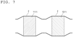
- the acid gas adsorption part 1 may be formed by integrally forming the first adsorption portion 11 and the second adsorption portion 12 as illustrated in FIG. 2 , or may be divided into the first adsorption portion 11 and the second adsorption portion 12 in the direction of passage of the fluid as illustrated in FIG. 1 .
- a dimension of the gap in the direction of passage of the fluid is, for example, 30% or less, preferably 10% or less with respect to the full length of the acid gas adsorption part in the direction of passage of the fluid (sum of the dimension of the first adsorption portion and the dimension of the second adsorption portion in the direction of passage of the fluid).
- the dimension of the gap is equal to or less than the upper limit described above, stagnation of the fluid between the first adsorption portion and the second adsorption portion can be suppressed. Hence, the fluid is allowed to smoothly flow from the first adsorption portion to the second adsorption portion.
- any appropriate values may be used for the dimensions of the first adsorption portion 11 and the second adsorption portion 12 in the direction of passage of the fluid in accordance with the acid gas adsorption materials used therefor, respectively.
- the dimension of the first adsorption portion 11 in the direction of passage of the fluid is longer than the dimension of the second adsorption portion 12.
- the dimension of the first adsorption portion 11 in the direction of passage of the fluid is, for example, 50% or more, preferably 60% or more, and is, for example, 90% or less, preferably 80% or less with respect to the full length of the acid gas adsorption part 1 (sum of the dimension of the first adsorption portion and the dimension of the second adsorption portion).
- the dimension of the second adsorption portion 12 in the direction of passage of the fluid is, for example, 10% or more, preferably 30% or more, and is, for example, 50% or less, preferably 40% or less with respect to the full length of the acid gas adsorption part 1.
- the improvement in acid gas adsorption efficiency can be stably achieved.
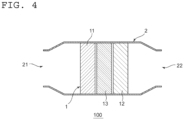
- the acid gas adsorption part 1 further includes a third adsorption portion 13 arranged between the first adsorption portion 11 and the second adsorption portion 12.
- the first adsorption portion, the second adsorption portion, and the third adsorption portion can be separately and smoothly produced as compared to a case in which the acid gas adsorption part is produced as one integral body.
- a gap may be defined between the first adsorption portion 11 or the second adsorption portion 12 and the third adsorption portion 13 in the direction of passage of the fluid. Ranges of a dimension of the gap between the first adsorption portion 11 or the second adsorption portion 12 and the third adsorption portion 13 are the same as the above-mentioned ranges of the dimension of the gap between the first adsorption portion 11 and the second adsorption portion 12.
- the third adsorption portion 13 may include the same acid gas adsorption material as that of the first adsorption portion 11 as illustrated in FIG. 3 , or may include a mixture of the acid gas adsorption material of the first adsorption portion 11 and the acid gas adsorption material of the second adsorption portion 12 as illustrated in FIG. 4 .
- the third adsorption portion 13 includes an acid gas adsorption material different from the acid gas adsorption material of the first adsorption portion 11 and the acid gas adsorption material of the second adsorption portion 12 (see FIG. 4 ).
- the third adsorption portion 13 preferably includes a third acid gas adsorption material.
- An adsorption force of the third acid gas adsorption material is larger than that of the first acid gas adsorption material and smaller than that of the second acid gas adsorption material.
- An adsorption capacity of the third acid gas adsorption material is smaller than that of the first acid gas adsorption material and larger than that of the second acid gas adsorption material.
- the first adsorption portion 11 is divided into four blocks in the direction (up-and-down direction on the drawing sheet) orthogonal to the direction of passage of the fluid.
- the number of division of the first adsorption portion in the direction orthogonal to the direction of passage of the fluid is not limited to the number described above.
- the first adsorption portion 11 may also be divided into a plurality of blocks in the direction (depth direction on the drawing sheet) orthogonal to the direction of passage of the fluid.
- the number of division of the first adsorption portion in the direction orthogonal to the direction of passage of the fluid is, for example, 2 or more and 300 or less.
- all the plurality of first blocks 11a may include the same first acid gas adsorption material, or some of the plurality of first blocks 11a may include a different first acid gas adsorption material.
- the second adsorption portion 12 is divided into a plurality of second blocks 12a in the direction orthogonal to the direction of passage of the fluid.
- the second adsorption portion 12 is formed of the plurality of second blocks 12a arranged in the direction orthogonal to the direction of passage of the fluid.
- the second blocks each being relatively small, are produced to form the second adsorption portion. Accordingly, the second adsorption portion can easily be produced.
- Ranges of the dimensions of the second block 12a are the same as the above-mentioned ranges of the dimensions of the first block 11a.
- Adjacent second blocks 12a among the plurality of second blocks 12a may define a gap therebetween or may be in contact with each other in the direction orthogonal to the direction of passage of the fluid.
- the second adsorption portion 12 is divided into four blocks in the direction (up-and-down direction on the drawing sheet) orthogonal to the direction of passage of the fluid.
- the number of division of the second adsorption portion in the direction orthogonal to the direction of passage of the fluid is not limited to the number described above.
- the second adsorption portion 12 may also be divided into a plurality of blocks in the direction (depth direction on the drawing sheet) orthogonal to the direction of passage of the fluid.
- the number of division of the second adsorption portion in the direction orthogonal to the direction of passage of the fluid is, for example, 2 or more and 300 or less, preferably is the same as the number of division of the first adsorption portion.
- all the plurality of second blocks 12a may include the same second acid gas adsorption material, or some of the plurality of second blocks 12a may include a different second acid gas adsorption material.
- the third adsorption portion 13 is divided into a plurality of third blocks 13a in the direction orthogonal to the direction of passage of the fluid.
- the third adsorption portion 13 is formed of the plurality of third blocks 13a arranged in the direction orthogonal to the direction of passage of the fluid.
- the third blocks each being relatively small, are produced to form the third adsorption portion. Accordingly, the third adsorption portion can easily be produced.
- Ranges of the dimensions of the third block 13a are the same as the above-mentioned ranges of the dimensions of the first block 11a.
- Adjacent third blocks 13a among the plurality of third blocks 13a may define a gap therebetween or may be in contact with each other in the direction orthogonal to the direction of passage of the fluid.
- the third adsorption portion 13 is divided into four blocks in the direction (up-and-down direction on the drawing sheet) orthogonal to the direction of passage of the fluid.
- the number of division of the third adsorption portion in the direction orthogonal to the direction of passage of the fluid is not limited to the number described above.
- the third adsorption portion 13 may also be divided into a plurality of blocks in the direction (depth direction on the drawing sheet) orthogonal to the direction of passage of the fluid.
- the number of division of the third adsorption portion in the direction orthogonal to the direction of passage of the fluid is, for example, 2 or more and 300 or less, preferably is the same as the number of division of the first adsorption portion.
- all the plurality of third blocks 13a may include the same acid gas adsorption material, or some of the plurality of third blocks 13a may include a different acid gas adsorption material.
- the third blocks 13a positioned in a central area and the third blocks 13a positioned in outer areas include acid gas adsorption materials different from each other. More specifically, in the third adsorption portion 13, the third blocks 13a positioned in the central area include the above-mentioned third acid gas adsorption material, and the third blocks 13a positioned in the outer areas include the above-mentioned second acid gas adsorption material.
- the acid gas adsorption part 1 can include the third adsorption portion to an n-th adsorption portion between the first adsorption portion 11 and the second adsorption portion 12.
- the n-th adsorption portion includes an n-th acid gas adsorption material.
- Each of the n-th adsorption portions may be divided into a plurality of n-th blocks in the direction orthogonal to the direction of passage of the fluid in the same manner as described above.
- the number "n" is, for example, 4 or more and 30 or less.
- an adsorption force of the acid gas adsorption material in the adsorption portion closer to the downstream side in the direction of passage of the fluid be larger.
- the acid gas adsorption part 1 includes at least the first adsorption portion 11 and the second adsorption portion 12. Further, the acid gas adsorption part 1 may include the third adsorption portion 13 to the n-th adsorption portion.
- the first to the n-th adsorption portions typically have the same configuration except for a kind of the acid gas adsorption material.
- the first adsorption portion 11 (integrally formed) illustrated in FIG. 1 and the first block 11a illustrated in FIG. 5 have the same configuration except for a difference in size. Thus, the configuration of the first block 11a illustrated in FIG. 5 is described in detail below.
- the first block 11a includes a plurality of adsorption material layers 71.
- Each of the plurality of adsorption material layers 71 includes a flexible fiber member 73 and a plurality of pellet-like adsorption materials 72.
- the plurality of pellet-like adsorption materials 72 are filled in the flexible fiber member 73 having a hollow shape (bag shape).
- the pellet-like adsorption material 72 serves as an acid gas adsorption material, and typically serves as a carbon dioxide adsorption material.
- Examples of a material for the pellet-like adsorption material 72 include a material modified with the above-mentioned acid gas adsorption material (the first acid gas adsorption material or the second acid gas adsorption material), preferably cellulose modified with the above-mentioned acid gas adsorption material (the first acid gas adsorption material or the second acid gas adsorption material), more preferably nanofibrillated cellulose modified with the above-mentioned acid gas adsorption material (the first acid gas adsorption material or the second acid gas adsorption material).
- a mean primary particle diameter of the pellet-like adsorption material 72 is, for example, 60 ⁇ m or more and 1,200 ⁇ m or less. Any appropriate value may be used as a filling ratio of the pellet-like adsorption materials 72 in the adsorption material layer 71.
- the acid gas adsorption device 1 of the illustrated example further includes a plurality of spacers 74.
- the spacer 74 is located between adjacent adsorption material layers 71 among the plurality of adsorption material layers 71. This configuration allows a distance between adjacent adsorption material layers among the adsorption material layers to be stably ensured.
- the plurality of adsorption material layers 71 and the plurality of spacers 74 are arranged in a substantially zig-zag pattern when viewed from a direction (depth direction on the drawing sheet of FIG. 1 ) orthogonal to the thickness direction of the adsorption material layers 71.
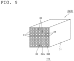
- the first block 11a typically includes a base material 3 and acid gas adsorption layers 4.
- the structure of the base material 3 is not particularly limited, and is, for example, a honeycomb-like structure, a filter structure such as a filtration cloth, or a pellet structure.
- the acid gas adsorption layer 4 is not particularly limited as long as the layer is arranged on the surface of any such base material 3.
- the base material 3 is a honeycomb-like base material 3a.
- the honeycomb-like base material 3a includes partition walls 32 that define a plurality of cells 33.
- a cell density in a cross section in the direction perpendicular to the lengthwise direction of the honeycomb-like base material may be appropriately set in accordance with purposes.
- the cell density may be, for example, from 4 cells/cm 2 to 320 cells/cm 2 . When the cell density falls within such range, the strength and effective geometric surface area (GSA) of the honeycomb-like base material can be sufficiently ensured.
- the honeycomb-like base material 3a typically includes: an outer wall 31; and a partition wall 32 positioned inside the outer wall 31.
- the outer wall 31 and the partition wall 32 are integrally formed.
- the outer wall 31 and the partition wall 32 may be separate bodies.
- the outer wall 31 has a rectangular cylindrical shape.
- the thickness of the outer wall 31 may be set to any appropriate thickness.
- the thickness of the outer wall 31 is, for example, from 0.1 mm to 10 mm.
- the partition wall 32 defines the plurality of cells 33. More specifically, the partition wall 32 has a first partition wall 32a and a second partition wall 32b perpendicular to each other, and the first partition wall 32a and the second partition wall 32b define the plurality of cells 33.
- the sectional shapes of the cells 33 are each a substantially quadrangular shape.
- the configuration of the partition wall is not limited to the partition wall 32 described above.
- the partition wall may have a first partition wall extending in a radial direction and a second partition wall extending in a circumferential direction, which define a plurality of cells.
- the thickness of the partition wall 32 may be appropriately set in accordance with the applications of the acid gas adsorption device.
- the thickness of the partition wall 32 is typically smaller than the thickness of the outer wall 31.
- the thickness of the partition wall 32 is, for example, from 0.03 mm to 0.6 mm.
- the thickness of the partition wall is measured, for example, through sectional observation with a scanning electron microscope (SEM). When the thickness of the partition wall falls within such range, the honeycomb-like base material can achieve sufficient mechanical strength, and can also achieve a sufficient opening area (total area of the cells in a cross section).
- the bulk density of the partition wall 32 may be appropriately set in accordance with purposes.
- the bulk density is, for example, 0.10 g/cm 3 or more, preferably 0.20 g/cm 3 or more, and is, for example, 0.60 g/cm 3 or less, preferably 0.50 g/cm 3 or less.
- the bulk density may be measured, for example, by mercury porosimetry.
- a material for forming the partition wall 32 is typically, for example, a ceramic.
- the ceramic include silicon carbide, a silicon-silicon carbide-based composite material, cordierite, mullite, alumina, silicon nitride, spinel, a silicon carbide-cordierite-based composite material, lithium aluminum silicate, and aluminum titanate.
- Those materials for forming the partition walls may be used alone or in combination thereof.
- cordierite, alumina, mullite, silicon carbide, a silicon-silicon carbide-based composite material, and silicon nitride are preferred, and silicon carbide and a silicon-silicon carbide-based composite material are more preferred.
- the acid gas adsorption layer 4 is formed on the surface of the partition wall 32.
- a flow passage 34 is formed in a portion (typically, a center portion) in a cross section of the cell 33 in which the acid gas adsorption layer 4 is not formed.
- the acid gas adsorption layer 4 may be formed on the entire inner surface of the partition wall 32 (specifically, so as to surround the flow passage 34) as in the illustrated example, or may be formed on part of the surface of the partition wall. When the acid gas adsorption layer 4 is formed on the entire inner surface of the partition wall 32, an improvement in acid gas (typically, CO 2 ) adsorption efficiency can be achieved.
- the fluid containing the acid gas is typically supplied to the cells 33 (more specifically, the flow passages 34 ) in an adsorption step described later.
- the content ratio of the acid gas adsorption material in the acid gas adsorption material layer is, for example, 30 mass% or more, preferably 50 mass% or more, and is, for example, 99 mass% or less.
- the content ratio of the porous carrier is, for example, 0.01 part by mass or more, preferably 0.3 part by mass or more, and is, for example, 0.7 part by mass or less, preferably 0.5 part by mass or less with respect to 1 part by mass of the acid gas adsorption material.
- the acid gas adsorption material can be more stably supported.
- the fluid containing the acid gas is supplied to the acid gas adsorption part 1 adjusted to a predetermined adsorption temperature.
- the fluid containing the acid gas first flows into the first adsorption portion 11 (more specifically, the flow passages 34 of the first blocks 11a).
- the first acid gas adsorption material of the first adsorption portion 11 adsorbs a relatively large volume of the acid gas from the fluid containing the acid gas (typically, CO 2 ) at a relatively high concentration.
- the fluid now having a decreased concentration of the acid gas flows into the second adsorption portion 12 (more specifically, the flow passages 34 of the second blocks 12a).
- the second acid gas adsorption material of the second adsorption portion 12 stably adsorbs the acid gas from the fluid containing the acid gas (typically, CO 2 ) at a relatively low concentration.
- the acid gas is efficiently adsorbed from the fluid supplied to the acid gas adsorption part.
- a temperature (adsorption temperature) of the acid gas adsorption part in the adsorption step is, for example, 0°C or more, preferably 10°C or more, and is, for example, 50°C or less, preferably 40°C or less. In one embodiment, the adsorption temperature is equal to an outside air temperature.
- An operation time period of the adsorption step (adsorption time) is, for example, 15 minutes or more, preferably 30 minutes or more, and is, for example, 3 hours or less, preferably 2 hours or less.
- the acid gas adsorption material can efficiently adsorb the acid gas.
- the acid gas adsorption part 1 is typically heated to a desorption temperature exceeding the adsorption temperature. More specifically, in the desorption step, after the temperature of the acid gas adsorption part 1 is raised to the adsorption temperature, the acid gas adsorption part 1 is maintained at the desorption temperature for predetermined desorption time. As a result, the acid gas, which has been adsorbed by the acid gas adsorption material (the first acid gas adsorption material and the second acid gas adsorption material) in the adsorption step, is desorbed from the acid gas adsorption material. Thus, the desorbed acid gas can be captured.
- the acid gas adsorption material the first acid gas adsorption material and the second acid gas adsorption material
- the desorbed gas in the desorption step, is supplied to the acid gas adsorption part 1 so as to pass through the first adsorption portion 11 and the second adsorption portion 12 in the stated order.
- the desorbed acid gas is captured together with the desorbed gas.
- the gas captured in the desorption step is sometimes referred to as "captured gas.”
- the desorbed gas is preferably a captured gas that has previously been captured by the acid gas adsorption device. The use of the captured gas as the desorbed gas enables achievement of an increase in concentration of the acid gas in the captured gas.
- the acid gas can also be captured without using the desorbed gas.
- the desorbed acid gas may be sucked and captured by a decompression pump. Further, the desorbed gas and the decompression pump can be used in combination.
- the temperature of the acid gas adsorption part in the desorption step is, for example, 70°C or more, preferably 80°C or more, and is, for example, 200°C or less, preferably 110°C or less.
- An operation time period of the desorption step is, for example, 1 minute or more, preferably 5 minutes or more, and is, for example, 1 hour or less, preferably 30 minutes or less.
- the acid gas can be efficiently captured.
- the adsorption step and the desorption step are preferably repeated in the order.
- the acid gas adsorption device can be used for separation and capture of an acid gas, and particularly, can be suitably used for a Carbon dioxide Capture, Utilization and Storage (CCUS) cycle.
- CCUS Carbon dioxide Capture, Utilization and Storage
Landscapes
- Chemical & Material Sciences (AREA)
- Engineering & Computer Science (AREA)
- Analytical Chemistry (AREA)
- General Chemical & Material Sciences (AREA)
- Oil, Petroleum & Natural Gas (AREA)
- Chemical Kinetics & Catalysis (AREA)
- Separation Of Gases By Adsorption (AREA)
- Treating Waste Gases (AREA)
Applications Claiming Priority (2)
| Application Number | Priority Date | Filing Date | Title |
|---|---|---|---|
| JP2022139533 | 2022-09-01 | ||
| PCT/JP2023/031206 WO2024048577A1 (ja) | 2022-09-01 | 2023-08-29 | 酸性ガス吸着装置 |
Publications (1)
| Publication Number | Publication Date |
|---|---|
| EP4582171A1 true EP4582171A1 (en) | 2025-07-09 |
Family
ID=90099596
Family Applications (1)
| Application Number | Title | Priority Date | Filing Date |
|---|---|---|---|
| EP23860339.3A Pending EP4582171A1 (en) | 2022-09-01 | 2023-08-29 | Acidic-gas adsorption device |
Country Status (7)
| Country | Link |
|---|---|
| US (1) | US20250186930A1 (https=) |
| EP (1) | EP4582171A1 (https=) |
| JP (1) | JPWO2024048577A1 (https=) |
| CN (1) | CN119730940A (https=) |
| AU (1) | AU2023334312B2 (https=) |
| TW (1) | TW202417104A (https=) |
| WO (1) | WO2024048577A1 (https=) |
Family Cites Families (12)
| Publication number | Priority date | Publication date | Assignee | Title |
|---|---|---|---|---|
| JPS5768163U (https=) * | 1980-10-14 | 1982-04-23 | ||
| JPH10263395A (ja) * | 1997-03-26 | 1998-10-06 | Nichias Corp | 有機溶剤ガス吸着素子 |
| JP2000157620A (ja) * | 1998-11-26 | 2000-06-13 | Hitachi Ltd | 脱臭装置 |
| JP3500354B2 (ja) * | 2000-09-29 | 2004-02-23 | 株式会社東芝 | 硫化物ガス吸収材および硫化物ガスの除去装置 |
| JP5846546B2 (ja) * | 2012-02-10 | 2016-01-20 | Jfeエンジニアリング株式会社 | 揮発性有機化合物を含有する排ガスの処理装置および処理方法 |
| KR102360223B1 (ko) * | 2012-05-07 | 2022-02-09 | 도널드선 컴파니 인코포레이티드 | 실록산 오염물질 제거를 위한 물질, 방법 및 장치 |
| NO2986357T3 (https=) | 2013-04-18 | 2018-07-14 | ||
| KR102472112B1 (ko) * | 2014-10-24 | 2022-11-28 | 리써치 트라이앵글 인스티튜트 | 가스 스트림으로부터 산 가스를 제거하기 위한 통합 시스템 및 방법 |
| JP6805770B2 (ja) * | 2016-12-05 | 2020-12-23 | 株式会社Ihi | 気体濃縮装置 |
| JP2022105394A (ja) * | 2021-01-04 | 2022-07-14 | 大陽日酸株式会社 | 吸着塔 |
| JP2023069542A (ja) * | 2021-11-05 | 2023-05-18 | 大阪ガスケミカル株式会社 | キャニスタ |
| JP2023069543A (ja) * | 2021-11-05 | 2023-05-18 | 大阪ガスケミカル株式会社 | キャニスタ |
-
2023
- 2023-08-29 CN CN202380056425.1A patent/CN119730940A/zh active Pending
- 2023-08-29 EP EP23860339.3A patent/EP4582171A1/en active Pending
- 2023-08-29 WO PCT/JP2023/031206 patent/WO2024048577A1/ja not_active Ceased
- 2023-08-29 JP JP2024544281A patent/JPWO2024048577A1/ja active Pending
- 2023-08-29 AU AU2023334312A patent/AU2023334312B2/en active Active
- 2023-08-31 TW TW112132938A patent/TW202417104A/zh unknown
-
2025
- 2025-02-24 US US19/060,836 patent/US20250186930A1/en active Pending
Also Published As
| Publication number | Publication date |
|---|---|
| US20250186930A1 (en) | 2025-06-12 |
| TW202417104A (zh) | 2024-05-01 |
| AU2023334312A1 (en) | 2025-03-13 |
| WO2024048577A1 (ja) | 2024-03-07 |
| AU2023334312B2 (en) | 2026-04-02 |
| JPWO2024048577A1 (https=) | 2024-03-07 |
| CN119730940A (zh) | 2025-03-28 |
Similar Documents
| Publication | Publication Date | Title |
|---|---|---|
| ES2294228T3 (es) | Contactadores de paso paralelo con material laminar adsorbente. | |
| US20250229213A1 (en) | Acid gas adsorption device | |
| US20250242292A1 (en) | Acid gas capture system | |
| EP3593884B1 (en) | Honeycomb filter | |
| US20250242289A1 (en) | Method of capturing an acid gas | |
| EP4582171A1 (en) | Acidic-gas adsorption device | |
| US20250186931A1 (en) | Acid gas adsorption device | |
| WO2024048567A1 (ja) | 酸性ガスの回収方法 | |
| US20260001027A1 (en) | Acid gas capture system and acid gas capture method | |
| US20260001026A1 (en) | Acid gas capture system and acid gas capture method | |
| AU2024368117A1 (en) | Acidic gas adsorption device | |
| WO2025088956A1 (ja) | 酸性ガス吸着装置 | |
| US20260091341A1 (en) | Acid gas adsorption device | |
| TWI922928B (zh) | 酸性氣體回收系統及酸性氣體之回收方法 | |
| TWI916798B (zh) | 酸性氣體回收系統及酸性氣體之回收方法 |
Legal Events
| Date | Code | Title | Description |
|---|---|---|---|
| STAA | Information on the status of an ep patent application or granted ep patent |
Free format text: STATUS: THE INTERNATIONAL PUBLICATION HAS BEEN MADE |
|
| PUAI | Public reference made under article 153(3) epc to a published international application that has entered the european phase |
Free format text: ORIGINAL CODE: 0009012 |
|
| STAA | Information on the status of an ep patent application or granted ep patent |
Free format text: STATUS: REQUEST FOR EXAMINATION WAS MADE |
|
| 17P | Request for examination filed |
Effective date: 20250401 |
|
| AK | Designated contracting states |
Kind code of ref document: A1 Designated state(s): AL AT BE BG CH CY CZ DE DK EE ES FI FR GB GR HR HU IE IS IT LI LT LU LV MC ME MK MT NL NO PL PT RO RS SE SI SK SM TR |
|
| DAV | Request for validation of the european patent (deleted) | ||
| DAX | Request for extension of the european patent (deleted) |