EP4582169A1 - Acidic gas adsorption device - Google Patents
Acidic gas adsorption device Download PDFInfo
- Publication number
- EP4582169A1 EP4582169A1 EP23860341.9A EP23860341A EP4582169A1 EP 4582169 A1 EP4582169 A1 EP 4582169A1 EP 23860341 A EP23860341 A EP 23860341A EP 4582169 A1 EP4582169 A1 EP 4582169A1
- Authority
- EP
- European Patent Office
- Prior art keywords
- adsorption
- acid gas
- gas
- passage
- opening
- Prior art date
- Legal status (The legal status is an assumption and is not a legal conclusion. Google has not performed a legal analysis and makes no representation as to the accuracy of the status listed.)
- Pending
Links
Images



Classifications
-
- B—PERFORMING OPERATIONS; TRANSPORTING
- B01—PHYSICAL OR CHEMICAL PROCESSES OR APPARATUS IN GENERAL
- B01D—SEPARATION
- B01D53/00—Separation of gases or vapours; Recovering vapours of volatile solvents from gases; Chemical or biological purification of waste gases, e.g. engine exhaust gases, smoke, fumes, flue gases, aerosols
- B01D53/02—Separation of gases or vapours; Recovering vapours of volatile solvents from gases; Chemical or biological purification of waste gases, e.g. engine exhaust gases, smoke, fumes, flue gases, aerosols by adsorption, e.g. preparative gas chromatography
- B01D53/04—Separation of gases or vapours; Recovering vapours of volatile solvents from gases; Chemical or biological purification of waste gases, e.g. engine exhaust gases, smoke, fumes, flue gases, aerosols by adsorption, e.g. preparative gas chromatography with stationary adsorbents
-
- B—PERFORMING OPERATIONS; TRANSPORTING
- B01—PHYSICAL OR CHEMICAL PROCESSES OR APPARATUS IN GENERAL
- B01D—SEPARATION
- B01D53/00—Separation of gases or vapours; Recovering vapours of volatile solvents from gases; Chemical or biological purification of waste gases, e.g. engine exhaust gases, smoke, fumes, flue gases, aerosols
- B01D53/02—Separation of gases or vapours; Recovering vapours of volatile solvents from gases; Chemical or biological purification of waste gases, e.g. engine exhaust gases, smoke, fumes, flue gases, aerosols by adsorption, e.g. preparative gas chromatography
- B01D53/04—Separation of gases or vapours; Recovering vapours of volatile solvents from gases; Chemical or biological purification of waste gases, e.g. engine exhaust gases, smoke, fumes, flue gases, aerosols by adsorption, e.g. preparative gas chromatography with stationary adsorbents
- B01D53/0407—Constructional details of adsorbing systems
- B01D53/0446—Means for feeding or distributing gases
-
- B—PERFORMING OPERATIONS; TRANSPORTING
- B01—PHYSICAL OR CHEMICAL PROCESSES OR APPARATUS IN GENERAL
- B01D—SEPARATION
- B01D2253/00—Adsorbents used in seperation treatment of gases and vapours
- B01D2253/10—Inorganic adsorbents
- B01D2253/102—Carbon
-
- B—PERFORMING OPERATIONS; TRANSPORTING
- B01—PHYSICAL OR CHEMICAL PROCESSES OR APPARATUS IN GENERAL
- B01D—SEPARATION
- B01D2253/00—Adsorbents used in seperation treatment of gases and vapours
- B01D2253/30—Physical properties of adsorbents
- B01D2253/34—Specific shapes
- B01D2253/342—Monoliths
- B01D2253/3425—Honeycomb shape
-
- B—PERFORMING OPERATIONS; TRANSPORTING
- B01—PHYSICAL OR CHEMICAL PROCESSES OR APPARATUS IN GENERAL
- B01D—SEPARATION
- B01D2257/00—Components to be removed
- B01D2257/20—Halogens or halogen compounds
- B01D2257/204—Inorganic halogen compounds
- B01D2257/2045—Hydrochloric acid
-
- B—PERFORMING OPERATIONS; TRANSPORTING
- B01—PHYSICAL OR CHEMICAL PROCESSES OR APPARATUS IN GENERAL
- B01D—SEPARATION
- B01D2257/00—Components to be removed
- B01D2257/30—Sulfur compounds
- B01D2257/302—Sulfur oxides
-
- B—PERFORMING OPERATIONS; TRANSPORTING
- B01—PHYSICAL OR CHEMICAL PROCESSES OR APPARATUS IN GENERAL
- B01D—SEPARATION
- B01D2257/00—Components to be removed
- B01D2257/30—Sulfur compounds
- B01D2257/304—Hydrogen sulfide
-
- B—PERFORMING OPERATIONS; TRANSPORTING
- B01—PHYSICAL OR CHEMICAL PROCESSES OR APPARATUS IN GENERAL
- B01D—SEPARATION
- B01D2257/00—Components to be removed
- B01D2257/30—Sulfur compounds
- B01D2257/306—Organic sulfur compounds, e.g. mercaptans
-
- B—PERFORMING OPERATIONS; TRANSPORTING
- B01—PHYSICAL OR CHEMICAL PROCESSES OR APPARATUS IN GENERAL
- B01D—SEPARATION
- B01D2257/00—Components to be removed
- B01D2257/40—Nitrogen compounds
- B01D2257/404—Nitrogen oxides other than dinitrogen oxide
-
- B—PERFORMING OPERATIONS; TRANSPORTING
- B01—PHYSICAL OR CHEMICAL PROCESSES OR APPARATUS IN GENERAL
- B01D—SEPARATION
- B01D2257/00—Components to be removed
- B01D2257/50—Carbon oxides
- B01D2257/504—Carbon dioxide
-
- B—PERFORMING OPERATIONS; TRANSPORTING
- B01—PHYSICAL OR CHEMICAL PROCESSES OR APPARATUS IN GENERAL
- B01D—SEPARATION
- B01D2258/00—Sources of waste gases
- B01D2258/06—Polluted air
-
- B—PERFORMING OPERATIONS; TRANSPORTING
- B01—PHYSICAL OR CHEMICAL PROCESSES OR APPARATUS IN GENERAL
- B01D—SEPARATION
- B01D2259/00—Type of treatment
- B01D2259/40—Further details for adsorption processes and devices
- B01D2259/40083—Regeneration of adsorbents in processes other than pressure or temperature swing adsorption
- B01D2259/40088—Regeneration of adsorbents in processes other than pressure or temperature swing adsorption by heating
- B01D2259/4009—Regeneration of adsorbents in processes other than pressure or temperature swing adsorption by heating using hot gas
-
- B—PERFORMING OPERATIONS; TRANSPORTING
- B01—PHYSICAL OR CHEMICAL PROCESSES OR APPARATUS IN GENERAL
- B01D—SEPARATION
- B01D53/00—Separation of gases or vapours; Recovering vapours of volatile solvents from gases; Chemical or biological purification of waste gases, e.g. engine exhaust gases, smoke, fumes, flue gases, aerosols
- B01D53/02—Separation of gases or vapours; Recovering vapours of volatile solvents from gases; Chemical or biological purification of waste gases, e.g. engine exhaust gases, smoke, fumes, flue gases, aerosols by adsorption, e.g. preparative gas chromatography
- B01D53/04—Separation of gases or vapours; Recovering vapours of volatile solvents from gases; Chemical or biological purification of waste gases, e.g. engine exhaust gases, smoke, fumes, flue gases, aerosols by adsorption, e.g. preparative gas chromatography with stationary adsorbents
- B01D53/0407—Constructional details of adsorbing systems
-
- Y—GENERAL TAGGING OF NEW TECHNOLOGICAL DEVELOPMENTS; GENERAL TAGGING OF CROSS-SECTIONAL TECHNOLOGIES SPANNING OVER SEVERAL SECTIONS OF THE IPC; TECHNICAL SUBJECTS COVERED BY FORMER USPC CROSS-REFERENCE ART COLLECTIONS [XRACs] AND DIGESTS
- Y02—TECHNOLOGIES OR APPLICATIONS FOR MITIGATION OR ADAPTATION AGAINST CLIMATE CHANGE
- Y02C—CAPTURE, STORAGE, SEQUESTRATION OR DISPOSAL OF GREENHOUSE GASES [GHG]
- Y02C20/00—Capture or disposal of greenhouse gases
- Y02C20/40—Capture or disposal of greenhouse gases of CO2
Definitions
- the present invention relates to an acid gas adsorption device.
- a temperature of the desorption gas decreases as the desorption gas flows downstream.
- a temperature distribution may occur in the carbon dioxide adsorption part due to non-uniformity in flow rate of the desorption gas in the carbon dioxide adsorption part and a decrease in temperature of the desorption gas.
- the temperature of the carbon dioxide adsorption part locally becomes less than the desorption temperature, and thus there arises a problem in that CO 2 cannot be sufficiently desorbed from the carbon dioxide adsorption material.
- the acid gas adsorption device 100 further include a second on-off valve 8.
- the second on-off valve 8 is housed in the case 6, and is capable of opening and closing the internal space of the case 6.
- the second on-off valve 8 is arranged on a downstream side of the second adsorption portion 2 in the direction of passage of the target gas to be treated.
- Examples of the second on-off valve 8 include a ball valve, a gate valve, and a butterfly valve. In the illustrated example, the second on-off valve 8 is a butterfly valve.
- a third desorption gas flow passage 13 communicating with the second flow passages 94b is defined between the second adsorption portion 2 and the second on-off valve 8 in the direction of passage of the target gas to be treated.
- the first desorption gas flow passage and the third desorption gas flow passage allow the desorption gas to flow smoothly and uniformly through the entirety of the second adsorption portion.
- the acid gas can be stably desorbed from the acid gas adsorption material in the second adsorption portion.
- a part of the internal space of the case 6, in which the second on-off valve 8 is arranged is formed as a second opening and closing port 80 to be opened and closed by the second on-off valve 8.
- An opening area of the second opening and closing port 80 is typically larger than the opening area of each of the first opening 61 and the second opening 62.
- the opening area of the second opening and closing port 80 is, for example, 8 to 12 times larger than the opening area of the first opening 61.
- the opening area of the second opening and closing port 80 may be the same as the opening area of the outflow port 65, or may be different from the opening area of the outflow port 65. In the illustrated example, the opening area of the second opening and closing port 80 is larger than the opening area of the outflow port 65. As a result, the distribution of flow of the desorption gas can be maintained uniform in the desorption step while a pressure loss in the adsorption step is kept low.
- the opening area of the second opening and closing port 80 is an area of a portion surrounded by the side wall of the case 6 on a cross section of the case 6, which is taken at the position of the second on-off valve 8 in the direction orthogonal to the axial direction (direction of passage of the target gas to be treated) of the case 6.
- the third desorption gas flow passage 13 is positioned on a side opposite to the first desorption gas flow passage 11 with respect to the second adsorption portion 2.
- the third desorption gas flow passage 13 extends in the direction orthogonal to the direction of passage of the target gas to be treated, and communicates with all of the plurality of second flow passages 94b.
- a dimension of the third desorption gas flow passage 13 in the direction of passage of the target gas to be treated is a distance between the second adsorption portion 2 and the second on-off valve 8 being in the closed state, and is a width of the third desorption gas flow passage 13 when viewed from the direction (depth direction on the drawing sheet of FIG. 1 ) orthogonal to the direction of passage of the target gas to be treated.
- the ranges of the maximum dimension of the third desorption gas flow passage 13 in the direction of passage of the target gas to be treated are the same as the above-mentioned ranges of the maximum dimension of the second desorption gas flow passage 12.
- the maximum dimension of the third desorption gas flow passage 13 falls within the above-mentioned ranges, smooth passage of the desorption gas can be achieved in the desorption step described later.
- the pressure loss in the second adsorption portion 2 is larger than a pressure loss in the third desorption gas flow passage 13.
- a third opening 63 communicating with the third desorption gas flow passage 13 is formed in the side wall of the case 6.
- the case 6 further has the third opening 63.
- a direction in which the third opening 63 extends may be parallel to a direction in which the third desorption gas flow passage 13 extends, or may be inclined so as to intersect with the direction in which the third desorption gas flow passage 13 extends.
- a third valve 18 is provided at the third opening 63.
- a capture unit (not shown) for capturing the desorption gas containing the acid gas desorbed from the acid gas adsorption material is connected to the third opening 63 through intermediation of the third valve 18.
- An opening area of the third opening 63 may be the same as the opening area of the second opening 62, or may be different from the opening area of the second opening 62. In the illustrated example, the opening area of the first opening 61, the opening area of the second opening 62, and the opening area of the third opening 63 are the same. The opening area of the third opening 63 is typically smaller than the opening area of the second opening and closing port 80.
- the acid gas adsorption device 100 may include a duct communicating with the third desorption gas flow passage 13 in place of the third opening 63.
- the first adsorption portion 1 is divided into a plurality of first blocks 1a in the direction orthogonal to the direction of passage of the target gas to be treated.
- the first adsorption portion 1 is formed of the plurality of first blocks 1a arranged in the direction orthogonal to the direction of passage of the target gas to be treated.
- the first blocks each being relatively small, are produced to form the first adsorption portion. Accordingly, as compared to a case in which the first adsorption portion is produced as one body, the first adsorption portion can easily be produced.
- Adjacent first blocks 1a among the plurality of first blocks 1a may define a gap therebetween or may be in contact with each other in the direction orthogonal to the direction of passage of the target gas to be treated. Further, although not shown, a plate-like member may be provided between adjacent first blocks 1a .
- the first adsorption portion 1 is divided into four blocks in the up-and-down direction on the drawing sheet (direction orthogonal to the direction of passage of the target gas to be treated).
- the first adsorption portion 1 may be divided into a plurality of blocks in the depth direction on the drawing sheet (direction orthogonal to the direction of passage of the target gas to be treated).
- the second adsorption portion 2 is divided into a plurality of second blocks 2a in the direction orthogonal to the direction of passage of the target gas to be treated.
- the second adsorption portion 2 is formed of the plurality of second blocks 2a arranged in the direction orthogonal to the direction of passage of the target gas to be treated.
- the second blocks each being relatively small, are produced to form the second adsorption portion. Accordingly, the second adsorption portion can easily be produced. Accordingly, as compared to a case in which the second adsorption portion is produced as one body, the second adsorption portion can easily be produced.
- Adjacent second blocks 2a among the plurality of second blocks 2a may define a gap therebetween or may be in contact with each other in the direction orthogonal to the direction of passage of the target gas to be treated. Further, although not shown, a plate-like member may be provided between adjacent second blocks 2a.
- the second adsorption portion 2 is divided into four blocks in the up-and-down direction on the drawing sheet (direction orthogonal to the direction of passage of the target gas to be treated).
- the second adsorption portion 2 may be divided into a plurality of blocks in the depth direction on the drawing sheet (direction orthogonal to the direction of passage of the target gas to be treated).
- the number of second blocks 2a is, for example, 2 or more, preferably 3 or more, more preferably 5 or more, and is, for example, 300 or less.
- Examples of the acid gas to be adsorbed by the acid gas adsorption part 10 include carbon dioxide (CO 2 ), hydrogen sulfide, sulfur dioxide, nitrogen dioxide, dimethyl sulfide (DMS), and hydrogen chloride.
- the acid gas is carbon dioxide (CO 2 )
- the fluid is a CO 2 -containing gas.
- the CO 2 -containing gas may contain nitrogen in addition to CO 2 .
- the CO 2 -containing gas is typically air (atmosphere).
- a concentration of CO 2 in the CO 2 -containing gas before being supplied to the acid gas adsorption device is, for example, 100 ppm (on a volume basis) or more and 2 vol% or less.
- the acid gas adsorption part 10 includes the first adsorption portion 1 and the second adsorption portion 2.
- the first adsorption portion 1 and the second adsorption portion 2 have the same configuration.
- the first adsorption portion 1 (integrally formed) illustrated in FIG. 1 and the first block 1a illustrated in FIG. 2 have the same configuration except for a difference in size.
- the configuration of the first block 1a illustrated in FIG. 2 is described in detail below.
- the first block 1a includes the honeycomb-like base material 9 and the acid gas adsorption layers 5 as described above.
- the honeycomb-like base material 9 typically includes partition walls 92 that define a plurality of cells 93.
- the cells 93 each extend from a first end surface E1 (inflow end surface) of the honeycomb-like base material 9 to a second end surface E2 (outflow end surface) thereof in the lengthwise direction (axial direction) of the honeycomb-like base material 3a (see FIG. 4 ).
- the cells 93 each have any appropriate shape in a cross section in a direction perpendicular to the lengthwise direction of the honeycomb-like base material 9.
- the sectional shapes of the cells are each, for example, a triangle, a quadrangle, a pentagon, a hexagon, a higher polygon, a circle, or an ellipse.
- the sectional shapes and sizes of the cells may be all the same, or may be at least partly different. Of such sectional shapes of the cells, for example, a hexagon or a quadrangle is preferred, and a square, a rectangle, or a hexagon is more preferred.
- a cell density in a cross section in the direction perpendicular to the lengthwise direction of the honeycomb-like base material may be appropriately set in accordance with purposes.
- the cell density may be, for example, from 4 cells/cm 2 to 320 cells/cm 2 . When the cell density falls within such range, the strength and effective geometric surface area (GSA) of the honeycomb-like base material can be sufficiently ensured.
- the honeycomb-like base material 9 has any appropriate shape (overall shape).
- the shape of the honeycomb-like base material is, for example, a cylinder with a circle as its bottom, an elliptic cylinder with an ellipse as its bottom, a prismatic column with a polygon as its bottom, or a column with an indefinite shape as its bottom.
- the honeycomb-like base material 9 of the illustrated example has a prismatic columnar shape.
- the outer diameter and length of the honeycomb-like base material may be appropriately set in accordance with purposes.
- the honeycomb-like base material may have a hollow region in a center portion thereof in the cross section in the direction perpendicular to the lengthwise direction, though the hollow region is not shown.
- the honeycomb-like base material 9 typically includes: an outer wall 91; and a partition wall 92 positioned inside the outer wall 91.
- the outer wall 91 and the partition wall 92 are integrally formed.
- the outer wall 91 and the partition wall 92 may be separate bodies.
- the outer wall 91 has a rectangular cylindrical shape.
- the thickness of the outer wall 91 may be set to any appropriate thickness.
- the thickness of the outer wall 91 is, for example, from 0.1 mm to 10 mm.
- the partition wall 92 defines the plurality of cells 93. More specifically, the partition wall 92 has a first partition wall 92a and a second partition wall 92b perpendicular to each other, and the first partition wall 92a and the second partition wall 92b define the plurality of cells 93.
- the sectional shapes of the cells 93 are each a substantially quadrangular shape.
- the configuration of the partition wall is not limited to the partition wall 92 described above.
- the partition wall may have a first partition wall extending in a radial direction and a second partition wall extending in a circumferential direction, which define a plurality of cells.
- the porosity of the partition wall 92 may be appropriately set in accordance with purposes.
- the porosity of the partition wall 92 is, for example, 15% or more, preferably 20% or more, and is, for example, 70% or less, preferably 45% or less.
- the porosity may be measured, for example, by mercury porosimetry.
- the bulk density of the partition wall 92 may be appropriately set in accordance with purposes.
- the bulk density is, for example, 0.10 g/cm 3 or more, preferably 0.20 g/cm 3 or more, and is, for example, 0.60 g/cm 3 or less, preferably 0.50 g/cm 3 or less.
- the bulk density may be measured, for example, by mercury porosimetry.
- a material for forming the partition wall 92 is typically, for example, a ceramic.
- the ceramic include silicon carbide, a silicon-silicon carbide-based composite material, cordierite, mullite, alumina, silicon nitride, spinel, a silicon carbide-cordierite-based composite material, lithium aluminum silicate, and aluminum titanate.
- Those materials for forming the partition walls may be used alone or in combination thereof.
- cordierite, alumina, mullite, silicon carbide, a silicon-silicon carbide-based composite material, and silicon nitride are preferred, and silicon carbide and a silicon-silicon carbide-based composite material are more preferred.
- honeycomb-like base material 9 is typically produced by the following method. First, a binder and water or an organic solvent are added to material powder including ceramic powder described above as required. The resultant mixture is kneaded to provide a body, and the body is molded (typically extruded) into a desired shape. After that, the body is dried, and is fired as required. Thus, the honeycomb-like base material 9 is produced. When the firing is adopted, the body is fired at, for example, from 1,200°C to 1,500°C. A firing time period is, for example, 1 hour or more and 20 hours or less.
- the flow passage 94 extends from the first end surface E1 (inflow end surface) to the second end surface E2 (outflow end surface) as with the cells 93.
- Examples of the sectional shape of the flow passage 94 include the same sectional shapes as those of the cells 93 described above. Of those, for example, a hexagon or a quadrangle is preferred, and a square, a rectangle, or a hexagon is more preferred.
- the sectional shapes and sizes of the flow passage 94 may be all the same, or may be at least partly different.
- the target gas to be treated containing the acid gas is supplied to the cells 93 (more specifically, the flow passages 94 ) in the adsorption step described later, and the desorption gas flows in the desorption step described later.
- the acid gas adsorption layer 5 includes the acid gas adsorption material in accordance with the acid gas to be adsorbed.
- the acid gas is CO 2
- the acid gas adsorption material is a carbon dioxide adsorption material.
- any appropriate compound capable of adsorbing and desorbing CO 2 may be adopted as the carbon dioxide adsorption material.
- the carbon dioxide adsorption material include: nitrogen-containing compounds described later; alkali compounds, such as sodium hydroxide and potassium hydroxide; carbonate salts, such as calcium carbonate and potassium carbonate; hydrogen carbonate salts, such as calcium hydrogen carbonate and potassium hydrogen carbonate; metal organic flameworks (MOF), such as MOF-74, MOF-200, and MOF-210; zeolite; activated carbon; nitrogen-doped carbon; and ionic liquids.
- the carbon dioxide adsorption materials may be used alone or in combination thereof.
- a nitrogen-containing compound and an ionic liquid are preferred. More specific examples of the nitrogen-containing compound include: primary amines, such as monoethanolamine and polyvinylamine; secondary amines, such as diethanolamine, a cyclic amine, and N-(3-aminopropyl)diethanolamine; tertiary amines, such as methyldiethylamine and triethanolamine; ethylene amine compounds such as tetraethylenepentamine; amino silane coupling agents, such as aminopropyltrimethoxysilane, 3-aminopropyltriethoxysilane, N-(2-aminoethyl)-3-aminopropyltrimethoxysilane, and polyethyleneimine-trimethoxysilane; imine compounds, such as ethyleneimine, a linear polyethyleneimine, a branched polyethyleneimine having a primary amino group to tertiary amino group; piperazine compounds such
- nitrogen-containing compounds methyldiethylamine, monoethanolamine, a cyclic amine, diethanolamine, tetraethylenepentamine, ethyleneimine, a linear polyethyleneimine, a branched polyethyleneimine, and an organic/inorganic compound having imparted thereto an amino group as a substituent are preferred.
- the ionic liquid is a "salt" of a liquid formed only of an ion (an anion or a cation), and is in a liquid state under normal temperature and normal pressure (23°C, 0.1 MPa).
- a cation of the ionic liquid include: an ammonium-based ion, such as an imidazolium salt or a pyridinium salt; a phosphonium-based ion; a sulfonium salt; and an inorganic ion.
- anion of the ionic liquid examples include: a halogen-based ion, such as a bromide ion or a triflate ion; a boron-based ion such as a tetraphenylborate ion; a phosphorus-based ion such as a hexafluorophosphate ion; and a sulfur-based ion such as an alkyl sulfonate ion.
- a halogen-based ion such as a bromide ion or a triflate ion
- a boron-based ion such as a tetraphenylborate ion
- a phosphorus-based ion such as a hexafluorophosphate ion
- sulfur-based ion such as an alkyl sulfonate ion.
- the ionic liquid is used, more preferably, in combination with a carbon dioxide adsorption material other than the ionic liquid (hereinafter referred to as "another carbon dioxide adsorption material").
- the ionic liquid coats another carbon dioxide adsorption material (for example, a nitrogen-containing compound).
- a carbon dioxide adsorption material for example, a nitrogen-containing compound.
- the content ratio of the ionic liquid is, for example, 0.000001 part by mass or more, preferably 0.00001 part by mass or more, and is, for example, 0.1 part by mass or less, preferably 0.05 part by mass or less with respect to 1 part by mass of the other carbon dioxide adsorption material.
- the content ratio of the ionic liquid falls within the above-mentioned ranges, an improvement in performance of the carbon dioxide adsorption material and an increase in lifetime thereof can be stably achieved.
- the acid gas adsorption material layer 5 includes a porous carrier in addition to the above-mentioned acid gas adsorption material.
- the acid gas adsorption material is typically supported by the porous carrier to face the flow passage.
- the escape of the acid gas adsorption material from the acid gas adsorption material layer can be prevented in the adsorption step and/or the desorption step.
- the porous carrier may form mesopores in the acid gas adsorption material layer.
- the porous carrier include: metal organic frameworks (MOF), such as MOF-74, MOF-200, and MOF-210; activated carbon; nitrogen-doped carbon; mesoporous silica; mesoporous alumina; zeolite; a carbon nanotube; and a fluorinated resin such as polyvinylidene fluoride (PVDF).
- MOF metal organic frameworks
- activated carbon, PVDF, zeolite, mesoporous silica, and mesoporous alumina are preferred.
- Those porous carriers may be used alone or in combination thereof.
- a material different from that of the acid gas absorption material is preferably adopted for the porous carrier.
- the BET specific surface area of the porous carrier is, for example, 50 m 2 /g or more, preferably 500 m 2 /g or more.
- the surface area of the porous carrier is equal to or more than the above-mentioned lower limits, the acid gas adsorption material can be stably supported, and hence an improvement in acid gas adsorption efficiency can be achieved.
- the upper limit of the BET specific surface area of the porous carrier is typically 2,000 m 2 /g or less.
- the content ratio of the total of the acid gas adsorption material and the porous carrier in the acid gas adsorption material layer is, for example, 30 mass% or more, preferably 50 mass% or more, and is, for example, 100 mass% or less, preferably 99 mass% or less.
- the content ratio of the acid gas adsorption material in the acid gas adsorption material layer is, for example, 30 mass% or more, preferably 50 mass% or more, and is, for example, 99 mass% or less.
- the content ratio of the porous carrier is, for example, 0.01 part by mass or more, preferably 0.3 part by mass or more, and is, for example, 0.7 part by mass or less, preferably 0.5 part by mass or less with respect to 1 part by mass of the acid gas adsorption material.
- the acid gas adsorption material can be more stably supported.
- the acid gas adsorption material layer may be formed only of the acid gas adsorption material.
- the acid gas adsorption material is directly supported by the partition wall 92 to face the flow passage.
- the content ratio of the acid gas adsorption material in the acid gas adsorption material layer is typically 95.0 mass% or more and 100 mass% or less.
- excellent acid gas adsorption efficiency can be stably ensured.
- Such an acid gas adsorption material layer is typically produced by the following method.
- a solution of the acid gas adsorption material is prepared by dissolving the above-mentioned acid gas adsorption material in a solvent. Further, the above-mentioned porous carrier is added to the solvent as required. The order of addition of the acid gas adsorption material and the porous carrier is not limited to any particular order.
- the solution of the acid gas adsorption material is applied onto the base material (specifically, the partition walls), and the coating film is then dried, and is sintered as required. Thus, the acid gas adsorption material layer is formed.
- the configuration of the acid gas adsorption part (the first adsorption portion and the second adsorption portion) is not limited to that described above.
- the method of capturing an acid gas typically includes the adsorption step and the desorption step in the stated order.
- the first on-off valve 7 and the second on-off valve 8 are each brought into a closed state, and the acid gas adsorption part 10 (the first adsorption portion 1 and the second adsorption portion 2 ) is heated to a desorption temperature higher than the adsorption temperature. More specifically, after the temperature of each of the first adsorption portion 1 and the second adsorption portion 2 is raised to the desorption temperature, the first adsorption portion 1 and the second adsorption portion 2 are maintained at the desorption temperature for predetermined desorption time. As a result, the acid gas adsorbed by the acid gas adsorption material in the adsorption step is desorbed from the acid gas adsorption material.
- the acid gas desorbed from the acid gas adsorption material of the second adsorption portion 2 flows out into the third desorption gas flow passage 13 together with the desorption gas passing through the second flow passages 94b, and then is captured via the third opening 63 of the case 6.
- the gas captured in the desorption step is sometimes referred to as "captured gas”.
- the desorption gas is preferably a captured gas that has previously been captured by the acid gas adsorption device.
- the use of the captured gas as the desorption gas enables achievement of an increase in concentration of the acid gas in the captured gas.
- the captured gas can also be sucked by using, for example, the desorption gas and a decompression pump in combination.
- Desorption gas flow passages may be defined between adjacent n-th adsorption portions 3 among the plurality of n-th adsorption portions 3 and between the n-th adsorption portion 3 positioned on the most downstream side and the second on-off valve 8 being in the closed state.
- the n-th adsorption portion 3 has the same configuration as that of the first adsorption portion, and hence a detailed description thereof is omitted.
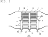
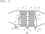
- the acid gas adsorption device 100 includes a third adsorption portion 31 and a fourth adsorption portion 32 in addition to the first adsorption portion 1 and the second adsorption portion 2.
- the third adsorption portion 31 is arranged on the downstream side of the second adsorption portion 2 in the direction of passage of the target gas to be treated so as to be spaced apart therefrom.
- a third desorption gas flow passage 13 is defined between the second adsorption portion 2 and the third adsorption portion 31 in the direction of passage of the target gas to be treated.
- the fourth adsorption portion 32 is arranged on the downstream side of the third adsorption portion 31 in the direction of passage of the target gas to be treated so as to be spaced apart therefrom.
- a fourth desorption gas flow passage 14 is defined between the third adsorption portion 31 and the fourth adsorption portion 32 in the direction of passage of the target gas to be treated.
- a fourth opening 66 communicating with the fourth desorption gas flow passage 14 is formed in the side wall of the case 6.
- the case 6 further has the fourth opening 66.
- the fourth opening 66 can be described in the same manner as that for the first opening 61 described above.
- a fourth valve 19 is provided at the fourth opening 66.
- a desorption gas supply unit (not shown) capable of supplying the desorption gas via the fourth valve 19 is connected to the fourth opening 66.
- the desorption gas is supplied to the fourth desorption gas flow passage 14 in the same manner as that for the first desorption gas flow passage 11.
- a fifth desorption gas flow passage 15 is defined between the fourth adsorption portion 32 and the second on-off valve 8 being in the closed state. Further, a fifth opening 67 communicating with the fifth desorption gas flow passage 15 is formed in the side wall of the case 6. In other words, the case 6 further has the fifth opening 67.
- the fifth opening 67 can be described in the same manner as that for the third opening 63 described above.
- the acid gas adsorption device 100 may include a duct communicating with the fifth desorption gas flow passage 15 in place of the fifth opening 67.
- a capture unit (not shown) for capturing the desorption gas including the acid gas desorbed from the acid gas adsorption material is connected to the fifth opening 67 through intermediation of a fifth valve 20.
- the captured gas passes through the fifth desorption gas flow passage 15 in the same manner as through the second desorption gas flow passage 12.
- the desorption gas is supplied to the first desorption gas flow passage 11, and the captured gas passes through the second desorption gas flow passage 12 and the third desorption gas flow passage 13.
- the desorption gas may be supplied to the second desorption gas flow passage 12 and the third desorption gas flow passage 13, and the captured gas may pass through the first desorption gas flow passage 11.
- the desorption gas supply unit (not shown) is connected to the second opening 62 and the third opening 63, and the capture unit (not shown) is connected to the first opening 61.
- the acid gas adsorption device can be used for separation and capture of an acid gas, and particularly, can be suitably used for a Carbon dioxide Capture, Utilization and Storage (CCUS) cycle.
- CCUS Carbon dioxide Capture, Utilization and Storage
Landscapes
- Chemical & Material Sciences (AREA)
- Engineering & Computer Science (AREA)
- Analytical Chemistry (AREA)
- General Chemical & Material Sciences (AREA)
- Oil, Petroleum & Natural Gas (AREA)
- Chemical Kinetics & Catalysis (AREA)
- Separation Of Gases By Adsorption (AREA)
Applications Claiming Priority (2)
| Application Number | Priority Date | Filing Date | Title |
|---|---|---|---|
| JP2022139536 | 2022-09-01 | ||
| PCT/JP2023/031209 WO2024048579A1 (ja) | 2022-09-01 | 2023-08-29 | 酸性ガス吸着装置 |
Publications (1)
| Publication Number | Publication Date |
|---|---|
| EP4582169A1 true EP4582169A1 (en) | 2025-07-09 |
Family
ID=90099546
Family Applications (1)
| Application Number | Title | Priority Date | Filing Date |
|---|---|---|---|
| EP23860341.9A Pending EP4582169A1 (en) | 2022-09-01 | 2023-08-29 | Acidic gas adsorption device |
Country Status (7)
| Country | Link |
|---|---|
| US (1) | US20250229213A1 (https=) |
| EP (1) | EP4582169A1 (https=) |
| JP (1) | JPWO2024048579A1 (https=) |
| CN (1) | CN119789899A (https=) |
| AU (1) | AU2023334314A1 (https=) |
| TW (1) | TW202417100A (https=) |
| WO (1) | WO2024048579A1 (https=) |
Families Citing this family (2)
| Publication number | Priority date | Publication date | Assignee | Title |
|---|---|---|---|---|
| WO2025191759A1 (ja) * | 2024-03-13 | 2025-09-18 | 日本碍子株式会社 | ハニカム構造体 |
| WO2026009523A1 (ja) * | 2024-07-01 | 2026-01-08 | 日本碍子株式会社 | ガス回収装置 |
Family Cites Families (7)
| Publication number | Priority date | Publication date | Assignee | Title |
|---|---|---|---|---|
| JPH05222A (ja) * | 1991-06-26 | 1993-01-08 | Matsushita Electric Ind Co Ltd | 吸着材再生装置 |
| GB9303844D0 (en) * | 1993-02-25 | 1993-04-14 | Boc Group Plc | Purification method and apparatus |
| JP2011163181A (ja) * | 2010-02-08 | 2011-08-25 | Toyota Motor Corp | 通路切換バルブおよび排気浄化装置 |
| US8728218B2 (en) * | 2011-09-15 | 2014-05-20 | Corning Incorporated | Sorbent substrates for CO2 capture and methods for forming the same |
| US9073000B2 (en) * | 2012-03-14 | 2015-07-07 | Corning Incorporated | Segmented reactors for carbon dioxide capture and methods of capturing carbon dioxide using segmented reactors |
| NO2986357T3 (https=) | 2013-04-18 | 2018-07-14 | ||
| JP6468995B2 (ja) * | 2015-12-10 | 2019-02-13 | Jfeスチール株式会社 | 圧力スイング吸着法によるガス分離方法及び設備 |
-
2023
- 2023-08-29 CN CN202380056422.8A patent/CN119789899A/zh active Pending
- 2023-08-29 JP JP2024544283A patent/JPWO2024048579A1/ja active Pending
- 2023-08-29 WO PCT/JP2023/031209 patent/WO2024048579A1/ja not_active Ceased
- 2023-08-29 AU AU2023334314A patent/AU2023334314A1/en active Pending
- 2023-08-29 EP EP23860341.9A patent/EP4582169A1/en active Pending
- 2023-08-31 TW TW112132905A patent/TW202417100A/zh unknown
-
2025
- 2025-02-24 US US19/060,856 patent/US20250229213A1/en active Pending
Also Published As
| Publication number | Publication date |
|---|---|
| AU2023334314A1 (en) | 2025-03-13 |
| TW202417100A (zh) | 2024-05-01 |
| WO2024048579A1 (ja) | 2024-03-07 |
| US20250229213A1 (en) | 2025-07-17 |
| CN119789899A (zh) | 2025-04-08 |
| JPWO2024048579A1 (https=) | 2024-03-07 |
Similar Documents
| Publication | Publication Date | Title |
|---|---|---|
| US20250229213A1 (en) | Acid gas adsorption device | |
| AU2012223552B2 (en) | Gas purification process utilizing engineered small particle adsorbents | |
| US20250242292A1 (en) | Acid gas capture system | |
| US20250242304A1 (en) | Method of capturing an acid gas | |
| US20250242289A1 (en) | Method of capturing an acid gas | |
| US20250186931A1 (en) | Acid gas adsorption device | |
| US20260001026A1 (en) | Acid gas capture system and acid gas capture method | |
| EP4582171A1 (en) | Acidic-gas adsorption device | |
| TWI922928B (zh) | 酸性氣體回收系統及酸性氣體之回收方法 | |
| US20260001027A1 (en) | Acid gas capture system and acid gas capture method | |
| US20260091341A1 (en) | Acid gas adsorption device | |
| AU2024368117A1 (en) | Acidic gas adsorption device | |
| WO2025088956A1 (ja) | 酸性ガス吸着装置 |
Legal Events
| Date | Code | Title | Description |
|---|---|---|---|
| STAA | Information on the status of an ep patent application or granted ep patent |
Free format text: STATUS: THE INTERNATIONAL PUBLICATION HAS BEEN MADE |
|
| PUAI | Public reference made under article 153(3) epc to a published international application that has entered the european phase |
Free format text: ORIGINAL CODE: 0009012 |
|
| STAA | Information on the status of an ep patent application or granted ep patent |
Free format text: STATUS: REQUEST FOR EXAMINATION WAS MADE |
|
| 17P | Request for examination filed |
Effective date: 20250401 |
|
| AK | Designated contracting states |
Kind code of ref document: A1 Designated state(s): AL AT BE BG CH CY CZ DE DK EE ES FI FR GB GR HR HU IE IS IT LI LT LU LV MC ME MK MT NL NO PL PT RO RS SE SI SK SM TR |
|
| DAV | Request for validation of the european patent (deleted) | ||
| DAX | Request for extension of the european patent (deleted) |