EP4581925A2 - Étable comprenant un système d'élimination de déchets - Google Patents
Étable comprenant un système d'élimination de déchets Download PDFInfo
- Publication number
- EP4581925A2 EP4581925A2 EP25159893.4A EP25159893A EP4581925A2 EP 4581925 A2 EP4581925 A2 EP 4581925A2 EP 25159893 A EP25159893 A EP 25159893A EP 4581925 A2 EP4581925 A2 EP 4581925A2
- Authority
- EP
- European Patent Office
- Prior art keywords
- waste
- floor
- discharge channel
- stable
- collecting
- Prior art date
- Legal status (The legal status is an assumption and is not a legal conclusion. Google has not performed a legal analysis and makes no representation as to the accuracy of the status listed.)
- Pending
Links
Images


Classifications
-
- A—HUMAN NECESSITIES
- A01—AGRICULTURE; FORESTRY; ANIMAL HUSBANDRY; HUNTING; TRAPPING; FISHING
- A01K—ANIMAL HUSBANDRY; AVICULTURE; APICULTURE; PISCICULTURE; FISHING; REARING OR BREEDING ANIMALS, NOT OTHERWISE PROVIDED FOR; NEW BREEDS OF ANIMALS
- A01K1/00—Housing animals; Equipment therefor
- A01K1/01—Removal of dung or urine ; Removal of manure from stables
- A01K1/0132—Removal of dung or urine ; Removal of manure from stables by means of scrapers or the like moving to-and-fro or step-by-step
-
- A—HUMAN NECESSITIES
- A01—AGRICULTURE; FORESTRY; ANIMAL HUSBANDRY; HUNTING; TRAPPING; FISHING
- A01K—ANIMAL HUSBANDRY; AVICULTURE; APICULTURE; PISCICULTURE; FISHING; REARING OR BREEDING ANIMALS, NOT OTHERWISE PROVIDED FOR; NEW BREEDS OF ANIMALS
- A01K1/00—Housing animals; Equipment therefor
- A01K1/0047—Air-conditioning, e.g. ventilation, of animal housings
Definitions
- the invention relates to animal husbandry and housing for animals.
- the invention relates to a stable, particularly a livestock stable for instance for calves, but also other livestock such as cattle and pigs.
- a stable particularly including a manure cellar below the walk-on floor of a livestock stable is generally known.
- grids are provided over such manure cellars so that manure and urine can freely drain into the manure cellar.
- Such a grid is for instance known from NL2004490 and NL2004491 .
- EP2494864A1 of applicant relates to a stable comprising a manure storage, a walk-on floor provided with passages for manure and urine, and below the walk-on floor a bottom floor comprising a series of concrete floor parts and with a top surface at a fall, and a concrete discharge channel having side walls and a discharge channel bottom at a fall, wherein the series of floor parts with an edge connect to side walls of the discharge channel so that on either side of the discharge channel floor parts at a fall slope down to the discharge channel, wherein the fall of the discharge channel is transverse to the fall of the floor parts, wherein the discharge channel ends in a reservoir for a thin fraction of the manure that has been separated from the manure storage, wherein at a longitudinal side, transverse to the discharge channel, the bottom floor provides a passage for the solid fraction of the manure and its collection in the manure storage, and wherein the stable is furthermore provided with a manure scraper for shoving the manure over the floor parts towards the passage and into the manure storage.
- NL2014138 discloses according to its abstract a stable having a manure cellar and a floor having passages for manure and urine.
- the manure cellar comprises drainage passages for removing air from the cellar.
- Pressure sensors are provided in the manure cellar and coupled to a control unit for activating a ventilator for keeping a pressure in the cellar higher or equal to a pressure determined by a further pressure sensor above the floor.
- WO2010058384 according to its abstract discloses: "A ventilation duct system (1,24,34) and method serve for minimizing air pollution in and/or around an animal habitat structure (25,33,52) with at least one animal habitat surface (3).
- the ventilation duct system (1,24,34) is located at least partly below the at least one animal habitat surface (3) and comprises waste receiving means (2) configured for receiving waste (17,20,32) from and/or through at least a part of the at last one animal habitat surface (3).
- the ventilation duct system (1,24,34) provides an air pressure gradient across the width of the waste receiving means (2), which air pressure gradient is generated by a pressure difference between a first long side (10) and an opposing second long side (11) of the waste receiving means (2).
- the ammonia concentration is almost completely kept at floor level and in the slurry pits, and the breathing air in the room above the slatted floor is thus ventilated without admixing the unpleasant gases from the animals.”
- FR2848065 according to its abstract discloses a "... gutter base (10), designed to go beneath a slatted floor and remove manure by a water-assisted gravity flow, consists of a core module (10c) of cast concrete with one or more channels (130) and at least one raised side (10a, 10b) for supporting the floor.
- Each core module is prefabricated in one piece with a smooth mould-hardened surface. The ends of the modules are laid on sole plates, and seals are fitted between all components that are in contact with the manure, which can be discharged by an automatic flushing system into a main drainage channel.”
- a livestock barn including a pit.
- a first portion of a pit floor slopes downward from a first side of the pit to a centerline of the pit and a second portion of the pit floor slopes downward from a second side of the pit to the centerline so that excrement on the first portion of the pit floor and excrement on the second portion of the pit floor is directed toward the centerline.
- the pit floor is sloped downward from a first end of the pit to a second end of the pit so that excrement on the centerline is directed from the first end to the second end.”
- WO2020/187804 of the applicant in its abstract relates "The invention provides stable comprising a walk-on floor provided with passages for waste, comprising manure and urine, a collecting floor below the walk-on floor with a top surface for receiving said waste, and a waste removal system, said waste removal system comprising a discharge channel, with the collecting floor connecting to the discharge channel, wherein said collecting floor and said discharge channel are liquid-closed and said waste removal system further comprises a waste drainage conduit in fluid coupling with said discharge channel, and wherein said waste drainage conduit comprises a waste transport device, in particular said waste transport system comprising a waste suction device for providing a reduced pressure in said waste drainage conduit.”
- a disadvantage of prior art is that amongst others that it allows waste to contact air during a relatively long time, that it allows animals to contact the waste gasses, and it provides room for pests like rats and mice. Waste removal is often passive, for instance using gravity, or requiring water, thus resulting in polluted water.
- the construction can be simplified and modification of existing stables is required, in view of environmental requirements, including reduction of nitrogen compounds like ammonia.
- the current invention thus relates to a stable comprising:
- a waste drainage system for mainly liquid waste fraction, in particular urine, and for a stable comprising:
- the current invention alternatively or in combination provides a stable comprising:
- the stable comprises both the waste removal system and the ventilation system.
- reduced pressure relates to a pressure that is below the current pressure in or about the stable or animal housing. Such a reduced pressure is to be sufficient for causing a flow of air towards said source or sources of reduced pressure. The flow of air is to cause a removal of undesired gasses but avoid draught to such an extent that is detrimental or unpleasant for the animals. Reduced pressure is sometimes also (although in pure physics sense incorrectly) referred to as vacuum. It should be clear that in the current description, it is in fact functional for taking away undesired compounds, usually in the form of gasses. These undesired compounds may also comprise particles and dust.
- the waste displacer comprises a waste scraper for displacing the waste from the collecting floor into a waste container.
- the waste-lock comprises a stable side closure and a waste container side closure, the closures closing of a waste passage between the collecting floor and the waste container.
- a stable side closure comprises a lock door.
- the waste container side closure comprises a lock door.
- the stable side lock door and the waste container side lock door are spaced apart for holding the waste scraper between then when both lock door are closed.
- the lock doors each closing off a passage opening.
- the lock doors comprise a lock door actuator for opening said passage for allowing the solid waste fraction to pass the lock doors, said lock door actuator adapted for opening and keeping open the stable side lock door until the solid waste fraction passed the stable side lock door, then closing the stable side lock door, opening the waste container side lock door when the stable side lock door is closed, allowing the solid waste fraction to pass the waste container side lock door and be deposited by the waste displacer into the waste container, and closing the waste container side lock door when the solid waste fraction is deposited in the waste container.
- the lock door actuator is controlled through a control system, for opening and keeping open the stable side lock door until the solid waste fraction passed the stable side lock door.
- the actuator is further adapted for opening the stable side lock door and keep it open until the waste displacer passed the stable side lock door, and subsequently closing the stable side lock door.
- a waste-lock for providing a selective passage for a solid waste fraction mainly comprising manure, said waste-lock comprising a waste passage and a series of closures at the ends of the waste passage for each closing off a waste passage end and an actuator adapted for keeping one closure closed as the other closure opens, and only opening that one closure after the other closure is closed.
- a method for removing waste from a collecting floor into a waste container in a stable of any one of the preceding claims comprising providing a waste-lock, displacing waste via the waste removal system to the waste-lock, opening a waste-lock closure closest to the waste being displaced, displacing the waste via the waste removal system into a waste passage, closing the opened waste-lock closure, opening the opposite waste-lock closure after the opened waste-lock closure is closed, depositing the waste via the waste removal system into the waste container, and closing the opened waste-lock closure.
- the waste removal system provides a largely closed circuit for waste, preventing emission of harmful compounds.
- the collecting floor and the discharge channel are as smooth as possible and are fluid-closed.
- the collecting floor and discharge channel can be made from liquid-prove concrete that is made smooth during production, or which is provided with a top layer or coating.
- the collecting floor comprises or consists of a polymer material.
- Such a floor can be solid or may comprise ribs or reinforcement material, of even comprise a foam core.
- the current ventilation system and waste removal system are designed to be easy to build. Furthermore, they can be used to modify existing stables and animal housings, for instance remodele and modernize these in order to meet new requirements on emission and animal well-being.
- waste In the current animal husbandry context, waste includes manure and urine. This is also referred to as dung. This usually forms a slurry. In the current text, these words may be used alternatingly, but in general refer to the same. If required, the waste may be diluted with water in order to more easily remove the waste. In the current system, water for diluting the slurry to make it more easy for pumping or sucking it away can be provided from recycled water that is recovered from the waste at a later stage, for instance before or after a waste fermentation system.
- the current ventilation system and waste removal system prevent negative and unwanted environmental effects of animal husbandry, in particular in cattle/cow and calve stables and for instance pig and goat stables.
- the current description relates to animal husbandry, in particular of livestock.
- the current ventilation system and current waste removal system can be incorporated into a livestock house.
- the stable is provided with one or more sensors for measuring at least one selected from waste gases and particles. These sensors are thus provided for determining air quality. More in particular, one or more sensors are provided for detecting a level of at least one selected from waste gasses and particles.
- Waste gasses can comprise at least one selected from ammonia (NH 3 ), carbon dioxide (CO 2 ), hydrogen sulphide (H 2 S), methane (CH 4 ), hydrogencyanide (HCN), ozone, and a combination thereof.
- a sensor can be provided to determine a level of desired gasses, like oxygen.
- the discharge channel has a depth of 5-15 cm. In particular, this depth is 10-13 cm. This prevents clogging.
- the said passage fans out of funnels our from said discharge channel out into said waste drainage conduit.
- the passage transversely intersects said discharge channel, and/or said passage, in particular providing a slit having a or said longitudinal width of 1-20 cm.
- the slit is 1.5-5 cm.
- the waste drainage system comprises a top part and bottom part, said top part at least mainly comprising said discharge channel and said bottom part at least mainly comprising said waste drainage conduit.
- said top part at least mainly comprising said discharge channel
- said bottom part at least mainly comprising said waste drainage conduit.
- an upper side of said bottom part comprising said waste drainage conduit and a lower and of said top part providing an upper closure of said waste drainage conduit.
- the waste drainage system comprises a support surface extending in said longitudinal direction for supporting sides of said collecting floor, to allow said liquid fraction to flow from said sides of said collecting floor and into said discharge channel.
- the waste drainage system comprises a plurality of said fluid couplings.
- these are disposed at a longitudinal interspacing of 1-10 meter. More in particular interspaced 1.5-2.5 meter. More in particular regularly interspaced.
- the waste removal system further comprising a waste scraper for displacing the waste from the collecting floor into the discharge channel.
- the waste scraper is furthermore provided for displacing the waste into and through the discharge channel and into the waste drainage conduit.
- said waste scraper comprises a scraper lip adapted to a cross section of said discharge channel for displacing waste in said discharge channel.
- the collecting floor comprises floor parts on either side of said discharge channel and connecting to said discharge channel.
- the waste drainage conduit is parallel to said discharge channel. In an embodiment, the waste drainage conduit is parallel and below said discharge channel. In an embodiment, the waste drainage conduit comprises at least one passage fluid coupling said waste drainage conduit and said discharge channel.
- the ventilation system comprises a ventilation conduit between said walk-on floor and said collecting floor and extending along a side of said collecting floor, said ventilation conduit comprising said inlet openings.
- the ventilation system further comprising a space below said collecting floor, said space fluidly coupled to said inlet openings, and said space fluidly coupled to said reduced pressure system for in operation reducing a pressure in said space.
- the stable with said waste removal system and said ventilation system further comprises a profile section comprising attachment ends for attaching said profile section to a wall and defining an attachment plane, said profile section comprising a collecting floor edge receiving part for receiving a collecting floor edge and holding said collecting floor fixed to said wall with its edge at a distance from said attachment plane, said profile section providing a first and second attachment end with said collecting floor edge receiving part between said first and second attachment end, said collecting floor edge receiving part providing a liquid-closed coupling, and said profile section comprising a series of said inlet openings providing air passages cross with respect to a longitudinal direction of said profile section and passing between said collecting floor edge and said attachment plane.
- the profile section in an embodiment provides an air passage to below the collecting floor.
- the profile section comprises a sloping wall from its upper attachment end sloping away from the wall, and at its lower end comprising a wall running substantially parallel to the collecting floor and provided with air openings providing the air openings.
- the stable further comprising a control system that is functionally coupled to at least one selected from said ventilation system and said waste removal system.
- the stable further comprises air quality determination or measuring means, here a series of sensors at animal level.
- these are at a height of between 0,5 and 3 meter, for sensing at a concentration level of least one selected from carbondioxide, methane, hydrogensulfide, hydrogencyanide (HCN), ozone and a combination thereof, said sensors functionally coupled with said control system, and said control system adapted for activating or changing operation of at least one selected from said ventilation system and said waste removal system depending on said sensed concentration level.
- the waste scraper can be activated when levels of ammonia rise.
- the controller may also increase the flow of the ventilation system when the waste scraper is in motion.
- the invention further relates to a stable comprising:
- This stable can further comprise a combination of features described in this application.
- this stable further comprises a ventilation system as described.
- the suction device can be used for removing waste and for driving the ventilation system.
- the invention further relates to a stable comprising:
- the waste drainage conduit extends along a length of said collecting floor or in operation is extendable along said collecting floor.
- the waste drainage conduit comprises one of more suction openings positioned or positionable for sucking waste from said collecting floor.
- the invention further relates to a stable comprising:
- a sensor can be provided to determine a level of desired gasses, like oxygen.
- the sensor con also be suited for detection of levels of particles and dust.
- control system modifies a flow rate of the ventilation system and/or of the waste removal system depending on a sensed level.
- the control system is further functionally coupled to the waste flush conduit. For instance depending on the position of the waste scraper, the control system can activate past of the flush conduit of part or selected spray nozzles of the waste flush conduit.
- upstream and downstream relate to an arrangement of items or features relative to the propagation of the air from high pressure region to a low pressure region.
- upstream is relates to going from a low pressure region to a high pressure region, opposite the flow of air.
- substantially herein, such as in “substantially all emission” or in “substantially consists”, will be understood by the person skilled in the art.
- the term “substantially” may also include embodiments with “entirely”, “completely”, “all”, etc. Hence, in embodiments the adjective substantially may also be removed.
- the term “substantially” may also relate to 90% or higher, such as 95% or higher, especially 99% or higher, even more especially 99.5% or higher, including 100%.
- the term “comprise” includes also embodiments wherein the term “comprises” means “consists of”.
- the term “functionally” is intended to cover variations in the feature to which it refers, and which variations are such that in the functional use of the feature, possibly in combination with other features it relates to in the invention, that combination of features is able to operate or function. For instance, if an antenna is functionally coupled or functionally connected to a communication device, received electromagnetic signals that are receives by the antenna can be used by the communication device.
- the word “functionally” as for instance used in “functionally parallel” is used to cover exactly parallel, but also the embodiments that are covered by the word “substantially” explained above.
- “functionally parallel” relates to embodiments that in operation function as if the parts are for instance parallel. This covers embodiments for which it is clear to a skilled person that it operates within its intended field of use as if it were parallel.
- the invention further applies to an apparatus or device comprising one or more of the characterising features described in the description and/or shown in the attached drawings.
- the invention further pertains to a method or process comprising one or more of the characterising features described in the description and/or shown in the attached drawings.
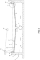
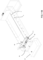
- Figure 1 schematically depicts a 3D view of part of a stable 1.
- part of a stable floor is depicted, where most part of a walk-on floor 2 is removed.
- Figure 1 shows the current ventilation system 7 and the current waste-removal system 6. These two systems each provide advantages, and when implemented together these two systems reduce emission and prevent pests in the stable 1.
- the depicted embodiment has collecting floor 3 below the walk-on floor 2. This collecting floor 3 is liquid closed. In an embodiment with the ventilation system, the collecting floor 3 is furthermore substantially air closed.
- the collecting floor 3 in the depicted embodiment furthermore comprise a discharge channel 4, in particular an open gutter.
- the collecting floor 3 is provided for receiving waste that falls through the walk-on floor 2.
- the walk-on floor 2 has openings for allowing waste to fall onto the collecting floor 3. In the depicted embodiment, it is a slatted floor, that is largely removed for showing the further construction.
- the depicted embodiment is further provided with a waste displacer for the solid waste fraction.
- that waste displacer comprises a waste scraper 5, also called a dung slider ® . Waste that drops onto the collecting floor 3 is removed quickly by the waste scraper 5 into a further closed system in order to prevent emission.
- the collecting floor 3 is at a slope, sloping towards a discharge channel 4.
- the waste scraper 5 in use moves back and forth over the collecting floor. In this way, the waste is displaced.
- the waste is displaced to and into the displacement channel 4.
- the displacement to the discharge channel is a first concentrating step.
- the upper surface of the collecting floor 3 is relatively smooth in order to facilitate displacement of the waste. Furthermore, the collecting floor 3 is liquid-closed. In an embodiment, coupling of the collecting floor 3 to the further stable construction is liquid-closed in order to prevent waste from polluting the stable.
- the waste scraper 5 has a lower edge contacting the collecting floor 3 in order to ensure, in operation, that the waste is properly displaced and removed from the collecting floor 3.
- the liquid fraction of the waste, mainly urine in the waste removal system 6 is introduced in a closed waste drainage conduit 11.
- the waste drainage conduit 11 is provided below the collecting floor 3.
- the waste drainage conduit 11 can also be provided below the walk-on floor and above the collecting floor.
- a waste drainage conduit 25 is positioned between the walk-on floor 2 and the collecting floor 3. That embodiment will be discussed further below.
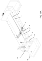
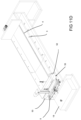
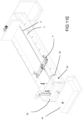
- the hood 28 is fluidly coupled to a flexible conduit 29, here a flexible hose 29.
- the flexible conduit 29 is here provided on an automatic line reel or winder or reeling drum 30.
- the waste scraper 5 with hood 28 in operation runs back and forth along a length of the collecting floor 3.
- the flexible conduit 29 is fluidly coupled with the waste suction device. In operation, air and waste are sucked from the collecting floor 3.
- the flexible conduit provides a waste drainage conduit between the walk-on floor 2 and the collecting floor 3.
- the flexible hose 29 can provide an alternative waste drainage conduit. It may extend in the discharge channel. In an alternative, it may provide a reduced pressure in the hood 28, for removing gasses or even waste from the collecting floor 3.
- the waste scraper 5 further comprises an actuator for displacing the waste scraper 5 back and forth along a length of the collecting floor 3.
- the waste scraper 5 can have one or two opposite waste displacement surfaces.
- the waste displacement surfaces depicted are planar.
- the waste displacement surface in order to displace waste effectively to the discharge channel 4, can be angled, having its center at the discharge channel.
- the displacement surface has two displacement surface parts angled towards the discharge channel 4.
Landscapes
- Life Sciences & Earth Sciences (AREA)
- Environmental Sciences (AREA)
- Zoology (AREA)
- Animal Husbandry (AREA)
- Biodiversity & Conservation Biology (AREA)
- Housing For Livestock And Birds (AREA)
- External Artificial Organs (AREA)
Applications Claiming Priority (3)
| Application Number | Priority Date | Filing Date | Title |
|---|---|---|---|
| NL2028707 | 2021-07-12 | ||
| NL2031024 | 2022-02-21 | ||
| EP22184560.5A EP4173478B1 (fr) | 2021-07-12 | 2022-07-12 | Étable comprenant un système d'élimination de déchets |
Related Parent Applications (2)
| Application Number | Title | Priority Date | Filing Date |
|---|---|---|---|
| EP22184560.5A Division EP4173478B1 (fr) | 2021-07-12 | 2022-07-12 | Étable comprenant un système d'élimination de déchets |
| EP22184560.5A Previously-Filed-Application EP4173478B1 (fr) | 2021-07-12 | 2022-07-12 | Étable comprenant un système d'élimination de déchets |
Publications (2)
| Publication Number | Publication Date |
|---|---|
| EP4581925A2 true EP4581925A2 (fr) | 2025-07-09 |
| EP4581925A3 EP4581925A3 (fr) | 2025-12-31 |
Family
ID=82557979
Family Applications (2)
| Application Number | Title | Priority Date | Filing Date |
|---|---|---|---|
| EP25159893.4A Pending EP4581925A3 (fr) | 2021-07-12 | 2022-07-12 | Étable comprenant un système d'élimination de déchets |
| EP22184560.5A Active EP4173478B1 (fr) | 2021-07-12 | 2022-07-12 | Étable comprenant un système d'élimination de déchets |
Family Applications After (1)
| Application Number | Title | Priority Date | Filing Date |
|---|---|---|---|
| EP22184560.5A Active EP4173478B1 (fr) | 2021-07-12 | 2022-07-12 | Étable comprenant un système d'élimination de déchets |
Country Status (1)
| Country | Link |
|---|---|
| EP (2) | EP4581925A3 (fr) |
Citations (9)
| Publication number | Priority date | Publication date | Assignee | Title |
|---|---|---|---|---|
| FR2848065A1 (fr) | 2002-12-10 | 2004-06-11 | Queguiner Ind | Fond de fosse pour installation d'evacuation du lisier d'un batiment d'elevage |
| WO2010058384A1 (fr) | 2008-11-24 | 2010-05-27 | MT Højgaard A/S | Système de conduits de ventilation et procédé pour réduire au minimum la pollution de l'air dans et/ou autour d'une structure d'habitat animal |
| NL2004491C2 (nl) | 2010-03-31 | 2011-10-04 | G Van Beek & Zn Betonindustrie B V | Vloerbalk voor een stalvloer en een stalvloer voorzien van een dergelijke vloerbalk. |
| NL2004490C2 (nl) | 2010-03-31 | 2011-10-04 | G Van Beek & Zn Kalverstalinrichting B V | Vloerbalk voor een stalvloer en een stalvloer voorzien van een dergelijke vloerbalk. |
| EP2494864A1 (fr) | 2011-03-04 | 2012-09-05 | G. van Beek & Zn. Kalverstalinrichting B.V. | Étable avec fosse à lisier |
| NL2014138A (nl) | 2015-01-14 | 2016-09-26 | Lauka Holding B V | Rundveestal voorzien van een ondergrondse mestkelder waarin onderdruk heerst |
| US20160316712A1 (en) | 2015-05-01 | 2016-11-03 | Kee3, Llc | Livestock production facility |
| EP3289859A1 (fr) | 2014-06-18 | 2018-03-07 | G. van Beek & Zn. Kalverstalinrichting B.V. | Racleur de fumier |
| WO2020187804A1 (fr) | 2019-03-15 | 2020-09-24 | G. Van Beek & Zn. Kalverstalinrichting B.V. | Étable comprenant un système de ventilation et un système d'élimination des déchets |
Family Cites Families (1)
| Publication number | Priority date | Publication date | Assignee | Title |
|---|---|---|---|---|
| DK200401851A (da) * | 2004-11-26 | 2006-05-27 | Scan Plast Ind As | Gylleanlæg til svinestald |
-
2022
- 2022-07-12 EP EP25159893.4A patent/EP4581925A3/fr active Pending
- 2022-07-12 EP EP22184560.5A patent/EP4173478B1/fr active Active
Patent Citations (9)
| Publication number | Priority date | Publication date | Assignee | Title |
|---|---|---|---|---|
| FR2848065A1 (fr) | 2002-12-10 | 2004-06-11 | Queguiner Ind | Fond de fosse pour installation d'evacuation du lisier d'un batiment d'elevage |
| WO2010058384A1 (fr) | 2008-11-24 | 2010-05-27 | MT Højgaard A/S | Système de conduits de ventilation et procédé pour réduire au minimum la pollution de l'air dans et/ou autour d'une structure d'habitat animal |
| NL2004491C2 (nl) | 2010-03-31 | 2011-10-04 | G Van Beek & Zn Betonindustrie B V | Vloerbalk voor een stalvloer en een stalvloer voorzien van een dergelijke vloerbalk. |
| NL2004490C2 (nl) | 2010-03-31 | 2011-10-04 | G Van Beek & Zn Kalverstalinrichting B V | Vloerbalk voor een stalvloer en een stalvloer voorzien van een dergelijke vloerbalk. |
| EP2494864A1 (fr) | 2011-03-04 | 2012-09-05 | G. van Beek & Zn. Kalverstalinrichting B.V. | Étable avec fosse à lisier |
| EP3289859A1 (fr) | 2014-06-18 | 2018-03-07 | G. van Beek & Zn. Kalverstalinrichting B.V. | Racleur de fumier |
| NL2014138A (nl) | 2015-01-14 | 2016-09-26 | Lauka Holding B V | Rundveestal voorzien van een ondergrondse mestkelder waarin onderdruk heerst |
| US20160316712A1 (en) | 2015-05-01 | 2016-11-03 | Kee3, Llc | Livestock production facility |
| WO2020187804A1 (fr) | 2019-03-15 | 2020-09-24 | G. Van Beek & Zn. Kalverstalinrichting B.V. | Étable comprenant un système de ventilation et un système d'élimination des déchets |
Also Published As
| Publication number | Publication date |
|---|---|
| EP4581925A3 (fr) | 2025-12-31 |
| EP4173478B1 (fr) | 2025-02-26 |
| EP4173478A1 (fr) | 2023-05-03 |
Similar Documents
| Publication | Publication Date | Title |
|---|---|---|
| EP3937619A1 (fr) | Étable comprenant un système de ventilation et un système d'élimination des déchets | |
| KR101894095B1 (ko) | 바이오커튼과 이온수를 이용하여 축사의 악취를 저감하는 방법 | |
| CN112470951B (zh) | 全自动宠物猫厕所 | |
| US20040040516A1 (en) | Method of reducing emission of ammonia from animal manure, a plant for performing the method and a use of such plant | |
| WO2020040244A1 (fr) | Enclos pour animal, système de réduction d'odeur pour enclos pour animal, dispositif de désodorisation, et système de ventilation pour enclos pour animal | |
| CN111685042A (zh) | 一种畜牧养殖用牛羊饲养房智能新风除臭装置 | |
| CN110036921A (zh) | 基于漏缝地板的养殖舍粪污实时分离收运系统 | |
| EP3707997A1 (fr) | Étable comprenant un système de ventilation et un système d'élimination de déchets | |
| KR101891697B1 (ko) | 동물 사육시설의 분뇨처리 시스템 | |
| EP4173478B1 (fr) | Étable comprenant un système d'élimination de déchets | |
| KR101008567B1 (ko) | 악취저감형 돈사 | |
| KR20110003155A (ko) | 분진 및 냄새 제거장치 | |
| JPH07256236A (ja) | 水に含まれる有機成分の除去装置 | |
| KR100889486B1 (ko) | 축분 악취 제거 시스템 | |
| NL2025127B1 (en) | Stable comprising a ventilation system and a waste removal system | |
| NL2025132B1 (en) | Stable comprising a ventilation system and a waste removal system | |
| EP3707996A1 (fr) | Étable comprenant un système de ventilation et un système d'élimination de déchets | |
| EP1618054A2 (fr) | Dispositif de collecte de dechets equipe d'un systeme de ventilation | |
| CN211064587U (zh) | 一种便于清理兔子排泄物的兔笼 | |
| US7810454B2 (en) | Animal breeding plant | |
| CN109704533B (zh) | 非液态粪污微氧式贮存系统及方法 | |
| WO2006058537A1 (fr) | Installation de purin pour porcherie | |
| JP2020174566A (ja) | 畜舎およびその換気システム | |
| JP2020032407A (ja) | 脱臭装置及び畜舎の臭気低減システム | |
| CN111066658A (zh) | 一种环保猪舍 |
Legal Events
| Date | Code | Title | Description |
|---|---|---|---|
| STAA | Information on the status of an ep patent application or granted ep patent |
Free format text: STATUS: UNKNOWN |
|
| PUAI | Public reference made under article 153(3) epc to a published international application that has entered the european phase |
Free format text: ORIGINAL CODE: 0009012 |
|
| STAA | Information on the status of an ep patent application or granted ep patent |
Free format text: STATUS: THE APPLICATION HAS BEEN PUBLISHED |
|
| AC | Divisional application: reference to earlier application |
Ref document number: 4173478 Country of ref document: EP Kind code of ref document: P |
|
| AK | Designated contracting states |
Kind code of ref document: A2 Designated state(s): AL AT BE BG CH CY CZ DE DK EE ES FI FR GB GR HR HU IE IS IT LI LT LU LV MC MK MT NL NO PL PT RO RS SE SI SK SM TR |
|
| REG | Reference to a national code |
Ref country code: DE Ref legal event code: R079 Free format text: PREVIOUS MAIN CLASS: A01K0001010000 Ipc: A01K0001000000 |
|
| RIC1 | Information provided on ipc code assigned before grant |
Ipc: A01K 1/00 20060101AFI20250903BHEP Ipc: A01K 1/01 20060101ALI20250903BHEP |
|
| PUAL | Search report despatched |
Free format text: ORIGINAL CODE: 0009013 |
|
| AK | Designated contracting states |
Kind code of ref document: A3 Designated state(s): AL AT BE BG CH CY CZ DE DK EE ES FI FR GB GR HR HU IE IS IT LI LT LU LV MC MK MT NL NO PL PT RO RS SE SI SK SM TR |
|
| RIC1 | Information provided on ipc code assigned before grant |
Ipc: A01K 1/00 20060101AFI20251125BHEP Ipc: A01K 1/01 20060101ALI20251125BHEP |