EP4580326A1 - Wärmeableitungsvorrichtung, leistungsmodul, stromversorgungssystem, fahrzeug und fotovoltaisches system - Google Patents
Wärmeableitungsvorrichtung, leistungsmodul, stromversorgungssystem, fahrzeug und fotovoltaisches system Download PDFInfo
- Publication number
- EP4580326A1 EP4580326A1 EP23905587.4A EP23905587A EP4580326A1 EP 4580326 A1 EP4580326 A1 EP 4580326A1 EP 23905587 A EP23905587 A EP 23905587A EP 4580326 A1 EP4580326 A1 EP 4580326A1
- Authority
- EP
- European Patent Office
- Prior art keywords
- heat dissipation
- pillars
- dissipation device
- pillar
- bottom plate
- Prior art date
- Legal status (The legal status is an assumption and is not a legal conclusion. Google has not performed a legal analysis and makes no representation as to the accuracy of the status listed.)
- Pending
Links
Images


Classifications
-
- H—ELECTRICITY
- H05—ELECTRIC TECHNIQUES NOT OTHERWISE PROVIDED FOR
- H05K—PRINTED CIRCUITS; CASINGS OR CONSTRUCTIONAL DETAILS OF ELECTRIC APPARATUS; MANUFACTURE OF ASSEMBLAGES OF ELECTRICAL COMPONENTS
- H05K7/00—Constructional details common to different types of electric apparatus
- H05K7/20—Modifications to facilitate cooling, ventilating, or heating
- H05K7/2089—Modifications to facilitate cooling, ventilating, or heating for power electronics, e.g. for inverters for controlling motor
- H05K7/20927—Liquid coolant without phase change
-
- H—ELECTRICITY
- H02—GENERATION; CONVERSION OR DISTRIBUTION OF ELECTRIC POWER
- H02M—APPARATUS FOR CONVERSION BETWEEN AC AND AC, BETWEEN AC AND DC, OR BETWEEN DC AND DC, AND FOR USE WITH MAINS OR SIMILAR POWER SUPPLY SYSTEMS; CONVERSION OF DC OR AC INPUT POWER INTO SURGE OUTPUT POWER; CONTROL OR REGULATION THEREOF
- H02M7/00—Conversion of AC power input into DC power output; Conversion of DC power input into AC power output
- H02M7/003—Constructional details, e.g. physical layout, assembly, wiring or busbar connections
-
- H—ELECTRICITY
- H02—GENERATION; CONVERSION OR DISTRIBUTION OF ELECTRIC POWER
- H02S—GENERATION OF ELECTRIC POWER BY CONVERSION OF INFRARED RADIATION, VISIBLE LIGHT OR ULTRAVIOLET LIGHT, e.g. USING PHOTOVOLTAIC [PV] MODULES
- H02S40/00—Components or accessories in combination with PV modules, not provided for in groups H02S10/00 - H02S30/00
- H02S40/30—Electrical components
- H02S40/32—Electrical components comprising DC/AC inverter means associated with the PV module itself, e.g. AC modules
-
- H—ELECTRICITY
- H05—ELECTRIC TECHNIQUES NOT OTHERWISE PROVIDED FOR
- H05K—PRINTED CIRCUITS; CASINGS OR CONSTRUCTIONAL DETAILS OF ELECTRIC APPARATUS; MANUFACTURE OF ASSEMBLAGES OF ELECTRICAL COMPONENTS
- H05K7/00—Constructional details common to different types of electric apparatus
- H05K7/20—Modifications to facilitate cooling, ventilating, or heating
- H05K7/2089—Modifications to facilitate cooling, ventilating, or heating for power electronics, e.g. for inverters for controlling motor
- H05K7/209—Heat transfer by conduction from internal heat source to heat radiating structure
-
- H—ELECTRICITY
- H05—ELECTRIC TECHNIQUES NOT OTHERWISE PROVIDED FOR
- H05K—PRINTED CIRCUITS; CASINGS OR CONSTRUCTIONAL DETAILS OF ELECTRIC APPARATUS; MANUFACTURE OF ASSEMBLAGES OF ELECTRICAL COMPONENTS
- H05K7/00—Constructional details common to different types of electric apparatus
- H05K7/20—Modifications to facilitate cooling, ventilating, or heating
- H05K7/2089—Modifications to facilitate cooling, ventilating, or heating for power electronics, e.g. for inverters for controlling motor
- H05K7/20909—Forced ventilation, e.g. on heat dissipaters coupled to components
-
- H—ELECTRICITY
- H10—SEMICONDUCTOR DEVICES; ELECTRIC SOLID-STATE DEVICES NOT OTHERWISE PROVIDED FOR
- H10W—GENERIC PACKAGES, INTERCONNECTIONS, CONNECTORS OR OTHER CONSTRUCTIONAL DETAILS OF DEVICES COVERED BY CLASS H10
- H10W40/00—Arrangements for thermal protection or thermal control
- H10W40/40—Arrangements for thermal protection or thermal control involving heat exchange by flowing fluids
- H10W40/47—Arrangements for thermal protection or thermal control involving heat exchange by flowing fluids by flowing liquids, e.g. forced water cooling
-
- H—ELECTRICITY
- H02—GENERATION; CONVERSION OR DISTRIBUTION OF ELECTRIC POWER
- H02M—APPARATUS FOR CONVERSION BETWEEN AC AND AC, BETWEEN AC AND DC, OR BETWEEN DC AND DC, AND FOR USE WITH MAINS OR SIMILAR POWER SUPPLY SYSTEMS; CONVERSION OF DC OR AC INPUT POWER INTO SURGE OUTPUT POWER; CONTROL OR REGULATION THEREOF
- H02M1/00—Details of apparatus for conversion
- H02M1/32—Means for protecting converters other than automatic disconnection
- H02M1/327—Means for protecting converters other than automatic disconnection against abnormal temperatures
-
- H—ELECTRICITY
- H02—GENERATION; CONVERSION OR DISTRIBUTION OF ELECTRIC POWER
- H02M—APPARATUS FOR CONVERSION BETWEEN AC AND AC, BETWEEN AC AND DC, OR BETWEEN DC AND DC, AND FOR USE WITH MAINS OR SIMILAR POWER SUPPLY SYSTEMS; CONVERSION OF DC OR AC INPUT POWER INTO SURGE OUTPUT POWER; CONTROL OR REGULATION THEREOF
- H02M3/00—Conversion of DC power input into DC power output
- H02M3/003—Constructional details, e.g. physical layout, assembly, wiring or busbar connections
Definitions
- This application relates to the field of semiconductor technologies, and in particular, to a heat dissipation apparatus, a power assembly, a power supply system, a vehicle, and a photovoltaic system.
- Power assemblies play an important role in the new energy industry, and are core components in the fields such as new energy vehicles and smart photovoltaics.
- An operating power device in a power assembly is frequently switched between a turn-on state and a turn-off state, and implements conversion between an alternating current voltage and a direct current voltage by switching between the two states, to provide a proper voltage for a load.
- frequent state switching causes a heat loss of the power assembly, including a turn-on loss and a turn-off loss. Both the turn-on loss and the turn-off loss bring a large amount of heat to the power assembly, and a high temperature causes a decrease in conversion efficiency of the power assembly or even causes damage to the power assembly.
- the power assembly serves as a core component of a power supply system, and the decrease in conversion efficiency of the power assembly and the damage to the power assembly greatly affect the entire power supply system.
- a heat dissipation apparatus is usually mounted in the power assembly, and a cooling medium flows into the heat dissipation apparatus to exchange heat with a power device that generates heat.
- a problem that different parts of a heat dissipation apparatus currently used in a power assembly generate different amounts of heat is not considered, resulting in poor cooling effect of the heat dissipation apparatus on the power assembly.
- This application provides a heat dissipation apparatus that can improve cooling effect on a power module, a power assembly, a power supply system, a vehicle, and a photovoltaic system.
- this application provides a heat dissipation apparatus.
- the heat dissipation apparatus includes a bottom plate, a first heat dissipation device, and a second heat dissipation device, the bottom plate includes a first surface and a second surface that are disposed opposite to each other, the first heat dissipation device and the second heat dissipation device are stacked on the first surface in a thickness direction of the bottom plate, the first heat dissipation device is located between the first surface and the second heat dissipation device, and the second surface is configured to fasten a power module, to dissipate heat for the power module.
- a plurality of first heat dissipation pillars spaced apart are disposed in the first heat dissipation device, a plurality of second heat dissipation pillars spaced apart are disposed in the second heat dissipation device, and after a cooling medium flows into the first heat dissipation device and the second heat dissipation device, a flow rate in first heat dissipation channels between all the first heat dissipation pillars in the first heat dissipation device is greater than a flow rate in second heat dissipation channels between all the second heat dissipation pillars in the second heat dissipation device.
- One of functions of the bottom plate is to fasten the first heat dissipation device and the second heat dissipation device.
- the first surface of the bottom plate is connected to the first heat dissipation device, the bottom plate, the first heat dissipation device, and the second heat dissipation device are stacked in the thickness direction of the bottom plate, and the thickness direction of the bottom plate is defined as a first direction.
- Another function of the bottom plate is to transfer heat from the power module to the heat dissipation apparatus.
- the second surface of the bottom plate is fastened to the power module, and heat generated by a power device in the power module is transferred to the second surface of the bottom plate through a metal layer-clad substrate, and then is in contact with the first heat dissipation device and the second heat dissipation device through the first surface of the bottom plate.
- the second surface of the bottom plate is welded to the power module through solder, and the bottom plate is made of a thermally conductive material. This helps reduce thermal resistance of the heat dissipation apparatus.
- the first heat dissipation device and the second heat dissipation device are configured to: connect to a cooling system, and transmit a cooling medium provided by the cooling system.
- the cooling medium in the first heat dissipation device and the second heat dissipation device exchanges heat with the power module, and the heat dissipation apparatus takes the heat away from the power module, to reduce a temperature of the power device in a steady working state, and control a temperature of the power module.
- the cooling medium is non-conductive pure water.
- the cooling medium may be any one of fluoride, methyl silicone oil, silicone oil, and mineral oil.
- the plurality of first heat dissipation pillars are spaced apart in the first heat dissipation device, and the plurality of second heat dissipation pillars are spaced apart in the second heat dissipation device.
- the first heat dissipation pillars and the second heat dissipation pillars can increase a contact area between the heat dissipation apparatus and the cooling medium, to enhance turbulence of the cooling medium, and improve a surface heat transfer coefficient.
- the first heat dissipation pillars divide the first heat dissipation device into the first heat dissipation channels that are connected to each other
- the second heat dissipation pillars divide the second heat dissipation device into the second heat dissipation channels that are connected to each other
- gaps between the first heat dissipation pillars and gaps between the second heat dissipation pillars form heat dissipation channels
- the cooling medium may flow into a gap between any two adjacent first heat dissipation pillars
- the cooling medium may flow into a gap between any two adjacent second heat dissipation pillars.
- flow channels of the cooling medium in the heat dissipation apparatus are connected to each other. This helps reduce flow resistance of the cooling medium, and improves heat dissipation
- the first heat dissipation device is connected to the first surface of the bottom plate, and the second surface of the bottom plate is connected to the power module, the first heat dissipation device is closer to the power module than the second heat dissipation device.
- the power module generates a large amount of heat when the power module is in a working state, a temperature of the first heat dissipation device closer to the power module is higher than a temperature of the second heat dissipation device.
- a side that is of the heat dissipation device and that is close to the power module has a high temperature and large thermal resistance.
- a heat dissipation condition of a heat dissipation device close to the power module is poor due to local overheating, and overall cooling efficiency of the heat dissipation apparatus is also affected.
- the flow rate in the first heat dissipation channels between all the first heat dissipation pillars in the first heat dissipation device is set to be greater than the flow rate in the second heat dissipation channels between all the second heat dissipation pillars in the second heat dissipation device, and flow resistance of the cooling medium is small, so that cooling effect of the first heat dissipation device is stronger, and the first heat dissipation device is cooperated with the second heat dissipation device. This helps the heat dissipation apparatus conduct heat, and improves overall heat dissipation effect of the heat dissipation apparatus.
- the first heat dissipation channels between all the first heat dissipation pillars are a sum of the gaps between all the first heat dissipation pillars
- the second heat dissipation channels between all the second heat dissipation pillars are a sum of the gaps between all the second heat dissipation pillars.
- the heat dissipation apparatus is disposed in a power assembly.
- the first heat dissipation pillars and the second heat dissipation pillars increase a contact area between the cooling medium and the first heat dissipation device and a contact area between the cooling medium and the second heat dissipation device, thereby helping improve heat exchange efficiency.
- the first heat dissipation pillars divide the first heat dissipation device into mutually connected flow channels
- the second heat dissipation pillars divide the second heat dissipation device into mutually connected flow channels, so that flow resistance of the cooling medium in the first heat dissipation device and the second heat dissipation device is small.
- fluid resistance of all the first heat dissipation pillars in the first heat dissipation device is less than fluid resistance of all the second heat dissipation pillars in the first heat dissipation device. Smaller fluid resistance may indicate smaller resistance endured by the cooling medium during flowing and a larger flow rate in the first heat dissipation device. This helps improve cooling effect of the first heat dissipation device.
- Fluid resistance is resistance endured by an object from a fluid when the object moves relative to the fluid in the fluid (a liquid or a gas).
- fluid resistance of the first heat dissipation pillar is resistance endured by the first heat dissipation pillar from the cooling medium when the first heat dissipation pillar moves relative to the cooling medium in the cooling medium; and fluid resistance of the second heat dissipation pillar is resistance endured by the second heat dissipation pillar from the cooling medium when the second heat dissipation pillar moves relative to the cooling medium in the cooling medium.
- shapes of the first heat dissipation pillar and the second heat dissipation pillar are set, so that the fluid resistance of the first heat dissipation pillar is less than the fluid resistance of the second heat dissipation pillar.
- the first heat dissipation channels and the second heat dissipation channels are configured to allow the cooling medium to circulate.
- the volumes of the first heat dissipation channels between all the first heat dissipation pillars in the first heat dissipation device are set to be greater than the volumes of the second heat dissipation channels between all the second heat dissipation pillars in the second heat dissipation device, so that after the cooling medium flows into the first heat dissipation device and the second heat dissipation device, the flow rate in the first heat dissipation device is greater than the flow rate in the second heat dissipation device.
- the volumes of the first heat dissipation channels between all the first heat dissipation pillars in the first heat dissipation device may alternatively be set to be less than or equal to the volumes of the second heat dissipation channels between all the second heat dissipation pillars in the second heat dissipation device.
- more complex structures and arrangement manners of the first heat dissipation pillars and the second heat dissipation pillars need to be designed, so that the flow rate in the first heat dissipation device is greater than the flow rate in the second heat dissipation device.
- the volumes of the first heat dissipation channels are set to be greater than the volumes of the second heat dissipation channels.
- the volumes of the first heat dissipation channels are set to be greater than the volumes of the second heat dissipation channels. Because the first heat dissipation channels are larger, the cooling medium has smaller flow resistance and a larger flow rate in the first heat dissipation channels, so that the first heat dissipation device has stronger cooling effect, and the first heat dissipation device is cooperated with the second heat dissipation device. This helps the heat dissipation apparatus conduct heat, and improves overall heat dissipation effect of the heat dissipation apparatus.
- an area enclosed by first heat dissipation pillars located at an outermost edge of the first heat dissipation device is equal to an area enclosed by second heat dissipation pillars located at an outermost edge of the second heat dissipation device, and the length of the first heat dissipation device in the first direction is set to be greater than the length of the second heat dissipation device in the first direction, so that the volumes of the first heat dissipation channels between all the first heat dissipation pillars in the first heat dissipation device are greater than the volumes of the second heat dissipation channels between all the second heat dissipation pillars in the second heat dissipation device.
- the flow rate and a flow velocity of the cooling medium in the first heat dissipation device are greater than the flow rate and a flow velocity of the cooling medium in the second heat dissipation device. This helps improve cooling effect of the first heat dissipation device, and improves a temperature distribution status of the heat dissipation apparatus.
- the first heat dissipation pillar and the second heat dissipation pillar have a same cross-sectional area, and a quantity of first heat dissipation pillars is the same as a quantity of second heat dissipation pillars.
- the volumes of the first heat dissipation channels between all the first heat dissipation pillars in the first heat dissipation device can be greater than the volumes of the second heat dissipation channels between all the second heat dissipation pillars in the second heat dissipation device only by setting the length of the first heat dissipation device in the first direction to be greater than the length of the second heat dissipation device in the first direction.
- a length of the first heat dissipation pillar in the thickness direction of the bottom plate is greater than a length of the second heat dissipation pillar in the thickness direction of the bottom plate.
- a larger length of the first heat dissipation pillar in the first direction indicates a larger contact area between the first heat dissipation pillar and the cooling medium and better flow disturbing effect of the first heat dissipation pillar on the cooling medium. This helps improve cooling effect of the first heat dissipation device.
- a spacing between every two first heat dissipation pillars in the first heat dissipation device is greater than a spacing between every two second heat dissipation pillars in the second heat dissipation device.
- a second direction is parallel to the first surface of the bottom plate, and perpendicularly intersects the first direction.
- the spacing between every two first heat dissipation pillars in the first heat dissipation device may be a spacing in the second direction, or may be a spacing in any direction parallel to the first surface.
- the spacing between every two first heat dissipation pillars is a spacing between the two first heat dissipation pillars in the second direction
- the spacing between every two second heat dissipation pillars is a spacing between the two second heat dissipation pillars in the second direction.
- the spacing between every two first heat dissipation pillars is set to be greater than the spacing between every two second heat dissipation pillars, so that the volumes of the first heat dissipation channels between all the first heat dissipation pillars in the first heat dissipation device are greater than the volumes of the second heat dissipation channels between all the second heat dissipation pillars in the second heat dissipation device.
- flow resistance of the cooling medium between every two first heat dissipation pillars is less than flow resistance of the cooling medium between every two second heat dissipation pillars. This helps increase a flow velocity of the cooling medium in the first heat dissipation device. In addition, a higher flow velocity of the cooling medium indicates better heat exchange effect, thereby properly distributing the cooling medium in the first heat dissipation device and the second heat dissipation device.
- a length of the first heat dissipation device in the second direction is the same as a length of the second heat dissipation device in the second direction.
- distribution density of the first heat dissipation pillars in the first heat dissipation device is less than distribution density of the second heat dissipation pillars in the second heat dissipation device, and a smaller space volume occupied by the first heat dissipation pillars in the first heat dissipation device indicates larger volumes of the first heat dissipation channels through which the cooling medium flows. Therefore, flow resistance of the first heat dissipation device is smaller, and cooling effect of the first heat dissipation device is improved.
- an area of a cross section of the first heat dissipation pillar is less than an area of a cross section of the second heat dissipation pillar, and both the cross section of the first heat dissipation pillar and the cross section of the second heat dissipation pillar are perpendicular to the thickness direction of the bottom plate.
- Both the cross section of the first heat dissipation pillar and the cross section of the second heat dissipation pillar are parallel to the second direction and the first surface of the bottom plate.
- Two end faces of the first heat dissipation pillar in the first direction have a same shape and a same area
- two end faces of the second heat dissipation pillar in the first direction have a same shape and a same area.
- the first heat dissipation pillar and the second heat dissipation pillar are square pillars and cylinders.
- a same shape and a same area herein are not limited to being absolutely the same, and may be understood as being basically the same, and a case in which shapes and areas are not absolutely the same due to factors such as an assembly tolerance, a design tolerance, and structural flatness is allowed.
- the area of the cross section of the first heat dissipation pillar is set to be less than the area of the cross section of the second heat dissipation pillar, so that a spacing between every two first heat dissipation pillars is larger, and the volumes of the first heat dissipation channels through which the cooling medium flows are larger. This helps reduce flow resistance of the cooling medium in the first heat dissipation device.
- the area of the cross section of the first heat dissipation device is not equal to the area of the cross section of the second heat dissipation device, the area of the cross section of the first heat dissipation pillar is set to be less than the area of the cross section of the second heat dissipation pillar, so that a flow volume of the cooling medium in the first heat dissipation device is larger.
- a volume of the first heat dissipation pillar is less than a volume of the second heat dissipation pillar.
- the volume of the first heat dissipation pillar is set to be less than the volume of the second heat dissipation pillar, so that the volumes of the first heat dissipation channels through which the cooling medium flows in the first heat dissipation device are greater than the volumes of the second heat dissipation channels through which the cooling medium flows in the second heat dissipation device, thereby effectively improving cooling efficiency of the cooling medium in the first heat dissipation device.
- two end faces of the first heat dissipation pillar in the first direction are different, and two end faces of the second heat dissipation pillar in the first direction are different.
- the first heat dissipation pillar is used as an example for description.
- the two end faces of the first heat dissipation pillar in the first direction have a same shape but different areas.
- the first heat dissipation pillar is a cylindrical table pillar.
- the two end faces of the first heat dissipation pillar in the first direction have different shapes but a same area.
- the first heat dissipation pillar is chopstick-shaped.
- the two end faces of the first heat dissipation pillar in the first direction have different shapes and different areas.
- the first heat dissipation pillar is a conical pillar, a triangular pillar, an olive shape, an ellipsoid shape, an hourglass shape, a dumbbell shape, a water droplet shape, or an irregular shape.
- the foregoing implementation may adapt to different application scenarios, so that the heat dissipation apparatus is more diversified.
- a quantity of first heat dissipation pillars is less than a quantity of second heat dissipation pillars.
- the quantity of first heat dissipation pillars is set to be less than the quantity of second heat dissipation pillars, so that distribution density of the first heat dissipation pillars in the first heat dissipation device can be less than distribution density of the second heat dissipation pillars in the second heat dissipation device.
- the cooling medium When the cooling medium separately flows into the first heat dissipation device and the second heat dissipation device, the cooling medium encounters less blockage from the first heat dissipation pillars and fewer collisions between the first heat dissipation pillars and the cooling medium, so that the cooling medium flows more smoothly in the first heat dissipation device. This helps the cooling medium fully utilize heat dissipation effect.
- the first heat dissipation pillar and the second heat dissipation pillar have a same shape, a total volume of internal space of the first heat dissipation device is equal to a total volume of internal space of the second heat dissipation device, and a quantity of first heat dissipation pillars is less than a quantity of second heat dissipation pillars. In this way, distribution density of the first heat dissipation pillars in the first heat dissipation device is less than distribution density of the second heat dissipation pillars in the second heat dissipation device.
- the cooling medium When the cooling medium separately flows into the first heat dissipation device and the second heat dissipation device, the cooling medium encounters less blockage from the first heat dissipation pillars and fewer collisions between the first heat dissipation pillars and the cooling medium, so that the cooling medium flows more smoothly in the first heat dissipation device. This helps the cooling medium fully utilize heat dissipation effect.
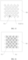
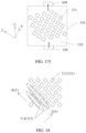
- an orthographic projection of at least one of the plurality of first heat dissipation pillars on the first surface and an orthographic projection of at least one of the plurality of second heat dissipation pillars on the first surface are staggered.
- space in which the cooling medium exchanges heat is the first heat dissipation channels between all the first heat dissipation pillars in the first heat dissipation device and the second heat dissipation channels between all the second heat dissipation pillars in the second heat dissipation device, and the first heat dissipation pillars and the second heat dissipation pillars have a higher heat conduction capability than the cooling medium.
- an orthographic projection of at least one first heat dissipation pillar on the first surface and an orthographic projection of at least one second heat dissipation pillar on the first surface are set to be staggered, and the gaps between the first heat dissipation pillars partially overlap the second heat dissipation pillars, so that heat of the cooling medium in the gaps between the first heat dissipation pillars (or the first heat dissipation channels) can be transmitted upward to the second heat dissipation pillars.
- the second heat dissipation device can assist the first heat dissipation device in cooling, thereby improving cooling efficiency of the first heat dissipation device.
- Staggering means non-overlapping or incomplete overlapping.
- an orthographic projection of each of the plurality of first heat dissipation pillars on the first surface and an orthographic projection of each of the plurality of second heat dissipation pillars on the first surface are staggered. This solution helps further improve heat conduction effect.
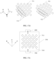
- the plurality of first heat dissipation pillars and the plurality of second heat dissipation pillars are all regularly arranged.
- the plurality of first heat dissipation pillars and the plurality of second heat dissipation pillars are regularly arranged, and at least one first heat dissipation pillar and one second heat dissipation pillar are staggered.
- the cooling medium in the first heat dissipation channels can transfer heat to the second heat dissipation pillars located above the first heat dissipation channels, and the second heat dissipation pillars directly absorb the heat in the first direction. This shortens a heat transfer path, and helps improve efficiency of heat exchange between the cooling medium in the first heat dissipation channels and the cooling medium in the second heat dissipation channels.
- the third direction intersects the fifth direction
- the fourth direction intersects the sixth direction.
- the third direction, the fourth direction, the fifth direction, and the sixth direction are all parallel to the first surface of the bottom plate.
- the third direction is set to intersect the fifth direction
- the fourth direction is set to intersect the sixth direction, so that the first heat dissipation pillars and the second heat dissipation pillars are arranged in different manners, and the orthographic projection of the first heat dissipation pillar on the first surface and the orthographic projection of the second heat dissipation pillar on the first surface are staggered, thereby improving cooling efficiency of the second heat dissipation device and the first heat dissipation device.
- the plurality of first heat dissipation pillars and the plurality of second heat dissipation pillars may alternatively be arranged according to another rule.
- the plurality of first heat dissipation pillars and the plurality of second heat dissipation pillars may be distributed in a radial shape or a concentric circle, provided that it is ensured that the orthographic projection of at least one of the first heat dissipation pillars on the first surface and the orthographic projection of at least one of the second heat dissipation pillars on the first surface are staggered.
- a quantity of first heat dissipation pillars in a group of first heat dissipation pillars first increases and then decreases in the third direction, so that all the first heat dissipation pillars form a square as a whole.
- a quantity of second heat dissipation pillars in a group of second heat dissipation pillars first increases and then decreases in the third direction, so that all the second heat dissipation pillars form a square as a whole.
- the heat dissipation apparatus further includes a liquid inlet and a liquid outlet, the liquid inlet and the liquid outlet are respectively located on two sides of the first heat dissipation device and the second heat dissipation device in a seventh direction, and the seventh direction intersects the third direction, the fourth direction, the fifth direction, and the sixth direction, so that after the cooling medium enters the first heat dissipation device and the second heat dissipation device, a degree of mixing of the cooling medium is higher, thereby improving heat dissipation effect.
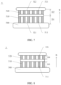
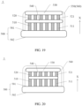
- the heat dissipation apparatus further includes a top plate, a partition plate, and a side frame that are located on one side of the first surface, the partition plate is disposed between the top plate and the first surface in the thickness direction of the bottom plate, the side frame surrounds a peripheral side of the partition plate, one end of the side frame in the thickness direction of the bottom plate is sealed with the first surface, and the other end of the side frame in the thickness direction of the bottom plate is sealed with the top plate; and the first heat dissipation device is located in space enclosed by the bottom plate, the partition plate, and a part that is of the side frame and that is between the bottom plate and the partition plate, and the second heat dissipation device is located in space enclosed by the partition plate, the top plate, and a part that is of the side frame and that is between the partition plate and the top plate.
- the first heat dissipation pillars are located between the first surface and the partition plate, and the second heat dissipation pillars are located between the partition plate and the top plate.
- the top plate forms a part of the second heat dissipation device, and the top plate is connected to the second heat dissipation pillars. This helps prevent the cooling medium from leaking from the top of fins of the second heat dissipation pillars, improves utilization of the cooling medium, and enhances heat dissipation effect.
- two ends of the side frame are respectively sealed with the top plate and the first surface in the first direction. This helps enhance stability of the heat dissipation apparatus, and ensures that the cooling medium is not affected by an external environment and stably functions in the heat dissipation apparatus.
- the side frame is sealed with the top plate and the first surface through welding.
- the heat dissipation apparatus includes a water channel bottom cover; the top plate, the second heat dissipation pillars, the partition plate, and the first heat dissipation pillars are all located in the water channel bottom cover; and the water channel bottom cover is in a groove shape, and an opening end of the water channel bottom cover is sealed with the first surface through welding.
- the side frame is a peripheral part of the water channel bottom cover.
- the water channel bottom cover is disposed in the heat dissipation apparatus, to help prevent the cooling medium from leaking from the top of fins of the second heat dissipation pillars.
- the side frame is the water channel bottom cover, and penetrates the water channel bottom cover in the first direction, and two ends of the water channel bottom cover are respectively sealed with the top plate and the first surface through welding.
- a material of the water channel bottom cover may be different from a material of the top plate and a material of the partition plate.
- the side frame is disposed as a part of the water channel bottom cover, so that the water channel bottom cover can cooperate with the top plate to jointly prevent the cooling medium from leaking from the heat dissipation apparatus, thereby improving utilization of the cooling medium by the heat dissipation apparatus, and improving cooling effect.
- the heat dissipation apparatus is not additionally provided with a water channel bottom cover, the side frame is welded to the top plate and the first surface, and a material of the side frame is the same as a material of the top plate and a material of the partition plate.
- manufacturing costs of the heat dissipation apparatus are reduced while ensuring that the cooling medium is not prone to leak.
- the first heat dissipation pillars and the bottom plate are of an integrally formed structure
- the second heat dissipation pillars and the partition plate are of an integrally formed structure
- the first heat dissipation pillars, the partition plate, and the second heat dissipation pillars are of an integrally formed structure.
- the integrally formed structure can effectively improve stability of the heat dissipation apparatus, so that the first heat dissipation pillars and the second heat dissipation pillars in the heat dissipation apparatus do not shake in a process of cooling the power module.
- the integrally formed structure helps reduce processing difficulty and manufacturing costs of the heat dissipation apparatus.
- the liquid inlet and the liquid outlet of the heat dissipation apparatus are located on two sides of the side frame in the seventh direction.
- the liquid inlet and the liquid outlet are connected to an external cooling system, and are configured to: input an external cooling medium into the heat dissipation apparatus through the liquid inlet, and output the external cooling medium through the liquid outlet.
- a high-temperature cooling medium flowing out of the liquid outlet is cooled by the external cooling system and then flows into the heat dissipation apparatus again through the liquid inlet.
- the heat dissipation apparatus further includes a third heat dissipation device, a plurality of third heat dissipation pillars spaced apart are disposed in the third heat dissipation device, the third heat dissipation device is located on a side that is of the second heat dissipation device and that is away from the bottom plate, and after the cooling medium flows into the second heat dissipation device and the third heat dissipation device, the flow rate in the second heat dissipation channels between all the second heat dissipation pillars in the second heat dissipation device is greater than a flow rate in third heat dissipation channels between all the third heat dissipation pillars in the third heat dissipation device.
- the third heat dissipation channels are configured to allow the cooling medium to circulate, and volumes of the third heat dissipation channels are less than the volumes of the second heat dissipation channels.
- the volumes of the third heat dissipation channels are set to be less than the volumes of the second heat dissipation channels, so that after the cooling medium flows into the second heat dissipation device and the third heat dissipation device, a flow rate in the third heat dissipation device is less than the flow rate in the second heat dissipation device.
- the fluid resistance of the second heat dissipation pillar is less than fluid resistance of the third heat dissipation pillar.
- the fluid resistance of the third heat dissipation pillar is resistance endured by the third heat dissipation pillar from the cooling medium when the third heat dissipation pillar moves relative to the cooling medium in the cooling medium.
- Shapes of the second heat dissipation pillar and the third heat dissipation pillar are set, so that the fluid resistance of the second heat dissipation pillar is less than the fluid resistance of the third heat dissipation pillar.
- the third heat dissipation channels may alternatively be set to be greater than or equal to the second heat dissipation channels, but more complex structures and arrangement manners of the third heat dissipation pillars and the second heat dissipation pillars need to be designed, so that the flow rate in the third heat dissipation device is less than the flow rate in the second heat dissipation device.
- the volumes of the third heat dissipation channels are set to be less than the volumes of the second heat dissipation channels.
- this application provides a power assembly, including a power module and the heat dissipation apparatus according to any implementation of the first aspect.
- the power module is fastened to a second surface.
- orientation terms such as “up” and “down” are defined relative to orientations of schematically placed structures in the accompanying drawings. It should be understood that these directional terms are relative concepts and are used for relative description and clarification, and may vary accordingly with changes of the orientations of the structures.
- MOSFET Metal-Oxide-Semiconductor Field-Effect Transistor, metal-oxide-semiconductor field-effect transistor.
- the heat dissipation apparatus provided in this application may be used in the power assembly, and the power assembly including the heat dissipation apparatus in this application may be used in a photovoltaic system and a power supply system of a vehicle.
- the vehicle 2 includes an electric vehicle/electric vehicle (Electric Vehicle, EV for short), a pure electric vehicle (Pure Electric Vehicle/Battery Electric Vehicle, PEV/BEV for short), a hybrid electric vehicle (Hybrid Electric Vehicle, HEV for short), a range extended electric vehicle (Range Extended Electric Vehicle, REEV for short), a plug-in hybrid vehicle (Plug-in Hybrid Electric Vehicle, PHEV for short), a new energy vehicle (New Energy Vehicle), or the like.
- the vehicle 2 includes a passenger vehicle and various special operation vehicles with specific functions, for example, an engineering rescue vehicle, a sprinkler, a sewage sucker, a cement mixer, a crane, and a medical vehicle.
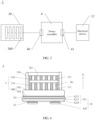
- the power supply system 1 includes an inverter (not shown in the figure), the power assembly 4 and a control circuit (not shown in the figure) are disposed in the inverter, the control circuit is electrically connected to the power assembly 4, and the control circuit may control, based on a requirement of the vehicle 2, a performance parameter of an alternating current output by the power assembly 4 to the motor, for example, a voltage, a current, a quantity of cycles, or a frequency.
- FIG. 3 is a diagram of a structure of the photovoltaic system 3 according to an embodiment of this application.
- the photovoltaic system 3 includes a photovoltaic module 30 and the power assembly 4, the photovoltaic module 30 is electrically connected to the power assembly 4, and a direct current generated by the photovoltaic module 30 is converted into an alternating current through the power assembly 4.
- the alternating current output by the power assembly 4 is transmitted to the electrical device 12, for example, a base station or a data center.
- the photovoltaic module 30 includes at least one photovoltaic panel 300, and the photovoltaic panel 300 is connected to the power assembly 4.
- the photovoltaic module 30 includes a plurality of photovoltaic panels 300 connected in series, and direct currents of the plurality of photovoltaic panels 300 are converged in a series connection manner, and then are connected to the power assembly 4 through a connector.
- the photovoltaic system 3 includes an inverter (not shown in the figure), the power assembly 4 and a control circuit (not shown in the figure) are disposed in the inverter, the control circuit is electrically connected to the power assembly 4, and the control circuit may control, based on a requirement of the electrical device 12, a performance parameter of the alternating current output by the power assembly 4, for example, a voltage, a current, a quantity of cycles, or a frequency.
- FIG. 4 is a diagram of a structure of the power assembly 4 according to an embodiment of this application.
- the power assembly 4 includes a power module 42 and a heat dissipation apparatus 5, and the power module 42 includes power devices 420 and a metal layer-clad substrate 421 that are stacked in a first direction X.
- the power device 420 is a power electronic device that can implement a power conversion function, and includes but is not limited to a MOSFET, an IGBT, a gate resistor, or a temperature sensor.
- the first metal layer 4210 is welded to the power devices 420 through first solder S1
- the second metal layer 4212 is welded to the heat dissipation apparatus 5 through second solder S2.
- the first solder S1 and the second solder S2 may be selected from at least one of tin solder and lead solder
- the tin solder is selected from at least one of SnSb5, SnSb8, SnSbAg, SAC305, SAC multi-component reinforcement, and SnSb10
- materials of the first solder S1 and the second solder S2 may be selected based on a requirement
- the first solder S1 and the second solder S2 may be the same or different.
- the metal layer-clad substrate 421 may be a direct bond copper (Direct Bond Copper, DBC) ceramic substrate, an active metal brazed copper (Active metal brazed copper, AMB, for example, Al 2 O 3 -AMB, Si 3 N 4 -AMB, or AlN-AMB) substrate, an insulated metal substrate (Insulated metal substrate, IMS), or the like.
- DBC Direct Bond Copper
- AMB active metal brazed copper
- IMS Insulated metal substrate
- the heat dissipation apparatus 5 is improved, so that flow resistance of the cooling medium on a side that is of the heat dissipation apparatus 5 and that is close to the power module 42 is smaller, thereby helping improve the cooling effect of the heat dissipation apparatus 5.
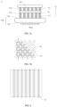
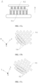
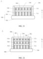
- FIG. 5a is a diagram of a structure of the heat dissipation apparatus 5 according to an embodiment of this application
- FIG. 5b is a top view of first heat dissipation pillars 511 in the heat dissipation apparatus 5 according to an embodiment of this application.
- This application provides the heat dissipation apparatus 5.
- the heat dissipation apparatus 5 includes a bottom plate 500, a first heat dissipation device 510, and a second heat dissipation device 520 (as shown in FIG. 5a ).
- the bottom plate 500 includes a first surface 501 and a second surface 502 that are disposed opposite to each other (as shown in FIG. 5a ).
- the first heat dissipation device 510 and the second heat dissipation device 520 are stacked on the first surface 501 in a thickness direction X of the bottom plate 500 (as shown in FIG. 5a ), and the first heat dissipation device 510 is located between the first surface 501 and the second heat dissipation device 520 (as shown in FIG. 5a ).
- the second surface 502 is used to fasten the power module 42 (as shown in FIG. 4 ), to dissipate heat for the power module 42.
- a plurality of first heat dissipation pillars 511 spaced apart are disposed in the first heat dissipation device 510 (as shown in FIG. 5a and FIG. 5b ), and a plurality of second heat dissipation pillars 521 spaced apart are disposed in the second heat dissipation device 520 (as shown in FIG. 5a ).
- a flow rate in first heat dissipation channels K1 between all the first heat dissipation pillars 511 in the first heat dissipation device 510 is greater than a flow rate in second heat dissipation channels K2 between all the second heat dissipation pillars 521 in the second heat dissipation device 520.
- One of functions of the bottom plate 500 is to fasten the first heat dissipation device 510 and the second heat dissipation device 520.
- the first surface 501 of the bottom plate 500 is connected to the first heat dissipation device 510 (as shown in FIG. 4 ), the bottom plate 500, the first heat dissipation device 510, and the second heat dissipation device 520 are stacked in the thickness direction X of the bottom plate 500, and the thickness direction X of the bottom plate 500 is defined as a first direction X.
- Another function of the bottom plate 500 is to transfer heat from the power module 42 to the heat dissipation apparatus 5.
- the second surface 502 of the bottom plate 500 is fastened to the power module 42 (as shown in FIG. 4 ), and heat generated by the power device 420 in the power module 42 is transferred to the second surface 502 of the bottom plate 500 through the metal layer-clad substrate 421, and then is in contact with the first heat dissipation device 510 and the second heat dissipation device 520 through the first surface 501 of the bottom plate 500.
- the second surface 502 of the bottom plate 500 is welded to the power module 42 through solder, and the bottom plate 500 is made of a thermally conductive material. This helps reduce thermal resistance of the heat dissipation apparatus 5.
- the first heat dissipation device 510 and the second heat dissipation device 520 are configured to: connect to a cooling system (not shown in the figure), and transmit a cooling medium provided by the cooling system.
- a cooling system not shown in the figure
- the cooling medium in the first heat dissipation device 510 and the second heat dissipation device 520 exchanges heat with the power module 42, and the heat dissipation apparatus 5 takes the heat away from the power module 42, to reduce a temperature of the power device 420 in a steady working state, and control a temperature of the power module 42.
- the cooling medium is non-conductive pure water.
- the cooling medium may be any one of fluoride, methyl silicone oil, silicone oil, and mineral oil. A person skilled in the art may select a type of the cooling medium based on an actual requirement. This is not limited in this application.
- the plurality of first heat dissipation pillars 511 are spaced apart in the first heat dissipation device 510, and the plurality of second heat dissipation pillars 521 are spaced apart in the second heat dissipation device 520.
- the first heat dissipation pillars 511 and the second heat dissipation pillars 521 can increase a contact area between the heat dissipation apparatus 5 and the cooling medium, to enhance turbulence of the cooling medium, and improve a surface heat transfer coefficient.
- the first heat dissipation pillars 511 divide the first heat dissipation device 510 into the first heat dissipation channels K1 that are connected to each other (as shown in FIG. 5b ), the second heat dissipation pillars 521 divide the second heat dissipation device 520 into the second heat dissipation channels K2 that are connected to each other, and gaps between the first heat dissipation pillars 511 and gaps between the second heat dissipation pillars 521 form heat dissipation channels.
- the first heat dissipation device 510 is connected to the first surface 501 of the bottom plate 500, and the second surface 502 of the bottom plate 500 is connected to the power module 42, the first heat dissipation device 510 is closer to the power module 42 than the second heat dissipation device 520.
- a temperature of the first heat dissipation device 510 closer to the power module 42 is higher than a temperature of the second heat dissipation device 520.
Landscapes
- Engineering & Computer Science (AREA)
- Microelectronics & Electronic Packaging (AREA)
- Physics & Mathematics (AREA)
- Thermal Sciences (AREA)
- Power Engineering (AREA)
- Cooling Or The Like Of Electrical Apparatus (AREA)
Applications Claiming Priority (2)
| Application Number | Priority Date | Filing Date | Title |
|---|---|---|---|
| CN202223453727.4U CN220274101U (zh) | 2022-12-22 | 2022-12-22 | 散热装置、功率模组、电源系统、车辆及光伏系统 |
| PCT/CN2023/132920 WO2024131418A1 (zh) | 2022-12-22 | 2023-11-21 | 散热装置、功率模组、电源系统、车辆及光伏系统 |
Publications (2)
| Publication Number | Publication Date |
|---|---|
| EP4580326A1 true EP4580326A1 (de) | 2025-07-02 |
| EP4580326A4 EP4580326A4 (de) | 2026-01-21 |
Family
ID=89310869
Family Applications (1)
| Application Number | Title | Priority Date | Filing Date |
|---|---|---|---|
| EP23905587.4A Pending EP4580326A4 (de) | 2022-12-22 | 2023-11-21 | Wärmeableitungsvorrichtung, leistungsmodul, stromversorgungssystem, fahrzeug und fotovoltaisches system |
Country Status (3)
| Country | Link |
|---|---|
| EP (1) | EP4580326A4 (de) |
| CN (1) | CN220274101U (de) |
| WO (1) | WO2024131418A1 (de) |
Family Cites Families (11)
| Publication number | Priority date | Publication date | Assignee | Title |
|---|---|---|---|---|
| DE102011089886A1 (de) * | 2011-12-23 | 2013-02-07 | Continental Automotive Gmbh | Schaltungsträger und Verfahren zur Herstellung von einem Schaltungsträger |
| WO2013157467A1 (ja) * | 2012-04-16 | 2013-10-24 | 富士電機株式会社 | 半導体装置および半導体装置用冷却器 |
| CN206136542U (zh) * | 2016-09-05 | 2017-04-26 | 北京能高自动化技术股份有限公司 | 一种均温式水冷散热器 |
| CN110543069A (zh) * | 2018-05-28 | 2019-12-06 | 中强光电股份有限公司 | 液冷式散热器 |
| KR20210088329A (ko) * | 2020-01-06 | 2021-07-14 | 엘지전자 주식회사 | 전력 모듈 |
| CN113316370B (zh) * | 2021-06-03 | 2026-01-02 | 苏州汇川联合动力系统股份有限公司 | 换热组件、散热结构及电机控制器 |
| CN215008207U (zh) * | 2021-06-24 | 2021-12-03 | 比亚迪半导体股份有限公司 | 一种散热板、半导体功率模块及车辆 |
| CN217606806U (zh) * | 2021-12-23 | 2022-10-18 | 比亚迪股份有限公司 | 功率模块及车辆 |
| CN114093832A (zh) * | 2021-12-27 | 2022-02-25 | 广东芯聚能半导体有限公司 | 散热底板及功率模块 |
| CN217444376U (zh) * | 2022-03-18 | 2022-09-16 | 比亚迪半导体股份有限公司 | 一种散热底板、功率模块、电子设备以及车辆 |
| CN115101498B (zh) * | 2022-05-18 | 2025-03-14 | 华为数字能源技术有限公司 | 功率模块、电源系统、车辆及光伏系统 |
-
2022
- 2022-12-22 CN CN202223453727.4U patent/CN220274101U/zh active Active
-
2023
- 2023-11-21 WO PCT/CN2023/132920 patent/WO2024131418A1/zh not_active Ceased
- 2023-11-21 EP EP23905587.4A patent/EP4580326A4/de active Pending
Also Published As
| Publication number | Publication date |
|---|---|
| EP4580326A4 (de) | 2026-01-21 |
| WO2024131418A1 (zh) | 2024-06-27 |
| CN220274101U (zh) | 2023-12-29 |
Similar Documents
| Publication | Publication Date | Title |
|---|---|---|
| EP3076428B1 (de) | Kühler und kühlerbefestigungsverfahren | |
| EP4642176A1 (de) | Wärmeableitungsvorrichtung zur flüssigkeitskühlung, elektromotorsteuereinheit, leistungsanordnung und elektrofahrzeug | |
| JP5506749B2 (ja) | 電力変換装置 | |
| US9419535B2 (en) | Electric power converter | |
| EP4415496B1 (de) | Wechselrichtervorrichtung zur verwendung in einer motorsteuerung, motorsteuerung und fahrzeug | |
| US9306020B2 (en) | Power module and method of manufacturing the power module | |
| US9437797B2 (en) | Cooling structure of heating element and power conversion device | |
| KR20140005813A (ko) | 반도체 장치 | |
| EP4254485A1 (de) | Leistungsmodul | |
| EP4654768A1 (de) | Leistungsmodul mit flüssigkeitskühlungskühler, motorsteuerung, antriebsstrang und fahrzeug | |
| US10178813B2 (en) | Stacked power module with integrated thermal management | |
| JP2016100442A (ja) | 半導体モジュール及び半導体装置 | |
| EP4580326A1 (de) | Wärmeableitungsvorrichtung, leistungsmodul, stromversorgungssystem, fahrzeug und fotovoltaisches system | |
| CN115911665A (zh) | 一种动力电池的汇流排冷却装置及电动车辆 | |
| JP5687786B2 (ja) | 電力変換装置 | |
| JP2017112279A (ja) | 半導体装置 | |
| JP7640332B2 (ja) | 回路基板内に電気部品を内蔵する半導体装置 | |
| CN113488445A (zh) | 一种igbt封装散热结构及其应用的电机控制器 | |
| US20230005812A1 (en) | Igbt package heating dissipation structure and motor controller applying the same | |
| JP7233510B1 (ja) | 電力変換装置 | |
| CN222515454U (zh) | 充电模块和充电设备 | |
| US20250266526A1 (en) | Housing element of a battery and battery comprising such a housing element | |
| WO2025195298A1 (zh) | 一种液冷散热器和功率模组 | |
| JP2025156822A (ja) | 電力変換装置 | |
| JP2025145247A (ja) | 半導体装置 |
Legal Events
| Date | Code | Title | Description |
|---|---|---|---|
| STAA | Information on the status of an ep patent application or granted ep patent |
Free format text: STATUS: THE INTERNATIONAL PUBLICATION HAS BEEN MADE |
|
| PUAI | Public reference made under article 153(3) epc to a published international application that has entered the european phase |
Free format text: ORIGINAL CODE: 0009012 |
|
| STAA | Information on the status of an ep patent application or granted ep patent |
Free format text: STATUS: REQUEST FOR EXAMINATION WAS MADE |
|
| 17P | Request for examination filed |
Effective date: 20250327 |
|
| AK | Designated contracting states |
Kind code of ref document: A1 Designated state(s): AL AT BE BG CH CY CZ DE DK EE ES FI FR GB GR HR HU IE IS IT LI LT LU LV MC ME MK MT NL NO PL PT RO RS SE SI SK SM TR |
|
| A4 | Supplementary search report drawn up and despatched |
Effective date: 20251218 |
|
| RIC1 | Information provided on ipc code assigned before grant |
Ipc: H05K 7/20 20060101AFI20251212BHEP Ipc: H01L 23/473 20060101ALI20251212BHEP Ipc: H02S 40/32 20140101ALI20251212BHEP Ipc: H02M 7/00 20060101ALI20251212BHEP Ipc: H02M 1/32 20070101ALI20251212BHEP Ipc: H02M 3/00 20060101ALI20251212BHEP |