EP4580306A2 - Doppelaktiver protokollstapelbetrieb für handover und pscell-wechsel - Google Patents
Doppelaktiver protokollstapelbetrieb für handover und pscell-wechsel Download PDFInfo
- Publication number
- EP4580306A2 EP4580306A2 EP25177134.1A EP25177134A EP4580306A2 EP 4580306 A2 EP4580306 A2 EP 4580306A2 EP 25177134 A EP25177134 A EP 25177134A EP 4580306 A2 EP4580306 A2 EP 4580306A2
- Authority
- EP
- European Patent Office
- Prior art keywords
- daps
- message
- handover
- base station
- procedure
- Prior art date
- Legal status (The legal status is an assumption and is not a legal conclusion. Google has not performed a legal analysis and makes no representation as to the accuracy of the status listed.)
- Pending
Links
Images


Classifications
-
- H—ELECTRICITY
- H04—ELECTRIC COMMUNICATION TECHNIQUE
- H04W—WIRELESS COMMUNICATION NETWORKS
- H04W36/00—Hand-off or reselection arrangements
- H04W36/0005—Control or signalling for completing the hand-off
- H04W36/0055—Transmission or use of information for re-establishing the radio link
- H04W36/0069—Transmission or use of information for re-establishing the radio link in case of dual connectivity, e.g. decoupled uplink/downlink
-
- H—ELECTRICITY
- H04—ELECTRIC COMMUNICATION TECHNIQUE
- H04W—WIRELESS COMMUNICATION NETWORKS
- H04W36/00—Hand-off or reselection arrangements
- H04W36/0005—Control or signalling for completing the hand-off
- H04W36/0011—Control or signalling for completing the hand-off for data sessions of end-to-end connection
- H04W36/0033—Control or signalling for completing the hand-off for data sessions of end-to-end connection with transfer of context information
-
- H—ELECTRICITY
- H04—ELECTRIC COMMUNICATION TECHNIQUE
- H04W—WIRELESS COMMUNICATION NETWORKS
- H04W36/00—Hand-off or reselection arrangements
- H04W36/16—Performing reselection for specific purposes
- H04W36/18—Performing reselection for specific purposes for allowing seamless reselection, e.g. soft reselection
- H04W36/185—Performing reselection for specific purposes for allowing seamless reselection, e.g. soft reselection using make before break
-
- H—ELECTRICITY
- H04—ELECTRIC COMMUNICATION TECHNIQUE
- H04W—WIRELESS COMMUNICATION NETWORKS
- H04W36/00—Hand-off or reselection arrangements
- H04W36/34—Reselection control
-
- H—ELECTRICITY
- H04—ELECTRIC COMMUNICATION TECHNIQUE
- H04W—WIRELESS COMMUNICATION NETWORKS
- H04W76/00—Connection management
- H04W76/30—Connection release
-
- H—ELECTRICITY
- H04—ELECTRIC COMMUNICATION TECHNIQUE
- H04W—WIRELESS COMMUNICATION NETWORKS
- H04W76/00—Connection management
- H04W76/30—Connection release
- H04W76/34—Selective release of ongoing connections
Definitions
- This disclosure relates generally to wireless communications and, more particularly, to dual active protocol stack (DAPS) operations related to handover and primary secondary cell (PSCell) change procedures.
- DAPS dual active protocol stack
- PSCell primary secondary cell
- the Packet Data Convergence Protocol (PDCP) sublayer of the radio protocol stack provides services such as transfer of user-plane data, ciphering, integrity protection, etc.
- the PDCP layer defined for the Evolved Universal Terrestrial Radio Access (EUTRA) radio interface (see 3GPP specification TS 36.323) and New Radio (NR) (see 3GPP specification TS 38.323) provides sequencing of protocol data units (PDUs) in the uplink direction (from a user device, also known as a user equipment (UE), to a base station) as well as in the downlink direction (from the base station to the UE).
- EUTRA Evolved Universal Terrestrial Radio Access
- NR New Radio
- the PDCP sublayer provides services for signaling radio bearers (SRBs) to the Radio Resource Control (RRC) sublayer.
- the PDCP sublayer also provides services for data radio bearers (DRBs) to a Service Data Adaptation Protocol (SDAP) sublayer or a protocol layer such as an Internet Protocol (IP) layer, an Ethernet protocol layer, and an Internet Control Message Protocol (ICMP) layer.
- SDAP Service Data Adaptation Protocol
- IP Internet Protocol
- ICMP Internet Control Message Protocol
- the UE and a base station can use SRBs to exchange RRC messages as well as non-access stratum (NAS) messages, and can use DRBs to transport data on a user plane.
- NAS non-access stratum
- SRB 1 resources carry RRC messages, which in some cases include NAS messages over the dedicated control channel (DCCH), and SRB2 resources support RRC messages that include logged measurement information or NAS messages, also over the DCCH but with lower priority than SRB 1 resources.
- DCCH dedicated control channel
- SRB2 resources support RRC messages that include logged measurement information or NAS messages, also over the DCCH but with lower priority than SRB 1 resources.
- SRB 1 and SRB2 resources allow the UE and the MN to exchange RRC messages related to the MN and embed RRC messages related to the SN, and also can be referred to as MCG SRBs.
- SRB3 resources allow the UE and the SN to exchange RRC messages related to the SN, and can be referred to as SCG SRBs.
- Split SRBs allow the UE to exchange RRC messages directly with the MN via lower layer resources of the MN and the SN.
- DRBs terminated at the MN and using the lower-layer resources of only the MN can be referred as MCG DRBs
- DRBs terminated at the SN and using the lower-layer resources of only the SN can be referred as SCG DRBs
- DRBs terminated at the MCG but using the lower-layer resources of the MN, the SN, or both the MN and the SN can be referred to as split DRBs.
- the UE in some scenarios can concurrently utilize resources of multiple nodes (e.g., base stations or components of a distributed base station) of a radio access network (RAN), interconnected by a backhaul.
- a radio access network RAN
- this type of connectivity is referred to as Multi-Radio Dual Connectivity (MR-DC).
- MR-DC Multi-Radio Dual Connectivity
- a UE When a UE operates in MR-DC, one base station operates as the MN that covers a primary cell (PCell), and the other base station operates as the SN that covers a primary secondary cell (PSCell). The UE communicates with the MN (via the PCell) and the SN (via the PSCell).
- the UE utilizes resources of one base station at a time.
- One base station and/or the UE determines that the UE should establish a radio connection with another base station. For example, one base station can determine to hand the UE over to the second base station, and initiate a handover procedure.
- the UE in other scenarios can concurrently utilize resources of a RAN node (e.g., a single base station or a component of a distributed base station), interconnected by a backhaul.
- a RAN node e.g., a single base station or a component of a distributed base station
- 3GPP TS 36.300 v15.6.0 and 38.300 v15.6.0 describe legacy procedures for handover (or called reconfiguration with sync) scenarios. These procedures involve messaging (e.g., RRC signaling and preparation) among RAN nodes and the UE.
- UEs can perform handover procedures to switch from one cell to another, whether in single connectivity (SC) or DC operation.
- SC single connectivity
- the UE may handover from a cell of a serving base station to a target cell of a target base station, or from a cell of a first distributed unit (DU) of a serving base station to a target cell of a second DU of the same base station, depending on the scenario.
- DU distributed unit
- 3GPP TS 37.340 v15.7.0 describes legacy procedures for a UE to change PSCells in DC scenarios. These procedures involve messaging (e.g., RRC signaling and preparation) among RAN nodes and the UE.
- the UE may perform PSCell change from a PSCell of a serving SN to a target PSCell of a target SN, or from a PSCell of a source distributed unit (DU) of a base station to a PSCell of a target DU of the same base station, depending on the scenario.
- DU distributed unit
- DAPS dual active protocol stack
- DAPS PSCell change procedures for achieving 0ms user data interruption during handover and PSCell change.
- the length of interruption experienced at the UE depends on a time difference between the time when a radio link connection at a source cell is released and the time when a radio link connection at a target cell is established. If the release time is no earlier than the established time, achieving 0ms user data interruption is possible.
- the UE can simultaneously communicate with the source cell while establishing a radio link connection at the target cell, and subsequently stop communicating with the source cell after establishing a radio link connection at the target cell, when performing DAPS handover and PSCell change.
- the RAN can provide a DAPS configuration (e.g., a DAPS handover configuration, a DAPS PSCell change configuration) to the UE for the UE to perform a DAPS handover or DAPS PSCell change, respectively.
- a DAPS configuration e.g., a DAPS handover configuration, a DAPS PSCell change configuration
- the UE and/or RAN do not properly handle the DAPS configuration.
- the UE may fail to perform DAPS handover or DAPS PSCell change upon receiving the DAPS configuration from a source RAN node, and as a consequence, the UE performs an RRC connection reestablishment procedure with the source RAN node to recover the reconfiguration failure, thereby causing data interruption.
- the source RAN node may be unaware that the UE is capable of DAPS handover or DAPS PSCell change, and as a consequence, fail to instruct the UE 102 to perform DAPS handover or DAPS PSCell change.
- a UE and one or more base stations operating in a RAN implement the techniques of this disclosure to prepare the UE to perform DAPS handover or DAPS PSCell change upon receiving a corresponding DAPS configuration (or an indication of the corresponding DAPS configuration).
- the RAN can configure a UE communicating with a base station via a plurality of cells to release some of the cells, so that radio frequency (RF) chain(s) or transceiver(s) of the UE that were previously operating when communicating with the released cells become available for use to perform DAPS handover or DAPS PSCell change.
- RF radio frequency
- the RAN can configure a UE communicating in dual connectivity (DC) with a master node (MN) and a secondary node (SN) to release the SN, so that RF chain(s) or transceiver(s) of the UE that were previously operating when communicating with the released SN become available for use to perform DAPS handover or DAPS PSCell change.
- DC dual connectivity
- MN master node
- SN secondary node
- One example implementation of these techniques is a method, in a RAN, for enabling execution of a DAPS procedure at a UE.
- the method includes determining, by processing hardware, that the UE is to release at least one cell via which the UE communicates with the RAN, prior to executing the DAPS procedure.
- the method also includes causing, by the processing hardware, the UE to release the at least one cell.
- the method also includes transmitting, by the processing hardware, a command to the UE to execute the DAPS procedure.
- Another example implementation of these techniques is a method, in a central unit (CU) of a distributed base station, for configuring a dual active protocol stack (DAPS) procedure at a UE communicating with the distributed base station via a source distributed unit (DU).
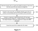
- the method includes determining, by the processing hardware and to the UE, that the UE is to perform the DAPS procedure to disconnect from the source DU and connect to a target DU.
- the method also includes transmitting, by the processing hardware and to the source DU, an indication that the source DU is to continue communicating with the UE during the DAPS procedure.
- the method also includes transmitting, in response to determining that the UE has begun communicating with the target DU, a release indication to the target DU, the release indication causing the target DU to release the DAPS procedure.
- the method also includes subsequently to transmitting the release indication, causing the source DU to release the UE context.
- Fig. 1A depicts an example wireless communication system 100 that can implement DAPS operation techniques of this disclosure.
- the wireless communication system 100 includes a UE 102, as well as base stations 104, 106A, 106B that are connected to a core network (CN) 110.
- the base stations 104, 106A, 106B can be any suitable type, or types, of base stations, such as an evolved node B (eNB), a next-generation eNB (ng-eNB), or a 5G Node B (gNB), for example.
- eNB evolved node B
- ng-eNB next-generation eNB
- gNB 5G Node B
- the base station 104 can be an eNB or a gNB
- the base stations 106A and 106B can be gNBs.
- the base station 104 supports a cell 124, the base station 106A supports a cell 126A, and the base station 106B supports a cell 126B.
- the cell 124 partially overlaps with both of cells 126A and 126B, such that the UE 102 can be in range to communicate with base station 104 while simultaneously being in range to communicate with base station 106A or 106B (or in range to detect or measure the signal from both base stations 106A or 106B, etc.).
- the overlap can make it possible for the UE 102 to hand over between cells (e.g., from cell 124 to cell 126A or 126B) or base stations ( e.g., from base station 104 to base station 106A or base station 106B) before the UE 102 experiences radio link failure, for example.
- the overlap allows the various dual connectivity (DC) scenarios discussed below.
- the UE 102 can communicate in DC with the base station 104 (operating as an MN) and the base station 106A (operating as an SN) and, upon completing a handover, can communicate with the base station 106B (operating as an MN).
- the UE 102 can communicate in DC with the base station 104 (operating as an MN) and the base station 106A (operating as an SN) and, upon completing an SN change, can communicate with the base station 104 (operating as an MN) and the base station 106B (operating as an SN).
- the base station 104 when the UE 102 is in DC with the base station 104 and the base station 106A, the base station 104 operates as a master eNB (MeNB), a master ng-eNB (Mng-eNB), or a master gNB (MgNB), and the base station 106A operates as a secondary gNB (SgNB) or a secondary ng-eNB (Sng-eNB).
- MeNB master eNB
- Mng-eNB master ng-eNB
- MgNB master gNB
- SgNB secondary gNB
- Sng-eNB secondary ng-eNB
- the base station 104 includes processing hardware 130, which can include one or more general-purpose processors (e.g., central processing units (CPUs) and a computer-readable memory storing machine-readable instructions executable on the one or more general-purpose processor(s), and/or special-purpose processing units.
- the processing hardware 130 in the example implementation in Fig. 1A includes a base station RRC controller 132 that is configured to manage or control RRC configurations and RRC procedures.
- the base station RRC controller 132 can be configured to support RRC messaging associated with DAPS handover and DAPS PSCell change procedures, and/or to support the necessary operations when the base station 104 operates as an MN, as discussed below.
- the base station 106A can be an EN-DC gNB (en-gNB) with an S1 interface to the EPC 111, an en-gNB that does not connect to the EPC 111, a gNB that supports the NR radio interface and an NG interface to the 5GC 160, or a ng-eNB that supports an EUTRA radio interface and an NG interface to the 5GC 160.
- en-gNB EN-DC gNB
- a gNB that supports the NR radio interface and an NG interface to the 5GC 160
- a ng-eNB that supports an EUTRA radio interface and an NG interface to the 5GC 160.
- the base stations 104, 106A, and 106B can support an X2 or Xn interface.
- the EPC 111 can include a Serving Gateway (S-GW) 112 and a Mobility Management Entity (MME) 114.
- S-GW 112 is generally configured to transfer user-plane packets related to audio calls, video calls, Internet traffic, etc.
- MME 114 is configured to manage authentication, registration, paging, and other related functions.
- the 5GC 160 includes a User Plane Function (UPF) 162 and an Access and Mobility Management (AMF) 164, and/or Session Management Function (SMF) 166.
- UPF User Plane Function
- AMF Access and Mobility Management
- SMF Session Management Function
- the UPF 162 is generally configured to transfer user-plane packets related to audio calls, video calls, Internet traffic, etc.
- the AMF 164 is configured to manage authentication, registration, paging, and other related functions
- the SMF 166 is configured to manage PDU sessions.
- the wireless communication network 100 can include any suitable number of base stations supporting NR cells and/or EUTRA cells.
- base station 104 and base station 106A can also support cells 122 and 123, respectively.
- the EPC 111 or the 5GC 160 can be connected to any suitable number of base stations supporting NR cells and/or EUTRA cells.
- EPC, 5GC and RAT types
- 5G NR and EUTRA the techniques of this disclosure can also apply to other suitable radio access and/or core network technologies such as sixth generation (6G) radio access and/or 6G core network or 5G NR-6G DC, for example.
- the wireless communication system 100 can support various procedures (e.g., DAPS handover, DAPS PSCell change, etc.) and modes of operation (e.g., SC or DC). Example operation of various procedures that can be implemented in the wireless communication system 100 will now be described.
- the wireless communication system 100 supports a legacy handover preparation procedure (i.e., a non-DAPS handover preparation procedure).
- the base station 104 can perform a non-DAPS handover preparation procedure to configure the UE 102 to handover from a cell 124 of the base station 104 to a cell 126A of the base station 106A.
- the base station 104 and the base station 106A operate as a source base station (S-BS) or a source MN (S-MN), and a target base station (T-BS) or a target MN (T-MN), respectively.
- S-BS source base station
- S-MN source MN
- T-BS target base station
- T-MN target MN
- the base station 104 sends a Handover Request message to the base station 106A.
- the base station 106A includes configuration parameters configuring radio resources for the UE 102 in a handover command message, includes the handover command message in a Handover Request Acknowledge message, and sends the Handover Request Acknowledge message to the base station 104.
- the base station 104 transmits the handover command message to the UE 102 and subsequently discontinues (or stops) transmitting data to or receiving data from the UE 102.
- the UE 102 Upon receiving the handover command message, the UE 102 hands over to the base station 106A via cell 126A and communicates with the base station 106A by using the configuration parameters in the handover command message. Particularly, in response to the handover command message, the UE 102 disconnects from the cell 124 (or the base station 104), performs a random access procedure with the base station 106A via the cell 126A, and transmits a handover complete message to the base station 106A via the cell 126A.
- the wireless communication system 100 supports a DAPS handover preparation procedure.
- the base station 104 can perform a DAPS handover preparation procedure to configure the UE 102 to hand over from a cell 124 of the base station 104 to a cell 126B of the base station 106B.
- the base station 104 and the base station 106B operate as an S-BS or an S-MN, and a T-BS or a T-MN, respectively.
- the base station 104 sends a Handover Request message to the base station 106B.
- the base station 104 can explicitly request DAPS handover in the Handover Request message, e.g., by including a DAPS indicator in the Handover Request message.
- the base station 106B includes configuration parameters configuring radio resources for the UE 102 in a handover command, includes the handover command message in a Handover Request Acknowledge message, and sends the Handover Request Acknowledge message to the base station 104.
- the base station 106B can indicate DAPS handover in the handover command message, e.g., by including a DAPS handover configuration or a DAPS handover indicator in the handover command message, or can include an indicator in the Handover Request Acknowledge message.
- the base station 104 transmits the handover command message to the UE 102.
- the UE 102 Upon receiving the handover command message, the UE 102 hands over to the base station 106B via cell 126B and communicates with the base station 106B by using the configuration parameters in the handover command message. Particularly, in response to the handover command message, whereas in the non-DAPS handover preparation procedure the UE 102 disconnects from the cell 124 (or the base station 104), the UE 102 in the DAPS handover preparation procedure maintains the connection to the base station 104 via cell 124, performs a random access procedure with the base station 106B via cell 126B, and transmits a handover complete message to the base station 106B via cell 126B.
- the UE 102 In maintaining the connection to the base station 104 via cell 124 in the DAPS handover preparation procedure, the UE 102 effectively has two links, i.e., a source MCG link with the base station 104 and a target MCG link with the base station 106B.
- the UE 102 can continue receiving data (i.e., downlink data) from the base station 104 until the UE 102 receives an indication from the base station 106B to release the source MCG link with the base station 104.
- the UE 102 can continue transmitting data (e.g ., new uplink data transmission or retransmission of PDCP SDUs) to the base station 104 until the UE 102 either successfully completes the random access procedure with the base station 106B or receives the indication from the base station 106B to release the MCG link with the base station 104.
- data e.g ., new uplink data transmission or retransmission of PDCP SDUs
- the wireless communication system 100 supports DC operation.
- the base station 104 can perform an SN addition procedure to add the base station 106A as an SN, thereby configuring the UE 102 to operate in DC with the base stations 104 and 106A.
- the base stations 104 and 106A operate as an MN and an SN, respectively.
- the MN 104 can initiate the non-DAPS or DAPS handover preparation procedures to handover the UE 102 to the T-MN 106B.
- the wireless communication system 100 supports a legacy PSCell change preparation procedure (i.e., a non-DAPS PSCell change preparation procedure).
- the UE 102 is initially in DC with the MN 104 ( e.g., via PCell 124) and the SN 106A (via a PSCell 123).
- the SN 106A can provide a configuration for the T-PSCell 126A, for the UE 102.
- the UE 102 stops communicating with the SN 106A via PSCell 123 and attempts to connect to the T-PSCell 126A after receiving the configuration for the T-PSCell 126A.
- the MN 104 determines to change the SN of the UE 102 from the base station 106A (which may be referred to as the source SN or S-SN) to the base station 106B (which may be referred to as the target SN or T-SN) as part of the non-DAPS PSCell change procedure.
- the UE 102 stops communicating with the S-SN 106A via PSCell 123 and attempts to connect to the T-SN 106B via T-PSCell 126B after receiving the configuration for the T-PSCell 126B.
- the base station 104 can operate as an MeNB, an Mng-eNB, or an MgNB
- the base station 106B can operate as an MeNB, an Mng-eNB, an MgNB, an SgNB, or an Sng-eNB
- the base station 106A can operate as an SgNB or an Sng-eNB.
- the UE 102 can communicate with the base station 104 and the base station 106A or 106B via the same radio access technology (RAT), such as EUTRA or NR, or via different RATs.
- RAT radio access technology
- the UE 102 can be in EUTRA-NR DC (EN-DC) with the MeNB 104 and the SgNB 106A.
- the UE 102 can be in next generation (NG) EUTRA-NR DC (NGEN-DC) with the Mng-eNB 104 and the SgNB 106A.
- the base station 104 is an MgNB and the base station 106A is an SgNB
- the UE 102 can be in NR-NR DC (NR-DC) with the MgNB 104 and the SgNB 106A.
- NR-DC NR-NR DC
- the base station 104 is an MgNB and the base station 106A is an Sng-eNB
- the UE 102 can be in NR-EUTRA DC (NE-DC) with the MgNB 104 and the Sng-eNB 106A.
- Fig. 1B depicts an example, distributed implementation of any one or more of the base stations 104, 106A, 106B.
- the base station 104, 106A, or 106B includes a centralized unit (CU) 172 and one or more distributed units (DUs) 174.
- the CU 172 includes processing hardware, such as one or more general-purpose processors (e.g ., CPUs) and a computer-readable memory storing machine-readable instructions executable on the general-purpose processor(s), and/or special-purpose processing units.
- the CU 172 can include the processing hardware 130 or 140 of Fig. 1A .
- the processing hardware can include a base station RRC controller (e.g., RRC controller 142) configured to manage or control one or more RRC configurations and/or RRC procedures when the base station (e.g ., base station 106A) operates as an SN.
- a base station RRC controller e.g., RRC controller 142 configured to manage or control one or more RRC configurations and/or RRC procedures when the base station (e.g ., base station 106A) operates as an SN.
- Each of the DUs 174 also includes processing hardware that can include one or more general-purpose processors (e.g ., CPUs) and computer-readable memory storing machine-readable instructions executable on the one or more general-purpose processors, and/or special-purpose processing units.
- the processing hardware can include a medium access control (MAC) controller configured to manage or control one or more MAC operations or procedures (e.g., a random access procedure), and a radio link control (RLC) controller configured to manage or control one or more RLC operations or procedures when the base station (e.g ., base station 106A) operates as a MN or an SN.
- the process hardware can also include a physical layer controller configured to manage or control one or more physical layer operations or procedures.
- Fig. 2 illustrates, in a simplified manner, an example dual active protocol stack (DAPS) 200 according to which the UE 102 can communicate with an eNB/ng-eNB or a gNB (e.g., one or more of the base stations 104, 106A, 106B).
- DAPS dual active protocol stack
- Fig. 3 through Fig. 5 correspond to DAPS handover scenarios in which a base station initiates a DAPS handover procedure for a UE.
- Fig. 6 through Fig. 8 correspond to DAPS PSCell change scenarios in which a base station initiates a DAPS PSCell change procedure for a UE.
- the S-BS 104 transmits 306 an RRC reconfiguration message to the UE 102 to configure the UE 102 to release M cells, where M is a whole number less than N ( i.e., 0 ⁇ M ⁇ N).
- the M cells can be one, some, or all of the SCells covered by the S-BS 104.
- the UE 102 releases 308 the M cells (i.e., the UE 102 disconnects from the M cells).
- the T-BS 106B In response to identifying the UE 102 during the random access procedure or receiving 324 the handover complete message, the T-BS 106B sends 328 a Handover Success message to the S-BS 104. After receiving the Handover Success message, the S-BS 104 stops 330 communicating with the UE 102. In some implementations, the S-BS 104 can transmit a sequence number (SN) Status Transfer message to the T-BS 106B in response to the Handover Success message. In some implementations, before or after transmitting the Handover Success message, the T-BS 106B can send an explicit stop indication message to the S-BS 104, which in turn can stop 330 communicating with the UE 102 in response to the explicit stop indication.
- SN sequence number
- the S-BS 104 determines to configure the UE 102 to release M cells according to a DAPS handover capability in a UE Capability information element (IE) of a message (e.g., in a UECapabilityInformation message) received from the UE 102, the CN 110 ( e.g., via a S1 or NG interface message), or another base station (e.g., the base station 106A, the base station 106B, or other base station not shown in Fig. 1A ) via an X2 or Xn interface.
- IE UE Capability information element
- the S-BS 104 can include the UE Capability IE in the Handover Request message in event 312 so that the T-BS 106B is aware of the DAPS handover capability of the UE 102.
- the UE Capability IE can be a UE-NR-Capability IE as defined in 3GPP TS 38.331 or a UE-EUTRA-Capability IE as defined in 3GPP TS 36.331.
- the S-BS 104 can perform a non-DAPS handover preparation procedure with the T-BS 106B.
- the T-BS 106B instead of generating the handover command message that includes the DAPS handover configuration (or an indication for the DAPS handover configuration) at event 314, the T-BS 106B generates a handover command message that excludes the DAPS handover configuration (or the indication for the DAPS handover configuration).
- the S-BS 104 determines to configure the UE 102 to release N-1 cells if the S-BS 104 is unaware whether the UE 102 is capable of DAPS handover with CA. The S-BS 104 can ensure that the UE 102 can perform DAPS handover by releasing the N-1 cells.
- cell 124 operates on a first DL carrier frequency and a first UL carrier frequency
- cell 126B operates on a second DL carrier frequency and a second UL carrier frequency.
- Cells 124 and 126B can be either FDD cells or TDD cells.
- the first DL carrier frequency and the first UL carrier frequency belong to a TDD band (i.e., the cell 124 is a TDD cell)
- the first DL carrier frequency and the first UL carrier frequency are the same or overlapped carrier frequencies.
- the first DL carrier frequency and the first UL carrier frequency belong to an FDD band (i.e., the cell 124 is an FDD cell)
- the DL carrier frequency and the UL carrier frequency are different carrier frequencies.
- cells 124 and 126B are either TDD cells or FDD cells and operate on the same or overlapped carrier frequencies. If the UE 102 is capable of the intra-frequency DAPS handover, the S-BS 104 can request the T-BS 106B to configure the cell 126B in the Handover Request message for the intra-frequency DAPS handover, and the T-BS 106B configures the cell 126B in the handover command message.
- the S-BS 104 requests the T-BS 106B to configure cell 126B in the Handover Request message for the intra-frequency non-DAPS handover, and the T-BS 106B configures the cell 126B in the handover command message.
- the DAPS handover capability indicates that the UE 102 is capable of inter-RAT DAPS handover using one or more indicators.
- the DAPS handover capability can include a single indicator indicating that the UE 102 is capable of inter-RAT DAPS handover from a cell of a first RAT (or a cell in a specific band in the first RAT) to a cell of a second RAT (or a cell in a specific band in the second RAT).
- the UE Capability IE can specify that the UE 102 is capable of inter-RAT DAPS handover, using an inter-RAT handover capability field/IE included in the UE Capability IE that indicates that the UE 102 is capable of inter-RAT DAPS handover from a first RAT to a second RAT. Therefore, the S-BS 104 or T-BS 106 can determine whether the UE 102 is capable of inter-RAT DAPS handover according to the DAPS handover capability and/or the UE Capability IE.
- the S-BS 104 or T-BS 106 determines that the UE 102 is capable of the inter-RAT non-DAPS handover.
- cell 124 operates in the first RAT (e.g ., EUTRA) and cell 126B operates in the second RAT (e.g., NR).
- the S-BS 104 can request the T-BS 106B to configure the cell 126B in the Handover Request message for the inter-RAT DAPS handover, and the T-BS 106B configures the cell 126B in the handover command message.
- the S-BS 104 requests the T-BS 106B to configure cell 126B in the Handover Request message for the inter-RAT non-DAPS handover, and the T-BS 106B configures the cell 126B in the handover command message.
- the "synchronous" and/or “asynchronous” indicators can be generic for or associated to all types of DAPS handover discussed above (e.g ., intra-frequency DAPS handover, inter-frequency DAPS handover, FDD-TDD DAPS handover, and/or inter-RAT DAPS handover) that the UE 102 supports.
- the S-BS 104 can send a Handover Request message to the T-BS 106B to request the T-BS 106B to prepare non-DAPS handover for the UE 102, and the T-BS 106B can configure the non-DAPS handover in the handover command message, in one implementation.
- the S-BS 104 can send a Handover Request message to the T-BS 106B to request the T-BS 106B to prepare DAPS handover for the UE 102, but the T-BS 106B can still configure the non-DAPS handover in the handover command message, and optionally notify the S-BS 104 of the non-DAPS handover for the UE 102. Otherwise, if the UE 102 supports asynchronous DAPS handover, the S-BS 104 can send a Handover Request message to the T-BS 106B to request the T-BS 106B to prepare DAPS handover for the UE 102.
- the S-BS 104 can send a Handover Request message to the T-BS 106B to request the T-BS 106B to prepare non-DAPS handover for the UE 102, in one implementation.
- the RRC reconfiguration procedure i.e., events 306, 308, 309, 310) and the DAPS handover preparation procedure (e.g ., events 312, 314, 316) can be performed in parallel, or in sequence.
- the S-BS 104 sends 312 the Handover Request message before or after transmitting 306 the RRC reconfiguration message or receiving 310 the RRC reconfiguration complete message, in one implementation.
- the S-BS 104 sends 312 the Handover Request message and sends 306 the RRC reconfiguration message at the same time.
- the UE 102 can continue DL communication (i.e., receiving control signals, reference signals, DL PDUs, etc.) with the S-BS 104 and/or transmit control signals (e.g ., HARQ acknowledgement, HARQ negative acknowledgement and/or channel state information) on PUCCH(s) to the S-BS 104 until event 332 occurs or a DAPS release timer at the UE 102 expires.
- control signals e.g ., HARQ acknowledgement, HARQ negative acknowledgement and/or channel state information
- the T-BS 106B configures a time value for the DAPS release timer in the handover command message or the RRC reconfiguration message in event 332.
- the UE 102 Upon receiving 318 the handover command message or receiving 332 the RRC reconfiguration message, the UE 102 starts the DAPS release timer.
- the UE 102 stops 336 communicating with the S-BS 104.
- the UE 102 uses a predetermined timer value if the T-BS 106B does not include the timer value in the handover command message or the RRC reconfiguration message.
- the T-BS 106B can include a timer value in the Handover Success message, which can be the same timer value in the RRC reconfiguration message in event 332 or larger than the timer value in the handover command message in event 318.
- the UE 102 exchanges RRC message with the S-BS 104 via SRB(s) (e.g., SRB1, SRB2 and/or SRB4) using the updated S-BS configuration before receiving the handover command message.
- the S-BS 104 can also include a DRB configuration in the updated S-BS configuration.
- the T-BS 106B includes multiple configuration parameters in the handover command message to configure radio resources for the UE 102 to communicate with the T-BS 106B via target PCell 126B.
- the multiple configuration parameters can configure zero, one, or more radio bearers, including SRB(s) (e.g., SRB1, SRB2 and/or SRB4) and/or DRB(s).
- the UE 102 can exchange RRC messages with the T-BS 106B via the SRB(s) ( i.e., SRB(s) for the target).
- the T-BS 106B can associate or otherwise specify the DAPS handover configuration to a radio bearer (e.g., DRB), such as by including the DAPS handover configuration in a DRB configuration ( e.g ., DRB-ToAddMod IE) in the handover command message.
- DRB radio bearer
- the UE 102 suspends the SRB(s) with the S-BS 104 (i.e., SRB(s) for the source).
- the DU(s) 174 can include one or more configuration parameters to update the S-BS configuration in the RRC reconfiguration message, so that the DU(s) 174 and the UE 102 can continue communicating with each other by using the updated S-BS configuration ( e.g ., at event 309).
- the DU(s) 174 can send the one or more configuration parameters to the CU 172.
- the UE 102 then transmits 410 an RRC reconfiguration complete message to the MN 104, and releases the SN configuration, in some implementations.
- the S-BS 104 may combine the RRC reconfiguration message (at event 406) and the handover command message (at event 410) into an RRC message.
- the S-BS 104 can generate an RRC message (e.g ., an RRC reconfiguration message) for releasing the SN that includes the handover command message, and transmit the RRC message to the UE 102 at event 418.
- the S-BS 104 can include the handover command message in a DAPS handover related field/IE.
- the handover command message may or may not include a DAPS handover related field/IE to indicate the DAPS handover.
- Figs. 6 through Figs. 8 correspond to DAPS PSCell change scenarios in which a base station initiates a DAPS PSCell change procedure for a UE in SC or in DC.
- Fig. 6 corresponds to DAPS PSCell change scenarios involving an SN change
- Figs. 7 and 8 correspond to DAPS PSCell change scenarios maintaining the same SN.
- the base station 104 operates as an MN for the UE 102
- the base station 106A operates as an S-SN for the UE 102
- the base station 106B operates as a T-SN for the UE 102.
- the UE 102 in DC communicates 602 data with the MN 104 via PCell 124 by using an MN configuration, and with the S-SN 106A via PSCell 126A by using an SN configuration.
- the MN 104 sends 612 an SN Addition Request message to the T-SN 106B.
- the T-SN 106B generates 614 an RRC reconfiguration message and a DAPS PSCell change configuration (or a DAPS SN change indicator), and sends 613 the RRC reconfiguration message and the DAPS PSCell change configuration in an SN Addition Request Acknowledge message to the MN 104.
- the MN 104 sends 615 an SN Release Request message (or alternatively, an SN Modification Request message) to the S-SN 106A to request the S-SN 106A to perform DAPS PSCell change or to continue communicating with the UE 102.
- the MN 104 may not send an SN Release Request message (or alternatively, an SN Modification Request message) to the S-SN 106A, causing the S-SN 106A to continue communicating with the UE 102 as the S-SN 106A is unaware of the DAPS SN change and therefore behaves as usual.
- the S-SN 106A In response to receiving 615 the SN Release Request message or the SN Modification Request message, the S-SN 106A continues communicating with the UE 102, and subsequently sends 616 an SN Release Request Acknowledge message or an SN Modification Request Acknowledge message to the MN 104, respectively.
- the MN 104 In response to receiving 613 the RRC reconfiguration message and the DAPS PSCell change configuration from the T-SN 106B, the MN 104 includes the RRC reconfiguration message and the DAPS PSCell change configuration in an RRC container message, and transmits 617 the RRC container message to the UE 102. In response, the UE 102 transmits 618 an RRC container response message including an RRC reconfiguration complete message to the MN 104. In some implementations, the MN 104 can send 619 an SN Reconfiguration Complete message to the T-SN 106B in response to the RRC container response message.
- the events 604, 612, 614, 613, 615, 616, 617, 618, 619 are collectively referred to in Fig. 6 as the DAPS PSCell change preparation procedure 660.
- the T-SN 106B can transmit 632 an RRC reconfiguration message that includes a DAPS release indicator to the UE 102, e.g., via an SRB ( e.g., SRB3) between the UE 102 and the T-SN 106B or via the MN 104.
- the UE 102 can transmit 634 an RRC reconfiguration complete message to the T-SN 106B via the SRB ( e.g., SRB3) between the UE 102 and the T-SN 106B or via the MN 104, and stop 636 communicating with the S-SN 106A.
- SRB e.g., SRB3
- the DAPS PSCell change capability can indicate that the UE 102 is capable of inter-frequency DAPS PSCell change for one or more frequency bands, or for FDD or TDD modes.
- the MN 104, S-SN 106A, or T-SN 106B determines that the UE 102 is capable of the inter-frequency DAPS PSCell change for one or more frequency bands by referring to the DAPS PSCell change capability.
- the DAPS PSCell change capability can generally indicate that the UE 102 is capable of DAPS PSCell change which may or may not exclude the intra-frequency DAPS PSCell change. Similar to the manner in which the UE Capability IE discussed above in Fig.
- the MN 104, S-SN 106A, T-SN 106B can determine that the UE 102 is capable of the inter-frequency DAPS PSCell change by referring to the DAPS PSCell change capability and the DC/CA band combination field/IE in a similar manner described above in Fig. 3 .
- the cells 126A and 126B are similar to cells 124 and 126B discussed above in Fig. 3 . Similar to the manner in which the S-BS 104 requests the T-BS 106B to configure DAPS handover or non-DAPS inter-frequency handover in the Handover Request message discussed above in Fig. 3 , the MN 104 can request the DAPS PSCell change or non-DAPS PSCell change in the SN Addition Request message. Similar to the manner in which the T-BS 106B configures cell 126B in the handover command message discussed above in Fig. 3 , the T-BS 106B configures the cell 126B in the RRC reconfiguration message.
- the DAPS PSCell change capability can indicate that the UE 102 is capable of intra-frequency DAPS PSCell change for one or more frequency bands, or for FDD and/or TDD modes.
- the MN 104, S-SN 106A, T-SN 106B can determine that the UE 102 is capable of the intra-frequency DAPS PSCell change by referring to the DAPS PSCell change capability and the DC/CA band combination field/IE in a similar manner described above in Fig. 3 .
- the cells 126A and 126B are similar to cells 124 and 126B discussed above in Fig. 3 . Similar to the manner in which the S-BS 104 requests the T-BS 106B to configure DAPS handover or non-DAPS intra-frequency handover in the Handover Request message discussed above in Fig. 3 , the MN 104 can request the DAPS PSCell change or non-DAPS PSCell change in the SN Addition Request message. Similar to the manner in which the T-BS 106B configures cell 126B in the handover command message discussed above in Fig. 3 , the T-SN 106B configures the cell 126B in the PSCell change command message.
- the DAPS PSCell change capability indicates that the UE 102 is capable of synchronous DAPS PSCell change and/or asynchronous DAPS PSCell change.
- the MN 104 can send an SN Addition Request message to request the T-SN 106B to prepare the DAPS PSCell change or non-DAPS PSCell change in an RRC reconfiguration message.
- the DAPS PSCell change scenario 700 does not involve an SN change.
- the UE 102 in DC communicates 702 data with the MN 104 via PCell 124 by using an MN configuration, and with the SN 106A via PSCell 123 by using an SN configuration.
- the SN 106A determines 704 to initiate DAPS PSCell change without involving an SN change (i.e., SN-initiated DAPS PSCell change procedure) for the SN 106A and the UE 102 to communicate via a T-PSCell 126A, e.g., blindly or in response to detecting a suitable event, similar to those described with respect to Fig. 3 .
- SN change i.e., SN-initiated DAPS PSCell change procedure
- the SN 106A In response to the determination 704, the SN 106A generates 714 an RRC reconfiguration message that includes a DAPS PSCell change configuration (or a DAPS PSCell change indicator), similar to event 614, and transmits 717 the RRC reconfiguration message to the UE 102.
- a DAPS PSCell change configuration or a DAPS PSCell change indicator
- the centralized unit determines whether the user device is configured with a DAPS (e.g., in event 504).
- the centralized unit can determine whether the user device is configured with a DAPS according to a DAPS handover capability in a UE Capability IE of a message (e.g., in a UECapabilityInformation message) received from the user device, a core network, or another base station.
- Example 9 The method of example 1, wherein the DAPS procedure is a handover procedure.
- Aspect 4 The method of aspect 3, wherein the handover command is included in a UE Context Modification Request.
- Aspect 5 The method of any of the preceding aspect, further comprising:
- Aspect 6 The method of aspect 5, wherein the message transmitted to the target DU is a UE Context Setup Request message.
- Aspect 7 The method of any of the preceding aspects, further comprising:
- Aspect 8 The method of aspect 7, wherein causing the source DU to release the UE context includes transmitting a UE Context Release Command to the source DU.
- Aspect 9 The method of aspect 8, further comprising: receiving, from the source DU and in response to the UE Context Release Command, a UE Context Release Complete message.
- Aspect 10 The method of any of the preceding aspects, wherein the DAPS procedure is a DAPS handover procedure.
- Aspect 11 The method of any one of aspects 1-10, wherein the DAPS procedure is a DAPS primary secondary cell (PSCell) change procedure.
- PSCell DAPS primary secondary cell
- a CU comprising processing hardware and configured to implement a method of any of the preceding aspects.
Landscapes
- Engineering & Computer Science (AREA)
- Computer Networks & Wireless Communication (AREA)
- Signal Processing (AREA)
- Mobile Radio Communication Systems (AREA)
Applications Claiming Priority (4)
| Application Number | Priority Date | Filing Date | Title |
|---|---|---|---|
| US202062976346P | 2020-02-13 | 2020-02-13 | |
| US202063004825P | 2020-04-03 | 2020-04-03 | |
| EP21753716.6A EP3981217A4 (de) | 2020-02-13 | 2021-02-10 | Dualer aktiver protokollstapelbetrieb für übergabe und pscell-wechsel |
| PCT/US2021/017323 WO2021163092A1 (en) | 2020-02-13 | 2021-02-10 | Dual active protocol stack operation for handover and pscell change |
Related Parent Applications (1)
| Application Number | Title | Priority Date | Filing Date |
|---|---|---|---|
| EP21753716.6A Division EP3981217A4 (de) | 2020-02-13 | 2021-02-10 | Dualer aktiver protokollstapelbetrieb für übergabe und pscell-wechsel |
Publications (2)
| Publication Number | Publication Date |
|---|---|
| EP4580306A2 true EP4580306A2 (de) | 2025-07-02 |
| EP4580306A3 EP4580306A3 (de) | 2025-10-01 |
Family
ID=74853784
Family Applications (3)
| Application Number | Title | Priority Date | Filing Date |
|---|---|---|---|
| EP25177134.1A Pending EP4580306A3 (de) | 2020-02-13 | 2021-02-10 | Doppelaktiver protokollstapelbetrieb für handover und pscell-wechsel |
| EP21753716.6A Pending EP3981217A4 (de) | 2020-02-13 | 2021-02-10 | Dualer aktiver protokollstapelbetrieb für übergabe und pscell-wechsel |
| EP21709589.2A Pending EP4094481A1 (de) | 2020-02-13 | 2021-02-10 | Dualer aktiver protokollstapelbetrieb für übergabe und pscell-wechsel |
Family Applications After (2)
| Application Number | Title | Priority Date | Filing Date |
|---|---|---|---|
| EP21753716.6A Pending EP3981217A4 (de) | 2020-02-13 | 2021-02-10 | Dualer aktiver protokollstapelbetrieb für übergabe und pscell-wechsel |
| EP21709589.2A Pending EP4094481A1 (de) | 2020-02-13 | 2021-02-10 | Dualer aktiver protokollstapelbetrieb für übergabe und pscell-wechsel |
Country Status (5)
| Country | Link |
|---|---|
| US (3) | US12336047B2 (de) |
| EP (3) | EP4580306A3 (de) |
| CN (2) | CN115399061A (de) |
| IL (1) | IL295610B1 (de) |
| WO (2) | WO2021163092A1 (de) |
Families Citing this family (17)
| Publication number | Priority date | Publication date | Assignee | Title |
|---|---|---|---|---|
| BR112022000647A2 (pt) * | 2019-09-30 | 2022-03-03 | Guangdong Oppo Mobile Telecommunications Corp Ltd | Método e dispositivo para processar uma mensagem de controle de recurso de rádio de nó secundário, equipamento de usuário e mídia de armazenamento legível por computador |
| WO2021201661A1 (en) * | 2020-04-03 | 2021-10-07 | Lg Electronics Inc. | Method and apparatus for mobility of wireless base station in wireless communication system |
| CN113543167B (zh) * | 2020-04-20 | 2025-12-19 | 北京三星通信技术研究有限公司 | 链路失败上报的方法、终端及基站 |
| CN113677040B (zh) * | 2020-05-13 | 2025-09-05 | 夏普株式会社 | 无线链路失败恢复方法及对应的用户设备 |
| EP4136880A1 (de) * | 2020-05-21 | 2023-02-22 | Google LLC | Verwaltung von konfigurationen zur wiederherstellung einer funkverbindung |
| US11737001B2 (en) * | 2020-06-09 | 2023-08-22 | Qualcomm Incorporated | Layer 2 relay user equipment mobility |
| CN116711451A (zh) * | 2021-01-15 | 2023-09-05 | 高通股份有限公司 | 侧链路辅助式接入链路连通性中的移动性 |
| CN115884280A (zh) * | 2021-09-26 | 2023-03-31 | 展讯通信(上海)有限公司 | 一种小区切换方法及通信装置 |
| EP4393200A1 (de) * | 2021-10-01 | 2024-07-03 | Nokia Technologies Oy | Aktivierung des sekundärzellenbetriebs während einer doppelaktiven protokollstapelübergabe |
| CN116264716A (zh) * | 2021-12-13 | 2023-06-16 | 展讯通信(上海)有限公司 | 小区切换方法及装置、存储介质、终端设备、网络设备 |
| CN114143846A (zh) * | 2021-12-17 | 2022-03-04 | 展讯通信(上海)有限公司 | 小区切换方法及装置、存储介质、终端设备、网络设备 |
| US20250106836A1 (en) * | 2022-01-24 | 2025-03-27 | Nokia Technologies Oy | Dynamic serving cell configuration |
| CN116567739B (zh) * | 2022-01-28 | 2025-10-24 | 大唐移动通信设备有限公司 | 业务数据传输、信息配置方法、装置、终端及基站 |
| CN116567743A (zh) * | 2022-01-30 | 2023-08-08 | 华为技术有限公司 | 一种通信方法及装置 |
| US11877194B2 (en) * | 2022-02-10 | 2024-01-16 | Lg Electronics Inc. | Method and apparatus for performing handover in a wireless communication system |
| CN114585034A (zh) * | 2022-05-06 | 2022-06-03 | 武汉世炬信息技术有限公司 | 一种daps切换方法、网络设备及用户设备 |
| WO2024000595A1 (en) * | 2022-07-01 | 2024-01-04 | Zte Corporation | Dual active protocol stack handover |
Family Cites Families (19)
| Publication number | Priority date | Publication date | Assignee | Title |
|---|---|---|---|---|
| JP4950323B2 (ja) * | 2010-06-21 | 2012-06-13 | 株式会社エヌ・ティ・ティ・ドコモ | 移動通信システムにおける無線基地局及び方法 |
| US10141983B2 (en) | 2014-05-08 | 2018-11-27 | Samsung Electronics Co., Ltd. | Method for activating pSCell and SCell in mobile communication system supporting dual connectivity |
| KR102172396B1 (ko) * | 2017-03-07 | 2020-10-30 | 엘지전자 주식회사 | Cu-du 분할 시나리오에서 데이터를 전송하는 방법 및 장치 |
| US10880789B2 (en) | 2017-05-05 | 2020-12-29 | Samsung Electronics Co., Ltd | Method for establishing a fronthaul interface, method for performing access for a UE, method and apparatus for performing a handover for a UE, data forwarding method, user equipment and base station |
| EP3651544B1 (de) * | 2017-06-16 | 2021-08-04 | Telefonaktiebolaget LM Ericsson (publ) | Race-condition-vermeidung zwischen durch master-basisstation initiierten sekundärbasisstationsfreigabe- und durch sekundärbasisstation initiierte sekundärbasisstationswechselabläufe |
| US10708968B2 (en) * | 2017-08-25 | 2020-07-07 | Kt Corporation | Method of controlling mobility of UE and apparatus therefor |
| US10687339B2 (en) | 2017-11-09 | 2020-06-16 | Ofinno, Llc | Communications based on wireless device capabilities |
| CN118175664A (zh) * | 2017-12-28 | 2024-06-11 | 三菱电机株式会社 | 用户装置、基站及通信系统 |
| US10470044B2 (en) | 2018-01-12 | 2019-11-05 | Intel Corporation | Resolving bidding down attacks for multi-connectivity |
| US10687263B2 (en) | 2018-02-15 | 2020-06-16 | Qualcomm Incorporated | Enhanced make-before-break handover |
| WO2019240770A1 (en) | 2018-06-12 | 2019-12-19 | Nokia Technologies Oy | Two-step addition of a primary-secondary cell, pscell, in a multi-connected handover |
| US11438812B2 (en) | 2018-07-10 | 2022-09-06 | Qualcomm Incorporated | Performing a combination of handover techniques |
| US11895582B2 (en) | 2018-07-24 | 2024-02-06 | Ofinno, Llc | Power saving operations in a wireless communication system |
| CN113038559B (zh) * | 2018-12-29 | 2023-07-21 | 中国移动通信有限公司研究院 | 基于条件切换的处理方法、装置、相关设备及存储介质 |
| US11576096B2 (en) * | 2019-03-28 | 2023-02-07 | Lg Electronics Inc. | Source cell release indication for dual stack mobility |
| US11071026B2 (en) * | 2019-03-28 | 2021-07-20 | Qualcomm Incorporated | Source cell connection handling during make-before-break handover |
| US11917460B2 (en) * | 2019-04-10 | 2024-02-27 | Qualcomm Incorporated | User equipment handover |
| CN112203362A (zh) | 2019-07-08 | 2021-01-08 | 联发科技(新加坡)私人有限公司 | 减少移动中断的方法和用户设备 |
| WO2021091456A1 (en) * | 2019-11-08 | 2021-05-14 | Telefonaktiebolaget Lm Ericsson (Publ) | Method for coordination of control plane traffic management during device reconfigurations and related apparatus |
-
2021
- 2021-02-10 EP EP25177134.1A patent/EP4580306A3/de active Pending
- 2021-02-10 US US17/799,187 patent/US12336047B2/en active Active
- 2021-02-10 CN CN202180027909.4A patent/CN115399061A/zh active Pending
- 2021-02-10 WO PCT/US2021/017323 patent/WO2021163092A1/en not_active Ceased
- 2021-02-10 EP EP21753716.6A patent/EP3981217A4/de active Pending
- 2021-02-10 EP EP21709589.2A patent/EP4094481A1/de active Pending
- 2021-02-10 US US17/798,657 patent/US12324050B2/en active Active
- 2021-02-10 WO PCT/US2021/017319 patent/WO2021163089A1/en not_active Ceased
- 2021-02-10 CN CN202180027916.4A patent/CN115380564A/zh active Pending
-
2022
- 2022-08-14 IL IL295610A patent/IL295610B1/en unknown
-
2025
- 2025-04-30 US US19/194,570 patent/US20250267761A1/en active Pending
Also Published As
| Publication number | Publication date |
|---|---|
| US20250267761A1 (en) | 2025-08-21 |
| EP4094481A1 (de) | 2022-11-30 |
| EP4580306A3 (de) | 2025-10-01 |
| EP3981217A4 (de) | 2022-08-03 |
| CN115399061A (zh) | 2022-11-25 |
| IL295610A (en) | 2022-10-01 |
| EP3981217A1 (de) | 2022-04-13 |
| US20230083266A1 (en) | 2023-03-16 |
| US20230095601A1 (en) | 2023-03-30 |
| IL295610B1 (en) | 2026-01-01 |
| CN115380564A (zh) | 2022-11-22 |
| US12324050B2 (en) | 2025-06-03 |
| US12336047B2 (en) | 2025-06-17 |
| WO2021163089A1 (en) | 2021-08-19 |
| WO2021163092A1 (en) | 2021-08-19 |
Similar Documents
| Publication | Publication Date | Title |
|---|---|---|
| US20250267761A1 (en) | Dual active protocol stack operation for handover and pscell change | |
| US12369090B2 (en) | Conditional full configuration and conditional delta configuration | |
| CN115918156B (zh) | 在切换失败场景中管理网络优化 | |
| US12238802B2 (en) | Managing MCG fast recovery | |
| US12328628B2 (en) | Configuration handling at a user device | |
| US20230199579A1 (en) | Managing configurations | |
| CN115336323A (zh) | 分布式基站中的有条件配置 | |
| CN114600503A (zh) | 通过辅节点改变的快速主小区组故障恢复 | |
| US12289784B2 (en) | Managing a conditional configuration upon addition or release of a bearer | |
| EP3932144A1 (de) | Handover während eines sekundärzellengruppenausfalls | |
| US20230085746A1 (en) | Managing Conditional Configuration in Dual Connectivity Scenarios | |
| WO2021202216A1 (en) | Dual active protocol stack operation and full configuration | |
| CN115486124A (zh) | 在有条件过程中管理无条件过程 | |
| US20240073771A1 (en) | Managing ue configurations when a conditional procedure fails | |
| US20240073980A1 (en) | Conditional secondary node operations | |
| WO2023133265A1 (en) | Managing master node communication in dual connectivity and non-dual connectivity | |
| US20230403623A1 (en) | Managing sidelink information, configuration, and communication |
Legal Events
| Date | Code | Title | Description |
|---|---|---|---|
| PUAI | Public reference made under article 153(3) epc to a published international application that has entered the european phase |
Free format text: ORIGINAL CODE: 0009012 |
|
| STAA | Information on the status of an ep patent application or granted ep patent |
Free format text: STATUS: THE APPLICATION HAS BEEN PUBLISHED |
|
| AC | Divisional application: reference to earlier application |
Ref document number: 3981217 Country of ref document: EP Kind code of ref document: P |
|
| AK | Designated contracting states |
Kind code of ref document: A2 Designated state(s): AL AT BE BG CH CY CZ DE DK EE ES FI FR GB GR HR HU IE IS IT LI LT LU LV MC MK MT NL NO PL PT RO RS SE SI SK SM TR |
|
| REG | Reference to a national code |
Ref country code: DE Ref legal event code: R079 Free format text: PREVIOUS MAIN CLASS: H04W0076340000 Ipc: H04W0036180000 |
|
| PUAL | Search report despatched |
Free format text: ORIGINAL CODE: 0009013 |
|
| AK | Designated contracting states |
Kind code of ref document: A3 Designated state(s): AL AT BE BG CH CY CZ DE DK EE ES FI FR GB GR HR HU IE IS IT LI LT LU LV MC MK MT NL NO PL PT RO RS SE SI SK SM TR |
|
| RIC1 | Information provided on ipc code assigned before grant |
Ipc: H04W 36/18 20090101AFI20250828BHEP Ipc: H04W 36/34 20090101ALI20250828BHEP Ipc: H04W 76/34 20180101ALI20250828BHEP |