US12336047B2 - Dual active protocol stack operation for handover and PSCell change - Google Patents
Dual active protocol stack operation for handover and PSCell change Download PDFInfo
- Publication number
- US12336047B2 US12336047B2 US17/799,187 US202117799187A US12336047B2 US 12336047 B2 US12336047 B2 US 12336047B2 US 202117799187 A US202117799187 A US 202117799187A US 12336047 B2 US12336047 B2 US 12336047B2
- Authority
- US
- United States
- Prior art keywords
- daps
- handover
- message
- base station
- procedure
- Prior art date
- Legal status (The legal status is an assumption and is not a legal conclusion. Google has not performed a legal analysis and makes no representation as to the accuracy of the status listed.)
- Active, expires
Links
Images


Classifications
-
- H—ELECTRICITY
- H04—ELECTRIC COMMUNICATION TECHNIQUE
- H04W—WIRELESS COMMUNICATION NETWORKS
- H04W36/00—Hand-off or reselection arrangements
- H04W36/0005—Control or signalling for completing the hand-off
- H04W36/0055—Transmission or use of information for re-establishing the radio link
- H04W36/0069—Transmission or use of information for re-establishing the radio link in case of dual connectivity, e.g. decoupled uplink/downlink
-
- H—ELECTRICITY
- H04—ELECTRIC COMMUNICATION TECHNIQUE
- H04W—WIRELESS COMMUNICATION NETWORKS
- H04W36/00—Hand-off or reselection arrangements
- H04W36/0005—Control or signalling for completing the hand-off
- H04W36/0011—Control or signalling for completing the hand-off for data sessions of end-to-end connection
- H04W36/0033—Control or signalling for completing the hand-off for data sessions of end-to-end connection with transfer of context information
-
- H—ELECTRICITY
- H04—ELECTRIC COMMUNICATION TECHNIQUE
- H04W—WIRELESS COMMUNICATION NETWORKS
- H04W36/00—Hand-off or reselection arrangements
- H04W36/16—Performing reselection for specific purposes
- H04W36/18—Performing reselection for specific purposes for allowing seamless reselection, e.g. soft reselection
- H04W36/185—Performing reselection for specific purposes for allowing seamless reselection, e.g. soft reselection using make before break
-
- H—ELECTRICITY
- H04—ELECTRIC COMMUNICATION TECHNIQUE
- H04W—WIRELESS COMMUNICATION NETWORKS
- H04W36/00—Hand-off or reselection arrangements
- H04W36/34—Reselection control
-
- H—ELECTRICITY
- H04—ELECTRIC COMMUNICATION TECHNIQUE
- H04W—WIRELESS COMMUNICATION NETWORKS
- H04W76/00—Connection management
- H04W76/30—Connection release
-
- H—ELECTRICITY
- H04—ELECTRIC COMMUNICATION TECHNIQUE
- H04W—WIRELESS COMMUNICATION NETWORKS
- H04W76/00—Connection management
- H04W76/30—Connection release
- H04W76/34—Selective release of ongoing connections
Definitions
- This disclosure relates generally to wireless communications and, more particularly, to dual active protocol stack (DAPS) operations related to handover and primary secondary cell (PSCell) change procedures.
- DAPS dual active protocol stack
- PSCell primary secondary cell
- the Packet Data Convergence Protocol (PDCP) sublayer of the radio protocol stack provides services such as transfer of user-plane data, ciphering, integrity protection, etc.
- the PDCP layer defined for the Evolved Universal Terrestrial Radio Access (EUTRA) radio interface (see 3GPP specification TS 36.323) and New Radio (NR) (see 3GPP specification TS 38.323) provides sequencing of protocol data units (PDUs) in the uplink direction (from a user device, also known as a user equipment (UE), to a base station) as well as in the downlink direction (from the base station to the UE).
- EUTRA Evolved Universal Terrestrial Radio Access
- NR New Radio
- the PDCP sublayer provides services for signaling radio bearers (SRBs) to the Radio Resource Control (RRC) sublayer.
- the PDCP sublayer also provides services for data radio bearers (DRBs) to a Service Data Adaptation Protocol (SDAP) sublayer or a protocol layer such as an Internet Protocol (IP) layer, an Ethernet protocol layer, and an Internet Control Message Protocol (ICMP) layer.
- SDAP Service Data Adaptation Protocol
- IP Internet Protocol
- ICMP Internet Control Message Protocol
- the UE and a base station can use SRBs to exchange RRC messages as well as non-access stratum (NAS) messages, and can use DRBs to transport data on a user plane.
- NAS non-access stratum
- SRB1 resources carry RRC messages, which in some cases include NAS messages over the dedicated control channel (DCCH), and SRB2 resources support RRC messages that include logged measurement information or NAS messages, also over the DCCH but with lower priority than SRB1 resources.
- DCCH dedicated control channel
- SRB2 resources support RRC messages that include logged measurement information or NAS messages, also over the DCCH but with lower priority than SRB1 resources.
- SRB1 and SRB2 resources allow the UE and the MN to exchange RRC messages related to the MN and embed RRC messages related to the SN, and also can be referred to as MCG SRBs.
- SRB3 resources allow the UE and the SN to exchange RRC messages related to the SN, and can be referred to as SCG SRBs.
- Split SRBs allow the UE to exchange RRC messages directly with the MN via lower layer resources of the MN and the SN.
- DRBs terminated at the MN and using the lower-layer resources of only the MN can be referred as MCG DRBs
- DRBs terminated at the SN and using the lower-layer resources of only the SN can be referred as SCG DRBs
- DRBs terminated at the MCG but using the lower-layer resources of the MN, the SN, or both the MN and the SN can be referred to as split DRBs.
- the UE in some scenarios can concurrently utilize resources of multiple nodes (e.g., base stations or components of a distributed base station) of a radio access network (RAN), interconnected by a backhaul.
- a radio access network RAN
- this type of connectivity is referred to as Multi-Radio Dual Connectivity (MR-DC).
- MR-DC Multi-Radio Dual Connectivity
- a UE When a UE operates in MR-DC, one base station operates as the MN that covers a primary cell (PCell), and the other base station operates as the SN that covers a primary secondary cell (PSCell). The UE communicates with the MN (via the PCell) and the SN (via the PSCell).
- the UE utilizes resources of one base station at a time.
- One base station and/or the UE determines that the UE should establish a radio connection with another base station. For example, one base station can determine to hand the UE over to the second base station, and initiate a handover procedure.
- the UE in other scenarios can concurrently utilize resources of a RAN node (e.g., a single base station or a component of a distributed base station), interconnected by a backhaul.
- a RAN node e.g., a single base station or a component of a distributed base station
- 3GPP TS 36.300 v15.6.0 and 38.300 v15.6.0 describe legacy procedures for handover (or called reconfiguration with sync) scenarios. These procedures involve messaging (e.g., RRC signaling and preparation) among RAN nodes and the UE.
- UEs can perform handover procedures to switch from one cell to another, whether in single connectivity (SC) or DC operation.
- SC single connectivity
- the UE may handover from a cell of a serving base station to a target cell of a target base station, or from a cell of a first distributed unit (DU) of a serving base station to a target cell of a second DU of the same base station, depending on the scenario.
- DU distributed unit
- 3GPP TS 37.340 v15.7.0 describes legacy procedures for a UE to change PSCells in DC scenarios. These procedures involve messaging (e.g., RRC signaling and preparation) among RAN nodes and the UE.
- the UE may perform PSCell change from a PSCell of a serving SN to a target PSCell of a target SN, or from a PSCell of a source distributed unit (DU) of a base station to a PSCell of a target DU of the same base station, depending on the scenario.
- DU distributed unit
- DAPS dual active protocol stack
- DAPS PSCell change procedures for achieving Oms user data interruption during handover and PSCell change.
- the length of interruption experienced at the UE depends on a time difference between the time when a radio link connection at a source cell is released and the time when a radio link connection at a target cell is established. If the release time is no earlier than the established time, achieving Oms user data interruption is possible.
- the UE can simultaneously communicate with the source cell while establishing a radio link connection at the target cell, and subsequently stop communicating with the source cell after establishing a radio link connection at the target cell, when performing DAPS handover and PSCell change.
- the RAN can provide a DAPS configuration (e.g., a DAPS handover configuration, a DAPS PSCell change configuration) to the UE for the UE to perform a DAPS handover or DAPS PSCell change, respectively.
- a DAPS configuration e.g., a DAPS handover configuration, a DAPS PSCell change configuration
- the UE and/or RAN do not properly handle the DAPS configuration.
- the UE may fail to perform DAPS handover or DAPS PSCell change upon receiving the DAPS configuration from a source RAN node, and as a consequence, the UE performs an RRC connection reestablishment procedure with the source RAN node to recover the reconfiguration failure, thereby causing data interruption.
- the source RAN node may be unaware that the UE is capable of DAPS handover or DAPS PSCell change, and as a consequence, fail to instruct the UE 102 to perform DAPS handover or DAPS PSCell change. Further, in some scenarios, after the RAN provides multiple DAPS configurations to the UE requiring the UE to utilize a maximum number of medium access control (MAC) entities, the UE may fail to handle any additional DAPS configurations.
- MAC medium access control
- a UE and one or more base stations operating in a RAN implement the techniques of this disclosure to prepare the UE to perform DAPS handover or DAPS PSCell change upon receiving a corresponding DAPS configuration (or an indication of the corresponding DAPS configuration).
- the RAN can configure a UE communicating with a base station via a plurality of cells to release some of the cells, so that radio frequency (RF) chain(s) or transceiver(s) of the UE that were previously operating when communicating with the released cells become available for use to perform DAPS handover or DAPS PSCell change.
- RF radio frequency
- the RAN can configure a UE communicating in dual connectivity (DC) with a master node (MN) and a secondary node (SN) to release the SN, so that RF chain(s) or transceiver(s) of the UE that were previously operating when communicating with the released SN become available for use to perform DAPS handover or DAPS PSCell change.
- DC dual connectivity
- MN master node
- SN secondary node
- a UE and one or more base stations operating in a RAN implement the techniques of this disclosure to enable the UE to release one or more MAC entities after performing DAPS handover or DAPS PSCell change, so that the UE is capable of utilizing additional MAC entities without exceeding a maximum number of MAC entities to perform additional DAPS handover or DAPS PSCell procedures.
- One example implementation of these techniques is a method, in a RAN, for enabling execution of a DAPS procedure at a UE.
- the method includes determining, by processing hardware, that the UE is to release at least one cell via which the UE communicates with the RAN, prior to executing the DAPS procedure.
- the method also includes causing, by the processing hardware, the UE to release the at least one cell.
- the method also includes transmitting, by the processing hardware, a command to the UE to execute the DAPS procedure.
- Another example implementation of these techniques is a method, in a RAN, for configuring a DAPS procedure at a UE communicating with the RAN using a first uplink bandwidth part (BWP) and a first downlink BWP of a source cell.
- the method includes determining, by processing hardware, that the UE is to perform the DAPS procedure to disconnect from the source cell and connect to a target cell.
- the method also includes selecting, by the processing hardware, (i) a second uplink BWP that does not overlap with the first uplink BWP and (ii) a second downlink BWP that does not overlap with the first downlink BWP.
- the method also includes transmitting, by the processing hardware to the UE, an indication that the UE is to perform the DAPS procedure to communicate with the RAN via the second uplink BWP and the second downlink BWP of the target cell.
- the method includes receiving, by processing hardware and from a radio access network (RAN), an indication the UE is to release at least one cell via which the UE communicates with the RAN.
- the method also includes releasing, by the processing hardware, the at least one cell in accordance in response to the indication.
- the method also includes receiving, by the processing hardware and from the RAN, a command to execute the DAPS procedure.
- the method also includes executing the DAPS procedure subsequently to the releasing of the at least one cell.
- Another example implementation of these techniques is a method, in a central unit (CU) of a distributed base station, for configuring a dual active protocol stack (DAPS) procedure at a UE communicating with the distributed base station via a source distributed unit (DU).
- the method includes determining, by the processing hardware and to the UE, that the UE is to perform the DAPS procedure to disconnect from the source DU and connect to a target DU.
- the method also includes transmitting, by the processing hardware and to the source DU, an indication that the source DU is to continue communicating with the UE during the DAPS procedure.
- the method also includes transmitting, in response to determining that the UE has begun communicating with the target DU, a release indication to the target DU, the release indication causing the target DU to release the DAPS procedure.
- the method also includes subsequently to transmitting the release indication, causing the source DU to release the UE context.
- the method includes communicating with a radio access network (RAN) via a source cell, using a first medium access control (MAC) entity.
- the method also includes receiving, by processing hardware, an indication that the UE is to perform a dual active protocol stack (DAPS) procedure to connect to a target cell.
- the method also includes communicating with the target cell during the DAPS procedure using a second MAC entity.
- the method also includes releasing the first MAC entity in response to determining that the DAPS procedure has completed.
- RAN radio access network
- MAC medium access control
- FIG. 1 A is a block diagram of an example system in which a RAN and a UE can implement the techniques of this disclosure for managing DAPS procedures, including DAPS handover and DAPS PSCell change;
- FIG. 1 B is a block diagram of an example base station in which a centralized unit (CU) and a distributed unit (DU) can operate in the system of FIG. 1 A ;
- CU centralized unit
- DU distributed unit
- FIG. 2 is a block diagram of an example protocol stack, according to which the UE of FIG. 1 A can communicate with base stations of FIG. 1 A ;
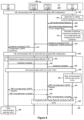
- FIGS. 3 A and 3 B are messaging diagrams of example scenarios in which a RAN prepares a DAPS handover procedure for a UE by releasing M of N cells via which the UE communicates with a source base station of the RAN prior to the UE performing DAPS handover to a target base station of the RAN;
- FIGS. 3 C through 3 E are messaging diagrams of example scenarios in which a RAN prepares a DAPS handover procedure for a UE by providing full or delta configurations to the UE prior to the UE performing DAPS handover to a target base station of the RAN;
- FIGS. 4 A and 4 B are messaging diagrams of example scenarios in which a RAN prepares a DAPS handover procedure for a UE by releasing a source SN of the RAN prior to the UE performing DAPS handover to a target SN of the RAN;
- FIG. 5 is a messaging diagram of an example scenario in which a RAN prepares a DAPS handover procedure for a UE by releasing M of N cells via which the UE communicates with a base station of the RAN prior to the UE performing DAPS handover to a target cell of the base station;
- FIG. 6 is a messaging diagram of an example scenario in which a RAN prepares a DAPS handover procedure for a UE by configuring a target pair of bandwidth parts of a target cell that does not overlap with a source pair of bandwidth parts of a source cell via which the UE communicates with a source base station of the RAN prior to the UE performing DAPS handover to the target cell of a target base station;
- FIG. 7 is a messaging diagram of an example scenario in which a RAN prepares a DAPS handover procedure for a UE by configuring a target pair of bandwidth parts of a target cell that does not overlap with a source pair of bandwidth parts of a source cell via which the UE communicates with base station of the RAN prior to the UE performing DAPS handover to the target cell of the base station;
- FIG. 8 is a messaging diagram of an example scenario in which a RAN prepares a UE to perform DAPS handover, from a source DU of a base station of the RAN to a target DU of a base station;
- FIGS. 9 A and 9 B are messaging diagrams of example scenarios in which a RAN configures a UE to release (or otherwise set as available) a MAC entity after performing DAPS handover;
- FIGS. 10 A and 10 B are messaging diagrams of example scenarios in which an MN of the RAN initiates a DAPS PSCell change procedure for a UE, from a source SN to a target SN;
- FIGS. 11 A and 11 B are messaging diagrams of example scenarios in which a source SN of the RAN initiates a DAPS PSCell change procedure for a UE, from the source SN to a target SN;
- FIGS. 12 A and 12 B are messaging diagrams of example scenarios in which an SN of the RAN initiates a DAPS PSCell change procedure for a UE, from a source cell of the SN to a target cell of the SN;
- FIGS. 13 A and 13 B are messaging diagrams of example scenarios in which a RAN prepares a DAPS PSCell change procedure for a UE by configuring a target pair of bandwidth parts of a target cell that does not overlap with a source pair of bandwidth parts of a source cell via which the UE communicates prior to the UE performing DAPS PSCell change to the target cell;
- FIG. 14 is a messaging diagram of an example scenario in which a RAN prepares a UE to perform DAPS PSCell change, from a source DU of a base station of the RAN to a target DU of the base station;
- FIGS. 15 A and 15 B are messaging diagrams of example scenarios in which a RAN configures a UE to release (or otherwise set as available) a MAC entity after performing DAPS PSCell change;
- FIGS. 16 A and 16 B are flow diagrams depicting example methods for configuring a UE to release cells and release an SN, respectively, to prepare the UE to perform DAPS handover to a target base station;
- FIGS. 17 A and 17 B are flow diagrams depicting example methods for preparing a UE to perform DAPS PSCell change involving an SN change and to perform DAPS PSCell change that does not involve an SN change, respectively;
- FIGS. 18 A and 18 B are flow diagrams depicting example methods for preparing a UE to perform DAPS handover, from a first pair of bandwidth parts (BWPs) of a first cell to a second pair of BWPs of a second cell;
- BWPs bandwidth parts
- FIGS. 19 A and 19 B are flow diagrams depicting example methods for preparing a UE to perform DAPS PSCell change, from a first pair of BWPs of a first cell to a second pair of BWPs of a second cell;
- FIG. 20 is a flow diagram depicting an example method for releasing a MAC entity after performing a DAPS handover, from a source base station to a target base station;
- FIG. 21 is a flow diagram depicting an example method for releasing a MAC entity after performing a DAPS PSCell change, from a first cell of a source SN to a second cell of a target SN;
- FIG. 22 is a flow diagram depicting an example method for preparing a UE to perform DAPS handover, from a source DU of a base station to a target DU of the base station;
- FIG. 23 is a flow diagram depicting an example method for preparing a UE to perform DAPS PSCell change, from a source DU of a base station to a target DU of the base station;
- FIG. 24 is a flow diagram depicting an example method in a RAN for enabling execution of a DAPS procedure at a UE;
- FIG. 25 is a flow diagram depicting an example method in a UE for executing of a DAPS procedure
- FIG. 26 is a flow diagram depicting an example method in a RAN for configuring a DAPS procedure at a UE communicating with the RAN using a first uplink bandwidth part (BWP) and a first downlink BWP of a source cell;
- BWP bandwidth part
- FIG. 27 is a flow diagram depicting an example method in a central unit (CU) of a distributed base station for configuring a DAPS procedure at a UE communicating with the distributed base station via a source distributed unit (DU); and
- CU central unit
- DU source distributed unit
- FIG. 28 is a flow diagram depicting an example method in a UE for managing connectivity.
- FIG. 1 A depicts an example wireless communication system 100 that can implement DAPS operation techniques of this disclosure.
- the wireless communication system 100 includes a UE 102 , as well as base stations 104 , 106 A, 106 B that are connected to a core network (CN) 110 .
- the base stations 104 , 106 A, 106 B can be any suitable type, or types, of base stations, such as an evolved node B (eNB), a next-generation eNB (ng-eNB), or a 5G Node B (gNB), for example.
- eNB evolved node B
- ng-eNB next-generation eNB
- gNB 5G Node B
- the base station 104 can be an eNB or a gNB
- the base stations 106 A and 106 B can be gNBs.
- the base station 104 supports a cell 124
- the base station 106 A supports a cell 126 A
- the base station 106 B supports a cell 126 B.
- the cell 124 partially overlaps with both of cells 126 A and 126 B, such that the UE 102 can be in range to communicate with base station 104 while simultaneously being in range to communicate with base station 106 A or 106 B (or in range to detect or measure the signal from both base stations 106 A or 106 B, etc.).
- the overlap can make it possible for the UE 102 to hand over between cells (e.g., from cell 124 to cell 126 A or 126 B) or base stations (e.g., from base station 104 to base station 106 A or base station 106 B) before the UE 102 experiences radio link failure, for example.
- the overlap allows the various dual connectivity (DC) scenarios discussed below.
- the UE 102 can communicate in DC with the base station 104 (operating as an MN) and the base station 106 A (operating as an SN) and, upon completing a handover, can communicate with the base station 106 B (operating as an MN).
- the UE 102 can communicate in DC with the base station 104 (operating as an MN) and the base station 106 A (operating as an SN) and, upon completing an SN change, can communicate with the base station 104 (operating as an MN) and the base station 106 B (operating as an SN).
- the base station 104 when the UE 102 is in DC with the base station 104 and the base station 106 A, the base station 104 operates as a master eNB (MeNB), a master ng-eNB (Mng-eNB), or a master gNB (MgNB), and the base station 106 A operates as a secondary gNB (SgNB) or a secondary ng-eNB (Sng-eNB).
- MeNB master eNB
- Mng-eNB master ng-eNB
- MgNB master gNB
- SgNB secondary gNB
- Sng-eNB secondary ng-eNB
- the base station 104 operates as an MeNB, an Mng-eNB or an MgNB
- the base station 106 A operates as a candidate SgNB (C-SgNB) or a candidate Sng-eNB (C-Sng-eNB).
- C-SgNB candidate SgNB
- C-Sng-eNB candidate Sng-eNB
- any of the base stations 104 , 106 A, 106 B generally can operate as an MN, an SN or a T-SN in different scenarios.
- the base station 104 , the base station 106 A, and the base station 106 B can implement similar sets of functions and each support MN, SN, and T-SN operations.
- the UE 102 can use a radio bearer (e.g., a DRB or an SRB) that at different times terminates at an MN (e.g., the base station 104 ) or an SN (e.g., the base station 106 A).
- a radio bearer e.g., a DRB or an SRB
- the UE 102 can apply one or more security keys when communicating on the radio bearer, in the uplink (from the UE 102 to a base station) and/or downlink (from a base station to the UE 102 ) direction.
- the base station 104 includes processing hardware 130 , which can include one or more general-purpose processors (e.g., central processing units (CPUs) and a computer-readable memory storing machine-readable instructions executable on the one or more general-purpose processor(s), and/or special-purpose processing units.
- the processing hardware 130 in the example implementation in FIG. 1 A includes a base station RRC controller 132 that is configured to manage or control RRC configurations and RRC procedures.
- the base station RRC controller 132 can be configured to support RRC messaging associated with DAPS handover and DAPS PSCell change procedures, and/or to support the necessary operations when the base station 104 operates as an MN, as discussed below.
- the base station 106 A includes processing hardware 140 , which can include one or more general-purpose processors (e.g., CPUs) and a computer-readable memory storing machine-readable instructions executable on the general-purpose processor(s), and/or special-purpose processing units.
- the processing hardware 140 in the example implementation of FIG. 1 A includes a base station RRC controller 142 that is configured to manage or control RRC configurations and RRC procedures.
- the base station RRC controller 142 can be configured to support RRC messaging associated with DAPS handover and DAPS PSCell change procedures, and/or to support the necessary operations when the base station 106 A operates as an SN or target SN (T-SN), as discussed below.
- the base station 106 B can include processing hardware similar to the processing hardware 140 of the base station 106 A.
- the UE 102 includes processing hardware 150 , which can include one or more general-purpose processors (e.g., CPUs) and a computer-readable memory storing machine-readable instructions executable on the general-purpose processor(s), and/or special-purpose processing units.
- the processing hardware 150 in the example implementation of FIG. 1 A includes a UE RRC controller 152 that is configured to manage or control RRC configurations RRC procedures.
- the UE RRC controller 152 can be configured to support RRC messaging associated with DAPS handover and DAPS PSCell change procedures in accordance with any of the implementations discussed below.
- the CN 110 can be an evolved packet core (EPC) 111 or a fifth-generation core (5GC) 160 , both of which are depicted in FIG. 1 A .
- the base station 104 can be an eNB supporting an S1 interface for communicating with the EPC 111 , an ng-eNB supporting an NG interface for communicating with the 5GC 160 , or as a gNB that supports the NR radio interface as well as an NG interface for communicating with the 5GC 160 .
- the base station 106 A can be an EN-DC gNB (en-gNB) with an S1 interface to the EPC 111 , an en-gNB that does not connect to the EPC 111 , a gNB that supports the NR radio interface and an NG interface to the 5GC 160 , or a ng-eNB that supports an EUTRA radio interface and an NG interface to the 5GC 160 .
- en-gNB EN-DC gNB
- a gNB that supports the NR radio interface and an NG interface to the 5GC 160
- a ng-eNB that supports an EUTRA radio interface and an NG interface to the 5GC 160 .
- the base stations 104 , 106 A, and 106 B can support an X2 or Xn interface.
- the EPC 111 can include a Serving Gateway (S-GW) 112 and a Mobility Management Entity (MME) 114 .
- S-GW 112 is generally configured to transfer user-plane packets related to audio calls, video calls, Internet traffic, etc.
- MME 114 is configured to manage authentication, registration, paging, and other related functions.
- the 5GC 160 includes a User Plane Function (UPF) 162 and an Access and Mobility Management (AMF) 164 , and/or Session Management Function (SMF) 166 .
- UPF User Plane Function
- AMF Access and Mobility Management
- SMF Session Management Function
- the UPF 162 is generally configured to transfer user-plane packets related to audio calls, video calls, Internet traffic, etc.
- the AMF 164 is configured to manage authentication, registration, paging, and other related functions
- the SMF 166 is configured to manage PDU sessions.
- the wireless communication network 100 can include any suitable number of base stations supporting NR cells and/or EUTRA cells.
- base station 104 and base station 106 A can also support cells 122 and 123 , respectively.
- the EPC 111 or the 5GC 160 can be connected to any suitable number of base stations supporting NR cells and/or EUTRA cells.
- the examples below refer specifically to specific CN types (EPC, 5GC) and RAT types (5G NR and EUTRA)
- 6G sixth generation
- 6G core network 5G NR-6G DC
- the wireless communication system 100 can support various procedures (e.g., DAPS handover, DAPS PSCell change, etc.) and modes of operation (e.g., SC or DC). Example operation of various procedures that can be implemented in the wireless communication system 100 will now be described.
- the wireless communication system 100 supports a legacy handover preparation procedure (i.e., a non-DAPS handover preparation procedure).
- the base station 104 can perform a non-DAPS handover preparation procedure to configure the UE 102 to handover from a cell 124 of the base station 104 to a cell 126 A of the base station 106 A.
- the base station 104 and the base station 106 A operate as a source base station (S-BS) or a source MN (S-MN), and a target base station (T-BS) or a target MN (T-MN), respectively.
- S-BS source base station
- S-MN source MN
- T-BS target base station
- T-MN target MN
- the base station 104 sends a Handover Request message to the base station 106 A.
- the base station 106 A includes configuration parameters configuring radio resources for the UE 102 in a handover command message, includes the handover command message in a Handover Request Acknowledge message, and sends the Handover Request Acknowledge message to the base station 104 .
- the base station 104 transmits the handover command message to the UE 102 and subsequently discontinues (or stops) transmitting data to or receiving data from the UE 102 .
- the UE 102 Upon receiving the handover command message, the UE 102 hands over to the base station 106 A via cell 126 A and communicates with the base station 106 A by using the configuration parameters in the handover command message. Particularly, in response to the handover command message, the UE 102 disconnects from the cell 124 (or the base station 104 ), performs a random access procedure with the base station 106 A via the cell 126 A, and transmits a handover complete message to the base station 106 A via the cell 126 A.
- the wireless communication system 100 supports a DAPS handover preparation procedure.
- the base station 104 can perform a DAPS handover preparation procedure to configure the UE 102 to hand over from a cell 124 of the base station 104 to a cell 126 B of the base station 106 B.
- the base station 104 and the base station 106 B operate as an S-BS or an S-MN, and a T-BS or a T-MN, respectively.
- the base station 104 sends a Handover Request message to the base station 106 B.
- the base station 104 can explicitly request DAPS handover in the Handover Request message, e.g., by including a DAPS indicator in the Handover Request message.
- the base station 106 B includes configuration parameters configuring radio resources for the UE 102 in a handover command, includes the handover command message in a Handover Request Acknowledge message, and sends the Handover Request Acknowledge message to the base station 104 .
- the base station 106 B can indicate DAPS handover in the handover command message, e.g., by including a DAPS handover configuration or a DAPS handover indicator in the handover command message, or can include an indicator in the Handover Request Acknowledge message.
- the base station 104 transmits the handover command message to the UE 102 .
- the UE 102 Upon receiving the handover command message, the UE 102 hands over to the base station 106 B via cell 126 B and communicates with the base station 106 B by using the configuration parameters in the handover command message. Particularly, in response to the handover command message, whereas in the non-DAPS handover preparation procedure the UE 102 disconnects from the cell 124 (or the base station 104 ), the UE 102 in the DAPS handover preparation procedure maintains the connection to the base station 104 via cell 124 , performs a random access procedure with the base station 106 B via cell 126 B, and transmits a handover complete message to the base station 106 B via cell 126 B.
- the UE 102 In maintaining the connection to the base station 104 via cell 124 in the DAPS handover preparation procedure, the UE 102 effectively has two links, i.e., a source MCG link with the base station 104 and a target MCG link with the base station 106 B.
- the UE 102 can continue receiving data (i.e., downlink data) from the base station 104 until the UE 102 receives an indication from the base station 106 B to release the source MCG link with the base station 104 .
- the UE 102 can continue transmitting data (e.g., new uplink data transmission or retransmission of PDCP SDUs) to the base station 104 until the UE 102 either successfully completes the random access procedure with the base station 106 B or receives the indication from the base station 106 B to release the MCG link with the base station 104 .
- data e.g., new uplink data transmission or retransmission of PDCP SDUs
- the wireless communication system 100 supports DC operation.
- the base station 104 can perform an SN addition procedure to add the base station 106 A as an SN, thereby configuring the UE 102 to operate in DC with the base stations 104 and 106 A.
- the base stations 104 and 106 A operate as an MN and an SN, respectively.
- the MN 104 can initiate the non-DAPS or DAPS handover preparation procedures to handover the UE 102 to the T-MN 106 B.
- the wireless communication system 100 supports a legacy PSCell change preparation procedure (i.e., a non-DAPS PSCell change preparation procedure).
- the UE 102 is initially in DC with the MN 104 (e.g., via PCell 124 ) and the SN 106 A (via a PSCell 123 ).
- the SN 106 A can provide a configuration for the T-PSCell 126 A, for the UE 102 .
- the UE 102 stops communicating with the SN 106 A via PSCell 123 and attempts to connect to the T-PSCell 126 A after receiving the configuration for the T-PSCell 126 A.
- the MN 104 determines to change the SN of the UE 102 from the base station 106 A (which may be referred to as the source SN or S-SN) to the base station 106 B (which may be referred to as the target SN or T-SN) as part of the non-DAPS PSCell change procedure.
- the UE 102 stops communicating with the S-SN 106 A via PSCell 123 and attempts to connect to the T-SN 106 B via T-PSCell 126 B after receiving the configuration for the T-PSCell 126 B.
- the wireless communication system 100 supports DAPS PSCell change.
- the UE 102 is initially in DC with the MN 104 (e.g., via PCell 124 ) and the SN 106 A (via a PSCell 123 ).
- the SN 106 A can provide a configuration for the T-PSCell 126 A, for the UE 102 .
- the UE 102 continues communicating with the SN 106 A via PSCell 123 while attempting to connect to the T-PSCell 126 A after receiving the configuration for the T-PSCell 126 A.
- the UE 102 stops communicating with the SN 106 A via PSCell 123 .
- the MN 104 determines to change the SN of the UE 102 from the base station 106 A (which may be referred to as the source SN or S-SN) to the base station 106 B (which may be referred to as the target SN or T-SN) as part of the DAPS PSCell change procedure.
- the UE 102 continues communicating with the S-SN 106 A via PSCell 123 while attempting to connect to the T-SN 106 B via T-PSCell 126 B after receiving the configuration for the T-PSCell 126 B. After the T-PSCell 126 B begins to operate as the PSCell 126 B for the UE 102 , the UE 102 stops communicating with the S-SN 106 A via PSCell 123 .
- the base station 104 can operate as an MeNB, an Mng-eNB, or an MgNB
- the base station 106 B can operate as an MeNB, an Mng-eNB, an MgNB, an SgNB, or an Sng-eNB
- the base station 106 A can operate as an SgNB or an Sng-eNB.
- the UE 102 can communicate with the base station 104 and the base station 106 A or 106 B via the same radio access technology (RAT), such as EUTRA or NR, or via different RATs.
- RAT radio access technology
- the UE 102 can be in EUTRA-NR DC (EN-DC) with the MeNB 104 and the SgNB 106 A.
- the UE 102 can be in next generation (NG) EUTRA-NR DC (NGEN-DC) with the Mng-eNB 104 and the SgNB 106 A.
- the base station 104 is an MgNB and the base station 106 A is an SgNB
- the UE 102 can be in NR-NR DC (NR-DC) with the MgNB 104 and the SgNB 106 A.
- NR-DC NR-NR DC
- the base station 104 is an MgNB and the base station 106 A is an Sng-eNB
- the UE 102 can be in NR-EUTRA DC (NE-DC) with the MgNB 104 and the Sng-eNB 106 A.
- FIG. 1 B depicts an example, distributed implementation of any one or more of the base stations 104 , 106 A, 106 B.
- the base station 104 , 106 A, or 106 B includes a centralized unit (CU) 172 and one or more distributed units (DUs) 174 .
- the CU 172 includes processing hardware, such as one or more general-purpose processors (e.g., CPUs) and a computer-readable memory storing machine-readable instructions executable on the general-purpose processor(s), and/or special-purpose processing units.
- the CU 172 can include the processing hardware 130 or 140 of FIG. 1 A .
- the processing hardware can include a base station RRC controller (e.g., RRC controller 142 ) configured to manage or control one or more RRC configurations and/or RRC procedures when the base station (e.g., base station 106 A) operates as an SN.
- a base station RRC controller e.g., RRC controller 142
- RRC controller 142 configured to manage or control one or more RRC configurations and/or RRC procedures when the base station (e.g., base station 106 A) operates as an SN.
- Each of the DUs 174 also includes processing hardware that can include one or more general-purpose processors (e.g., CPUs) and computer-readable memory storing machine-readable instructions executable on the one or more general-purpose processors, and/or special-purpose processing units.
- the processing hardware can include a medium access control (MAC) controller configured to manage or control one or more MAC operations or procedures (e.g., a random access procedure), and a radio link control (RLC) controller configured to manage or control one or more RLC operations or procedures when the base station (e.g., base station 106 A) operates as a MN or an SN.
- the process hardware can also include a physical layer controller configured to manage or control one or more physical layer operations or procedures.
- FIG. 2 illustrates, in a simplified manner, an example dual active protocol stack (DAPS) 200 according to which the UE 102 can communicate with an eNB/ng-eNB or a gNB (e.g., one or more of the base stations 104 , 106 A, 106 B).
- DAPS dual active protocol stack
- a physical layer (PHY) 202 A of EUTRA provides transport channels to the EUTRA MAC sublayer 204 A, which in turn provides logical channels to the EUTRA RLC sublayer 206 A.
- the EUTRA RLC sublayer 206 A in turn provides RLC channels to the EUTRA PDCP sublayer 208 and, in some cases, to the NR PDCP sublayer 210 .
- the NR PHY 202 B provides transport channels to the NR MAC sublayer 204 B, which in turn provides logical channels to the NR RLC sublayer 206 B.
- the NR RLC sublayer 206 B in turn provides RLC channels to the NR PDCP sublayer 210 .
- the UE 102 supports both the EUTRA and the NR stack as shown in FIG. 2 , to support handover between EUTRA and NR base stations and/or to support DC over EUTRA and NR interfaces. Further, as illustrated in FIG. 2 , the UE 102 can support layering of NR PDCP 210 over EUTRA RLC 206 A.
- the EUTRA PDCP sublayer 208 and the NR PDCP sublayer 210 receive packets (e.g., from an Internet Protocol (IP) layer, layered directly or indirectly over the PDCP layer 208 or 210 ) that can be referred to as service data units (SDUs), and output packets (e.g., to the RLC layer 206 A or 206 B) that can be referred to as protocol data units (PDUs). Except where the difference between SDUs and PDUs is relevant, this disclosure for simplicity refers to both SDUs and PDUs as “packets.”
- IP Internet Protocol
- PDUs protocol data units
- the EUTRA PDCP sublayer 208 and the NR PDCP sublayer 210 can provide SRBs to exchange RRC messages, for example.
- the EUTRA PDCP sublayer 208 and the NR PDCP sublayer 210 can provide DRBs to support data exchange.
- the wireless communication system 100 can provide the UE 102 with an MN-terminated bearer that uses EUTRA PDCP sublayer 208 , or an MN-terminated bearer that uses NR PDCP sublayer 210 .
- the wireless communication system 100 in various scenarios can also provide the UE 102 with an SN-terminated bearer, which uses only the NR PDCP sublayer 210 .
- the MN-terminated bearer can be an MCG bearer or a split bearer.
- the SN-terminated bearer can be an SCG bearer or a split bearer.
- the MN-terminated bearer can be an SRB (e.g., SRB1 or SRB2) or a DRB.
- the SN-terminated bearer can be an SRB or a DRB.
- FIGS. 3 through 15 illustrate message sequences between the UE 102 and various base stations of the RAN (including base stations 104 , 106 A and/or 106 B), for a number of scenarios and implementations relating to DAPS handover and DAPS PSCell change procedures.
- FIG. 3 i.e., 3 A through 3 E
- FIG. 9 i.e., 9 A and 9 B
- FIG. 10 i.e., 10 A and 10 B
- FIG. 15 i.e., 15 A and 15 B
- FIG. 10 correspond to DAPS PSCell change scenarios in which a base station initiates a DAPS PSCell change procedure for a UE.
- the base station 104 operates as a source base station (S-BS) for the UE 102
- the base station 106 B operates as a target base station (T-BS).
- the UE 102 communicates 302 A data (e.g., uplink (UL) data PDUs and/or downlink (DL) data PDUs) with the S-BS 104 via N cells using carrier aggregation (CA), where N is a whole number greater than one, by using an S-BS configuration.
- the N cells include PCell 124 and one or more secondary cells (SCells), such as cell 122 .
- the UE 102 communicates 302 A data in SC with the S-BS 104 , or communicates 302 A data in DC with the S-BS 104 operating as an MN and an SN (e.g., the base station 106 A) not shown in FIG. 3 A .
- the S-BS 104 determines 304 A to initiate DAPS handover for the T-BS 106 B and the UE 102 to communicate, e.g., blindly or in response to detecting a suitable event.
- the determination 304 A can occur in response to the S-BS 104 receiving one or more measurement results from the UE 102 that are above (or below) one or more predetermined thresholds, or calculating a filtered result (from the measurement result(s)) that is above (or below) a predetermined threshold.
- the suitable event can be that the UE 102 is moving toward the T-BS 106 B.
- the suitable event can be one or more measurement results, generated or obtained by the S-BS 104 based on measurements of signals received from the UE 102 , being above (or below) one or more predetermined thresholds.
- the S-BS 104 transmits 306 A an RRC reconfiguration message to the UE 102 to configure the UE 102 to release M cells, where M is a whole number less than N (i.e., 0 ⁇ M ⁇ N).
- the M cells can be one, some, or all of the SCells covered by the S-BS 104 .
- the UE 102 releases 308 A the M cells (i.e., the UE 102 disconnects from the M cells).
- RF chain(s) or transceiver(s) of the UE 102 that were previously operating in communicating with the S-BS 104 via the M cells become available for use to communicate with the T-BS 106 B during and after a successful DAPS handover, while those that are communicating with the S-BS 104 via the N-M cells are still in use.
- the UE 102 and the S-BS 104 update the S-BS configuration by excluding configurations relevant to the released M cells, and continue 309 A communicating with each other (i.e., via N-M cells) by using the updated S-BS configuration.
- the UE 102 and the S-BS 104 can update the S-BS configuration accordingly.
- the UE 102 then transmits 310 A an RRC reconfiguration complete message to the S-BS 104 .
- events 306 A, 308 A, 309 A, and 310 A may be omitted.
- the S-BS 104 After determining 304 A to initiate DAPS handover, the S-BS 104 also sends 312 A a Handover Request message to the T-BS 106 B.
- the T-BS 106 B generates 314 A a handover command message that includes a DAPS handover configuration or an indication for the DAPS handover configuration in a field or an IE (e.g., a dapsConfig field, a dapsHO-Config field, a daps-HO field or a daps-HO-Config field), includes the handover command message in a Handover Request Acknowledge message, and sends 316 A the Handover Request Acknowledge message to the S-BS 104 .
- IE e.g., a dapsConfig field, a dapsHO-Config field, a daps-HO field or a daps-HO-Config field
- the S-BS 104 transmits 318 A the handover command message to the UE 102 .
- the handover command message also includes one or more random access configurations needed by the UE 102 to handover to the T-BS 106 B, and in some implementations, includes additional fields, such as a mobility field (e.g., mobilityControlInfo field or a reconfigurationWithSync field), which can include some or all of the random access configurations.
- a mobility field e.g., mobilityControlInfo field or a reconfigurationWithSync field
- the DAPS handover configuration enables the UE 102 to use a DAPS (e.g., DAPS 200 ) to communicate with the S-BS 104 (using the updated S-BS configuration) and T-BS 106 B (during and after a successful DAPS handover).
- a DAPS e.g., DAPS 200
- the UE 102 and the S-BS 104 continue 320 A communicating with each other using the updated S-BS configuration while the UE 102 attempts to handover to the T-BS 106 B in accordance with the handover command message.
- the UE 102 In attempting to perform the DAPS handover, the UE 102 initiates 322 A a random access procedure with the T-BS 106 B via a target cell (e.g., PCell 126 B) covered by the T-BS 106 B, e.g., by using one or more random access configurations in the handover command message received 318 A from the S-BS 104 . After gaining access to a channel, the UE 102 transmits 324 A a handover complete message to the T-BS 106 B via the target cell during or after successfully completing the random access procedure.
- a target cell e.g., PCell 126 B
- the UE 102 After gaining access to a channel, the UE 102 transmits 324 A a handover complete message to the T-BS 106 B via the target cell during or after successfully completing the random access procedure.
- the UE 102 After the T-BS 106 B identifies the UE 102 during the random access procedure, the UE 102 communicates 326 A control signals and data (e.g., UL data PDUs or DL data PDUs) with the T-BS 106 B via the target cell by using the DAPS handover configuration in or otherwise indicated in the handover command message.
- the DAPS handover configuration enables the UE 102 to continue communicating with the S-BS 104 while simultaneously communicating with the T-BS 106 B.
- the T-BS 106 B In response to identifying the UE 102 during the random access procedure or receiving 324 A the handover complete message, the T-BS 106 B sends 328 A a Handover Success message to the S-BS 104 . After receiving the Handover Success message, the S-BS 104 stops 330 A communicating with the UE 102 . In some implementations, the S-BS 104 can transmit a sequence number (SN) Status Transfer message to the T-BS 106 B in response to the Handover Success message. In some implementations, before or after transmitting the Handover Success message, the T-BS 106 B can send an explicit stop indication message to the S-BS 104 , which in turn can stop 330 A communicating with the UE 102 in response to the explicit stop indication.
- SN sequence number
- the S-BS 104 stops 330 A communicating with the UE 102 in response to generating the SN Status Transfer message.
- the T-BS 106 B can send a Context Release message to the S-BS 104 to release a UE Context of the UE 102 .
- the T-BS 106 B can send 332 A an RRC reconfiguration message that includes a DAPS release indicator to the UE 102 , e.g., via the target cell, before transmitting 328 A the Handover Success message, after transmitting 328 A the Handover Success message, or simultaneously with the Handover Success message.
- the UE 102 can transmit 334 A an RRC reconfiguration complete message to the T-BS 106 B and stop 336 A communicating (i.e., UL and/or DL communication) with the S-BS 104 .
- a RF chip, receiver, or a transceiver of the UE 102 used to communicate with the S-BS 104 during the DAPS handover can enter into low power consumption mode, sleep mode, or be turned off entirely if the DAPS handover is an inter-frequency handover.
- the events 322 A, 324 A, 326 A, 328 A, 330 A, 332 A, 334 A are collectively referred to in FIG. 3 A as the DAPS handover and DAPS release procedure 350 A.
- the S-BS 104 determines to configure the UE 102 to release M cells according to a DAPS handover capability in a UE Capability information element (IE) of a message (e.g., in a UECapabilityInformation message) received from the UE 102 , the CN 110 (e.g., via a S1 or NG interface message), or another base station (e.g., the base station 106 A, the base station 106 B, or other base station not shown in FIG. 1 A ) via an X2 or Xn interface.
- IE UE Capability information element
- the S-BS 104 can include the UE Capability IE in the Handover Request message in event 312 A so that the T-BS 106 B is aware of the DAPS handover capability of the UE 102 .
- the UE Capability IE can be a UE-NR-Capability IE as defined in 3GPP TS 38.331 or a UE-EUTRA-Capability IE as defined in 3GPP TS 36.331.
- the S-BS 104 can configure the UE 102 to release all SCells (i.e., N ⁇ 1 SCells).
- the DAPS handover capability indicates that the UE 102 is capable of communicating with the S-BS 104 using CA in N-P cells associated to one or more particular frequency bands during DAPS handover, where P is a whole number greater than or equal to 0 and less than or equal to M (i.e., 0 ⁇ P ⁇ M)
- the S-BS 104 can configure the UE 102 to release M cells if N-M cells are associated to some or all of the one or more particular frequency bands.
- the S-BS 104 can perform a non-DAPS handover preparation procedure with the T-BS 106 B.
- the T-BS 106 B instead of generating the handover command message that includes the DAPS handover configuration (or an indication for the DAPS handover configuration) at event 314 A, the T-BS 106 B generates a handover command message that excludes the DAPS handover configuration (or the indication for the DAPS handover configuration).
- the S-BS 104 determines to configure the UE 102 to release N ⁇ 1 cells if the S-BS 104 is unaware whether the UE 102 is capable of DAPS handover with CA. The S-BS 104 can ensure that the UE 102 can perform DAPS handover by releasing the N ⁇ 1 cells.
- the DAPS handover capability indicates that the UE 102 is capable of inter-frequency DAPS handover for one or more frequency bands.
- the DAPS handover capability can further specify that the UE 102 is capable of inter-frequency DAPS handover for frequency division duplex (FDD) and/or time division duplex (TDD) mode, using one or more indicators included in the DAPS handover capability.
- the UE Capability IE can specify that the UE 102 is capable of inter-frequency DAPS handover for FDD and/or TDD mode, using an inter-frequency handover capability field/IE included in the UE Capability IE.
- the S-BS 104 or T-BS 106 B can determine whether the UE 102 is capable of inter-frequency DAPS handover for one or more frequency bands, and if further specified, for FDD and/or TDD mode, according to the DAPS handover capability and/or the UE Capability IE. If the UE Capability IE does not include the DAPS handover capability, irrespective of including the inter-frequency handover capability field/IE, the S-BS 104 or T-BS 106 B determines that the UE 102 is capable of the inter-frequency non-DAPS handover.
- the UE Capability IE includes DC/CA band combination field(s)/IE(s) to indicate that the UE 102 is capable of performing CA on one or more bands (e.g., FDD band(s) only, TDD band(s) only, FDD band(s) and TDD band(s)).
- the CA band combination field(s)/IE(s) can designate respective CA band combination(s) (e.g., a first CA band combination and a second CA band combination), each CA band combination indicating the band(s).
- the DAPS handover capability can be included in the CA band combination field(s)/IE(s) to indicate that the UE 102 is capable of the inter-frequency DAPS handover associated to the CA band combination(s) indicated in the CA band combination field(s)/IE(s).
- support of the DAPS handover can be on a per CA band combination basis. For example, if the UE 102 supports DAPS handover associated to a first CA band combination but not a second CA band combination, the UE 102 includes the DAPS handover capability in a first CA band combination field/IE designating the first CA band combination, and excludes the DAPS handover capability in a second CA band combination field/IE designating the second CA band combination. Therefore, the S-BS 104 or T-BS 106 B can determine whether the UE 102 is capable of inter-frequency DAPS handover according to the DAPS handover capability and the CA band combination field(s)/IE(s).
- cell 124 operates on a first DL carrier frequency and a first UL carrier frequency
- cell 126 B operates on a second DL carrier frequency and a second UL carrier frequency.
- Cells 124 and 126 B can be either FDD cells or TDD cells.
- the first DL carrier frequency and the first UL carrier frequency belong to a TDD band (i.e., the cell 124 is a TDD cell)
- the first DL carrier frequency and the first UL carrier frequency are the same or overlapped carrier frequencies.
- the first DL carrier frequency and the first UL carrier frequency belong to an FDD band (i.e., the cell 124 is an FDD cell)
- the DL carrier frequency and the UL carrier frequency are different carrier frequencies.
- the second DL carrier frequency and the second UL carrier frequency belong to a TDD band (i.e., the cell 126 B is a TDD cell), the second DL carrier frequency and the second UL carrier frequency are the same carrier frequency. If the second DL carrier frequency and the second UL carrier frequency belong to an FDD band (i.e., the cell 126 B is an FDD cell), the second DL carrier frequency and the second UL carrier frequency are different carrier frequencies. If the UE 102 is capable of the inter-frequency DAPS handover, the S-BS 104 requests the T-BS 106 B to configure cell 126 B in the Handover Request message for the inter-frequency DAPS handover, and the T-BS 106 B configures the cell 126 B in the handover command message.
- the S-BS 104 requests the T-BS 106 B to configure cell 126 B in the Handover Request message for the inter-frequency non-DAPS handover, and the T-BS 106 B configures the cell 126 B in the handover command message.
- the DAPS handover capability indicates that the UE 102 is capable of FDD-TDD DAPS handover (i.e., DAPS handover from an FDD cell to a TDD cell and/or vice versa).
- the DAPS handover capability can further specify that the UE 102 is capable of FDD-TDD DAPS handover using one or more indicators included in the DAPS handover capability.
- the DAPS handover capability can include a single indicator indicating that the UE 102 is capable of FDD-TDD DAPS handover from an FDD cell (in a specific or any FDD band supported by the UE 102 ) to a TDD cell (in a specific or any TDD band supported by the UE 102 ), and/or vice versa.
- an FDD-TDD handover capability field/IE included in the UE Capability IE can indicate that the UE 102 is capable of the FDD-TDD DAPS handover.
- the S-BS 104 or T-BS 106 can determine whether the UE 102 is capable of FDD-TDD DAPS handover according to the DAPS handover capability and/or the FDD-TDD handover capability field/IE. If the UE Capability IE does not include the DAPS handover capability, irrespective of including the FDD-TDD handover capability field/IE, the S-BS 104 or T-BS 106 determines that the UE 102 is capable of the FDD-TDD non-DAPS handover.
- one of the cells 124 and 126 B is a TDD cell, and the other is an FDD cell. If the UE 102 is capable of the FDD-TDD DAPS handover, the S-BS 104 requests the T-BS 106 B to configure cell 126 B in the Handover Request message for the FDD-TDD DAPS handover, and the T-BS 106 B configures the cell 126 B in the handover command message.
- the S-BS 104 requests the T-BS 106 B to configure cell 126 B in the Handover Request message for the FDD-TDD non-DAPS handover, and the T-BS 106 B configures the cell 126 B in the handover command message.
- the DAPS handover capability indicates that the UE 102 is capable of intra-frequency DAPS handover for one or more frequency bands.
- the UE Capability IE can specify that the UE 102 is capable of intra-frequency DAPS handover, using an indication included in the UE Capability IE. Therefore, the S-BS 104 or T-BS 106 B can determine whether the UE 102 is capable of intra-frequency DAPS handover according to the DAPS handover capability and/or the UE Capability IE.
- the S-BS 104 or T-BS 106 determines that the UE 102 is capable of intra-frequency non-DAPS handover.
- the S-BS 104 or T-BS 106 B determines that the UE 102 is capable of the intra-frequency DAPS handover.
- cells 124 and 126 B are either TDD cells or FDD cells and operate on the same or overlapped carrier frequencies. If the UE 102 is capable of the intra-frequency DAPS handover, the S-BS 104 can request the T-BS 106 B to configure the cell 126 B in the Handover Request message for the intra-frequency DAPS handover, and the T-BS 106 B configures the cell 126 B in the handover command message.
- the S-BS 104 requests the T-BS 106 B to configure cell 126 B in the Handover Request message for the intra-frequency non-DAPS handover, and the T-BS 106 B configures the cell 126 B in the handover command message.
- the DAPS handover capability indicates that the UE 102 is capable of inter-RAT DAPS handover using one or more indicators.
- the DAPS handover capability can include a single indicator indicating that the UE 102 is capable of inter-RAT DAPS handover from a cell of a first RAT (or a cell in a specific band in the first RAT) to a cell of a second RAT (or a cell in a specific band in the second RAT).
- the UE Capability IE can specify that the UE 102 is capable of inter-RAT DAPS handover, using an inter-RAT handover capability field/IE included in the UE Capability IE that indicates that the UE 102 is capable of inter-RAT DAPS handover from a first RAT to a second RAT. Therefore, the S-BS 104 or T-BS 106 can determine whether the UE 102 is capable of inter-RAT DAPS handover according to the DAPS handover capability and/or the UE Capability IE.
- the S-BS 104 or T-BS 106 determines that the UE 102 is capable of the inter-RAT non-DAPS handover.
- cell 124 operates in the first RAT (e.g., EUTRA) and cell 126 B operates in the second RAT (e.g., NR).
- the S-BS 104 can request the T-BS 106 B to configure the cell 126 B in the Handover Request message for the inter-RAT DAPS handover, and the T-BS 106 B configures the cell 126 B in the handover command message.
- the S-BS 104 requests the T-BS 106 B to configure cell 126 B in the Handover Request message for the inter-RAT non-DAPS handover, and the T-BS 106 B configures the cell 126 B in the handover command message.
- the DAPS handover capability indicates that the UE 102 is capable of synchronous DAPS handover, asynchronous DAPS handover, or both, using one or more indicators.
- the DAPS handover capability can include a “synchronous” indicator or an “asynchronous” indicator indicating that the UE 102 is capable of synchronous or asynchronous DAPS handover, respectively.
- the DAPS handover capability can include the “synchronous” indicator indicating that the UE 102 is only capable of synchronous DAPS handover, or include the “asynchronous” indicator indicating that the UE 102 is capable of both synchronous DAPS handover and asynchronous DAPS handover.
- the “synchronous” and/or “asynchronous” indicators can be generic for or associated to all types of DAPS handover discussed above (e.g., intra-frequency DAPS handover, inter-frequency DAPS handover, FDD-TDD DAPS handover, and/or inter-RAT DAPS handover) that the UE 102 supports.
- the S-BS 104 can send a Handover Request message to the T-BS 106 B to request the T-BS 106 B to prepare non-DAPS handover for the UE 102 , and the T-BS 106 B can configure the non-DAPS handover in the handover command message, in one implementation.
- the S-BS 104 can send a Handover Request message to the T-BS 106 B to request the T-BS 106 B to prepare DAPS handover for the UE 102 , but the T-BS 106 B can still configure the non-DAPS handover in the handover command message, and optionally notify the S-BS 104 of the non-DAPS handover for the UE 102 . Otherwise, if the UE 102 supports asynchronous DAPS handover, the S-BS 104 can send a Handover Request message to the T-BS 106 B to request the T-BS 106 B to prepare DAPS handover for the UE 102 .
- the S-BS 104 determines that the T-BS 106 B is an asynchronous base station and subsequently requests the T-BS 106 B to prepare non-DAPS handover for a particular UE (e.g., UE 102 ) that only supports synchronous DAPS handover, and DAPS handover for a particular UE that only supports asynchronous DAPS handover.
- the T-BS 106 B determines that the S-BS 104 is an asynchronous base station and subsequently prepares non-DAPS handover for a particular UE that only supports synchronous DAPS handover, and DAPS handover for a particular UE that only supports asynchronous DAPS handover.
- the T-BS 106 B can determine whether the UE supports synchronous DAPS handover and/or asynchronous DAPS handover based on a DAPS capability in a UE Capability IE of the particular UE received from the S-BS 104 .
- the “synchronous” and/or “asynchronous” indicators can be specific for or associated to a particular type of DAPS handover discussed above that the UE 102 supports. For example, if the UE 102 supports inter-frequency DAPS handover and FDD-TDD DAPS handover, the UE 102 indicates first “synchronous” and/or “asynchronous” indicators for the inter-frequency DAPS handover and second “synchronous” and/or “asynchronous” indicators for the FDD-TDD DAPS handover.
- the S-BS 104 can send a Handover Request message to the T-BS 106 B to request the T-BS 106 B to prepare non-DAPS handover for the UE 102 , in one implementation.
- the S-BS 104 can send a Handover Request message to the T-BS 106 B to request the T-BS 106 B to prepare DAPS handover for the UE 102 , but the T-BS 106 B can still configure the non-DAPS handover in the handover command message, and optionally notify the S-BS 104 of the non-DAPS handover for the UE 102 .
- the RRC reconfiguration procedure i.e., events 306 A, 308 A, 309 A, 310 A
- the DAPS handover preparation procedure e.g., events 312 A, 314 A, 316 A
- the S-BS 104 sends 312 A the Handover Request message before or after transmitting 306 A the RRC reconfiguration message or receiving 310 A the RRC reconfiguration complete message, in one implementation.
- the S-BS 104 sends 312 A the Handover Request message and sends 306 A the RRC reconfiguration message at the same time.
- the UE 102 stops transmitting and retransmitting UL data PDUs and/or control signals on PUCCH(s) to the S-BS 104 after successfully completing 322 A the random access procedure. In another implementation, the UE 102 stops transmitting new UL data PDUs to the S-BS 104 but continues to retransmit UL data PDU(s) to the S-BS 104 if requested by the S-BS 104 after successfully completing 322 A the random access procedure, until event 336 A occurs.
- the UE 102 can continue DL communication (i.e., receiving control signals, reference signals, DL PDUs, etc.) with the S-BS 104 and/or transmit control signals (e.g., HARQ acknowledgement, HARQ negative acknowledgement and/or channel state information) on PUCCH(s) to the S-BS 104 until event 332 A occurs or a DAPS release timer at the UE 102 expires.
- control signals e.g., HARQ acknowledgement, HARQ negative acknowledgement and/or channel state information
- the T-BS 106 B configures a time value for the DAPS release timer in the handover command message or the RRC reconfiguration message in event 332 A.
- the UE 102 Upon receiving 318 A the handover command message or receiving 332 A the RRC reconfiguration message, the UE 102 starts the DAPS release timer.
- the UE 102 stops 336 A communicating with the S-BS 104 .
- the UE 102 uses a predetermined timer value if the T-BS 106 B does not include the timer value in the handover command message or the RRC reconfiguration message.
- the T-BS 106 B can include a timer value in the Handover Success message, which can be the same timer value in the RRC reconfiguration message in event 332 A or larger than the timer value in the handover command message in event 318 A.
- the UE 102 exchanges RRC message with the S-BS 104 via SRB(s) (e.g., SRB1, SRB2 and/or SRB4) using the updated S-BS configuration before receiving the handover command message.
- the S-BS 104 can also include a DRB configuration in the updated S-BS configuration.
- the T-BS 106 B includes multiple configuration parameters in the handover command message to configure radio resources for the UE 102 to communicate with the T-BS 106 B via target PCell 126 B.
- the multiple configuration parameters can configure zero, one, or more radio bearers, including SRB(s) (e.g., SRB1, SRB2 and/or SRB4) and/or DRB(s).
- the UE 102 can exchange RRC messages with the T-BS 106 B via the SRB(s) (i.e., SRB(s) for the target).
- the T-BS 106 B can associate or otherwise specify the DAPS handover configuration to a radio bearer (e.g., DRB), such as by including the DAPS handover configuration in a DRB configuration (e.g., DRB-ToAddMod IE) in the handover command message.
- DRB radio bearer
- the UE 102 suspends the SRB(s) with the S-BS 104 (i.e., SRB(s) for the source).
- the UE 102 can perform a RRC connection reestablishment procedure with the S-BS 104 or the T-BS 106 B.
- the UE 102 resumes one or all of the SRB(s) associated with the S-BS 104 in response to the RRC connection reestablishment procedure.
- the SRB(s) associated with the S-BS 104 and the SRB(s) associated with the T-BS 106 B can be the same or different instances. If the SRBs are different instances, the UE 102 releases the SRB(s) associated with the T-BS 106 B in response to the RRC connection reestablishment procedure. If the SRBs are different instances, the UE 102 releases the SRB(s) associated with the S-BS 104 after or in response to the success completion of the random access procedure or the DAPS release at event 332 A.
- the T-BS 106 B can configure SCell(s) of the T-BS 106 B in the multiple configuration parameters in the handover command message to configure radio resources for the UE 102 to communicate with the T-BS 106 B via the SCell(s).
- the T-BS 106 B can include one or more SCell configurations configuring the SCell(s) and their states in the handover command message, and the UE 102 can determine the states of the SCell(s) according to the one or more SCell configurations.
- the T-BS 106 B can configure the SCell(s) to first be in deactivated state(s) while the UE 102 performs the DAPS procedure, and then transition to activated state(s) after releasing the DAPS at event 332 A.
- the T-BS 106 B can transmit RRC message(s), MAC control element(s), or downlink control information (DCI) command(s) to the UE 102 to configure the SCell(s) to be in activated state(s).
- RRC message(s), MAC control element(s), or downlink control information (DCI) command(s) to the UE 102 to configure the SCell(s) to be in activated state(s).
- the UE 102 while performing the DAPS procedure, keeps an SCell of the S-BS 104 in activated state if the SCell is among the N-M cells, e.g., not released at event 306 A.
- the UE 102 can release the SCell of the S-BS 104 in response to the DAPS release at event 332 A.
- the T-BS 106 B can include a release indication of the SCell of the S-BS 104 in the handover command message that is transmitted to the UE 102 , and the UE 102 does not release the SCell in response to the handover command message, and instead releases the SCell in response to the DAPS release at event 332 A.
- the T-BS 106 B can include a release indication of the SCell of the S-BS 104 in the RRC reconfiguration message at event 332 A, and the UE 102 does not release the SCell of the S-BS 104 in response to the handover command message, and instead releases the SCell in response to the release indication.
- the T-BS 106 B may not configure an SCell to the UE 102 in the handover command message.
- the T-BS 106 B can later transmit RRC reconfiguration message(s) to the UE 102 to configure SCell(s) of the T-BS 106 B.
- the UE 102 can transmit an RRC reconfiguration complete message to the T-BS 106 B via the target PCell 126 B or a configured SCell for each of the RRC reconfiguration message(s).
- the S-BS 104 transmits the updated S-BS configuration in a Handover Request message to the T-BS 106 B, so that the T-BS 106 B is aware of any pre-existing configurations known by the UE 102 to determine additional configuration(s) the UE 102 may still need to handover from the S-BS 104 to the T-BS 106 B and communicate with the T-BS 106 B after the handover.
- the S-BS 104 includes the updated S-BS configuration in a HandoverPreparationInformation IE (or RRC inter-node message), and includes the HandoverPreparationInformation IE in the Handover Request message.
- the S-BS 104 includes the updated S-BS configuration in an RRC message (e.g., RRC reconfiguration message), includes the RRC message in a HandoverPreparationInformation IE, and then includes the HandoverPreparationInformation IE in the Handover Request message. If the T-BS 106 B determines that configuration(s) in addition to the updated S-BS configuration are needed by the UE 102 , the T-BS 106 B can include the additional configuration(s) in the handover command message.
- RRC message e.g., RRC reconfiguration message
- the T-BS 106 B determines that configuration(s) in addition to the updated S-BS configuration are needed by the UE 102 , the T-BS 106 B can include the additional configuration(s) in the handover command message.
- the updated S-BS configuration can include a CellGroupConfig IE that configures the PCell 124 and can configure zero, one, or more SCells of the S-BS 104 .
- the updated S-BS configuration can be an RRCReconfiguration message, RRCReconfiguration-IEs, or the CellGroupConfig IE conforming to 3GPP TS 38.331, or an RRCConnectionReconfiguration message or RRCConnectionReconfiguration-IEs conforming to 3GPP TS 36.331.
- the updated S-BS configuration can include configurations in the CellGroupConfig IE, RRCReconfiguration-IEs or RRCConnectionReconfiguration-IEs.
- the S-BS 104 consists of CU 172 and one or more DUs 174 as shown in FIG. 1 B .
- the DU(s) 174 can generate the S-BS configuration or at least a portion of the S-BS configuration, and send the S-BS configuration (or portion) to the CU 172 .
- the CU 172 can generate the remainder of the S-BS configuration if the DU 174 only generated a portion of the S-BS configuration.
- the DU(s) 174 can communicate with the UE 102 via the portion of the S-BS configuration, and the CU 172 can communicate with the UE 102 via the remainder of the S-BS configuration, in one implementation.
- the S-BS configuration (or portion) generated by the DU 174 can include the one or more random access configurations, a physical downlink control channel (PDCCH) configuration, physical uplink control channel (PUCCH) configuration, etc.
- the remainder of the S-BS configuration generated by the CU 172 can include an SRB configuration, a DRB configuration, a security configuration, and/or a measurement configuration.
- the DU 174 can include a cell group configuration (e.g., CellGroupConfig IE) in the S-BS configuration
- the CU 172 can include a radio bearer configuration (RadioBearerConfig IE) in the S-BS configuration.
- RadioBearerConfig IE radio bearer configuration
- the DU(s) 174 can include one or more configuration parameters to update the S-BS configuration in the RRC reconfiguration message, so that the DU(s) 174 and the UE 102 can continue communicating with each other by using the updated S-BS configuration (e.g., at event 309 A).
- the DU(s) 174 can send the one or more configuration parameters to the CU 172 .
- the T-BS 106 consists of CU 172 and one or more DUs 174 as shown in FIG. 1 B .
- the UE 102 can perform 322 A the random access procedure with at least one of the DU(s) 174 .
- the DU 174 can include some configurations (e.g., one or more random access configurations, a physical downlink control channel (PDCCH) configuration, physical uplink control channel (PUCCH) configuration) in the handover command message and send the configurations to the CU 172 .
- the CU 172 can include other configurations (e.g., an SRB configuration, a DRB configuration, a security configuration and/or a measurement configuration) in the handover command message.
- the DU 174 can include a cell group configuration (e.g., CellGroupConfig IE) in the handover command message
- the CU 172 can include a radio bearer configuration (e.g., RadioBearerConfig IE) in the handover command message.
- the handover command message can be an RRCReconfiguration message
- the S-BS configuration can be an RRCReconfiguration-IEs as defined in 3GPP TS 38.331
- the handover complete message can be an RRCReconfigurationComplete message
- the RRC reconfiguration message and the RRC reconfiguration complete message can be an RRCReconfiguration message and an RRCReconfigurationComplete message, respectively.
- the handover command message can be an RRCConnectionReconfiguration message
- the S-BS configuration can be an RRCConnectionReconfiguration-r8-IEs as defined in 3GPP TS 36.331
- the handover complete message can be an RRCConnectionReconfigurationComplete message
- the RRC reconfiguration message and the RRC reconfiguration complete message can be an RRCConnectionReconfiguration message and an RRCConnectionReconfigurationComplete message, respectively.
- the S-BS 104 can combine the RRC reconfiguration message (at event 306 A) and the handover command message (at event 318 A) into an RRC message.
- the S-BS 104 can generate an RRC message (e.g., an RRC reconfiguration message) for releasing the M cells that includes the handover command message, and transmit the RRC message to the UE 102 at event 318 A.
- the S-BS 104 can include the handover command message in a DAPS handover related field/IE.
- the handover command message may or may not include a DAPS handover related field/IE to indicate the DAPS handover.
- the UE 102 need not transmit an RRC reconfiguration complete message to the S-BS 104 in response to the RRC reconfiguration message.
- the UE 102 can include a transaction identifier in the handover complete message (i.e., a RRC reconfiguration complete message) and set the transaction identifier to a value identical to the value of a transaction identifier in the handover command message rather than to a value of a transaction identifier in the RRC message.
- the RRC message and the handover command message may have different transaction identifier values, and therefore the T-BS 106 B can determine that the handover complete message is associated to the handover command message based on the identical transaction identifiers.
- the base station 104 operates as an S-BS for the UE 102
- the base station 106 B operates as a T-BS for the UE 102 .
- the UE 102 communicates 302 B data with the S-BS 104 using an S-BS configuration, similar to event 302 A. Later in time, the S-BS 104 determines 304 B to initiate DAPS handover for the T-BS 106 B and the UE 102 to communicate, similar to event 304 A.
- the S-BS 104 determines that the UE 102 release 308 A M cells by transmitting 306 A an RRC reconfiguration message to the UE 102 in response to the determination 304 A
- the T-BS 106 B determines that the UE 102 release 308 B M cells.
- the S-BS 104 sends 312 B a Handover Request message to the T-BS 106 B in response to the determination 304 B.
- the T-BS 106 B In response to the Handover Request message, the T-BS 106 B generates 314 B a handover command message, similar to event 314 A, with an additional indication to release M cells.
- the T-BS 106 B determines that the UE 102 release M cells, either as a default, or in view of an S-BS configuration received from the S-BS 104 in the Handover Request message.
- the T-BS 106 B then sends 316 B the handover command message in a Handover Request Acknowledge message to the S-BS 104 , similar to event 316 A.
- the S-BS 104 transmits 318 B the handover command message to the UE 102 , similar to event 318 A.
- the UE 102 releases 308 B the M cells, similar to event 308 A.
- the UE 102 and the S-BS 104 update the S-BS configuration by excluding configurations relevant to the released M cells.
- the UE 102 and the S-BS 104 continue 320 B communicating with each other using the updated S-BS configuration while the UE 102 attempts to handover to the T-BS 106 B in accordance with the handover command message, similar to event 320 A. Subsequently, the UE 102 , S-BS 104 , and T-BS 106 B collectively perform a DAPS handover and DAPS release procedure 350 B, similar to procedure 350 A. As a result, the UE 102 stops 336 B communicating with the S-BS 104 , similar to event 336 A.
- the S-BS 104 can include a configuration for releasing the M cells in the Handover Request message
- the T-BS 106 B can include the configuration in the handover command message
- the T-BS 106 can generate a configuration for releasing the M cells, and include the configuration in the handover command message.
- the base station 104 operates as an S-BS for the UE 102
- the base station 106 B operates as a T-BS for the UE 102 .
- the UE 102 communicates 302 C data with the S-BS 104 using a first S-BS configuration, similar to event 302 A. Later in time, the S-BS 104 determines 304 C to initiate DAPS handover for the T-BS 106 B and the UE 102 to communicate, similar to event 304 A.
- the S-BS 104 sends 312 C a Handover Request message, including a second S-BS configuration, to the T-BS 106 B.
- the second S-BS configuration is a complete and self-contained configuration (i.e. a full configuration).
- the T-BS 106 B In response to the Handover Request message, the T-BS 106 B generates 314 C a handover command message, including the second S-BS configuration and a T-BS configuration.
- the S-BS 104 can include the second S-BS configuration in a HandoverPreparationInformation IE in the Handover Request message. In other implementations, the S-BS 104 can include the second S-BS configuration in a container field/IE in the Handover Request message.
- the second S-BS configuration can be formatted to be a RRCReconfiguration message or the S-BS 104 generates a RRCReconfiguration message including the second S-BS configuration and includes the RRCReconfiguration message in the Handover Request message.
- the second S-BS configuration can be formatted to be a field/IE (e.g., a dapsConfig field, a dapsHO-Config field, a daps-HO field or a daps-HO-Config field).
- the T-BS 106 B includes the second S-BS configuration in a field/IE (e.g., a dapsConfig field, a dapsHO-Config field, a daps-HO field or a daps-HO-Config field) in the handover command message.
- a field/IE e.g., a dapsConfig field, a dapsHO-Config field, a daps-HO field or a daps-HO-Config field
- the T-BS 106 B then sends 316 C the handover command message in a Handover Request Acknowledge message to the S-BS 104 .
- the S-BS 104 transmits 318 C the handover command message to the UE 102 .
- the S-BS 104 can generate an RRC reconfiguration message including the handover command message, and transmit the RRC reconfiguration message to the UE 102 .
- the S-BS 104 does not include the second S-BS configuration in the Handover Request message.
- the T-BS 106 B does not include the second S-BS configuration in the handover command message.
- the S-BS 104 generates an RRC message (e.g., an RRC reconfiguration message) including the second S-BS configuration and the handover command message and transmit the RRC message to the UE 102 at event 318 C.
- the UE 102 and the S-BS 104 continue 320 C communicating with each other using only the second S-BS configuration, while the UE 102 attempts to handover to the T-BS 106 B in accordance with the handover command message.
- the UE 102 initiates 322 C a random access procedure with the T-BS 106 B via a target cell (e.g., PCell 126 B) covered by the T-BS 106 B, e.g., by using one or more random access configurations in the handover command message received 318 C from the S-BS 104 .
- a target cell e.g., PCell 126 B
- the UE 102 After gaining access to a channel, the UE 102 transmits 324 C a handover complete message to the T-BS 106 B via the target cell during or after successfully completing the random access procedure. After the T-BS 106 B identifies the UE 102 during the random access procedure, the UE 102 communicates 326 C control signals and data (e.g., UL data PDUs or DL data PDUs) with the T-BS 106 B via the target cell by using only the T-BS configuration if the T-BS configuration is a full configuration.
- control signals and data e.g., UL data PDUs or DL data PDUs
- the UE 102 communicates 327 C control signals and data with the T-BS 106 B via the target cell by using both the T-BS configuration together with the second S-BS configuration.
- the T-BS 106 B In response to identifying the UE 102 during the random access procedure or receiving 324 C the handover complete message, the T-BS 106 B sends 328 C a Handover Success message to the S-BS 104 , similar to event 328 A. After receiving the Handover Success message, the S-BS 104 stops 330 C communicating with the UE 102 , similar to event 330 A.
- the T-BS 106 B can send 332 C an RRC reconfiguration message, similar to event 332 A.
- the UE 102 can transmit 334 C an RRC reconfiguration complete message to the T-BS 106 B and stop 336 C communicating with the S-BS 104 , similar to events 334 A and 336 A, respectively.
- the events 322 C, 324 C, 326 C, 327 C, 328 C, 330 C, 332 C, 334 C are collectively referred to in FIG. 3 C as the DAPS handover and DAPS release procedure 350 C.
- the base station 104 operates as an S-BS for the UE 102
- the base station 106 B operates as a T-BS for the UE 102 .
- the UE 102 communicates 302 D data with the S-BS 104 using a first S-BS configuration, similar to event 302 A. Later in time, the S-BS 104 determines 304 D to initiate DAPS handover for the T-BS 106 B and the UE 102 to communicate, similar to event 304 A.
- the S-BS 104 sends 312 D a Handover Request message, including a second S-BS configuration, to the T-BS 106 B.
- the second S-BS configuration is a full configuration in FIG. 3 C
- the second S-BS configuration is a delta configuration (i.e., one or more configurations that supplement configuration(s) included in the first S-BS configuration).
- the S-BS 104 includes the first S-BS configuration in the Handover Request message.
- the T-BS 106 B generates 314 D a handover command message, including the second S-BS configuration and a T-BS configuration.
- the S-BS 104 can include the first S-BS configuration in a HandoverPreparationInformation IE in the Handover Request message.
- the S-BS 104 can include the second S-BS configuration in a HandoverPreparationInformation IE in the Handover Request message.
- the S-BS 104 can include the second S-BS configuration in a container field/IE in the Handover Request message.
- the second S-BS configuration can be formatted to be a RRCReconfiguration message or the S-BS 104 generates a RRCReconfiguration message including the second S-BS configuration and includes the RRCReconfiguration message in the Handover Request message.
- the second S-BS configuration can be formatted to be a field/IE (e.g., a dapsConfig field, a dapsHO-Config field, a daps-HO field or a daps-HO-Config field).
- the T-BS 106 B includes the second S-BS configuration in a field/IE (e.g., a dapsConfig field, a dapsHO-Config field, a daps-HO field or a daps-HO-Config field) in the handover command message.
- the T-BS 106 B then sends 316 D the handover command message in a Handover Request Acknowledge message to the S-BS 104 .
- the S-BS 104 transmits 318 D the handover command message to the UE 102 .
- the S-BS 104 can generate an RRC reconfiguration message including the handover command message, and transmit the RRC reconfiguration message to the UE 102 .
- the S-BS 104 does not include the second S-BS configuration in the Handover Request message.
- the T-BS 106 B does not include the second S-BS configuration in the handover command message.
- the S-BS 104 generates an RRC message (e.g., an RRC reconfiguration message) including the second S-BS configuration and the handover command message and transmit the RRC message to the UE 102 at event 318 D.
- the UE 102 and the S-BS 104 continue 320 D communicating with each other using both the first S-BS configuration and the second S-BS configuration, while the UE 102 attempts to handover to the T-BS 106 B in accordance with the handover command message.
- the UE 102 initiates 322 D a random access procedure with the T-BS 106 B via a target cell (e.g., PCell 126 B) covered by the T-BS 106 B, e.g., by using one or more random access configurations in the handover command message received 318 D from the S-BS 104 .
- a target cell e.g., PCell 126 B
- the UE 102 After gaining access to a channel, the UE 102 transmits 324 D a handover complete message to the T-BS 106 B via the target cell during or after successfully completing the random access procedure. After the T-BS 106 B identifies the UE 102 during the random access procedure, the UE 102 communicates 326 D control signals and data (e.g., UL data PDUs or DL data PDUs) with the T-BS 106 B via the target cell by using only the T-BS configuration if the T-BS configuration is a full configuration.
- control signals and data e.g., UL data PDUs or DL data PDUs
- the UE 102 communicates 327 D control signals and data with the T-BS 106 B via the target cell by using both the T-BS configuration together with the first S-BS configuration.
- the T-BS 106 B may generate the T-BS configuration on top of the first S-BS configuration. That is, the target configuration includes a “delta” configuration, or one or more configurations that supplement configuration(s) included in the first S-BS configuration.
- the UE 102 in this case uses the T-BS configuration together with some or all configurations in the first S-BS configuration to communicate with the T-BS 106 B during and/or after the DAPS handover.
- the T-BS 106 B in this case uses the T-BS configuration together with the first S-BS configuration to communicate with UE 102 and/or after the DAPS handover.
- the T-BS 106 obtains a combined S-BS configuration by updating the first S-BS configuration with the second S-BS configuration if the base station 104 includes the second S-BS configuration in the Handover Request message.
- the T-BS 106 B obtains the combined S-BS configuration from the S-BS 104 if the S-BS 104 includes the combined S-BS configuration in the Handover Request message.
- the S-BS 104 may not include the first S-BS configuration in the Handover Request message.
- the T-BS 106 B can generate the T-BS configuration on top of the combined S-BS configuration. That is, the T-BS configuration includes a “delta” configuration, or one or more configurations that supplement configuration(s) in the combined S-BS configuration.
- the UE 102 in this case also obtains a combined S-BS configuration by updating the first S-BS configuration with the second S-BS configuration and generates the T-BS configuration on top of the combined S-BS configuration.
- the UE 102 uses the T-BS configuration together with some or all configurations in the combined S-BS configuration to communicate with the T-BS 106 B during and/or after the DAPS handover.
- the T-BS 106 in this case uses the target configuration together with the combined S-BS configuration to communicate with UE 102 and/or after the DAPS handover.
- the T-BS 106 B In response to identifying the UE 102 during the random access procedure or receiving 324 D the handover complete message, the T-BS 106 B sends 328 D a Handover Success message to the S-BS 104 , similar to event 328 A. After receiving the Handover Success message, the S-BS 104 stops 330 D communicating with the UE 102 , similar to event 330 A.
- the T-BS 106 B can send 332 D an RRC reconfiguration message, similar to event 332 A.
- the UE 102 can transmit 334 D an RRC reconfiguration complete message to the T-BS 106 B and stop 336 D communicating with the S-BS 104 , similar to events 334 A and 336 A, respectively.
- the events 322 D, 324 D, 326 D, 327 D, 328 D, 330 D, 332 D, 334 D are collectively referred to in FIG. 3 D as the DAPS handover and DAPS release procedure 350 D.
- the S-BS 104 does not transmit the second S-BS configuration to the UE 102 .
- the S-BS 104 generates an RRC reconfiguration message including the handover command message excluding the second S-BS configuration and transmits the RRC reconfiguration message to the UE 102 .
- the UE 102 uses the first S-BS configuration to communicate with the S-BS 104 while communicating with the T-BS 106 B by using the T-BS configuration.
- the UE 102 communicates with the T-BS 106 B by using the T-BS configuration.
- the T-BS configuration can be a complete and self-contained configuration or include a “delta” configuration, or one or more configurations that supplement configuration(s) included in the first S-BS configuration, as similarly described above.
- the T-BS 106 B may indicate the DAPS handover to the UE 102 by including a DAPS handover related field or information element (IE) in the handover command message or in the RRC reconfiguration message.
- IE information element
- the base station 104 operates as an S-BS for the UE 102
- the base station 106 B operates as a T-BS for the UE 102 .
- the UE 102 communicates 302 E data with the S-BS 104 using a first S-BS configuration, similar to event 302 A. Later in time, the S-BS 104 determines 304 E to initiate DAPS handover for the T-BS 106 B and the UE 102 to communicate, similar to event 304 A.
- the S-BS 104 sends 312 E a Handover Request message, including the first S-BS configuration and a second S-BS configuration, to the T-BS 106 B, similar to event 312 D.
- the T-BS 106 B In response to the Handover Request message, the T-BS 106 B generates 314 E a combined S-BS configuration by updating the first S-BS configuration with the second S-BS configuration, and includes the combined S-BS configuration, along with a T-BS configuration, in a handover command message.
- the T-BS configuration includes a “delta” configuration (i.e., one or more configurations that supplement configuration(s) included in the combined S-BS configuration).
- the S-BS 104 generates the combined S-BS configuration and includes the combined S-BS configuration in the Handover Request message.
- the T-BS 106 B then sends 316 E the handover command message in a Handover Request Acknowledge message to the S-BS 104 .
- the S-BS 104 transmits 318 E the handover command message to the UE 102 .
- the S-BS 104 can generate an RRC reconfiguration message including the handover command message, and transmit the RRC reconfiguration message to the UE 102 .
- the UE 102 and the S-BS 104 continue 320 E communicating with each other using the combined S-BS configuration, while the UE 102 attempts to handover to the T-BS 106 B in accordance with the handover command message.
- the UE 102 initiates 322 E a random access procedure with the T-BS 106 B via a target cell (e.g., PCell 126 B) covered by the T-BS 106 B, e.g., by using one or more random access configurations in the handover command message received 318 E from the S-BS 104 .
- a target cell e.g., PCell 126 B
- the UE 102 After gaining access to a channel, the UE 102 transmits 324 E a handover complete message to the T-BS 106 B via the target cell during or after successfully completing the random access procedure. After the T-BS 106 B identifies the UE 102 during the random access procedure, the UE 102 communicates 326 E control signals and data (e.g., UL data PDUs or DL data PDUs) with the T-BS 106 B via the target cell by using both the T-BS configuration and the combined S-BS configuration.
- control signals and data e.g., UL data PDUs or DL data PDUs
- the T-BS 106 B In response to identifying the UE 102 during the random access procedure or receiving 324 E the handover complete message, the T-BS 106 B sends 328 E a Handover Success message to the S-BS 104 , similar to event 328 A. After receiving the Handover Success message, the S-BS 104 stops 330 E communicating with the UE 102 , similar to event 330 A.
- the T-BS 106 B can send 332 E an RRC reconfiguration message, similar to event 332 A.
- the UE 102 can transmit 334 E an RRC reconfiguration complete message to the T-BS 106 B and stop 336 E communicating with the S-BS 104 , similar to events 334 A and 336 A, respectively.
- the events 322 E, 324 E, 326 E, 328 E, 330 E, 332 E, 334 E are collectively referred to in FIG. 3 E as the DAPS handover and DAPS release procedure 350 E.
- the T-BS 106 B can indicate the DAPS handover to the UE 102 by including a DAPS handover related field or information element (IE) in the handover command message.
- the T-BS 106 B can include the second S-BS configuration in a DAPS related field or IE in the handover command message.
- the S-BS 104 can indicate the DAPS handover to the UE 102 by including DAPS handover related field or information element (IE) in the RRC reconfiguration message including the handover command message.
- the S-BS 104 can include the handover command message in a DAPS handover related field or IE in the RRC reconfiguration message.
- the UE 102 need not transmit an RRC reconfiguration complete message to the S-BS 104 in response to the RRC reconfiguration message.
- the handover command message can be an RRC reconfiguration message and the UE 102 can transmit an RRC reconfiguration complete message to the T-BS 106 B in response to the handover command message.
- the UE 102 can include a transaction identifier in the RRC reconfiguration complete message and set the transaction identifier to a value of a transaction identifier in the handover command message instead of to a value of a transaction identifier in the RRC reconfiguration message generated by the S-BS 104 , so that the T-BS 106 B can determine that the RRC reconfiguration complete message is associated with the handover command message.
- the RRC reconfiguration message generated by the S-BS 104 and the RRC reconfiguration complete message generated by the T-BS 106 B can have transaction identifiers with different values.
- the base station 104 operates as an MN for the UE 102
- the base station 106 A operates as an SN for the UE 102
- the base station 106 B operates as a T-BS for the UE 102 .
- the UE 102 in DC communicates 402 A data (e.g., UL data PDUs and/or DL data PDUs) with the MN 104 and SN 106 A, e.g., by using an MN configuration (similar to the S-BS configuration in event 302 A) and an SN configuration, respectively.
- 402 A data e.g., UL data PDUs and/or DL data PDUs
- MN 104 and SN 106 A e.g., by using an MN configuration (similar to the S-BS configuration in event 302 A) and an SN configuration, respectively.
- the MN 104 determines 404 A to initiate DAPS handover for the T-BS 106 B and the UE 102 to communicate, e.g., blindly or in response to detecting a suitable event, similar to those described with respect to FIG. 3 A .
- the MN 104 performs 405 A an SN Release procedure with the SN 106 A (e.g., the MN 104 sends an SN Release Request message to the SN 106 A, which in turn sends an SN Release Request Acknowledge message to the MN 104 ), and transmits 406 A an RRC reconfiguration message to the UE 102 to configure the UE 102 to release the SN 106 A.
- the MN 104 can transmit the RRC reconfiguration message before or after transmitting the SN Release Request message or receiving the SN Release Request Acknowledge message.
- the UE 102 stops 408 A communicating with the SN 106 A.
- RF chain(s) or transceiver(s) of the UE 102 that were previously operating in communicating with the SN 106 A become available for use to communicate with the T-BS 106 B during and after a successful DAPS handover, while those that are communicating with the MN 104 are still in use.
- the UE 102 and the MN 104 continue 409 A communicating with each other (i.e., in SC), similar to event 309 A.
- the UE 102 then transmits 410 A an RRC reconfiguration complete message to the MN 104 , and releases the SN configuration, in some implementations.
- the MN 104 After determining 404 A to initiate DAPS handover, the MN 104 also sends 412 A a Handover Request message to the T-BS 106 B, similar to event 312 A. In response, the T-BS 106 B generates 414 A a handover command message, similar to event 314 A, and sends 416 A the Handover Request Acknowledge message to the MN 104 , similar to event 316 A. In turn, the MN 104 transmits 418 A the handover command message to the UE 102 , similar to event 318 A.
- the UE 102 and the MN 104 continue 420 A communicating with each other while the UE 102 attempts to handover to the T-BS 106 B in accordance with the handover command message, similar to event 320 A. Subsequently, the UE 102 , MN 104 , and T-BS 106 B collectively perform a DAPS handover and DAPS release procedure 450 A, similar to procedure 350 A. As a result, the UE 102 stops 436 A communicating with the MN 104 , similar to event 336 A.
- the MN 104 can configure the UE 102 to communicate in SC with the MN 104 via N cells. Therefore, the MN 104 can effectively serve as the S-BS 104 as described above with respect to FIG. 3 A or 3 B .
- the S-BS 104 determines to configure the UE 102 to release the SN if the S-BS 104 is unaware whether the UE 102 is capable of DAPS handover with DC.
- the S-BS 104 can ensure that the UE 102 can perform DAPS handover by releasing the SN for the UE 102 at event 406 A.
- the S-BS 104 may combine the RRC reconfiguration message (at event 406 A) and the handover command message (at event 410 A) into an RRC message.
- the S-BS 104 can generate an RRC message (e.g., an RRC reconfiguration message) for releasing the SN that includes the handover command message, and transmit the RRC message to the UE 102 at event 418 A.
- the S-BS 104 can include the handover command message in a DAPS handover related field/IE.
- the handover command message may or may not include a DAPS handover related field/IE to indicate the DAPS handover.
- the UE 102 need not transmit an RRC reconfiguration complete message to the S-BS 104 in response to the RRC reconfiguration message.
- the UE 102 can include a transaction identifier in the handover complete message and set the transaction identifier to a value identical to the value of a transaction identifier in the handover command message rather than to a value of a transaction identifier in the RRC message. Accordingly, the RRC message and the handover command message may have different transaction identifier values, and therefore the T-BS 106 B can determine that the handover complete message is associated to the handover command message based on the identical transaction identifiers.
- the base station 104 operates as an MN for the UE 102
- the base station 106 A operates as an SN for the UE 102
- the base station 106 B operates as a T-BS for the UE 102 .
- the UE 102 in DC communicates 402 B data with the MN 104 and SN 106 A, similar to event 402 A. Later in time, the MN 104 determines 404 B to initiate DAPS handover for the T-BS 106 B and the UE 102 to communicate, similar to event 404 A.
- the MN 104 determines that the UE 102 release the SN 106 A by transmitting 406 A an RRC reconfiguration message to the UE 102 in response to the determination 404 A
- the T-BS 106 B determines that the UE 102 release the SN 106 A.
- the MN 104 sends 412 B a Handover Request message to the T-BS 106 B in response to the determination 404 B.
- the T-BS 106 B In response to the Handover Request message, the T-BS 106 B generates 414 B a handover command message, similar to event 414 A, with an additional indication to release the SN 106 A.
- the T-BS 106 B then sends 416 B the handover command message in a Handover Request Acknowledge message to the MN 104 , similar to event 416 A.
- the MN 104 transmits 418 B the handover command message to the UE 102 , similar to event 418 A.
- the UE 102 stops 408 B communicating with the SN 106 A, similar to event 408 A.
- the UE 102 and the MN 104 continue 409 B communicating with each other while the UE 102 attempts to handover to the T-BS 106 B in accordance with the handover command message, similar to events 409 A or 420 A.
- the UE 102 then transmits 410 B a handover command complete message to the MN 104 , and releases the SN configuration, in some implementations
- the UE 102 , MN 104 , and T-BS 106 B collectively perform a DAPS handover and DAPS release procedure 450 B, similar to procedure 450 A.
- the UE 102 stops 436 B communicating with the MN 104 , similar to event 436 A.
- the MN 104 in response to the determination 404 B, performs 405 B an SN Release procedure with the SN 106 A, similar to event 405 A. In some implementations, the MN 104 sends 412 B the Handover Request message to the T-BS 106 B if the MN 104 performs 405 B the SN Release procedure.
- the MN 104 can include the SN configuration of the SN 106 A in the Handover Request message or in a CG-ConfigInfo IE in the Handover Request message.
- the T-BS 106 B instead of the MN 104 performing 405 B the SN Release procedure in response to the determination 404 B, the T-BS 106 B performs 415 B the SN Release procedure in response to receiving 412 B the Handover Request message if the MN 104 indicates to the T-BS 106 B that SN 106 A is configured to the UE 102 .
- the MN 104 can include an indication (e.g., sourceSCG-ConfiguredNR field or sourceSCG-Configured field) indicating that SN 106 A is configured to the UE 102 in an AS-Config IE in a HandoverPreparationInformation IE (or RRC inter-node message) in the Handover Request message.
- the S-BS 104 can include a configuration for releasing the SN in the Handover Request message
- the T-BS 106 B can include the configuration in the handover command message
- the T-BS 106 can generate a configuration for releasing the SN, and include the configuration in the handover command message.
- the MN 104 can effectively serve as the S-BS 104 as described above with respect to FIG. 3 A or 3 B , as described above with respect to FIG. 4 A .
- the Handover Request message includes the MN configuration, so that the T-BS 106 B is aware of any pre-existing configurations (e.g., MN configuration) known by the UE 102 to determine additional configuration(s) the UE 102 may still need when performing a handover procedure to switch from the MN 104 to the T-BS 106 B.
- the MN 104 can include the MN configuration (similar to the S-BS configuration described above) in a HandoverPreparationInformation IE (or RRC inter-node message) and include the HandoverPreparationInformation IE in the Handover Request message.
- the MN 104 can include the MN configuration in an RRC message (e.g., RRC reconfiguration message), include the RRC message in a HandoverPreparationInformation IE, and then include the HandoverPreparationInformation IE in the Handover Request message.
- the T-BS 106 B can determine that the MN 104 configures the N cells to the UE 102 from the MN configuration. In response to the determination, the T-BS 106 B determines to configure the UE 102 to release M cells in the handover command message. Alternatively, the T-BS 106 B is preconfigured to release the M cells by default.
- the DAPS handover scenario 300 A occurs between two base stations (e.g., the base stations 104 , 106 B) with respect to the UE 102
- the DAPS handover scenario 500 occurs within a single base station (e.g., the base station 104 ) with respect to the UE 102 .
- the UE 102 communicates 502 data with the base station 104 via N cells by using a BS configuration, similar to event 302 A, where the N cells exclude PCell 124 .
- the N cells can include cell 122 and other cell(s) not illustrated in FIG. 1 A .
- the base station 104 determines 504 to initiate DAPS handover for the target PCell (T-PCell) 124 and the UE 102 to communicate, e.g., blindly or in response to detecting a suitable event, similar to those described with respect to FIG. 3 A .
- the base station 104 transmits 506 an RRC reconfiguration message to the UE 102 to configure the UE 102 to release M cells, similar to event 306 A.
- the UE 102 releases 508 the M cells, similar to event 308 A.
- RF chain(s) or transceiver(s) of the UE 102 that were previously operating in communicating with the base station 104 via the M cells become available for use to communicate with the base station 104 via T-PCell 124 during and after a successful DAPS handover, while those that are communicating with the base station 104 via the N-M cells are still in use.
- the UE 102 and the base station 104 update the BS configuration by excluding configurations relevant to the released M cells, and continue 509 communicating with each other (i.e., via N-M cells) by using the updated BS configuration, similar to event 309 A.
- the UE 102 then transmits 510 an RRC reconfiguration complete message to the base station 104 , similar to event 310 A.
- the S-BS 104 After determining 504 to initiate DAPS handover, whereas in FIG. 3 A the S-BS 104 sends 312 A a Handover Request message to the T-BS 106 B for the T-BS 106 B to generate 314 A a handover command message that includes a DAPS handover configuration or an indication for the DAPS handover configuration, in FIG. 5 the base station 104 simply generates 514 the handover command message, and transmits 518 the handover command message to the UE 102 , similar to event 318 A.
- the handover command message also includes one or more random access configurations needed by the UE 102 to handover to the T-PCell 124 , and in some implementations, includes additional fields, as discussed above with respect to FIG. 3 A .
- the DAPS handover configuration enables the UE 102 to use a DAPS to communicate with the base station 104 via N-M cells (using the updated BS configuration) and via T-PCell 124 (during and after a successful DAPS handover).
- the UE 102 and the base station 104 continue 520 communicating with each other via the N-M cells by using the updated BS configuration while the UE 102 attempts to handover to the T-PCell 124 in accordance with the handover command message.
- the UE 102 In attempting to perform the DAPS handover, the UE 102 initiates 522 a random access procedure on the T-PCell 124 with the base station 104 , e.g., by using one or more random access configurations in the handover command message. After gaining access to a channel, the UE 102 transmits 524 a handover complete message to the base station 104 via T-PCell 124 during or after successfully completing the random access procedure. After the base station 104 identifies the UE 102 during the random access procedure, the UE 102 communicates 526 control signals and data with the base station 104 via the T-PCell 124 by using the DAPS handover configuration in or otherwise indicated in the handover command message. The DAPS handover configuration enables the UE 102 to continue communicating with the base station 104 via N-M cells while simultaneously communicating via T-PCell 124 .
- the base station 104 stops 530 communicating with the UE 102 via the N-M cells.
- the base station 104 can send 532 an RRC reconfiguration message that includes a DAPS release indicator to the UE 102 , e.g., via the T-PCell 124 , either after identifying the UE 102 or after transmitting the RRC reconfiguration message.
- the UE 102 can transmit 534 an RRC reconfiguration complete message to the base station 104 and subsequently stop 536 communicating with the base station 104 .
- the events 522 , 524 , 526 , 530 , 532 , 534 are collectively referred to in FIG. 5 as the DAPS handover and DAPS release procedure 550 .
- the base station 104 transmits the handover command message after transmitting the RRC reconfiguration message or after receiving the RRC reconfiguration complete message.
- the base station 104 can transmit the RRC reconfiguration message and the handover command message in the same MAC PDU, in the same physical downlink shared channel (PDSCH), in different MAC PDUs, or in the different PDSCHs.
- the base station 104 instead of transmitting the RRC reconfiguration message to the UE 102 to cause the UE 102 to release M cells, the base station 104 can send the handover command message to cause the UE 102 to releases the M cells.
- the base station 104 can include a configuration for releasing the M cells in the handover command message.
- the UE 102 can stop transmitting and retransmitting UL data PDUs to the base station 104 , stop transmitting control signals on PUCCH(s), stop transmitting new UL data PDUs to the base station 104 while continuing to retransmit UL data PDU(s) to the base station 104 , continue DL communication with the base station 104 , and/or keep transmitting control signals to the base station 104 until event 532 occurs or the DAPS release timer at the UE 102 expires, as discussed above with respect to FIG. 3 A .
- the base station 104 performs actions similar to those of the T-BS 106 B as discussed above with respect to FIG. 3 A , such as configuring a time value for the DAPS release timer, and/or including multiple configuration parameters in the handover command message to configure radio resources for the UE 102 to communicate with the base station 104 .
- the base station 104 consists of CU 172 and one or more DUs 174 , as discussed above with respect to FIG. 3 A .
- the cell 124 and the N cells can be operated by different DUs 174 connecting to the CU 172 .
- the MN 104 can send an RRC reconfiguration message for releasing the SN 106 A to the UE 102 to perform DAPS handover.
- the MN 104 can send a handover command message for releasing the SN 106 A to the UE 102 to perform DAPS handover.
- the base station 104 may perform similarly to the T-BS 106 B described above in FIG. 3 C, 3 D , or 3 E (e.g., in any one of events 304 C, 314 C, 318 C, 350 C, 304 D, 314 D, 318 D, 350 D, 304 E, 314 E, 318 E, 350 E).
- the base station 104 covering cell 124 operates as an S-BS for the UE 102
- the base station 106 B covering cell 126 B operates as a T-BS for the UE 102
- Cells 124 and 126 B operate on the same or overlapped carrier frequencies.
- the UE 102 communicates 602 data (e.g., UL data PDUs and/or DL data PDUs) with the S-BS 104 via a source pair of bandwidth parts (BWPs) in cell 124 by using an S-BS configuration.
- the source pair of BWPs includes a source UL BWP and a source DL BWP.
- the UE 102 communicates 602 data in SC with the S-BS 104 , or communicates 602 data in DC with the S-BS 104 operating as an MN and an SN (e.g., the base station 106 A) not shown in FIG. 6 .
- the S-BS 104 determines 604 to initiate DAPS handover for the T-BS 106 B and the UE 102 to communicate, e.g., blindly or in response to detecting a suitable event, similar to those described with respect to FIG. 3 A .
- the S-BS 104 sends 612 a Handover Request message to the T-BS 106 B, similar to event 312 B.
- the T-BS 106 B generates 614 a handover command message to configure a target pair of BWPs in the cell 126 B, and includes a DAPS handover configuration or an indication for the DAPS handover configuration in a field or an IE (e.g., a dapsConfig field, a dapsHO-Config field, a daps-HO field or a daps-HO-Config field).
- IE e.g., a dapsConfig field, a dapsHO-Config field, a daps-HO field or a daps-HO-Config field.
- the target pair of BWPs includes a target UL BWP and a target DL BWP, and does not overlap with the source pair of BWPs.
- the T-BS 106 B then sends 616 the handover command message in a Handover Request Acknowledge message to the S-BS 104 , similar to event 316 B.
- the S-BS 104 transmits 618 the handover command message to the UE 102 , similar to event 318 B.
- the target pair of BWPs in cell 126 B becomes available for the UE 102 when communicating with the T-BS 106 B during and after a successful DAPS handover, while the source pair of BWPs in cell 124 still remains available for the UE 102 when communicating with the S-BS 104 .
- the RAN e.g., S-BS 104 , T-BS 106 B ensures that intra-frequency DAPS handover proceeds across non-overlapping BWPs, if the UE 102 is not capable of DAPS handover on overlapping BWPs in a source cell and a target cell or if the RAN is not capable of DAPS handover on one of the target pair of BWPs overlapped with one of the source pair of BWPs.
- the UE 102 and the S-BS 104 continue 620 communicating with each other via the source pair of BWPs using the S-BS configuration, while the UE 102 attempts to handover to the T-BS 106 B via the target pair of BWPs in accordance with the handover command message.
- the UE 102 initiates 622 a random access procedure with the T-BS 106 B via the target pair of BWPs in a cell 126 B, e.g., by using one or more random access configurations in the handover command message.
- the UE 102 After gaining access to a channel, the UE 102 transmits 624 a handover complete message to the T-BS 106 B via the target pair of BWPs during or after successfully completing the random access procedure.
- the UE 102 After the T-BS 106 B identifies the UE 102 during the random access procedure, the UE 102 communicates 626 control signals and data (e.g., UL data PDUs) with the T-BS 106 B via the target pair of BWPs (e.g., the target UL BWP) in the cell 126 B by using the DAPS handover configuration in or otherwise indicated in the handover command message.
- the DAPS handover configuration enables the UE 102 to continue communicating with the S-BS 104 while simultaneously communicating with the T-BS 106 B.
- the T-BS 106 B In response to identifying the UE 102 during the random access procedure or receiving 624 the handover complete message, the T-BS 106 B sends 628 a Handover Success message to the S-BS 104 . After receiving the Handover Success message, the S-BS 104 stops 630 communicating with the UE 102 .
- the T-BS 106 B can send 632 an RRC reconfiguration message that includes a DAPS release indicator to the UE 102 , e.g., via the target DL BWP in the cell 126 B, before transmitting the Handover Success message, after transmitting the Handover Success message, or simultaneously with the Handover Success message.
- the UE 102 can transmit 634 an RRC reconfiguration complete message to the T-BS 106 B and stop 636 communicating (i.e., UL and/or DL communication) with the S-BS 104 .
- the events 622 , 624 , 626 , 628 , 630 , 632 , 634 are collectively referred to in FIG. 6 as the DAPS handover and DAPS release procedure 650 .
- the T-BS 106 B does not configure the UE 102 to use another target pair of BWPs, e.g., in a downlink control information (DCI) command on a physical downlink control channel (PDCCH), in the RRC reconfiguration message at event 632 , or in another RRC reconfiguration message before the RRC reconfiguration message at event 632 , the UE 102 transmits 634 the RRC reconfiguration complete message via the target pair (e.g., the target UL BWP).
- DCI downlink control information
- PDCCH physical downlink control channel
- the T-BS 106 B determines that the target pair of BWPs do not overlap with the source pair of BWPs according to a DAPS handover capability of the UE 102 and/or the source pair of BWPs configured by the S-BS configuration.
- the S-BS 104 can include the S-BS configuration and the DAPS handover capability of the UE 102 in the Handover Request message.
- the S-BS 104 receives a DAPS handover capability in a UE Capability IE (e.g., a UE-NR-Capability IE as defined in 3GPP TS 38.331 or a UE-EUTRA-Capability IE as defined in 3GPP TS 36.331) and includes the UE Capability IE in the Handover Request message so that the T-BS 106 B is aware of the DAPS handover capability of the UE 102 , as described above with respect to FIG. 3 A .
- a UE Capability IE e.g., a UE-NR-Capability IE as defined in 3GPP TS 38.331 or a UE-EUTRA-Capability IE as defined in 3GPP TS 36.331
- the T-BS 106 B is aware of the DAPS handover capability of the UE 102 , as described above with respect to FIG. 3 A .
- the DAPS handover capability indicates that the UE 102 is capable of intra-frequency DAPS handover. In one implementation, the DAPS handover capability indicates that the UE 102 supports intra-frequency DAPS handover with a pair of target BWPs (i.e., a target DL BWP and a target UL BWP) in a target cell that does not overlap with a pair of source BWPs (i.e., a source DL BWP and a source UL BWP) in a source cell.
- target BWPs i.e., a target DL BWP and a target UL BWP
- source BWPs i.e., a source DL BWP and a source UL BWP
- the UE 102 can only perform the intra-frequency DAPS handover from the source cell to the target cell if the target DL BWP and the source DL BWP do not overlap, and the target UL BWP and the source UL BWP do not overlap.
- the S-BS 104 can generate an RRC message (e.g., an RRC reconfiguration message) including the handover command message, and transmit the RRC message to the UE 102 .
- the S-BS 104 can include the handover command message in a DAPS handover related field/IE.
- the handover command message may or may not include a DAPS handover related field/IE to indicate the DAPS handover.
- the intra-frequency DAPS handover scenario 700 occurs within a single base station (e.g., the base station 104 covering cells 122 and 124 that operate on the same or overlapped carrier frequencies) with respect to the UE 102 .
- the UE 102 communicates 702 data with the base station 104 via a source pair BWPs in cell 122 by using a BS configuration, similar to event 602 .
- the base station 104 determines 704 to initiate DAPS handover for the T-PCell 124 and the UE 102 to communicate, e.g., blindly or in response to detecting a suitable event, similar to those described with respect to FIG. 3 A .
- the S-BS 104 sends a 612 a Handover Request message to the T-BS 106 B for the T-BS 106 B to generate 614 a handover command message to configure a target pair of BWPs in the cell 126 B, and a DAPS handover configuration or an indication for the DAPS handover configuration in a field or an IE, in FIG.
- the base station 104 simply generates 714 the handover command message configuring a target pair of BWPs in T-PCell 124 , and includes a DAPS handover configuration or an indication for the DAPS handover configuration in a field or an IE (e.g., a dapsConfig field, a dapsHO-Config field, a daps-HO field or a daps-HO-Config field).
- the base station 104 then transmits 718 the handover command message to the UE 102 , similar to event 618 .
- the base station 104 ensures that intra-frequency DAPS handover proceeds across non-overlapping BWPs, if the UE 102 is not capable of DAPS handover on overlapping BWPs in a source cell and a target cell, or if the RAN is not capable of DAPS handover on one of the target pair of BWPs overlapped with one of the source pair of BWPs.
- the DAPS handover configuration enables the UE 102 to use a DAPS to communicate with the base station 104 via cell 122 (using the source pair of BWPs) and via T-PCell 124 (using the target pair of BWPs) during and after a successful DAPS handover.
- the UE 102 and the base station 104 continue 720 communicating with each other via the source pair of BWPs in the cell 122 using the BS configuration, while the UE 102 attempts to handover to the T-PCell 124 via the target pair of BWPs in accordance with the handover command message.
- the UE 102 In attempting to perform the DAPS handover, the UE 102 initiates 722 a random access procedure with the base station 104 via the target pair of BWPs in T-PCell 124 , e.g., by using one or more random access configurations in the handover command message. After gaining access to a channel, the UE 102 transmits 724 a handover complete message to the base station 104 via the target pair of BWPs in T-PCell 124 during or after successfully completing the random access procedure. After the base station 104 identifies the UE 102 during the random access procedure, the UE 102 communicates 726 control signals and data with the base station 104 via the T-PCell 124 by using configurations indicated in the handover command message. The DAPS handover configuration enables the UE 102 to continue communicating with cell 122 while simultaneously communicating with T-PCell 124 .
- the base station 104 stops 730 communicating with the UE 102 via cell 122 .
- the base station 104 can send 732 an RRC reconfiguration message that includes a DAPS release indicator to the UE 102 , e.g., via the T-PCell 124 , either after identifying the UE 102 or after transmitting the RRC reconfiguration message.
- the UE 102 can transmit 734 an RRC reconfiguration complete message to the base station 104 and subsequently stop 736 communicating with the base station 104 .
- the events 722 , 724 , 726 , 730 , 732 , 734 are collectively referred to in FIG. 7 as the DAPS handover and DAPS release procedure 750 .
- the UE 102 transmits the RRC reconfiguration complete message 736 via the target pair (e.g., the target UL BWP), as discussed above with respect to FIG. 6 .
- the target pair e.g., the target UL BWP
- the base station 104 can send an RRC reconfiguration message for releasing M cells to the UE 102 to perform the DAPS handover.
- the MN 104 can send a handover command message for releasing the M cells.
- the MN 104 can send an RRC reconfiguration message for releasing the SN 106 A to the UE 102 to perform the DAPS handover.
- the MN 104 can send a handover command message for releasing the SN 106 A to the UE 102 to perform the DAPS handover.
- the base station 104 determines that the target pair of BWPs do not overlap with the source pair of BWPs according to a DAPS handover capability of the UE 102 and/or the source pair of BWPs configured by the BS configuration, as described above with respect to FIG. 6 .
- the base station 104 includes a CU 172 for the UE 102 , and three DUs 174 that operate as a source DU (S-DU) for the UE 102 , a target DU (T-DU) for the UE 102 , and a candidate DU (C-DU) for the UE 102 , respectively.
- S-DU source DU
- T-DU target DU
- C-DU candidate DU
- the UE 102 communicates 802 data with CU 172 and S-DU 174 A via cell 122 by using a BS configuration.
- the CU 172 determines 804 to initiate DAPS handover for the T-DU 174 B and the UE 102 to communicate via cell 124 , e.g., blindly or in response to detecting a suitable event, similar to those described with respect to FIG. 3 A .
- the CU 172 initiates DAPS handover in response to measurement result(s) obtained by the CU 172 from measurements on signals received from the UE 102 via S-DU 174 A.
- the CU 172 sends 806 a UE Context Setup Request message to the T-DU 174 B.
- the T-DU 174 B sends 808 a UE Context Setup Response message including a T-DU configuration to the CU 172 .
- the CU 172 generates 814 a handover command message which includes the T-DU configuration and a DAPS handover configuration or an indication for the DAPS handover configuration in a field or an IE (e.g., a dapsConfig field, a dapsHO-Config field, a daps-HO field or a daps-HO-Config field).
- the CU 172 sends 816 the handover command message to the S-DU 174 A, which in turn transmits 818 the handover command message to the UE 102 .
- the DAPS handover configuration enables the UE 102 to use a DAPS to communicate with the S-DU 174 A using the BS configuration as well as T-DU 174 B using the T-DU configuration during and after a successful DAPS handover.
- the UE 102 and the base station 104 continue 820 communicating with each other via cell 122 using the S-DU 174 A (by using the BS configuration), while the UE 102 attempts to handover to cell 124 using the T-DU 174 B in accordance with the handover command message.
- the UE 102 In attempting to perform the DAPS handover, the UE 102 initiates 822 a random access procedure with the T-DU 174 B, e.g., by using one or more random access configurations in the T-DU configuration. After gaining access to a channel, the UE 102 transmits 823 a handover complete message to the T-DU 174 B during or after successfully completing the random access procedure, which in turn sends 824 the handover complete message to the CU 172 . After the T-DU 174 B identifies the UE 102 during the random access configuration, the UE 102 communicates 826 control signals and data with the CU 172 via the T-DU 174 B by using the T-DU configuration included in the handover command message.
- the UE 102 communicates 826 with the CU 172 via the T-DU 174 B by using the configurations generated by the CU 172 .
- configurations e.g., DAPS handover configuration
- the CU 172 stops 830 communicating with the UE 102 via the S-DU 174 A.
- the CU 172 can then send 831 an RRC reconfiguration message that includes a DAPS release indicator to the T-DU 174 B, which in turn can send 832 the RRC reconfiguration message to the UE 102 .
- the CU 172 stops 830 communicating with the UE 102 after transmitting the RRC reconfiguration message to the T-DU 174 B.
- the UE 102 can transmit 833 an RRC reconfiguration complete message to the T-DU and stop 836 communicating with the S-DU 174 A.
- the T-DU 174 B can send 834 the RRC reconfiguration complete message to the CU 172 .
- the CU 172 can perform 840 a UE Context Release procedure with the S-DU 174 A in response to the RRC reconfiguration complete message. Particularly, the CU 172 sends a UE Context Release Command message to the S-DU 174 A, which in turn sends a UE Context Release Complete message to the CU 172 and stops communicating with the UE 102 .
- the CU 172 maintains the UE context longer relative to a non-DAPS handover procedure when performing a DAPS handover procedure.
- the events 822 , 823 , 824 , 826 , 830 , 831 , 832 , 833 , 834 , 840 are collectively referred to in FIG. 8 as the DAPS handover and DAPS release procedure 850 .
- the UE 102 can start transmitting UL data PDUs to the CU 172 via the T-DU 174 B, stop transmitting and retransmitting UL data PDUs to the S-DU 174 A, stop transmitting control signals on PUCCH(s) to the S-DU 174 A, stop transmitting new UL data PDUs to the S-DU 174 A while continuing to retransmit UL data PDU(s) to the S-DU 174 A, continue DL communication with the S-BS 104 , and/or keep transmitting control signals to the S-DU 174 A until event 832 occurs or the DAPS release timer at the UE 102 expires, as described above with respect to FIG. 3 A .
- the CU 172 performs actions similar to those of the T-BS 106 B as discussed above with respect to FIG. 3 A , such as configuring a time value for the DAPS release timer.
- the T-DU configuration can be a CellGroupConfig IE.
- the T-DU configuration can include multiple configurations such as physical layer configurations, a MAC configuration, an RLC configuration, and/or the one or more random access configurations.
- the T-DU 174 B identifies the UE 102 if the T-DU 174 B receives a UE identifier (e.g., a cell radio network temporary identifier (C-RNTI)) or a random access preamble from the UE 102 during the random access procedure.
- a UE identifier e.g., a cell radio network temporary identifier (C-RNTI)
- C-RNTI cell radio network temporary identifier
- the UE identifier or random access preamble can be assigned by the T-DU 174 B, in some implementations.
- the CU 172 in event 816 can send a UE Context Modification Request message including the handover command message to the S-DU 174 A.
- the S-DU 174 A in turn can send a UE Context Modification Response message to the CU 172 .
- the CU 172 can indicate not to stop data transmission to the UE 102 in the Context Modification Request message in response to the determination 804 , so that the S-DU 174 A continues communicating with the UE 102 .
- the CU 172 may not include a “Transmission Action Indicator” IE in the Context Modification Request message, or include a “Transmission Action Indicator” IE set to “restart” in the Context Modification Request message to indicate not to stop data transmission to the UE 102 .
- the CU 172 can include an IE indicating DAPS handover in the Context Modification Request message so that the S-DU 174 A continues communicating with the UE 102 .
- the CU 172 in event 816 can send a DL RRC Message Transfer message (instead of the UE Context Modification Request message) including the handover command message to the S-DU 174 A.
- the base station 104 operates as an S-BS for the UE 102
- the base station 106 B covering cell 126 B operates as a T-BS for the UE 102 .
- the UE 102 communicates 902 A data (e.g., UL data PDUs and/or DL data PDUs) with the S-BS 104 by using a first MAC entity for the S-BS 104 , e.g., via one or more cells.
- the UE 102 communicates 902 A data in SC with the S-BS 104 . If the UE 102 communicates 902 A data with the S-BS 104 via N cells, the S-BS 104 can transmit an RRC reconfiguration message to the UE 102 for the UE 102 to release M cells, similar to event 306 A.
- the UE 102 communicates 902 A data in DC with the S-BS 104 operating as an MN and an SN (e.g., the base station 106 A) not shown in FIG. 9 A .
- the MN 104 can transmit an RRC reconfiguration message to the UE 102 for the UE 102 to release the SN, similar to event 406 A.
- the S-BS 104 determines 904 A to initiate DAPS handover for the T-BS 106 B and the UE 102 to communicate, e.g., blindly or in response to detecting a suitable event, similar to those described with respect to FIG. 3 A .
- the S-BS 104 sends 912 A a Handover Request message to the T-BS 106 B, similar to event 312 B.
- the T-BS 106 B In response to the Handover Request message, the T-BS 106 B generates 914 A a handover command message that includes a DAPS handover configuration or an indication for the DAPS handover configuration in a field or an IE (e.g., a dapsConfig field, a dapsHO-Config field, a daps-HO field or a daps-HO-Config field), and sends 916 A the handover command message in a Handover Request Acknowledge message to the S-BS 104 , similar to event 316 B.
- the S-BS 104 transmits 918 A the handover command message to the UE 102 , similar to event 318 B.
- the UE 102 and the S-BS 104 continue 920 A communicating with each other using the first MAC entity.
- the UE 102 also creates 921 A a second MAC entity to use when communicating with the T-BS 106 B.
- the UE 102 uses 921 A an available second MAC entity to communicate with the T-BS 106 B.
- the DAPS handover configuration enables the UE 102 to use a DAPS to communicate with the S-BS 104 using the first MAC entity and with the T-BS 106 B using the second MAC entity during and after a successful DAPS handover.
- the UE 102 attempts to handover to the T-BS 106 B using the second MAC entity in accordance with the handover command message.
- the UE 102 initiates 922 A a random access procedure with the T-BS 106 B using the second MAC entity, e.g., by using one or more random access configurations in the handover command message.
- the UE 102 After gaining access to a channel, the UE 102 transmits 924 A a handover complete message to the T-BS 106 B using the second MAC entity during or after successfully completing the random access procedure. After the T-BS 106 B identifies the UE 102 during the random access procedure, the UE 102 communicates 926 A control signals and data (e.g., UL data PDUs) with the T-BS 106 B using the second MAC entity and configurations indicated in the handover command message.
- the DAPS handover configuration enables the UE 102 to continue communicating with the S-BS 104 while simultaneously communicating with the T-BS 106 B.
- the T-BS 106 B In response to identifying the UE 102 during the random access procedure or receiving 924 A the handover complete message, the T-BS 106 B sends 928 A a Handover Success message to the S-BS 104 . After receiving the Handover Success message, the S-BS 104 stops 930 A communicating with the UE 102 .
- the T-BS 106 B can send 932 A an RRC reconfiguration message that includes a DAPS release indicator to the UE 102 , before transmitting the Handover Success message, after transmitting the Handover Success message, or simultaneously with the Handover Success message.
- the UE 102 can transmit 934 A an RRC reconfiguration complete message to the T-BS 106 B and stop 936 A communicating (i.e., UL and/or DL communication) with the S-BS 104 .
- the events 922 A, 924 A, 926 A, 928 A, 930 A, 932 A, 934 A are collectively referred to in FIG. 9 A as the DAPS handover and DAPS release procedure 950 A.
- the UE 102 In response to the RRC reconfiguration message or expiration of a DAPS release timer at the UE 102 , the UE 102 also releases 938 A the first MAC entity (or resources of the first MAC entity), which can be software, firmware and/or hardware. Alternatively, the UE 102 sets 938 A the first MAC entity as available (e.g., for use at another time). Later, if the UE 102 receives, from the T-BS 106 B, another handover command message (i.e., a second handover command message) configuring the UE 102 to perform DAPS handover to the S-BS 104 (or another base station not shown in FIG. 9 A ), the UE 102 can use the released resources to create a MAC entity for communicating with the S-BS 104 (or the other base station).
- another handover command message i.e., a second handover command message
- the T-BS 106 B transmits 916 A the handover command message to the UE 102 for the UE 102 to release M cells.
- the T-BS 106 can send 918 A the handover command message including an indication for the UE 102 to release the SN.
- FIG. 9 B whereas in FIG. 9 A the DAPS handover scenario 900 A occurs between two base stations (e.g., the base stations 104 , 106 B) with respect to the UE 102 , in FIG. 9 B the DAPS handover scenario 900 B occurs within a single base station (e.g., the base station 104 covering cells 122 and 124 that operate on the same or overlapped carrier frequencies) with respect to the UE 102 .
- the base station 104 covering cells 122 and 124 that operate on the same or overlapped carrier frequencies
- the UE 102 communicates 902 B data with the base station 104 via cell 122 by using a first MAC entity for the base station 104 , similar to event 902 A.
- the base station 104 determines 904 B to initiate DAPS handover for the T-PCell 124 and the UE 102 to communicate, e.g., blindly or in response to detecting a suitable event, similar to those described with respect to FIG. 3 A .
- the S-BS 104 In response to the determination 904 B, whereas in FIG. 9 A the S-BS 104 sends 912 A a Handover Request message to the T-BS 106 B, which in turn generates 914 A and sends 916 A a handover command message to the S-BS 104 , which in turn transmits 918 A the handover command message to the UE 102 , in FIG. 9 B the base station 104 simply generates 914 B the handover command message to configure a second MAC entity, and includes DAPS handover configuration or an indication for the DAPS handover configuration in a field or an IE. The base station 104 then transmits 918 B the handover command message to the UE 102 .
- the DAPS handover configuration enables the UE 102 to use a DAPS to communicate with the base station 104 via cell 122 (using the first MAC entity) and via T-PCell 124 (using the second MAC entity) during and after a successful DAPS handover.
- the UE 102 and the base station 104 continue 920 B communicating with each other using the first MAC entity via cell 122 , and the UE 102 also creates 921 B the second MAC entity to use when communicating with the base station 104 via the T-PCell 124 .
- the UE 102 uses 921 B an available second MAC entity to communicate with the base station 104 via T-PCell 124 .
- the UE 102 attempts to handover to the base station 104 via T-PCell 124 using the second MAC entity in accordance with the handover command message.
- the UE 102 initiates 922 B a random access procedure with the base station 104 via T-PCell 124 using the second MAC entity, e.g., by using one or more random access configurations in the handover command message.
- the UE 102 transmits 924 B a handover complete message to the base station 104 via T-PCell 124 using the second MAC entity during or after successfully completing the random access procedure.
- the UE 102 After the base station 104 via T-PCell 124 identifies the UE 102 during the random access procedure, the UE 102 communicates 926 B control signals and data (e.g., UL data PDUs) with the base station 104 via T-PCell 124 using the second MAC entity and the DAPS handover configuration in or otherwise indicated in the handover command message.
- the DAPS handover configuration enables the UE 102 to continue communicating with the base station 104 via cell 122 while simultaneously communicating with the base station 104 via T-PCell 124 .
- the base station 104 stops 930 B communicating with the UE 102 via cell 122 .
- the base station 104 can send 932 B an RRC reconfiguration message that includes a DAPS release indicator to the UE 102 , e.g., via the T-PCell 124 , either after identifying the UE 102 or after transmitting the RRC reconfiguration message.
- the UE 102 can transmit 934 B an RRC reconfiguration complete message to the base station 104 via T-PCell 124 and stop 936 B communicating (i.e., UL and/or DL communication) with the base station 104 via cell 122 .
- the events 922 B, 924 B, 926 B, 930 B, 932 B, 934 B are collectively referred to in FIG. 9 B as the DAPS handover and DAPS release procedure 950 B.
- the UE 102 In response to the RRC reconfiguration message or expiration of a DAPS release timer at the UE 102 , the UE 102 also releases 938 B the first MAC entity (or resources of the first MAC entity). Alternatively, the UE 102 sets 938 B the first MAC entity as available (e.g., for use at another time). Later, if the UE 102 receives, from the base station 104 , another handover command message (i.e., a second handover command message) configuring the UE 102 to perform DAPS handover to the base station 104 via cell 122 (or another base station not shown in FIG. 9 B ), the UE 102 can use the released resources to create a MAC entity for communicating with the base station via cell 122 (or the other base station).
- another handover command message i.e., a second handover command message
- FIGS. 10 (i.e., 10 A and 10 B) through FIGS. 15 (i.e., 15 A and 15 B) correspond to DAPS PSCell change scenarios in which a base station initiates a DAPS PSCell change procedure for a UE in SC or in DC.
- FIGS. 10 , 11 (i.e., 11 A and 11 B), 13 A, and 15 A correspond to DAPS PSCell change scenarios involving an SN change
- FIG. 12 i.e., 12 A and 12 B
- 15 B correspond to DAPS PSCell change scenarios maintaining the same SN.
- the base station 104 operates as an MN for the UE 102
- the base station 106 A operates as an S-SN for the UE 102
- the base station 106 B operates as a T-SN for the UE 102 .
- the UE 102 in DC communicates 1002 A data with the MN 104 via PCell 124 by using an MN configuration, and with the S-SN 106 A via PSCell 126 A by using an SN configuration.
- the MN 104 determines 1004 A to initiate DAPS PSCell change involving an SN change (i.e., MN-initiated DAPS SN addition or change procedure) for the T-SN 106 B and the UE 102 to communicate via a T-PSCell 126 B, e.g., blindly or in response to detecting a suitable event, similar to those described with respect to FIG. 3 A .
- an SN change i.e., MN-initiated DAPS SN addition or change procedure
- the MN 104 sends 1012 A an SN Addition Request message to the T-SN 106 B.
- the T-SN 106 B generates 1014 A an RRC reconfiguration message and a DAPS PSCell change configuration (or a DAPS SN change indicator), and sends 1013 A the RRC reconfiguration message and the DAPS PSCell change configuration in an SN Addition Request Acknowledge message to the MN 104 .
- the MN 104 in response to the determination 1004 A, sends 1015 A an SN Release Request message (or alternatively, an SN Modification Request message) to the S-SN 106 A to request the S-SN 106 A to perform DAPS PSCell change or to continue communicating with the UE 102 .
- the MN 104 may not send an SN Release Request message (or alternatively, an SN Modification Request message) to the S-SN 106 A, causing the S-SN 106 A to continue communicating with the UE 102 as the S-SN 106 A is unaware of the DAPS SN change and therefore behaves as usual.
- the S-SN 106 A In response to receiving 1015 A the SN Release Request message or the SN Modification Request message, the S-SN 106 A continues communicating with the UE 102 , and subsequently sends 1016 A an SN Release Request Acknowledge message or an SN Modification Request Acknowledge message to the MN 104 , respectively.
- the MN 104 In response to receiving 1013 A the RRC reconfiguration message and the DAPS PSCell change configuration from the T-SN 106 B, the MN 104 includes the RRC reconfiguration message and the DAPS PSCell change configuration in an RRC container message, and transmits 1017 A the RRC container message to the UE 102 . In response, the UE 102 transmits 1018 A an RRC container response message including an RRC reconfiguration complete message to the MN 104 . In some implementations, the MN 104 can send 1019 A an SN Reconfiguration Complete message to the T-SN 106 B in response to the RRC container response message.
- the events 1004 A, 1012 A, 1014 A, 1013 A, 1015 A, 1016 A, 1017 A, 1018 A, 1019 A are collectively referred to in FIG. 10 A as the DAPS PSCell change preparation procedure 1060 A.
- the DAPS PSCell change configuration enables the UE 102 to use a DAPS to communicate with the S-SN 106 A via PSCell 126 A and T-SN 106 B via T-PSCell 126 B (during and after a successful DAPS PSCell change).
- the UE 102 and the S-SN 106 A continue 1020 A communicating with each other (i.e., in DC with the MN 104 ) while the UE 102 attempts to perform DAPS PSCell change to the T-BS 106 B via T-PSCell 126 B in accordance with the RRC reconfiguration message included in the RRC container message.
- the UE 102 In attempting to perform the DAPS PSCell change, the UE 102 initiates 1022 A a random access procedure with the T-SN 106 B via T-PSCell 126 B, e.g., by using one or more random access configurations in the RRC reconfiguration message.
- the T-SN 106 B identifies the UE 102 during the random access procedure (e.g., the UE 102 succeeds the contention resolution)
- the UE 102 communicates 1026 A in DC with MN 104 and the T-SN 106 B via T-PSCell 126 B by using configurations in the RRC configuration message, while continuing to communicate with the S-SN 106 A.
- the MN 104 can send 1028 A a UE Context Release message to the S-SN 106 A after receiving 1018 A the RRC container response message.
- the S-SN 106 A stops 1030 A communicating with the UE 102 in response to or after receiving the UE Context Release message.
- the S-SN 106 A stops 1030 A communicating with the UE 102 if the S-SN 106 A does not receive DL data packets from the CN 110 (e.g., S-GW 112 or UPF 162 ).
- the T-SN 106 B can transmit 1032 A an RRC reconfiguration message that includes a DAPS release indicator to the UE 102 , e.g., via an SRB (e.g., SRB3) between the UE 102 and the T-SN 106 B or via the MN 104 .
- the UE 102 can transmit 1034 A an RRC reconfiguration complete message to the T-SN 106 B via the SRB (e.g., SRB3) between the UE 102 and the T-SN 106 B or via the MN 104 , and stop 1036 A communicating with the S-SN 106 A.
- SRB e.g., SRB3
- a RF chip, receiver, or a transceiver of the UE 102 used to communicate with the S-SN 106 A during the DAPS PSCell change can enter into low power consumption mode, sleep mode, or be turned off entirely if the DAPS PSCell change is an inter-frequency DAPS PSCell change.
- the events 1022 A, 1026 A, 1028 A, 1030 A, 1032 A, 1034 A are collectively referred to in FIG. 10 A as the DAPS PSCell change and DAPS release procedure 1050 A.
- events 1012 A, 1014 A, and 1013 A occur before, after, or simultaneously with events 1015 A, 1016 A.
- the S-SN 106 A sends a first sequence number (SN) Status Transfer message to the MN 104 after or in response to receiving 1016 A the SN Release Request message or the SN Modification Request message, and in turn, the MN 104 forwards content of the first SN Status Transfer message to the T-SN 106 B.
- the first SN Status Transfer message can convey a DL PDCP sequence number (SN) transmitter status for a DRB as a result of the DAPS PSCell change.
- the T-SN 106 B can configure the DRB using the DAPS PSCell change configuration.
- the DL PDCP SN transmitter status indicates PDCP SN and hyper frame number (HFN) of the first PDCP SDU that the S-SN 106 A forwards to the T-SN 106 B.
- the S-SN 106 A may not stop assigning PDCP SNs to DL PDCP SDUs or delivering UL packets in UL PDCP SDUs or UL PDCP SDUs to the UPF 162 until the S-SN 106 A sends a second (e.g., last) SN Status Transfer message or content of the second SN Status Transfer message to the T-SN 106 B via the MN 104 .
- a second e.g., last
- the S-SN 106 A can send the second SN Status Transfer message to the MN 104 in response to or after the T-SN 106 B receiving 1019 A the SN Reconfiguration Complete message.
- the MN 104 can forward the second SN Status Transfer message (or the content of the second SN Status Transfer message) to the S-SN 106 A.
- the MN 104 performs a Path Update procedure involving the CN 110 (e.g., MME 114 /S-GW 112 or AMF 164 /UPF 162 ) to update the data path between the S-SN 106 A and the CN 110 to an updated data path between the T-SN 106 B and the CN 110 in response to or after transmitting the SN Reconfiguration Complete message or receiving an SN Status Transfer message from the S-SN 106 A.
- the CN 110 sends DL data packets to the T-SN 106 B instead of the S-SN 106 A.
- the MN 104 (e.g., MeNB) in one implementation sends an E-RAB Modification Indication message to the MME 114 , which in turn performs a Bearer Modification procedure with the S-GW 112 upon receiving the E-RAB Modification Indication message. As a result, the S-GW 112 updates the data path to the T-SN 106 B.
- the MN 104 e.g., Mng-eNB or MgNB
- the UPF 162 updates the data path to the T-SN 106 B.
- the MN 104 sends 1028 A the UE Context Release message to the S-SN 106 A after forwarding the second SN Status Transfer message or its content to the S-SN 106 A, or after completing the Path Update procedure.
- the UE 102 can start transmitting UL data PDUs to the T-SN 106 B via the cell 126 B, stop transmitting and retransmitting UL data PDUs to the S-SN 106 A, stop transmitting control signals on PUCCH(s) to the S-SN 106 A, stop transmitting new UL data PDUs to the S-SN 106 A while continuing to retransmit UL data PDU(s) to the S-SN 106 A, continue DL communication with the S-SN 106 A, and/or keep transmitting control signals to the S-SN 106 A until event 1032 A occurs or the DAPS release timer at the UE 102 expires, as described above with respect to FIG.
- the S-SN 106 A or T-SN 106 B configures a time value for the DAPS release timer in the RRC reconfiguration message.
- the UE 102 Upon receiving 1017 A, 1032 A the RRC reconfiguration message, the UE 102 starts the DAPS release timer. If the DAPS release timer expires, the UE 102 stops 1036 A communicating with the S-SN 106 A. Alternatively, the UE 102 uses a predetermined timer value if the S-SN 106 A or T-SN 106 B does not include the timer value in the RRC reconfiguration message.
- the T-SN 106 B includes multiple configuration parameters in the RRC reconfiguration message to configure radio resources for the UE 102 to communicate with the T-SN 106 B via the PSCell 126 B.
- the multiple configuration parameters can configure physical layer, medium access control (MAC) layer, and radio link control bearers.
- the DAPS PSCell change configuration can be associated or specific to a radio bearer (e.g., DRB).
- the T-SN 106 B can include the DAPS PSCell change configuration in an RB configuration (e.g., RadioBearerConfig IE, DRB-ToAddModList IE or DRB-ToAddMod IE) in the SN Addition Request Acknowledge message at event 1013 A, and the MN 104 can include the RB configuration in the RRC container message at event 1017 A.
- the S-SN 106 A can also configure the particular DRB and transmit a RB configuration configuring the particular DRB to the UE 102 .
- the T-SN 106 B can configure SCell(s) of the T-SN 106 B in the multiple configuration parameters in the RRC reconfiguration message to configure radio resources for the UE 102 to communicate with the T-SN 106 B via the SCell(s).
- the T-SN 106 B can include one or more SCell configurations configuring the SCell(s) and their states in the RRC reconfiguration message at event 1014 A, and the UE 102 can determine the states of the SCell(s) according to the one or more SCell configurations.
- the T-SN 106 B can configure the SCell(s) to first be in deactivated state(s) while the UE 102 performs the DAPS procedure, and then transition to activated state(s) after releasing the DAPS at event 1032 A.
- the T-SN 106 B can transmit RRC message(s), MAC control element(s), or DCI command(s) to the UE 102 to configure the SCell(s) to be in activated state(s).
- the UE 102 while performing the DAPS procedure, keeps an SCell of the S-SN 106 A in activated state if the SCell is configured at event 1002 A.
- the UE 102 can release the SCell of the S-SN 106 A in response to the DAPS release at event 1032 A.
- the T-SN 106 B can include a release indication of the SCell of the S-SN 106 A in the RRC reconfiguration message 1014 A that is transmitted to the UE 102 , and the UE 102 does not release the SCell in response to the RRC reconfiguration message at event 1014 A, and instead releases the SCell in response to the DAPS release at event 1032 A.
- the T-SN 106 B can include a release indication of the SCell of the S-SN 106 A in the RRC reconfiguration message at event 1032 A that is transmitted to the UE 102 , and the UE 102 does not release the SCell of the S-SN 106 A in response to the handover command message, and instead releases the SCell in response to the release indication.
- the T-SN 106 B may not configure an SCell to the UE 102 in the RRC reconfiguration message.
- the T-SN 106 B can later transmit RRC reconfiguration message(s) to the UE 102 to configure SCell(s) of the T-SN 106 B.
- the UE 102 can transmit an RRC reconfiguration complete message to the T-SN 106 B via the PSCell 126 B or a configured SCell for each of the RRC reconfiguration message(s).
- the T-SN 106 B identifies the UE 102 if the T-SN 106 B receives a UE identifier (e.g., a C-RNTI) or a random access preamble from the UE 102 during the random access procedure.
- a UE identifier e.g., a C-RNTI
- the UE identifier or random access preamble can be assigned by the T-SN 106 B, in some implementations.
- the RRC reconfiguration message can be an RRCReconfiguration message and the RRC reconfiguration complete message can be an RRCReconfigurationComplete message as defined in 3GPP TS 38.331. If the S-SN 106 A is an ng-eNB, the RRC reconfiguration message can be an RRCConnectionReconfiguration message and the RRC reconfiguration complete message can be an RRCConnectionReconfigurationComplete message as defined in 3GPP TS 36.331.
- the DAPS PSCell change capability can indicate that the UE 102 is capable of inter-frequency DAPS PSCell change for one or more frequency bands, or for FDD or TDD modes.
- the MN 104 , S-SN 106 A, or T-SN 106 B determines that the UE 102 is capable of the inter-frequency DAPS PSCell change for one or more frequency bands by referring to the DAPS PSCell change capability.
- the DAPS PSCell change capability can generally indicate that the UE 102 is capable of DAPS PSCell change which may or may not exclude the intra-frequency DAPS PSCell change. Similar to the manner in which the UE Capability IE discussed above in FIG.
- 3 A can include one or more DC/CA band combination fields/IEs
- the MN 104 , S-SN 106 A, T-SN 106 B can determine that the UE 102 is capable of the inter-frequency DAPS PSCell change by referring to the DAPS PSCell change capability and the DC/CA band combination field/IE in a similar manner described above in FIG. 3 A .
- the cells 126 A and 126 B are similar to cells 124 and 126 B discussed above in FIG. 3 A . Similar to the manner in which the S-BS 104 requests the T-BS 106 B to configure DAPS handover or non-DAPS inter-frequency handover in the Handover Request message discussed above in FIG. 3 A , the MN 104 can request the DAPS PSCell change or non-DAPS PSCell change in the SN Addition Request message. Similar to the manner in which the T-BS 106 B configures cell 126 B in the handover command message discussed above in FIG. 3 A , the T-BS 106 B configures the cell 126 B in the RRC reconfiguration message.
- the DAPS PSCell change capability can indicate that the UE 102 is capable of intra-frequency DAPS PSCell change for one or more frequency bands, or for FDD and/or TDD modes.
- the MN 104 , S-SN 106 A, T-SN 106 B can determine that the UE 102 is capable of the intra-frequency DAPS PSCell change by referring to the DAPS PSCell change capability and the DC/CA band combination field/IE in a similar manner described above in FIG. 3 A .
- the cells 126 A and 126 B are similar to cells 124 and 126 B discussed above in FIG. 3 A . Similar to the manner in which the S-BS 104 requests the T-BS 106 B to configure DAPS handover or non-DAPS intra-frequency handover in the Handover Request message discussed above in FIG. 3 A , the MN 104 can request the DAPS PSCell change or non-DAPS PSCell change in the SN Addition Request message. Similar to the manner in which the T-BS 106 B configures cell 126 B in the handover command message discussed above in FIG. 3 A , the T-SN 106 B configures the cell 126 B in the PSCell change command message.
- the DAPS PSCell change capability indicates that the UE 102 is capable of synchronous DAPS PSCell change and/or asynchronous DAPS PSCell change.
- the MN 104 can send an SN Addition Request message to request the T-SN 106 B to prepare the DAPS PSCell change or non-DAPS PSCell change in an RRC reconfiguration message.
- the base station 104 operates as an MN for the UE 102
- the base station 106 A operates as an S-SN for the UE 102
- the base station 106 B operates as a T-SN for the UE 102 .
- the UE 102 in DC communicates data with the MN 104 via PCell 124 and with the S-SN 106 A via PSCell 126 A
- the UE 102 in DC communicates 1002 B data with the MN 104 via PCell 124 by using an MN configuration, and with the S-SN 106 A via N cells (including the PSCell 126 A and one or more SCells) by using an SN configuration.
- the MN 104 determines 1004 B to initiate DAPS PSCell change involving an SN change for the T-SN 106 B and the UE 102 to communicate via a T-PSCell 126 B, e.g., blindly or in response to detecting a suitable event, similar to those described with respect to FIG. 3 A .
- the MN 104 sends 1006 B an SN Modification Request message to the S-SN 106 A to request the S-SN 106 A to release M cells, where M is a whole number less than N (i.e., 0 ⁇ M ⁇ N).
- M is a whole number less than N (i.e., 0 ⁇ M ⁇ N).
- the M cells can be one, some, or all of the SCells covered by the S-SN 106 A.
- the S-SN 106 A sends 1007 B an SN Modification Request Acknowledge message to the MN 104 and performs 1010 B an RRC reconfiguration procedure with the UE 102 for the UE 102 to release the M cells.
- the S-SN 106 A transmits, to the MN 104 , the SN Modification Request Acknowledge message including an RRC reconfiguration message configuring the UE 102 to release M cells, which in turn transmits the RRC reconfiguration message to the UE 102 .
- the UE 102 can transmit an RRC reconfiguration complete message to the MN 104 , which in turn can forward the RRC reconfiguration complete message to the S-SN 106 A.
- the S-SN 106 A transmits the RRC reconfiguration message to the UE 102 via an SRB (e.g., SRB3) established for exchanging RRC messages between the UE 102 and the S-SN 106 A.
- the UE 102 can transmit an RRC reconfiguration complete message to the S-SN 106 A via the SRB.
- the S-SN 106 A performing the RRC reconfiguration procedure (e.g., receiving the RRC reconfiguration message)
- the UE 102 releases 1008 B the M cells.
- the MN 104 sends 1012 B an SN Addition Request message to the T-SN 106 B, similar to event 1012 A.
- the T-SN 106 B generates 1014 B an RRC reconfiguration message that includes a DAPS PSCell change configuration (or a DAPS SN change indicator), similar to event 1014 A, and sends 1013 B the RRC reconfiguration message and the DAPS PSCell change configuration in an SN Addition Request Acknowledge message to the MN 104 , similar to event 1013 A.
- the MN 104 in response to the determination 1004 B, sends 1015 B an SN Release Request message (or alternatively, an SN Modification Request message) to the S-SN 106 A, similar to event 1015 A.
- the S-SN 106 A In response to receiving 1015 B the SN Release Request message or the SN Modification Request message, the S-SN 106 A continues communicating with the UE 102 and subsequently sends 1016 B an SN Release Request Acknowledge message or an SN Modification Request Acknowledge message to the MN 104 , respectively, similar to event 1016 A.
- the MN 104 In response to receiving 1013 B the RRC reconfiguration message and the DAPS PSCell change configuration from the T-SN 106 B, the MN 104 includes the RRC reconfiguration message and the DAPS PSCell change configuration in an RRC container message, and transmits 1017 B the RRC container message to the UE 102 , similar to event 1017 A. In response, the UE 102 transmits 1018 B an RRC container response message including an RRC reconfiguration complete message to the MN 104 , similar to event 1018 A.
- the MN 104 can send 1019 B an SN Reconfiguration Complete message to the T-SN 106 B in response to the RRC container response message, similar to event 1019 A.
- the events 1004 B, 1006 B, 1007 B, 1008 B, 110 B, 1012 B, 1014 B, 1013 B, 1015 B, 1016 B, 1017 B, 1018 B, 1019 B are collectively referred to in FIG. 10 B as the DAPS PSCell change preparation procedure 1060 B.
- the DAPS PSCell change configuration enables the UE 102 to use a DAPS to communicate with the S-SN 106 A via the N-M cells and T-SN 106 B via PSCell 126 B (during and after a successful DAPS PSCell change).
- the UE 102 and the S-SN 106 A continue 1020 B communicating with each other via the N-M cells, while the UE 102 attempts to perform DAPS PSCell change to the T-BS 106 B in accordance with the RRC reconfiguration message included in the RRC container message.
- the UE 102 , MN 104 , S-SN 106 A, and T-SN 106 B collectively perform a DAPS PSCell change and DAPS release procedure 1050 B, similar to procedure 1050 A. Subsequently, the UE 102 stops 1036 A communicating with the S-SN 106 A.
- the MN 104 , the S-SN 106 A or the T-SN 106 B determines to configure the UE 102 to release M cells according to a DAPS PSCell change capability in a UE Capability IE, similar to the one discussed above in FIG. 3 A .
- the S-SN 106 A or the T-SN 106 B can receive the UE Capability IE from the MN 104 before the determination 1004 B, e.g., while the base station 106 A is in the process of being established as an SN for the UE 102 .
- the MN 104 or the S-SN 106 A can configure the UE 102 to release all SCells (i.e., N ⁇ 1 SCells).
- the S-BS 104 can configure the UE 102 to release M cells if N-M cells are associated to some or all of the one or more particular frequency bands.
- the MN 104 can perform a non-DAPS PSCell change preparation procedure with the T-SN 106 B.
- the T-SN 106 B instead of generating the RRC reconfiguration message that includes the DAPS PSCell change configuration (or an indication for the DAPS PSCell change configuration) at event 1014 B, the T-SN 106 B generates an RRC reconfiguration message that excludes the DAPS PSCell change configuration (or the indication for the DAPS PSCell change configuration).
- the S-SN 106 A determines to configure the UE 102 to release N ⁇ 1 cells if the S-SN 106 A is unaware whether the UE 102 is capable of DAPS PSCell change with CA. The S-SN 106 A can ensure that the UE 102 can perform DAPS PSCell change by releasing the N ⁇ 1 cells.
- the base station 104 operates as an MN for the UE 102
- the base station 106 A operates as an S-SN for the UE 102
- the base station 106 B operates as a T-SN for the UE 102 .
- the UE 102 in DC communicates 1102 A data with the MN 104 via PCell 124 by using an MN configuration, and with the S-SN 106 A via PSCell 126 A by using an SN configuration.
- the MN 104 determines 1004 A to initiate DAPS PSCell change involving an SN change for the T-SN 106 B and the UE 102 to communicate via a T-PSCell 126 B
- the S-SN 106 A determines to initiate DAPS PSCell change involving an SN change (i.e., SN-initiated DAPS SN addition or change procedure) for the T-SN 106 B and the UE 102 to communicate via a T-PSCell 126 B, e.g., blindly or in response to detecting a suitable event, similar to those described with respect to FIG. 3 A .
- the S-SN 106 A sends 1104 A an SN Change Required message to the MN 104 .
- the MN 104 sends 1112 A an SN Addition Request message to the T-SN 106 B, similar to event 1012 A.
- the T-SN 106 B generates 1114 A an RRC reconfiguration message that includes a DAPS PSCell change configuration (or a DAPS SN change indicator), similar to event 1014 A, and sends 1113 A the RRC reconfiguration message and the DAPS PSCell change configuration in an SN Addition Request Acknowledge message to the MN 104 , similar to event 1013 A.
- the MN 104 In response to receiving 1113 A the RRC reconfiguration message and the DAPS PSCell change configuration from the T-SN 106 B, the MN 104 includes the RRC reconfiguration message and the DAPS PSCell change configuration in an RRC container message, and transmits 1117 A the RRC container message to the UE 102 , similar to event 1017 A. In response, the UE 102 transmits 1118 A an RRC container response message including an RRC reconfiguration complete message to the MN 104 , similar to event 1018 A. In some implementations, the MN 104 can send 1119 A an SN Change Confirm message to the S-SN 106 A in response to the RRC container response message.
- the events 1104 A, 1112 A, 1114 A, 1113 A, 1117 A, 1118 A, 1119 A are collectively referred to in FIG. 11 A as the DAPS PSCell change preparation procedure 1160 A.
- the DAPS PSCell change configuration enables the UE 102 to use a DAPS to communicate with the S-SN 106 A via PSCell 126 A and T-SN 106 B via PSCell 126 B (during and after a successful DAPS PSCell change).
- the UE 102 and the S-SN 106 A continue 1120 A communicating with each other (i.e., in DC with the MN 104 ) while the UE 102 attempts to perform DAPS PSCell change to the T-BS 106 B in accordance with the RRC reconfiguration message included in the RRC container message, similar to event 1020 A.
- the UE 102 , MN 104 , S-SN 106 A, and T-SN 106 B collectively perform a DAPS PSCell change and DAPS release procedure 1150 A, similar to procedure 1150 A. Subsequently, the UE 102 stops 1136 A communicating with the S-SN 106 A, similar to event 1036 A.
- the base station 104 operates as an MN for the UE 102
- the base station 106 A operates as an S-SN for the UE 102
- the base station 106 B operates as a T-SN for the UE 102 .
- the UE 102 in DC communicates data with the MN 104 via PCell 124 and with the S-SN 106 A via PSCell 126 A
- the UE 102 in DC communicates 1102 B data with the MN 104 via PCell 124 by using an MN configuration, and with the S-SN 106 A via N cells (including the PSCell 126 A and one or more SCells) by using an SN configuration.
- the S-SN 106 A determines to initiate DAPS PSCell change involving an SN change for the T-SN 106 B and the UE 102 to communicate via a T-PSCell 126 B.
- the S-SN 106 A sends 1104 B an SN Change Required message to the MN 104 and performs 1110 B an RRC reconfiguration procedure with the UE 102 for the UE 102 to release the M cells, similar to event 1010 B.
- the UE 102 releases 1108 B the M cells, similar to event 1108 B.
- the MN 104 sends 1112 B an SN Addition Request message to the T-SN 106 B, similar to event 1112 A.
- the T-SN 106 B generates 1114 B an RRC reconfiguration message that includes a DAPS PSCell change configuration (or a DAPS SN change indicator), similar to event 1114 A, and sends 1113 B the RRC reconfiguration message and the DAPS PSCell change configuration in an SN Addition Request Acknowledge message to the MN 104 , similar to event 1113 A.
- the MN 104 In response to receiving 1113 B the RRC reconfiguration message and the DAPS PSCell change configuration from the T-SN 106 B, the MN 104 include the RRC reconfiguration message and the DAPS PSCell change configuration in an RRC container message, and transmits 1117 B the RRC container message to the UE 102 , similar to event 1117 A. In response, the UE 102 transmits 1118 B an RRC container response message including an RRC reconfiguration complete message to the MN 104 , similar to event 1118 A. In some implementations, the MN 104 can send 1119 B an SN Change Confirm message to the T-SN 106 B in response to the RRC container response message, similar to event 1119 A.
- the events 1104 B, 1108 B, 1110 B, 1112 B, 1114 B, 1113 B, 1117 B, 1118 B, 1119 B are collectively referred to in FIG. 11 B as the DAPS PSCell change preparation procedure 1160 B.
- the DAPS PSCell change configuration enables the UE 102 to use a DAPS to communicate with the S-SN 106 A via the N-M cells and T-SN 106 B via PSCell 126 B (during and after a successful DAPS PSCell change).
- the UE 102 and the S-SN 106 A continue 1120 B communicating with each other via the N-M cells, while the UE 102 attempts to perform DAPS PSCell change to the T-BS 106 B in accordance with the RRC reconfiguration message included in the RRC container message.
- the UE 102 , MN 104 , S-SN 106 A, and T-SN 106 B collectively perform a DAPS PSCell change and DAPS release procedure 1150 B, similar to procedure 1150 A. Subsequently, the UE 102 stops 1136 B communicating with the S-SN 106 A, similar to event 1136 A.
- the DAPS PSCell change scenario involves an SN change (i.e., a change from S-SN 106 A to T-SN 106 B)
- the DAPS PSCell change scenario 1200 A does not involve an SN change.
- the UE 102 in DC communicates 1202 A data with the MN 104 via PCell 124 by using an MN configuration, and with the SN 106 A via PSCell 123 by using an SN configuration.
- the MN 104 determines 1004 A to initiate DAPS PSCell change involving an SN change (i.e., MN-initiated DAPS SN addition or change procedure) for the T-SN 106 B and the UE 102 to communicate via a T-PSCell 126 B
- the SN 106 A determines 1204 A to initiate DAPS PSCell change without involving an SN change (i.e., SN-initiated DAPS PSCell change procedure) for the SN 106 A and the UE 102 to communicate via a T-PSCell 126 A, e.g., blindly or in response to detecting a suitable event, similar to those described with respect to FIG. 3 A .
- the SN 106 A In response to the determination 1204 A, the SN 106 A generates 1214 A an RRC reconfiguration message that includes a DAPS PSCell change configuration (or a DAPS PSCell change indicator), similar to event 1014 A, and transmits 1217 A the RRC reconfiguration message to the UE 102 .
- the DAPS PSCell change configuration enables the UE 102 to use a DAPS to communicate with the SN 106 A via PSCell 123 and via T-PSCell 126 A (during and after a successful DAPS PSCell change).
- the UE 102 and the SN 106 A continue 1220 A communicating with each other (i.e., in DC with the MN 104 ) while the UE 102 attempts to perform DAPS PSCell change to the T-PSCell 126 A in accordance with the RRC reconfiguration message.
- the UE 102 In attempting to perform the DAPS PSCell change, the UE 102 initiates 1222 A a random access procedure with the T-PSCell 126 A, e.g., by using one or more random access configurations in the RRC reconfiguration message.
- the UE 102 After the SN 106 A identifies the UE 102 during the random access procedure via the T-PSCell 126 A, the UE 102 communicates 1226 A in DC with MN 104 and the SN 106 A via the T-PSCell 126 A by using configurations in the RRC configuration message, while continuing to communicate via the PSCell 123 .
- the UE 102 can also send 1224 A an RRC reconfiguration complete message to the SN 106 A after performing the random access procedure.
- the SN 106 A After receiving 1224 A the RRC reconfiguration complete message or if the SN 106 A does not receive DL data packets from the CN 110 via PSCell 123 , the SN 106 A stops 1230 A communicating with the UE 102 via the PSCell 123 .
- the SN 106 A can transmit 1232 A an RRC reconfiguration message that includes a DAPS release indicator to the UE 102 , e.g., via an SRB (e.g., SRB3) between the UE 102 and the SN 106 A or via the MN 104 .
- SRB e.g., SRB3
- the UE 102 can transmit 1234 A an RRC reconfiguration complete message to the SN 106 A via the SRB (e.g., SRB3) between the UE 102 and the SN 106 A or via the MN 104 , and stop 1236 A communicating with the S-SN 106 A via the PCell 123 .
- the events 1222 A, 1224 A, 1226 A, 1230 A, 1232 A, 1234 A are collectively referred to in FIG. 12 A as the DAPS PSCell change and DAPS release procedure 1250 A.
- the DAPS PSCell change scenario involves an SN change (i.e., a change from S-SN 106 A to T-SN 106 B)
- the DAPS PSCell change scenario 1200 B does not involve an SN change.
- the UE 102 in DC communicates 1202 B data with the MN 104 via PCell 124 by using an MN configuration, and with the S-SN 106 A via N cells (including the PSCell 123 and one or more SCells) by using an SN configuration.
- the MN 104 determines 1004 B to initiate DAPS PSCell change involving an SN change (i.e., MN-initiated DAPS SN addition or change procedure) for the T-SN 106 B and the UE 102 to communicate via a T-PSCell 126 B
- the SN 106 A determines 1204 B to initiate DAPS PSCell change without involving an SN change (i.e., SN-initiated DAPS PSCell change procedure) for the SN 106 A and the UE 102 to communicate via a T-PSCell 126 A, e.g., blindly or in response to detecting a suitable event, similar to those described with respect to FIG. 3 A .
- the SN 106 A sends 1206 B an RRC reconfiguration message to the UE 102 to request the UE 102 to release M cells, where M is a whole number less than N (i.e., 0 ⁇ M ⁇ N).
- the M cells can be one, some, or all of the SCells covered by the S-SN 106 A.
- the UE 102 releases 1208 B the M cells, and can transmit 1210 B an RRC reconfiguration complete message to the SN 106 A via an SRB.
- the SN 106 A In response to the determination 1204 B, the SN 106 A generates 1214 B an RRC reconfiguration message that includes a DAPS PSCell change configuration (or a DAPS PSCell change indicator), and sends 1217 B the RRC reconfiguration message to the UE 102 , similar to event 1217 A.
- the DAPS PSCell change configuration enables the UE 102 to use a DAPS to communicate with the SN 106 A via N-M cells (including PCell 123 ) and via T-PSCell 126 A (during and after a successful DAPS PSCell change).
- N-M cells including PCell 123
- T-PSCell 126 A punctuity and a successful DAPS PSCell change.
- the UE 102 and the SN 106 A continue 1220 B communicating with each other (i.e., in DC with the MN 104 ) via N-M cells while the UE 102 attempts to perform DAPS PSCell change to the T-PSCell 126 A in accordance with the RRC reconfiguration message.
- the UE 102 In attempting to perform the DAPS PSCell change, the UE 102 initiates 1222 B a random access procedure with the T-PSCell 126 A, e.g., by using one or more random access configurations in the RRC reconfiguration message.
- the UE After the SN 106 A identifies the UE 102 during the random access procedure via the T-PSCell 126 A, the UE communicates 1226 B in DC with MN 104 and the SN 106 A via the T-PSCell 126 A by using configurations in the RRC configuration message, while continuing to communicate via the PSCell 123 .
- the UE 102 can also send 1224 B an RRC reconfiguration complete message to the SN 106 A after performing the random access procedure.
- the SN 106 A can combine the RRC reconfiguration message (at event 1206 B) and the RRC reconfiguration message (at event 1217 B) into a single RRC reconfiguration message.
- the SN 106 A can send 1217 B a single RRC reconfiguration message for releasing the M cells to configure the DAPS PSCell change.
- the SN 106 A need not transmit the RRC reconfiguration message at event 1206 B, and the UE 102 need not transmit the RRC reconfiguration message at event 1210 B.
- the SN 106 A stops 1230 B communicating with the UE 102 via the N-M cells.
- the SN 106 A can transmit 1232 B an RRC reconfiguration message that includes a DAPS release indicator to the UE 102 , e.g., via an SRB (e.g., SRB3) between the UE 102 and the SN 106 A or via the MN 104 .
- SRB e.g., SRB3
- the UE 102 can transmit 1234 B an RRC reconfiguration complete message to the SN 106 A via the SRB (e.g., SRB3) between the UE 102 and the SN 106 A or via the MN 104 , and stop 1236 B communicating with the S-SN 106 A via N-M cells.
- the events 1222 B, 1224 B, 1226 B, 1230 B, 1232 B, 1234 B are collectively referred to in FIG. 12 B as the DAPS PSCell change and DAPS release procedure 1250 B.
- the base station 104 covering PCell 124 operates as an MN for the UE 102
- the base station 106 A covering PSCell 126 A operates as an S-SN for the UE 102
- the base station 106 B covering PSCell 126 B operates as a T-SN for the UE 102
- Cells 126 A and 126 B operate on the same or overlapped carrier frequencies.
- the UE 102 in DC communicates 1302 A data with the MN 104 via PCell 124 by using an MN configuration, and with the S-SN 106 A via a source pair of BWPs in PSCell 126 A by using an SN configuration.
- the source pair of BWPs includes a source UL BWP and a source DL BWP.
- the MN 104 determines 1304 A to initiate DAPS PSCell change involving an SN change (i.e., MN-initiated DAPS SN addition or change procedure) for the T-SN 106 B and the UE 102 to communicate via a T-PSCell 126 B, e.g., blindly or in response to detecting a suitable event, similar to those described with respect to FIG. 3 A .
- an SN change i.e., MN-initiated DAPS SN addition or change procedure
- the MN 104 sends 1312 A an SN Addition Request message to the T-SN 106 B.
- the T-SN 106 B generates 1314 A an RRC reconfiguration message to configure a target pair of BWPs in the T-PSCell 126 B, and includes a DAPS PSCell change configuration (or a DAPS SN change indicator), and sends 1313 A the RRC reconfiguration message and the DAPS PSCell change configuration in an SN Addition Request Acknowledge message to the MN 104 .
- the T-SN 106 B can include the target pair of BWPs in the RRC reconfiguration message.
- the target pair of BWPs includes a target UL BWP and a target DL BWP, and does not overlap with the source pair of BWPs in PSCell 126 A.
- the MN 104 in response to the determination 1304 A, sends 1315 A an SN Release Request message (or alternatively, an SN Modification Request message) to the S-SN 106 A to request the S-SN 106 A to perform DAPS PSCell change or to continue communicating with the UE 102 .
- the MN 104 may not send an SN Release Request message (or alternatively, an SN Modification Request message) to the S-SN 106 A, causing the S-SN 106 A to continue communicating with the UE 102 as the S-SN 106 A is unaware of the DAPS SN change and therefore behaves as usual.
- the S-SN 106 A In response to receiving 1315 A the SN Release Request message or the SN Modification Request message, the S-SN 106 A continues communicating with the UE 102 , and subsequently sends 1316 A an SN Release Request Acknowledge message or an SN Modification Request Acknowledge message to the MN 104 , respectively.
- the MN 104 In response to receiving 1313 A the RRC reconfiguration message and the DAPS PSCell change configuration from the T-SN 106 B, the MN 104 includes the RRC reconfiguration message and the DAPS PSCell change configuration in an RRC container message, and transmits 1317 A the RRC container message to the UE 102 .
- the target pair of BWPs in T-PSCell 126 B becomes available for the UE 102 when communicating with the T-BS 106 B during and after a successful DAPS PSCell change, while the source pair of BWPs in PSCell 126 A still remains available for the UE 102 to use when communicating with the S-SN 106 A.
- the RAN e.g., T-SN 106 B, MN 104
- the RAN ensures that intra-frequency DAPS PSCell change proceeds across non-overlapping BWPs, if the UE 102 is not capable of DAPS PSCell change on overlapping BWPs in a source cell and a target cell, or if the RAN (e.g., T-SN 106 B, S-SN 106 A) is not capable of DAPS PSCell change on one of the target pair of BWPs overlapped with one of the source pair of BWPs.
- the UE 102 transmits 1318 A an RRC container response message including an RRC reconfiguration complete message to the MN 104 .
- the MN 104 can send 1319 A an SN Reconfiguration Complete message to the T-SN 106 B in response to the RRC container response message.
- the events 1304 A, 1312 A, 1314 A, 1313 A, 1315 A, 1316 A, 1317 A, 1318 A, 1319 A are collectively referred to in FIG. 13 A as the DAPS PSCell change preparation procedure 1360 A.
- the DAPS PSCell change configuration enables the UE 102 to use a DAPS to communicate with the S-SN 106 A via PSCell 126 A and T-SN 106 B via T-PSCell 126 B (during and after a successful DAPS PSCell change).
- the UE 102 and the S-SN 106 A continue 1320 A communicating with each other (i.e., in DC with the MN 104 ) via the source pair of BWPs in PSCell 126 A while the UE 102 attempts to perform DAPS PSCell change to the T-BS 106 B via T-PSCell 126 B in accordance with the RRC reconfiguration message included in the RRC container message.
- the UE 102 In attempting to perform the DAPS PSCell change, the UE 102 initiates 1322 A a random access procedure with the T-SN 106 B via the target pair of BWPs in T-PSCell 126 B, e.g., by using one or more random access configurations in the RRC reconfiguration message.
- the UE communicates 1326 A in DC with MN 104 and the T-SN 106 B via the target pair of BWPs in T-PSCell 126 B by using configurations in the RRC configuration message, while continuing to communicate with the S-SN 106 A.
- the MN 104 can send 1328 A a UE Context Release message to the S-SN 106 A after receiving 1318 A the RRC container response message.
- the S-SN 106 A stops 1330 A communicating with the UE 102 via the source pair of BWPs in PSCell 126 A in response to or after receiving the UE Context Release message.
- the S-SN 106 A stops 1330 A communicating with the UE 102 if the S-SN 106 A does not receive DL data packets from the CN 110 (e.g., S-GW 112 or UPF 162 ).
- the T-SN 106 B can transmit 1332 A an RRC reconfiguration message that includes a DAPS release indicator to the UE 102 , e.g., via an SRB (e.g., SRB3) between the UE 102 and the T-SN 106 B or via the MN 104 .
- SRB e.g., SRB3
- the UE 102 can transmit 1334 A an RRC reconfiguration complete message to the T-SN 106 B via the SRB (e.g., SRB3) between the UE 102 and the T-SN 106 B or via the MN 104 , and stop 1336 A communicating with the S-SN 106 A via the source pair of BWPs in PSCell 126 A.
- the events 1322 A, 1326 A, 1328 A, 1330 A, 1332 A, 1334 A are collectively referred to in FIG. 13 A as the DAPS PSCell change and DAPS release procedure 1350 A.
- events 1312 A, 1314 A, and 1313 A occur before, after, or simultaneously with events 1315 A, 1316 A.
- the S-SN 106 A sends a first sequence number (SN) Status Transfer message to the MN 104 after or in response to receiving 1316 A the SN Release Request message or the SN Modification Request message, and in turn, the MN 104 forwards content of the first SN Status Transfer message to the T-SN 106 B.
- the first SN Status Transfer message can convey a DL PDCP sequence number (SN) transmitter status for a DRB as a result of the DAPS SN change.
- the T-SN 106 B can configure the DRB using the DAPS PSCell change configuration.
- the DL PDCP SN transmitter status indicates PDCP SN and HFN of the first PDCP SDU that the S-SN 106 A forwards to the T-SN 106 B.
- the S-SN 106 A may not stop assigning PDCP SNs to DL PDCP SDUs or delivering UL packets in UL PDCP SDUs or UL PDCP SDUs to the UPF 162 until the S-SN 106 A sends a second (e.g., last) SN Status Transfer message or content of the second SN Status Transfer message to the T-SN 106 B via the MN 104 .
- the S-SN 106 A can send the second SN Status Transfer message to the MN 104 in response to or after the T-SN 106 B receiving 1319 A the SN Reconfiguration Complete message.
- the MN 104 can forward the second SN Status Transfer message to the S-SN 106 A or the content to the S-SN 106 A.
- FIG. 13 B whereas in FIG. 13 A the intra-frequency DAPS PSCell change scenario 1300 A involves an SN change (i.e., a change from S-SN 106 A to T-SN 106 B), in FIG. 13 B the intra-frequency DAPS PSCell change scenario 1300 B does not involve an SN change.
- an SN change i.e., a change from S-SN 106 A to T-SN 106 B
- the intra-frequency DAPS PSCell change scenario 1300 B does not involve an SN change.
- the UE 102 in DC communicates 1302 B data with the MN 104 via PCell 124 by using an MN configuration, and with the SN 106 A via a source pair of BWPs in PSCell 123 by using an SN configuration.
- the source pair of BWPs includes a source UL BWP and a source DL BWP.
- the MN 104 determines 1304 A to initiate DAPS PSCell change involving an SN change (i.e., MN-initiated DAPS SN addition or change procedure) for the T-SN 106 B and the UE 102 to communicate via a T-PSCell 126 B
- the SN 106 A determines 1304 B to initiate DAPS PSCell change without involving an SN change (i.e., SN-initiated DAPS PSCell change procedure) for the SN 106 A and the UE 102 to communicate via a T-PSCell 126 A, e.g., blindly or in response to detecting a suitable event, similar to those described with respect to FIG. 3 A .
- PSCell 123 and T-PSCell 126 A operate on the same or overlapped carrier frequencies.
- the SN 106 A In response to the determination 1304 B, the SN 106 A generates 1314 B an RRC reconfiguration message to configure a target pair of BWPs in the T-PSCell 126 A, and includes a DAPS PSCell change configuration (or a DAPS PSCell change indicator), similar to event 1314 A, and transmits 1317 B the RRC reconfiguration message to the UE 102 .
- the target pair of BWPs includes a target UL BWP and a target DL BWP, and does not overlap with the source pair of BWPs in PSCell 123 .
- the target pair of BWPs in T-PSCell 126 A becomes available for the UE 102 when communicating with the SN 106 A during and after a successful DAPS PSCell change, while the source pair of BWPs in PSCell 123 still remains available for the UE 102 when communicating with the SN 106 A.
- the SN 106 A ensures that intra-frequency DAPS PSCell change proceeds across non-overlapping BWPs, if the UE 102 is not capable of DAPS PSCell change on overlapping BWPs in a source cell and a target cell, or if the RAN (e.g., T-SN 106 B, S-SN 106 A) is not capable of DAPS PSCell change on one of the target pair of BWPs overlapped with one of the source pair of BWPs.
- the RAN e.g., T-SN 106 B, S-SN 106 A
- the DAPS PSCell change configuration enables the UE 102 to use a DAPS to communicate with the SN 106 A via PSCell 123 and via T-PSCell 126 A (during and after a successful DAPS PSCell change).
- the UE 102 and the SN 106 A continue 1320 B communicating with each other (i.e., in DC with the MN 104 ) via the source pair of BWPs in PSCell 123 while the UE 102 attempts to perform DAPS PSCell change to the T-PSCell 126 A in accordance with the RRC reconfiguration message.
- the UE 102 In attempting to perform the DAPS PSCell change, the UE 102 initiates 1322 B a random access procedure with the T-PSCell 126 A, e.g., by using one or more random access configurations in the RRC reconfiguration message.
- the UE 102 After the SN 106 A identifies the UE 102 during the random access procedure via the T-PSCell 126 A, the UE 102 communicates 1326 B in DC with MN 104 and the SN 106 A via the target pair of BWPs in T-PSCell 126 A by using configurations in the RRC configuration message, while continuing to communicate via the source pair of BWPs in the PSCell 123 .
- the UE 102 can also send 1324 B an RRC reconfiguration complete message to the SN 106 A after performing the random access procedure.
- the SN 106 A After receiving 1324 B the RRC reconfiguration complete message or if the SN 106 A does not receive DL data packets from the CN 110 via PSCell 123 , the SN 106 A stops 1330 B communicating with the UE 102 via the source pair of BWPs in PSCell 123 .
- the SN 106 A can transmit 1332 B an RRC reconfiguration message that includes a DAPS release indicator to the UE 102 , e.g., via an SRB (e.g., SRB3) between the UE 102 and the SN 106 A or via the MN 104 .
- an SRB e.g., SRB3
- the UE 102 can transmit 1334 B an RRC reconfiguration complete message to the SN 106 A via the SRB (e.g., SRB3) between the UE 102 and the SN 106 A or via the MN 104 , and stop 1336 B communicating with the S-SN 106 A via the source pair of BWPs in PSCell 123 .
- the events 1322 B, 1324 B, 1326 B, 1330 B, 1332 B, 1334 B are collectively referred to in FIG. 13 B as the DAPS PSCell change and DAPS release procedure 1350 B.
- the base station 106 which serves as an SN, includes a CU 172 for the UE 102 , and two DUs 174 that operate as a source DU (S-DU) for the UE 102 and a target DU (T-DU) for the UE 102 , respectively.
- the base station 106 includes a CU 172 for the UE 102 , and three DUs 174 that operate as a master DU (M-DU) for the UE 102 , a source DU (S-DU) for the UE 102 , and a target DU (T-DU) for the UE 102 , respectively.
- M-DU master DU
- S-DU source DU
- T-DU target DU
- the UE 102 in DC communicates 1402 data with the MN 104 via cell 122 and the base station 106 A (which includes the CU 172 and S-DU 174 A) via PSCell 123 by using an SN configuration.
- the UE 102 in DC communicates 1402 data with the M-DU 174 of the base station 106 A and the CU 172 and S-DU 174 A of the base station 106 A via PSCell 123 by using a BS configuration
- the CU 172 determines 1404 to initiate DAPS PSCell change for the T-DU 174 B and the UE 102 to communicate via PSCell 126 A, e.g., blindly or in response to detecting a suitable event, similar to those described with respect to FIG. 3 A .
- the CU 172 initiates DAPS PSCell change in response to measurement result(s) obtained by the CU 172 from measurements on signals received from the UE 102 via S-DU 174 A.
- the CU 172 sends 1406 a UE Context Setup Request message to the T-DU 174 B.
- the T-DU 174 B sends 1408 a UE Context Setup Response message including a T-DU configuration to the CU 172 .
- the CU 172 generates 1414 an RRC reconfiguration message which includes the T-DU configuration and a DAPS PSCell change configuration or an indication for the DAPS PSCell change configuration in a field or an IE.
- the CU 172 sends 1416 the RRC reconfiguration message to the S-DU 174 A, which in turn transmits 1418 the RRC reconfiguration message to the UE 102 .
- the DAPS PSCell change configuration enables the UE 102 to use a DAPS to communicate with the S-DU 174 A via PSCell 123 as well as T-DU 174 B via T-PSCell 126 A using the T-DU configuration during and after a successful DAPS PSCell change.
- the UE 102 and the base station 106 continue 1420 communicating with each other via the S-DU 174 A by using the BS configuration, while the UE 102 attempts to perform DAPS PSCell change to the T-DU 174 B via T-PSCell 126 A in accordance with the RRC reconfiguration message.
- the UE 102 In attempting to perform the DAPS PSCell change, the UE 102 initiates 1422 a random access procedure with the T-DU 174 B, e.g., by using one or more random access configurations in the T-DU configuration. After gaining access to a control channel, the UE 102 transmits 1423 an RRC reconfiguration complete message to the T-DU 174 B during or after successfully completing the random access procedure, which in turn sends 1424 the RRC reconfiguration complete message to the CU 172 . After the T-DU 174 B identifies the UE 102 during the random access configuration, the UE 102 communicates 1426 control signals and data with the CU 172 via the T-DU 174 B by using the T-DU configuration included in the RRC reconfiguration message.
- the UE 102 communicates 1426 with the CU 172 via the T-DU 174 B by using the configurations generated by the CU 172 .
- configurations e.g., DAPS PSCell change configuration
- the CU 172 stops 1430 communicating with the UE 102 via the S-DU 174 A.
- the CU 172 can then send 1431 an RRC reconfiguration message that includes a DAPS release indicator to the T-DU 174 B, which in turn can send 1432 the RRC reconfiguration message to the UE 102 .
- the CU 172 stops 1430 communicating with the UE 102 after transmitting the RRC reconfiguration message to the T-DU 174 B.
- the UE 102 can transmit 1433 an RRC reconfiguration complete message to the T-DU 174 B and stop 1436 communicating with the S-DU 174 A.
- the T-DU 174 B can send 1434 the RRC reconfiguration complete message to the CU 172 .
- the CU 172 can perform 1440 a UE Context Release procedure with the S-DU 174 A in response to the RRC reconfiguration complete message. Particularly, the CU 172 sends a UE Context Release Command message to the S-DU 174 A, which in turn sends a UE Context Release Complete message to the CU 172 and stops communicating with the UE 102 .
- the CU 172 maintains the UE context longer relative to a non-DAPS PSCell change procedure when performing a DAPS PSCell change procedure.
- the events 1422 , 1423 , 1424 , 1426 , 1430 , 1431 , 1432 , 1433 , 1434 , 1440 are collectively referred to in FIG. 14 as the DAPS PSCell change and DAPS release procedure 1450 .
- the CU 172 in event 1416 can send a UE Context Modification Request message including the RRC reconfiguration message to the S-DU 174 A.
- the S-DU 174 A in turn can send a UE Context Modification Response message to the CU 172 .
- the CU 172 can indicate not to stop data transmission to the UE 102 in the Context Modification Request message in response to the determination 1404 , so that the S-DU 174 A continues communicating with the UE 102 .
- the CU 172 may not include a “Transmission Action Indicator” IE in the Context Modification Request message, or include a “Transmission Action Indicator” IE set to “restart” in the Context Modification Request message to indicate not to stop data transmission to the UE 102 .
- the CU 172 can include an IE indicating DAPS PSCell change in the Context Modification Request message so that the S-DU 174 A continues communicating with the UE 102 .
- the CU 172 in event 1416 can send a DL RRC Message Transfer message (instead of the UE Context Modification Request message) including the RRC reconfiguration message to the S-DU 174 A.
- the base station 104 operates as an MN for the UE 102
- the base station 106 A operates as an S-SN for the UE 102
- the base station 106 B operates as a T-SN for the UE 102
- the UE 102 in DC communicates 1502 A data with the MN 104 by using an MN MAC entity, and with the S-SN 106 A by using a first SN MAC entity.
- either the MN 104 or S-SN 106 A initiates and performs 1560 A a DAPS PSCell change preparation procedure, similar to events 1160 A, 1160 B, 1260 A, 1260 B.
- the DAPS PSCell change configuration received by the UE 102 during the DAPS PSCell change preparation procedure enables the UE 102 to use a DAPS to communicate with the MN 104 using the MN MAC entity and with the T-SN 106 B using a second MAC entity during and after a successful DAPS PSCell change.
- the UE 102 and the S-SN 106 A continue 1520 A communicating with each other using the first MAC entity.
- the UE 102 also creates 1521 A a second SN MAC entity to use when communicating with the T-SN 106 B.
- the UE 102 uses 1521 A an available second SN MAC entity to communicate with the T-SN 106 B.
- the UE 102 In response to the RRC reconfiguration message received during the DAPS PSCell change preparation procedure, the UE 102 attempts to perform a DAPS PSCell change to the T-SN 106 B using the second SN MAC entity in accordance with the RRC reconfiguration message. In attempting to perform the DAPS PSCell change, the UE 102 initiates 1522 A a random access procedure with the T-SN 106 B using the second SN MAC entity, e.g., by using one or more random access configurations in the RRC reconfiguration message.
- the UE 102 communicates 1526 A control signals and data (e.g., UL data PDUs) with the T-SN 106 B using the second SN MAC entity and the DAPS PSCell change configuration in or otherwise indicated in the RRC reconfiguration message.
- the DAPS PSCell change configuration enables the UE 102 to continue communicating with the S-MN 104 while simultaneously communicating with the T-SN 106 B.
- the UE 102 After the UE 102 successfully communicates 1526 A control signals and data with the T-SN 106 B, the UE 102 can send 1528 A a UE Context Release message to the S-SN 106 A. After receiving the UE Context Release message, the S-SN 106 A stops 1530 A communicating with the UE 102 .
- the T-SN 106 B can send 1532 A an RRC reconfiguration message that includes a DAPS release indicator to the UE 102 .
- the UE 102 can transmit 1534 A an RRC reconfiguration complete message to the T-SN 106 B and stop 1536 A communicating (i.e., UL and/or DL communication) with the S-SN 106 A.
- the events 1522 A, 1526 A, 1528 A, 1532 A, 1534 A are collectively referred to in FIG. 15 A as the DAPS PSCell change and DAPS release procedure 1550 A.
- the UE 102 In response to the RRC reconfiguration message or expiration of a DAPS release timer at the UE 102 , the UE 102 also releases 1538 A the first SN MAC entity (or resources of the first SN MAC entity). Alternatively, the UE 102 sets 1538 A the first SN MAC entity as available (e.g., for use at another time). Later, if the UE 102 receives, from the T-SN 106 B, another RRC reconfiguration message (i.e., a second RRC reconfiguration message) configuring the UE 102 to perform DAPS PSCell change, the UE 102 can use the released resources to create an SN MAC entity for communicating with the S-SN 106 A (or another SN).
- another RRC reconfiguration message i.e., a second RRC reconfiguration message
- FIG. 15 B whereas in FIG. 15 A the DAPS PSCell change scenario involves an SN change (i.e., a change from S-SN 106 A to T-SN 106 B), in FIG. 15 B the DAPS PSCell change scenario 1500 B does not involve an SN change.
- an SN change i.e., a change from S-SN 106 A to T-SN 106 B
- the DAPS PSCell change scenario 1500 B does not involve an SN change.
- the UE 102 in DC communicates 1502 B data with the MN 104 by using an MN MAC entity, and with the SN 106 A via PSCell 123 by using a first SN MAC entity.
- the SN 106 A determines 1504 B to initiate DAPS PSCell change without involving an SN change (i.e., SN-initiated DAPS PSCell change procedure) for the SN 106 A and the UE 102 to communicate via a T-PSCell 126 A, e.g., blindly or in response to detecting a suitable event, similar to those described with respect to FIG. 3 A .
- SN change i.e., SN-initiated DAPS PSCell change procedure
- the SN 106 A In response to the determination 1504 B, the SN 106 A generates 1514 B an RRC reconfiguration message that includes a DAPS PSCell change configuration (or a DAPS PSCell change indicator), similar to event 1214 A, and transmits 1517 B the RRC reconfiguration message to the UE 102 , similar to event 1217 A.
- a DAPS PSCell change configuration or a DAPS PSCell change indicator
- the DAPS PSCell change configuration enables the UE 102 to use a DAPS to communicate with the SN 106 A via PSCell 123 (using the first SN MAC entity) and via 126 A (during and after a successful DAPS PSCell change) using a second SN MAC entity.
- the UE 102 and the SN 106 A continue 1520 B communicating with each other (i.e., in DC with the MN 104 ) using the first SN MAC entity via PSCell 123 , and the UE 102 also creates 1521 B the second SN MAC entity to use when communicating with the SN 106 A via the T-PCell 126 A.
- the UE 102 uses 1521 B an available second SN MAC entity to communicate with the SN 106 A via the T-PCell 126 A.
- the UE 102 attempts to perform DAPS PSCell change to the T-PCell 126 A using the second SN MAC entity in accordance with the RRC reconfiguration message.
- the UE 102 initiates 1522 B a random access procedure with the MN 104 via T-PSCell 126 A using the second SN MAC entity, e.g., by using one or more random access configurations in the RRC reconfiguration message.
- the UE 102 After the SN 106 A identifies the UE 102 during the random access procedure via the T-PSCell 126 A, the UE 102 communicates 1526 B in DC with MN 104 and the SN 106 A via the T-PSCell 126 A by using the second SN MAC entity and the DAPS PSCell change configuration in or otherwise indicated in the RRC reconfiguration message.
- the DAPS PSCell change configuration enables the UE 102 to continue communicating with the SN 106 A via PSCell 123 while simultaneously communicating via T-PCell 126 A.
- the UE 102 can also send 1524 B an RRC reconfiguration complete message to the SN 106 A after performing the random access procedure.
- the SN 106 A After receiving 1524 B the RRC reconfiguration complete message or if the SN 106 A does not receive DL data packets from the CN 110 via PSCell 123 , the SN 106 A stops 1530 B communicating with the UE 102 via the PSCell 123 .
- the SN 106 A can transmit 1532 B an RRC reconfiguration message that includes a DAPS release indicator to the UE 102 , e.g., via an SRB (e.g., SRB3) between the UE 102 and the SN 106 A or via the MN 104 .
- SRB e.g., SRB3
- the UE 102 can transmit 1534 B an RRC reconfiguration complete message to the SN 106 A via the SRB (e.g., SRB3) between the UE 102 and the SN 106 A or via the MN 104 , and stop 1536 B communicating with the S-SN 106 A via the PCell 123 .
- the events 1522 B, 1524 B, 1526 B, 1530 B, 1532 B, 1534 B are collectively referred to in FIG. 15 B as the DAPS PSCell change and DAPS release procedure 1550 B.
- the UE 102 In response to the RRC reconfiguration message or expiration of a DAPS release timer at the UE 102 , the UE 102 also releases 1538 B the first SN MAC entity (or resources of the first SN MAC entity). Alternatively, the UE 102 sets 1538 B the first SN MAC entity as available (e.g., for use at another time). Later, if the UE 102 receives, from the SN 106 A, another RRC reconfiguration message (i.e., a second RRC reconfiguration message) configuring the UE 102 to perform DAPS PSCell change, the UE 102 can use the released resources to create an SN MAC entity for communicating with the SN 106 A (or another SN).
- another RRC reconfiguration message i.e., a second RRC reconfiguration message
- FIG. 16 A is a flow diagram depicting an example method 1600 A, implemented in a base station (e.g., base station 104 ), for configuring a user device (e.g., UE 102 ) to release cells to prepare the user device to perform DAPS handover to a target base station (e.g., base station 106 B).
- a base station e.g., base station 104
- a user device e.g., UE 102
- a target base station e.g., base station 106 B
- the base station communicates with the user device via N cells (e.g., in any one of events 302 A, 302 B, 502 ).
- the base station transmits, to the user device, a message to release M cells of the N cells to prepare DAPS handover (e.g., in any one of events 306 A, 318 B, 506 ).
- the message can be an RRC reconfiguration message or a handover command message.
- the base station continues communicating with the user device after transmitting the message (e.g., in any one of events 309 A, 320 A, 320 B, 509 ).
- the base station stops communicating with the user device after the user device successfully performs DAPS handover (e.g., in any one of events 330 A, 330 B, 530 ).
- FIG. 16 B is a flow diagram depicting an example method 1600 B, implemented in a base station (e.g., MN 104 ), for configuring a user device (e.g., UE 102 ) to release an SN (e.g., SN 106 A) to prepare the user device to perform DAPS handover to a target base station (e.g., base station 106 B).
- a base station e.g., MN 104
- a user device e.g., UE 102
- an SN e.g., SN 106 A
- the base station communicates with the user device that is in DC with an SN (e.g., in any one of events 402 A, 402 B).
- the base station performs an SN release procedure to configure the user device to release the SN (e.g., in any one of events 405 A, 405 B).
- the base station transmits, to the user device, a message to release the SN to prepare DAPS handover (e.g., in any one of events 406 A, 418 B).
- the message can be an RRC reconfiguration message or a handover command message.
- the base station continues communicating with the user device after transmitting the message (e.g., in any one of events 409 A, 420 A, 409 B).
- the base station stops communicating with the user device after the user device successfully performs DAPS handover (e.g., in any one of events 450 A, 450 B).
- FIG. 17 A is a flow diagram depicting an example method 1700 A, implemented in a base station (e.g., MN 104 ), for preparing a user device (e.g., UE 102 ) to perform DAPS PSCell change involving an SN change (i.e., from an SN (e.g., SN 106 A) to a target SN (e.g., SN 106 B)).
- a base station e.g., MN 104
- DAPS PSCell change involving an SN change (i.e., from an SN (e.g., SN 106 A) to a target SN (e.g., SN 106 B)).
- the base station communicates with the user device that is in DC with an SN via a first cell (e.g., in any one of events 1002 A, 1002 B, 1102 A, 1102 B).
- the base station transmits, to the target SN, an SN Addition Request message to prepare the user device to perform DAPS PSCell change to the target SN via a second cell (e.g., in any one of events 1012 A, 1012 B, 1112 A, 1112 B).
- the base station transmits, to the user device, an RRC container message, causing the user device to continue communicating with the SN via the first cell before successfully performing the DAPS PSCell change and stop communicating with the SN via the first cell after successfully performing the DAPS PSCell change to the target SN via the second cell (e.g., in any one of events 1017 A, 1017 B, 1117 A, 1117 B).
- FIG. 17 B is a flow diagram depicting an example method 1700 B, implemented in a base station (e.g., SN 106 A), for preparing a user device (e.g., UE 102 ) to perform DAPS PSCell change that does not involve an SN change (i.e., from a first cell of the base station to a second cell of the same base station).
- a base station e.g., SN 106 A
- DAPS PSCell change that does not involve an SN change (i.e., from a first cell of the base station to a second cell of the same base station).
- the base station communicates with the user device via a first cell (e.g., in any one of events 1202 A, 1202 B).
- the user device communicates in DC with the base station and an MN.
- the base station transmits, to the user device, an RRC reconfiguration message, causing the user device to continue communicating with the base station via the first cell before successfully performing the DAPS PSCell change and stop communicating with the base station via the first cell after successfully performing the DAPS PSCell change to the second cell of the base station (e.g., in any one of events 1217 A, 1217 B).
- FIG. 18 A is a flow diagram depicting an example method 1800 A, implemented in a base station (e.g., base station 104 ), for preparing a user device (e.g., UE 102 ) to perform DAPS handover, from a first pair of BWPs of a first cell to a second pair of BWPs of a second cell.
- the first cell and the second cell which operate on the same or overlapped carrier frequencies, can belong to the same base station (e.g., base station 104 ) or a target base station (e.g., base station 106 B).
- the base station communicates with a user device via a first pair of BWPs of a first cell (e.g., in any one of events 602 , 702 ).
- the base station determines to configure DAPS handover to a second pair of BWPs of a second cell (e.g., in any one of events 604 , 704 ).
- the base station transmits, to the user device, a handover command message configuring DAPS handover and the second pair of BWPs of the second cell (e.g., in any one of events 618 , 718 ).
- the base station continues communicating with the user device via the first pair of BWPs of the first cell while the user device communicates with the second cell via the second pair of BWPs (e.g., in any one of events 620 , 720 ).
- the base station stops communicating with the user device via the first cell after the user device succeeds the DAPS handover (e.g., in any one of events 630 , 730 ).
- FIG. 18 B is a flow diagram depicting an example method 1800 B, implemented in a target base station (e.g., base station 106 B), for preparing a user device (e.g., UE 102 ) to perform DAPS handover, from a first pair of BWPs of a first cell to a second pair of BWPs of a second cell.
- the first cell and the second cell which operate on the same or overlapped carrier frequencies, belong to a source base station (e.g., base station 104 ) and the target base station, respectively.
- the first pair of BWPs includes a first UL BWP and a first DL BWP
- the second pair of BWPs includes a second UL BWP and a second DL BWP.
- the target base station receives, from the source base station, a DAPS Handover Request message including configurations of the first DL BWP and the first UL BWP for the user device (e.g., in event 612 ).
- the target base station configures the second DL BWP that does not overlap with the first DL BWP for the UE and configures a second UL BWP that does not overlap with the first UL BWP for the user device (e.g., in event 614 ).
- the target base station sends, to the source base station, a DAPS Handover Request Acknowledge message including configurations of the second DL BWP and the second UL BWP (e.g., in event 616 ).
- FIG. 19 A is a flow diagram depicting an example method 1900 A, implemented in a RAN (e.g., MN 104 , SN 106 A), for preparing a user device (e.g., UE 102 ) to perform DAPS PSCell change, from a first pair of BWPs of a first cell to a second pair of BWPs of a second cell.
- the first cell and the second cell which operate on the same or overlapped carrier frequencies, belong to the same base station (e.g., SN 106 A) or different base stations (e.g., SN 106 A and T-SN 106 B, respectively).
- the RAN communicates with a user device via a first pair of BWPs of a first cell (e.g., in any one of events 1302 A, 1302 B).
- the RAN determines to configure DAPS PSCell change to a second pair of BWPs of a second cell (e.g., in any one of events 1304 A, 1304 B).
- the RAN transmits, to the user device, an RRC reconfiguration message configuring DAPS PSCell change and the second pair of BWPs of the second cell (e.g., in any one of events 1317 A, 1317 B).
- the RAN continues communicating with the user device via the first pair of BWPs of the first cell while the user device communicates with the second cell via the second pair of BWPs (e.g., in any one of events 1320 A, 1320 B).
- the RAN stops communicating with the user device via the first cell after the user device succeeds the DAPS PSCell change (e.g., in any one of events 1330 A, 1330 B).
- FIG. 19 B is a flow diagram depicting an example method 1900 B, implemented in a target SN (e.g., T-SN 106 B), for preparing a user device (e.g., UE 102 ) to perform DAPS PSCell change, from a first pair of BWPs of a first cell to a second pair of BWPs of a second cell.
- the first cell and the second cell which operate on the same or overlapped carrier frequencies, belong to a source SN (e.g., SN 106 A) and the target SN (T-SN 106 B), respectively.
- the first pair of BWPs includes a first UL BWP and a first DL BWP
- the second pair of BWPs includes a second UL BWP and a second DL BWP.
- the target SN receives, from an MN (e.g., MN 104 ), a DAPS SN Addition Request message including configurations of the first DL BWP and the first UL BWP for the user device (e.g., in event 1312 A).
- MN e.g., MN 104
- DAPS SN Addition Request message including configurations of the first DL BWP and the first UL BWP for the user device (e.g., in event 1312 A).
- the target SN configures the second DL BWP that does not overlap with the first DL BWP for the user device and configures a second UL BWP that does not overlap with the first UL BWP for the user device (e.g., in event 1314 A).
- the target SN sends, to the MN, a DAPS SN Addition Request Acknowledge message including configurations of the second DL BWP and the second UL BWP (e.g., in event 1313 A).
- FIG. 20 is a flow diagram depicting an example method 2000 , implemented in a user device (e.g., UE 102 ), for releasing a MAC entity after performing a DAPS handover, from a source base station (e.g., base station 104 ) to a target base station (e.g., base station 106 B).
- a user device e.g., UE 102
- a source base station e.g., base station 104
- a target base station e.g., base station 106 B
- the user device communicates with the source base station by using a first MAC entity (e.g., in event 902 A).
- the user device receives, from the source base station, a DAPS handover command message (e.g., in event 918 A).
- the user device creates a second MAC entity (or uses an available second MAC entity) in response to the DAPS handover command message (e.g., in event 921 A).
- the user device communicates with the target base station by using the second MAC entity while communicating with the source base station by using the first MAC entity (e.g., in event 926 A).
- the user device releases the first MAC entity (or sets the first MAC entity as available) after successful DAPS handover to the target base station (e.g., in event 938 A).
- FIG. 21 is a flow diagram depicting an example method 2100 , implemented in a user device (e.g., UE 102 ), for releasing a MAC entity after performing a DAPS PSCell change, from a first cell of a source SN (e.g., S-SN 106 A) to a second cell of a target SN (e.g., T-SN 106 B).
- a user device e.g., UE 102
- a source SN e.g., S-SN 106 A
- T-SN 106 B e.g., T-SN 106 B
- the user device communicates with the source SN by using a first MAC entity (e.g., in event 1502 A).
- the user device receives, from the source SN, an RRC reconfiguration message (e.g., in event 1560 A).
- the user device creates a second MAC entity (or uses an available second MAC entity) in response to the RRC reconfiguration message (e.g., in event 1521 A).
- the user device communicates with the target SN by using the second MAC entity while communicating with the S-SN by using the first MAC entity (e.g., in event 1526 A).
- the user device releases the first MAC entity (or sets the first MAC entity as available) after successful DAPS PSCell change to the target SN (e.g., in event 1538 A).
- FIG. 22 is a flow diagram depicting an example method 2200 , implemented in a centralized unit of a base station (e.g., base station 104 ), for preparing a user device (e.g., UE 102 ) to perform DAPS handover, from a source distributed unit of the base station to a target distributed unit of the base station.
- a base station e.g., base station 104
- a user device e.g., UE 102
- the centralized unit determines to perform DAPS handover from the source distributed unit to the target distributed unit for the user device (e.g., in event 804 ).
- the centralized unit determines whether the user device is configured with a DAPS (e.g., in event 804 ).
- the centralized unit can determine whether the user device is configured with a DAPS according to a DAPS handover capability in a UE Capability IE of a message (e.g., in a UECapabilityInformation message) received from the user device, a core network, or another base station.
- the centralized unit determines that the user device is configured with the DAPS, at block 2206 , the centralized unit sends, to the target distributed unit, a UE Context Setup Request message to request a DAPS handover configuration from the target distributed unit (e.g., in event 806 ). Then, at block 2208 , the centralized unit sends, to the source distributed unit, a message indicating to continue communicating with the user device until the user device successfully completes the DAPS handover to the target distributed unit using the DAPS handover configuration (e.g., in event 816 ).
- the message can be a handover command message, a DL RRC Message Transfer message, or a UE Context Modification Request message.
- the centralized unit determines that the user device is not configured with the DAPS, at block 2210 , the centralized unit sends, to the target distributed unit, a UE Context Setup Request message to request a non-DAPS handover configuration from the target distributed unit, and subsequently at block 2212 , sends to the source distributed unit, a message indicating to stop communicating with the user device before the user device successfully completes the non-DAPS handover to the target distributed unit using the non-DAPS handover configuration.
- the message can be a handover command message, a DL RRC Message Transfer message, or a UE Context Modification Request message.
- FIG. 23 is a flow diagram depicting an example method 2300 , implemented in a centralized unit of a base station (e.g., base station 104 ), for preparing a user device (e.g., UE 102 ) to perform DAPS PSCell change, from a source distributed unit of the base station to a target distributed unit of the base station.
- a base station e.g., base station 104
- a user device e.g., UE 102
- the centralized unit determines to perform DAPS PSCell change from the source distributed unit to the target distributed unit for the user device (e.g., in event 1404 ).
- the centralized unit determines whether the user device is configured with a DAPS (e.g., in event 1404 ).
- the centralized unit can determine whether the user device is configured with a DAPS according to a DAPS PSCell change capability in a UE Capability IE of a message (e.g., in a UECapabilityInformation message) received from the user device, a core network, or another base station.
- the centralized unit determines that the user device is configured with the DAPS, at block 2306 , the centralized unit sends, to the target distributed unit, a UE Context Setup Request message to request a DAPS PSCell change configuration from the target distributed unit (e.g., in event 1406 ). Then, at block 2308 , the centralized unit sends, to the source distributed unit, a message indicating to continue communicating with the user device until the user device successfully completes the DAPS PSCell change to the target distributed unit using the DAPS configuration (e.g., in event 816 ).
- the message can be an RRC reconfiguration message, a DL RRC Message Transfer message, or a UE Context Modification Request message.
- the centralized unit determines that the user device is not configured with the DAPS, at block 2310 , the centralized unit sends, to the target distributed unit, a UE Context Setup Request message to request a non-DAPS PSCell change configuration from the target distributed unit, and subsequently at block 2312 , sends to the source distributed unit, a message indicating to stop communicating with the user device before the user device successfully completes the non-DAPS PSCell change to the target distributed unit using the non-DAPS PSCell change configuration.
- the message can be an RRC reconfiguration message, a DL RRC Message Transfer message, or a UE Context Modification Request message.
- FIG. 24 is a flow diagram depicting an example method 2400 in a RAN for enabling execution of a DAPS procedure at a UE.
- the RAN determines that the UE is to release at least one cell via which the UE communicates with the RAN, prior to executing the DAPS procedure (e.g., in any one of events 304 A, 314 B, 404 A, 414 B, 504 , 1004 B, 1104 B, 1204 B).
- the RAN causes the UE to release the at least one cell (e.g., in any one of events 306 A, 316 B, 406 A, 416 B, 506 , 1101 B, 1110 B, 1206 B).
- the RAN transmits a command to the UE to execute the DAPS procedure (e.g., in any one of events 318 A, 318 B, 418 A, 418 B, 518 , 1017 B, 1117 B, 1217 B).
- FIG. 25 is a flow diagram depicting an example method 2500 in a UE (e.g., UE 102 ) for executing of a DAPS procedure.
- a UE e.g., UE 102
- the UE receives, from a RAN, an indication the UE is to release at least one cell via which the UE communicates with the RAN (e.g., in any one of events 306 A, 316 B, 406 A, 416 B, 506 , 1101 B, 1110 B, 1206 B).
- the UE releases the at least one cell in accordance in response to the indication (e.g., in any one of events 308 A, 308 B, 408 A, 408 B, 508 , 1008 B, 1108 B, 1208 B).
- the UE receives, from the RAN, a command to execute the DAPS procedure (e.g., in any one of events 318 A, 318 B, 418 A, 418 B, 518 , 1017 B, 1117 B, 1217 B).
- a command to execute the DAPS procedure e.g., in any one of events 318 A, 318 B, 418 A, 418 B, 518 , 1017 B, 1117 B, 1217 B.
- the UE executes the DAPS procedure subsequently to the releasing of the at least one cell (e.g., in any one of events 350 A, 350 B, 450 A, 450 B, 550 , 1050 B, 1150 B, 1208 B).
- FIG. 26 is a flow diagram depicting an example method 2600 in a RAN for configuring a DAPS procedure at a UE communicating with the RAN using a first uplink bandwidth part (BWP) and a first downlink BWP of a source cell.
- BWP bandwidth part
- the RAN determines that the UE is to perform the DAPS procedure to disconnect from the source cell and connect to a target cell (e.g., in any one of events 604 , 704 , 1304 A, 1304 B).
- the RAN selects (i) a second uplink BWP that does not overlap with the first uplink BWP and (ii) a second downlink BWP that does not overlap with the first downlink BWP (e.g., in any one of events 614 , 714 , 1314 A, 1314 B).
- the RAN transmits, to the UE, an indication that the UE is to perform the DAPS procedure to communicate with the RAN via the second uplink BWP and the second downlink BWP of the target cell (e.g., in any one of events 618 , 718 , 1317 A, 1317 B).
- FIG. 27 is a flow diagram depicting an example method 2700 in a CU of a distributed base station for configuring a DAPS procedure at a UE communicating with the distributed base station via a source DU.
- the CU determines that the UE is to perform the DAPS procedure to disconnect from the source DU and connect to a target DU (e.g., in any one of events 804 , 1404 ).
- the CU transmits, to the source DU, an indication that the source DU is to continue communicating with the UE during the DAPS procedure (e.g., in any one of events 816 , 1416 ).
- the CU transmits, in response to determining that the UE has begun communicating with the target DU, a release indication to the target DU, the release indication causing the target DU to release the DAPS procedure (e.g., in any one of events 831 , 1431 ).
- the CU subsequently to transmitting the release indication, causes the source DU to release the UE context (e.g., in any one of events 840 , 1440 ).
- FIG. 28 is a flow diagram depicting an example method 2800 in a UE for managing connectivity.
- the UE communicates with a radio access network (RAN) via a source cell, using a first medium access control (MAC) entity (e.g., in any one of events 902 A, 902 B, 1502 A, 1502 B).
- RAN radio access network
- MAC medium access control
- the UE receives an indication that the UE is to perform a dual active protocol stack (DAPS) procedure to connect to a target cell (e.g., in any one of events 918 A, 918 B, 1560 A, 1517 B).
- DAPS dual active protocol stack
- the UE communicates with the target cell during the DAPS procedure using a second MAC entity (e.g., in any one of events 950 A, 950 B, 1550 A, 1550 B).
- a second MAC entity e.g., in any one of events 950 A, 950 B, 1550 A, 1550 B.
- the UE releases the first MAC entity in response to determining that the DAPS procedure has completed (e.g., in any one of events 938 A, 938 B, 1538 A, 1538 B).
- a user device in which the techniques of this disclosure can be implemented can be any suitable device capable of wireless communications such as a smartphone, a tablet computer, a laptop computer, a mobile gaming console, a point-of-sale (POS) terminal, a health monitoring device, a drone, a camera, a media-streaming dongle or another personal media device, a wearable device such as a smartwatch, a wireless hotspot, a femtocell, or a broadband router.
- the user device in some cases may be embedded in an electronic system such as the head unit of a vehicle or an advanced driver assistance system (ADAS).
- ADAS advanced driver assistance system
- the user device can operate as an internet-of-things (IoT) device or a mobile-internet device (MID).
- IoT internet-of-things
- MID mobile-internet device
- the user device can include one or more general-purpose processors, a computer-readable memory, a user interface, one or more network interfaces, one or more sensors, etc.
- Modules may can be software modules (e.g., code, or machine-readable instructions stored on non-transitory machine-readable medium) or hardware modules.
- a hardware module is a tangible unit capable of performing certain operations and may be configured or arranged in a certain manner.
- a hardware module can comprise dedicated circuitry or logic that is permanently configured (e.g., as a special-purpose processor, such as a field programmable gate array (FPGA) or an application-specific integrated circuit (ASIC), a digital signal processor (DSP), etc.) to perform certain operations.
- FPGA field programmable gate array
- ASIC application-specific integrated circuit
- DSP digital signal processor
- a hardware module may also comprise programmable logic or circuitry (e.g., as encompassed within a general-purpose processor or other programmable processor) that is temporarily configured by software to perform certain operations.
- programmable logic or circuitry e.g., as encompassed within a general-purpose processor or other programmable processor
- the decision to implement a hardware module in dedicated and permanently configured circuitry, or in temporarily configured circuitry (e.g., configured by software) may be driven by cost and time considerations.
- the techniques can be provided as part of the operating system, a library used by multiple applications, a particular software application, etc.
- the software can be executed by one or more general-purpose processors or one or more special-purpose processors.
- Example 1 A method in a radio access network (RAN) for enabling execution of a dual active protocol stack (DAPS) procedure at a UE, the method comprising: determining, by processing hardware, that the UE is to release at least one cell via which the UE is communicating with the RAN, prior to executing the DAPS procedure; causing, by the processing hardware, the UE to release the at least one cell; and transmitting, by the processing hardware to the UE, a command to execute the DAPS procedure.
- RAN radio access network
- DAPS dual active protocol stack
- Example 2 The method of example 1, further comprising: determining that the UE is communicating with the RAN via N cells; wherein the causing includes instructing the UE to release M cells, N>M ⁇ 1.
- Example 3 The method of example 2, further comprising: determining that the UE does not support the DAPS procedure while operating in carrier aggregation (CA).
- CA carrier aggregation
- Example 4 The method of example 2, wherein the causing includes: transmitting, to the UE and prior to transmitting the command to execute the DAPS procedure, a reconfiguration command to reconfigure a radio connection between the UE and the RAN, the command including an indication to release the M cells.
- Example 5 The method of example 4, further comprising: receiving, from the UE, an indication that the UE has reconfigured the radio connection in accordance with the configuration command, prior to transmitting the command to execute the DAPS.
- Example 6 The method of example 2, further comprising: including an indication to release the M cells in the command to execute the DAPS.
- Example 7 The method of example 1, further comprising: determining that the UE is communicating with the RAN in dual connectivity (DC) via a master node (MN) and a secondary node (SN); wherein the causing includes instructing the UE to release the SN.
- DC dual connectivity
- MN master node
- SN secondary node
- Example 8 The method of example 7, further comprising: determining that the UE does not support the DAPS procedure while operating in DC.
- Example 9 The method of example 7, wherein the causing includes: transmitting, to the UE and prior to transmitting the command to execute the DAPS, a reconfiguration command to reconfigure a radio connection between the UE and the RAN, the command including an indication to release the SN.
- Example 10 The method of example 7, further comprising: including an indication to release the SN in the command to execute the DAPS.
- Example 11 The method of any of the preceding examples, wherein: the DAPS procedure is a DAPS handover procedure.
- Example 12 The method of example 11, wherein the DAPS handover procedure causes the UE to hand over between: (i) a first MN and a second MN when the UE operates in SC; (ii) a first SN and a second SN when the UE operates in DC; (iii) a first cell of an MN and a second cell of an MN when the UE operates in SC; or (iv) a first distributed unit (DU) of a distributed base station and a second DU of the distributed base station.
- the DAPS handover procedure causes the UE to hand over between: (i) a first MN and a second MN when the UE operates in SC; (ii) a first SN and a second SN when the UE operates in DC; (iii) a first cell of an MN and a second cell of an MN when the UE operates in SC; or (iv) a first distributed unit (DU) of a distributed base station and a second DU of the distributed base station.
- Example 13 The method of any of examples 1-10, wherein: the DAPS procedure is a DAPS primary secondary cell (PSCell) change procedure.
- the DAPS procedure is a DAPS primary secondary cell (PSCell) change procedure.
- Example 14 The method of example 13, wherein the DAPS PSCell change procedure causes the UE to hand over between: (i) a first SN and a second SN; (ii) a first cell of an SN and a second cell of an SN; or (ii) a first distributed unit (DU) of a distributed base station and a second DU of the distributed base station.
- the DAPS PSCell change procedure causes the UE to hand over between: (i) a first SN and a second SN; (ii) a first cell of an SN and a second cell of an SN; or (ii) a first distributed unit (DU) of a distributed base station and a second DU of the distributed base station.
- Example 15 The method of any of the preceding examples, further comprising: determining that the UE changes a connection from a first cell to a second cell in accordance with the DAPS procedure, the first cell and the second cell including overlapping carrier frequencies; and configuring the UE to use a new uplink bandwidth part (BWP) and a new downlink BWP in the second cell that do not overlap an uplink BWP and a downlink BWP, respectively, on which the UE is communicating in the first cell prior to the DAPS procedure.
- BWP new uplink bandwidth part
- Example 16 The method of example 15, wherein the configuring includes transmitting an indication of the new uplink BWP and the new downlink BWP in the command to execute the DAPS procedure.
- Example 17 One or more base station comprising processing hardware and configured to implement a method of any of the preceding examples.
- Example 18 A method in a user equipment (UE) for executing of a dual active protocol stack (DAPS) procedure, the method comprising: receiving, by processing hardware and from a radio access network (RAN), an indication the UE is to release at least one cell via which the UE communicates with the RAN; releasing, by the processing hardware, the at least one cell in response to the indication; and receiving, by the processing hardware and from the RAN, a command to execute the DAPS procedure; and executing the DAPS procedure subsequently to the releasing of the at least one cell.
- RAN radio access network
- Example 19 The method of example 18, further comprising: communicating with the RAN in carrier aggregation (CA) via N cells; wherein the indication indicates that the UE is to release M cells, N>M ⁇ 1.
- CA carrier aggregation
- Example 20 The method of example 19, further comprising: receiving, by the processing hardware and prior to receiving the command to execute the DAPS procedure, a reconfiguration command to reconfigure a radio connection between the UE and the RAN, the command including the indication to release the M cells.
- Example 21 The method of example 19, further comprising: receiving the indication to release the M cells in the command to execute the DAPS procedure.
- Example 22 The method of example 18, further comprising: communicating with the RAN in dual connectivity (DC) via a master node (MN) and a secondary node (SN); wherein the indication indicates that the UE is to release the SN.
- DC dual connectivity
- MN master node
- SN secondary node
- Example 23 The method of any of examples 18-22, wherein: the DAPS procedure is a DAPS handover procedure.
- Example 24 The method of any of examples 18-22, wherein: the DAPS procedure is a DAPS primary secondary cell (PSCell) change procedure.
- the DAPS procedure is a DAPS primary secondary cell (PSCell) change procedure.
- Example 25 The method of example 18, further comprising: changing a connection from a first cell and a second cell in accordance with the DAPS procedure, the first cell and the second cell including overlapping carrier frequencies; and receiving, from the RAN, an indication the UE to use a new uplink bandwidth part (BWP) and a new downlink BWP in the second cell that do not overlap an uplink BWP and a downlink BWP, respectively, on which the UE is communicating in the first cell prior to the DAPS procedure.
- BWP uplink bandwidth part
- Example 26 A method in a radio access network (RAN) for configuring a dual active protocol stack (DAPS) procedure at a UE communicating with the RAN using a first uplink bandwidth part (BWP) and a first downlink BWP of a source cell, the method comprising: determining, by processing hardware, that the UE is to perform the DAPS procedure to disconnect from the source cell and connect to a target cell; selecting, by the processing hardware, (i) a second uplink BWP that does not overlap with the first uplink BWP and (ii) a second downlink BWP that does not overlap with the first downlink BWP; and transmitting, by the processing hardware to the UE, an indication that the UE is to perform the DAPS procedure to communicate with the RAN via the second uplink BWP and the second downlink BWP of the target cell.
- RAN radio access network
- DAPS dual active protocol stack
- Example 27 The method of example 26, further comprising: determining that the UE does not support the DAPS procedure while operating in carrier aggregation (CA).
- CA carrier aggregation
- Example 28 The method of example 26 or 27, wherein: the DAPS procedure is a DAPS handover procedure.
- Example 29 The method of example 26 or 27, wherein: the DAPS procedure is a DAPS primary secondary cell (PSCell) change procedure.
- the DAPS procedure is a DAPS primary secondary cell (PSCell) change procedure.
- Example 30 The method of example 26, wherein the transmitting includes providing a configuration of the second uplink BWP and the second downlink in a command to execute the DAPS procedure.
- Example 31 The method of example 26, further comprising: transmitting, to the UE and prior to transmitting the indication, a reconfiguration command to reconfigure a radio connection between the UE and the RAN, the command including a configuration of the second uplink BWP and the second downlink.
- Example 32 A method in a user equipment (UE) for performing a dual active protocol stack (DAPS) procedure, the method comprising: communicating, by processing hardware, with the RAN via a first uplink BWP and a first downlink BWP of a source cell; receiving, by the processing hardware and from the RAN, a command to perform the DAPS procedure to disconnect from the source cell and connect to a target cell; receiving, by the processing hardware and from the RAN, a BWP configuration according to which the UE is to use (i) a second uplink BWP that does not overlap with the first uplink BWP and (ii) a second downlink BWP that does not overlap with the first downlink BWP, in the target cell; and performing, by the processing hardware, the DAPS procedure in accordance with the BWP configuration.
- UE user equipment
- DAPS dual active protocol stack
- Example 33 The method of example 32, further comprising: providing, to the RAN, an indication that the UE does not support the DAPS procedure while operating in carrier aggregation (CA).
- CA carrier aggregation
- Example 34 The method of example 32 of 33, wherein: the DAPS procedure is a DAPS handover procedure.
- Example 35 The method of example 32 or 33, wherein: the DAPS procedure is a DAPS primary secondary cell (PSCell) change procedure.
- the DAPS procedure is a DAPS primary secondary cell (PSCell) change procedure.
- Example 36 The method of example 32, wherein the BWP configuration is received in a command to execute the DAPS procedure.
- Example 37 The method of example 32, wherein the receiving of the BWP configuration includes: receiving, from the RAN and prior to receiving the command to perform the DAPS procedure, a reconfiguration command to reconfigure a radio connection between the UE and the RAN, the command including the BWP configuration.
- Example 38 A method in a central unit (CU) of a distributed base station for configuring a dual active protocol stack (DAPS) procedure at a UE communicating with the distributed base station via a source distributed unit (DU), the method comprising: transmitting, by the processing hardware and to the UE, a command to perform the DAPS procedure in order to disconnect from the source DU and connect to a target DU; transmitting, by the processing hardware and to the source DU, an indication that the source DU is to continue communicating with the UE during the DAPS procedure; in response to determining that the UE has begun communicating with the target DU, transmitting a release indication to the target DU, the release indication causing the target DU to release the DAPS procedure; and subsequently to transmitting the release indication, causing the source DU to release the UE context.
- CU central unit
- DU source distributed unit
- Example 39 The method of example 38, wherein the indication transmitted to the source DU is a Transmission Action Indicator information element (IE).
- IE Transmission Action Indicator information element
- Example 40 The method of example 39, including assigning a “restart” value to the Transmission Action Indicator IE.
- Example 41 The method of example 38, wherein the indication transmitted to the source DU is included in a handover command.
- Example 42 The method of example 41, wherein the handover command is included in a UE Context Modification Request.
- Example 43 The method of example 38, wherein causing the source DU to release the UE context includes transmitting a UE Context Release Command to the source DU.
- Example 44 The method of example 43, further comprising: receiving, from the source DU and in response to the UE Context Release Command, a UE Context Release Complete message.
- Example 45 The method of example 38, wherein the causing occurs concurrently with the target DU transmitting, to the UE, an indication that the DAPS procedure is released.
- Example 46 The method of example 38, wherein the DAPS procedure is a handover procedure.
- Example 47 The method of example 38, wherein the DAPS procedure is a DAPS primary secondary cell (PSCell) change procedure.
- PSCell DAPS primary secondary cell
- Example 48 A method in a user equipment (UE) for managing connectivity, the method comprising: communicating with a radio access network (RAN) via a source cell, using a first medium access control (MAC) entity; receiving, by processing hardware, a command to perform a dual active protocol stack (DAPS) procedure to connect to a target cell; communicating with the target cell during the DAPS procedure using a second MAC entity; in response to determining that the DAPS procedure has completed, releasing the first MAC entity.
- RAN radio access network
- MAC medium access control
- Example 49 The method of example 48, further comprising: creating the second MAC entity in response to the command.
- Example 50 The method of example 48, further comprising: selecting, in response to the indication, the second MAC entity from among available MAC entities.
- Example 51 The method of any of examples 48-50, further comprising: applying, to the second MAC entity, a random access configuration included in the command.
- Example 52 The method of any of examples 48-51, wherein communicating using the second MAC entity includes using a DAPS configuration included in the command.
- Example 53 The method of any of examples 48-52, wherein determining that the DAPS procedure has completed includes receiving, from the RAN, a DAPS release indication.
- Example 54 The method of any of examples 48-53, wherein the DAPS procedure is a DAPS handover procedure.
- Example 55 The method of any of examples 48-53, wherein the DAPS procedure is a DAPS primary secondary cell (PSCell) change procedure.
- the DAPS procedure is a DAPS primary secondary cell (PSCell) change procedure.
Landscapes
- Engineering & Computer Science (AREA)
- Computer Networks & Wireless Communication (AREA)
- Signal Processing (AREA)
- Mobile Radio Communication Systems (AREA)
Priority Applications (1)
| Application Number | Priority Date | Filing Date | Title |
|---|---|---|---|
| US17/799,187 US12336047B2 (en) | 2020-02-13 | 2021-02-10 | Dual active protocol stack operation for handover and PSCell change |
Applications Claiming Priority (4)
| Application Number | Priority Date | Filing Date | Title |
|---|---|---|---|
| US202062976346P | 2020-02-13 | 2020-02-13 | |
| US202063004825P | 2020-04-03 | 2020-04-03 | |
| US17/799,187 US12336047B2 (en) | 2020-02-13 | 2021-02-10 | Dual active protocol stack operation for handover and PSCell change |
| PCT/US2021/017319 WO2021163089A1 (en) | 2020-02-13 | 2021-02-10 | Dual active protocol stack operation for handover and pscell change |
Publications (2)
| Publication Number | Publication Date |
|---|---|
| US20230095601A1 US20230095601A1 (en) | 2023-03-30 |
| US12336047B2 true US12336047B2 (en) | 2025-06-17 |
Family
ID=74853784
Family Applications (3)
| Application Number | Title | Priority Date | Filing Date |
|---|---|---|---|
| US17/798,657 Active 2042-02-14 US12324050B2 (en) | 2020-02-13 | 2021-02-10 | Dual active protocol stack operation for handover and PSCell change |
| US17/799,187 Active 2042-04-21 US12336047B2 (en) | 2020-02-13 | 2021-02-10 | Dual active protocol stack operation for handover and PSCell change |
| US19/194,570 Pending US20250267761A1 (en) | 2020-02-13 | 2025-04-30 | Dual active protocol stack operation for handover and pscell change |
Family Applications Before (1)
| Application Number | Title | Priority Date | Filing Date |
|---|---|---|---|
| US17/798,657 Active 2042-02-14 US12324050B2 (en) | 2020-02-13 | 2021-02-10 | Dual active protocol stack operation for handover and PSCell change |
Family Applications After (1)
| Application Number | Title | Priority Date | Filing Date |
|---|---|---|---|
| US19/194,570 Pending US20250267761A1 (en) | 2020-02-13 | 2025-04-30 | Dual active protocol stack operation for handover and pscell change |
Country Status (5)
| Country | Link |
|---|---|
| US (3) | US12324050B2 (de) |
| EP (3) | EP3981217A4 (de) |
| CN (2) | CN115380564A (de) |
| IL (1) | IL295610B1 (de) |
| WO (2) | WO2021163092A1 (de) |
Families Citing this family (17)
| Publication number | Priority date | Publication date | Assignee | Title |
|---|---|---|---|---|
| EP3930419B1 (de) * | 2019-09-30 | 2023-05-10 | Guangdong Oppo Mobile Telecommunications Corp., Ltd. | Verfahren zur verarbeitung von sn rrc nachrichten, benutzerendgerät und speichermedium |
| WO2021201661A1 (en) * | 2020-04-03 | 2021-10-07 | Lg Electronics Inc. | Method and apparatus for mobility of wireless base station in wireless communication system |
| CN113543167B (zh) * | 2020-04-20 | 2025-12-19 | 北京三星通信技术研究有限公司 | 链路失败上报的方法、终端及基站 |
| CN113677040B (zh) * | 2020-05-13 | 2025-09-05 | 夏普株式会社 | 无线链路失败恢复方法及对应的用户设备 |
| US12574815B2 (en) * | 2020-05-21 | 2026-03-10 | Google Llc | Managing configurations |
| US11737001B2 (en) * | 2020-06-09 | 2023-08-22 | Qualcomm Incorporated | Layer 2 relay user equipment mobility |
| US20240022981A1 (en) * | 2021-01-15 | 2024-01-18 | Qualcomm Incorporated | Mobility in sidelink-assisted access link connectivity |
| CN115884280A (zh) * | 2021-09-26 | 2023-03-31 | 展讯通信(上海)有限公司 | 一种小区切换方法及通信装置 |
| EP4393200A1 (de) * | 2021-10-01 | 2024-07-03 | Nokia Technologies Oy | Aktivierung des sekundärzellenbetriebs während einer doppelaktiven protokollstapelübergabe |
| CN116264716A (zh) * | 2021-12-13 | 2023-06-16 | 展讯通信(上海)有限公司 | 小区切换方法及装置、存储介质、终端设备、网络设备 |
| CN114143846A (zh) * | 2021-12-17 | 2022-03-04 | 展讯通信(上海)有限公司 | 小区切换方法及装置、存储介质、终端设备、网络设备 |
| US20250106836A1 (en) * | 2022-01-24 | 2025-03-27 | Nokia Technologies Oy | Dynamic serving cell configuration |
| CN116567739B (zh) * | 2022-01-28 | 2025-10-24 | 大唐移动通信设备有限公司 | 业务数据传输、信息配置方法、装置、终端及基站 |
| CN116567743A (zh) * | 2022-01-30 | 2023-08-08 | 华为技术有限公司 | 一种通信方法及装置 |
| US11877194B2 (en) * | 2022-02-10 | 2024-01-16 | Lg Electronics Inc. | Method and apparatus for performing handover in a wireless communication system |
| CN114585034A (zh) * | 2022-05-06 | 2022-06-03 | 武汉世炬信息技术有限公司 | 一种daps切换方法、网络设备及用户设备 |
| EP4449777A4 (de) * | 2022-07-01 | 2025-01-29 | ZTE Corporation | Doppelaktive protokollstapelübergabe |
Citations (12)
| Publication number | Priority date | Publication date | Assignee | Title |
|---|---|---|---|---|
| US20190069333A1 (en) | 2017-08-25 | 2019-02-28 | Kt Corporation | Method of controlling mobility of ue and apparatus therefor |
| US20190097690A1 (en) | 2014-05-08 | 2019-03-28 | Samsung Electronics Co., Ltd. | Method for activating pscell and scell in mobile communication system supporting dual connectivity |
| US20190149997A1 (en) | 2018-01-12 | 2019-05-16 | Intel Corporation | Resolving bidding down attacks for multi-connectivity |
| WO2019131985A1 (ja) | 2017-12-28 | 2019-07-04 | 三菱電機株式会社 | 通信システムおよび基地局 |
| US20190253945A1 (en) | 2018-02-15 | 2019-08-15 | Qualcomm Incorporated | Enhanced make-before-break handover |
| US20190387444A1 (en) | 2017-03-07 | 2019-12-19 | Lg Electronics Inc. | Method and apparatus for transmitting data in cu-du split scenario |
| US20200022035A1 (en) | 2018-07-10 | 2020-01-16 | Qualcomm Incorporated | Performing a combination of handover techniques |
| US20200029389A1 (en) * | 2017-06-16 | 2020-01-23 | Telefonaktiebolaget Lm Ericsson (Publ) | Race condition avoidance between master base station initiated secondary base station release and secondary base station initiated secondary base station change procedures |
| US20200037248A1 (en) | 2018-07-24 | 2020-01-30 | Hua Zhou | Power Saving Operations in a Wireless Communication System |
| US20200314710A1 (en) * | 2019-03-28 | 2020-10-01 | Qualcomm Incorporated | Source cell connection handling during make-before-break handover |
| US20200329405A1 (en) | 2019-04-10 | 2020-10-15 | Qualcomm Incorporated | User equipment handover |
| US20210014764A1 (en) | 2019-07-08 | 2021-01-14 | Media Tek Singapore Pte. Ltd. | PDCP Layer Active Protocol Stack Implementation to Reduce Handover Interruption |
Family Cites Families (7)
| Publication number | Priority date | Publication date | Assignee | Title |
|---|---|---|---|---|
| JP4950323B2 (ja) * | 2010-06-21 | 2012-06-13 | 株式会社エヌ・ティ・ティ・ドコモ | 移動通信システムにおける無線基地局及び方法 |
| EP3479647B1 (de) | 2017-05-05 | 2020-12-02 | Samsung Electronics Co., Ltd. | Verfahren zur einrichtung einer fronthaul-schnittstelle und basisstation |
| JP6910621B2 (ja) | 2017-11-09 | 2021-07-28 | オフィノ, エルエルシー | 無線デバイスの機能に基づいた通信 |
| WO2019240770A1 (en) | 2018-06-12 | 2019-12-19 | Nokia Technologies Oy | Two-step addition of a primary-secondary cell, pscell, in a multi-connected handover |
| CN113038559B (zh) * | 2018-12-29 | 2023-07-21 | 中国移动通信有限公司研究院 | 基于条件切换的处理方法、装置、相关设备及存储介质 |
| US11576096B2 (en) * | 2019-03-28 | 2023-02-07 | Lg Electronics Inc. | Source cell release indication for dual stack mobility |
| WO2021091456A1 (en) * | 2019-11-08 | 2021-05-14 | Telefonaktiebolaget Lm Ericsson (Publ) | Method for coordination of control plane traffic management during device reconfigurations and related apparatus |
-
2021
- 2021-02-10 US US17/798,657 patent/US12324050B2/en active Active
- 2021-02-10 EP EP21753716.6A patent/EP3981217A4/de active Pending
- 2021-02-10 US US17/799,187 patent/US12336047B2/en active Active
- 2021-02-10 IL IL295610A patent/IL295610B1/en unknown
- 2021-02-10 EP EP21709589.2A patent/EP4094481A1/de active Pending
- 2021-02-10 CN CN202180027916.4A patent/CN115380564A/zh active Pending
- 2021-02-10 WO PCT/US2021/017323 patent/WO2021163092A1/en not_active Ceased
- 2021-02-10 CN CN202180027909.4A patent/CN115399061A/zh active Pending
- 2021-02-10 EP EP25177134.1A patent/EP4580306A3/de active Pending
- 2021-02-10 WO PCT/US2021/017319 patent/WO2021163089A1/en not_active Ceased
-
2025
- 2025-04-30 US US19/194,570 patent/US20250267761A1/en active Pending
Patent Citations (13)
| Publication number | Priority date | Publication date | Assignee | Title |
|---|---|---|---|---|
| US20190097690A1 (en) | 2014-05-08 | 2019-03-28 | Samsung Electronics Co., Ltd. | Method for activating pscell and scell in mobile communication system supporting dual connectivity |
| US20190387444A1 (en) | 2017-03-07 | 2019-12-19 | Lg Electronics Inc. | Method and apparatus for transmitting data in cu-du split scenario |
| US20200029389A1 (en) * | 2017-06-16 | 2020-01-23 | Telefonaktiebolaget Lm Ericsson (Publ) | Race condition avoidance between master base station initiated secondary base station release and secondary base station initiated secondary base station change procedures |
| US20190069333A1 (en) | 2017-08-25 | 2019-02-28 | Kt Corporation | Method of controlling mobility of ue and apparatus therefor |
| US20210168689A1 (en) | 2017-12-28 | 2021-06-03 | Mitsubishi Electric Corporation | Communication system and base station |
| WO2019131985A1 (ja) | 2017-12-28 | 2019-07-04 | 三菱電機株式会社 | 通信システムおよび基地局 |
| US20190149997A1 (en) | 2018-01-12 | 2019-05-16 | Intel Corporation | Resolving bidding down attacks for multi-connectivity |
| US20190253945A1 (en) | 2018-02-15 | 2019-08-15 | Qualcomm Incorporated | Enhanced make-before-break handover |
| US20200022035A1 (en) | 2018-07-10 | 2020-01-16 | Qualcomm Incorporated | Performing a combination of handover techniques |
| US20200037248A1 (en) | 2018-07-24 | 2020-01-30 | Hua Zhou | Power Saving Operations in a Wireless Communication System |
| US20200314710A1 (en) * | 2019-03-28 | 2020-10-01 | Qualcomm Incorporated | Source cell connection handling during make-before-break handover |
| US20200329405A1 (en) | 2019-04-10 | 2020-10-15 | Qualcomm Incorporated | User equipment handover |
| US20210014764A1 (en) | 2019-07-08 | 2021-01-14 | Media Tek Singapore Pte. Ltd. | PDCP Layer Active Protocol Stack Implementation to Reduce Handover Interruption |
Non-Patent Citations (24)
| Title |
|---|
| "3rd Generation Partnership Project; Technical Specification Group Radio Access Network; Evolved Universal Terrestrial Radio Access (E-UTRA) and Evolved Universal Terrestrial Radio Access Network (E-UTRAN); Overall description; Stage 2 (Release 16)," 3GPP TS 36.300 V16.0.0 (2019). |
| "5G; NR; Overall description; Stage-2 (3GPP TS 38.300 version 15.8.0 Release 15)," ETSI TS 138 300 V15.8.0 (2020). |
| "5G; NR; Packet Data Convergence Protocol (PDCP) specification (3GPP TS 38.323 version 15.5.0 Release 15)," ETSI TS 138 323 V15.5.0 (2019). |
| "5G; NR; Radio Resource Control (RRC); Protocol specification (3GPP TS 38.331 version 15.8.0 Release 15)," ETSI TS 138 331 V15.8.0 (2020). |
| "LTE; Evolved Universal Terrestrial Radio Access (E-UTRA); Packet Data Convergence Protocol (PDCP) specification (3GPP TS 36.323 version 15.5.0 Release 15)," ETSI TS 136 323 V15.5.0 (2020). |
| "LTE; Evolved Universal Terrestrial Radio Access (E-UTRA); Radio Resource Control (RRC); Protocol specification (3GPP TS 36.331 version 15.8.0 Release 15)," ETSI TS 136 331 V15.8.0 (2020). |
| "Universal Mobile Telecommunications System (UMTS); LTE; 5G; NR; Multi-connectivity; Overall description; Stage-2 (3GPP TS 37.340 version 15.7.0 Release 15)," ETSI TS 137 340 V15.7.0 (2019). |
| 3GPP RAN2 email discussion [108#35][LTE Mob] Running RRC CR (Ericsson) (2020). |
| CATT, "Discussion E1 impact during DAPS Handover," 3GPP Draft (2019). |
| First Examination Report for India Application No. 2022470048768, dated Jan. 11, 2023. |
| First Examination Report for India Application No. 202247049484, dated Dec. 13, 2022. |
| Huawei, "DAPS HO in Split gNB," 3GPP Draft (Nov. 8, 2019). |
| International Search Report and Written Opinion for Application No. PCT/US2021/017319, dated May 11, 2021. |
| International Search Report and Written Opinion for Application No. PCT/US2021/017323, dated Apr. 28, 2021. |
| Office Action for European Application No. 21709589.2, dated Mar. 25, 2025. |
| Office Action for European Application No. 21753716.6, dated Aug. 1, 2024. |
| Qualcomm Inc., Email Discussion report for [107#79] [LTE/feMOB] Capability Coordination for RUDI HO, 3GPP Draft (2019). |
| Qualcomm Incorporated et al., "UE Capability Coordination Signalling Aspects for DAPS Based Enhanced MBB HO," 3GPP Draft (2019). |
| Qualcomm Incorporated, "LTE mobility enhancements for eMBB HO using dual active protocol stack," 3GPP TSG-RAN WG2 Meeting #105bis (2019). |
| Qualcomm Incorporated, "Source Connection Handling During DAPS HO," 3GPP Draft (2019). |
| R2-1912821 3GPP email discussion summary (Year: 2019). * |
| R2-1914516 3GPP Source Connection Handling during DAPS HO (Year: 2019). * |
| R3-196132, R2-1914640, 3GPP RAN2 email discussion [108#34][NR Mob] Running RRC CR for CHO and DAPS (Intel) (2020). |
| Search Report for European Application No. 21753716.6, dated Jul. 4, 2022. |
Also Published As
| Publication number | Publication date |
|---|---|
| IL295610B1 (en) | 2026-01-01 |
| EP3981217A4 (de) | 2022-08-03 |
| CN115399061A (zh) | 2022-11-25 |
| US12324050B2 (en) | 2025-06-03 |
| US20230083266A1 (en) | 2023-03-16 |
| US20230095601A1 (en) | 2023-03-30 |
| EP3981217A1 (de) | 2022-04-13 |
| US20250267761A1 (en) | 2025-08-21 |
| CN115380564A (zh) | 2022-11-22 |
| EP4580306A2 (de) | 2025-07-02 |
| WO2021163089A1 (en) | 2021-08-19 |
| IL295610A (en) | 2022-10-01 |
| WO2021163092A1 (en) | 2021-08-19 |
| EP4580306A3 (de) | 2025-10-01 |
| EP4094481A1 (de) | 2022-11-30 |
Similar Documents
| Publication | Publication Date | Title |
|---|---|---|
| US12336047B2 (en) | Dual active protocol stack operation for handover and PSCell change | |
| US12369090B2 (en) | Conditional full configuration and conditional delta configuration | |
| US12574815B2 (en) | Managing configurations | |
| CN115918156B (zh) | 在切换失败场景中管理网络优化 | |
| US20210105690A1 (en) | Conditional handover management | |
| US12328628B2 (en) | Configuration handling at a user device | |
| US20230156544A1 (en) | Managing measurement gap configurations | |
| CN115336323A (zh) | 分布式基站中的有条件配置 | |
| US20220150774A1 (en) | Handover during secondary cell group failure | |
| US12289784B2 (en) | Managing a conditional configuration upon addition or release of a bearer | |
| WO2021202216A1 (en) | Dual active protocol stack operation and full configuration | |
| US20230085746A1 (en) | Managing Conditional Configuration in Dual Connectivity Scenarios | |
| CN115486124A (zh) | 在有条件过程中管理无条件过程 | |
| EP4082251A1 (de) | Identifizierung und handhabung einer bedingten prozedur | |
| WO2023133265A1 (en) | Managing master node communication in dual connectivity and non-dual connectivity | |
| US20230403623A1 (en) | Managing sidelink information, configuration, and communication | |
| US20240306050A1 (en) | Managing radio resources and downlink transmission during handover |
Legal Events
| Date | Code | Title | Description |
|---|---|---|---|
| FEPP | Fee payment procedure |
Free format text: ENTITY STATUS SET TO UNDISCOUNTED (ORIGINAL EVENT CODE: BIG.); ENTITY STATUS OF PATENT OWNER: LARGE ENTITY |
|
| AS | Assignment |
Owner name: GOOGLE LLC, CALIFORNIA Free format text: ASSIGNMENT OF ASSIGNORS INTEREST;ASSIGNOR:WU, CHIH-HSIANG;REEL/FRAME:061443/0946 Effective date: 20220608 |
|
| STPP | Information on status: patent application and granting procedure in general |
Free format text: DOCKETED NEW CASE - READY FOR EXAMINATION |
|
| STPP | Information on status: patent application and granting procedure in general |
Free format text: NON FINAL ACTION MAILED |
|
| STCF | Information on status: patent grant |
Free format text: PATENTED CASE |