EP4580251A1 - Kommunikationsverfahren, kommunikationsvorrichtung und kommunikationssystem - Google Patents
Kommunikationsverfahren, kommunikationsvorrichtung und kommunikationssystem Download PDFInfo
- Publication number
- EP4580251A1 EP4580251A1 EP23867283.6A EP23867283A EP4580251A1 EP 4580251 A1 EP4580251 A1 EP 4580251A1 EP 23867283 A EP23867283 A EP 23867283A EP 4580251 A1 EP4580251 A1 EP 4580251A1
- Authority
- EP
- European Patent Office
- Prior art keywords
- communication apparatus
- message
- value
- time
- downlink timing
- Prior art date
- Legal status (The legal status is an assumption and is not a legal conclusion. Google has not performed a legal analysis and makes no representation as to the accuracy of the status listed.)
- Pending
Links
Images


Classifications
-
- H—ELECTRICITY
- H04—ELECTRIC COMMUNICATION TECHNIQUE
- H04W—WIRELESS COMMUNICATION NETWORKS
- H04W36/00—Hand-off or reselection arrangements
- H04W36/0005—Control or signalling for completing the hand-off
- H04W36/0055—Transmission or use of information for re-establishing the radio link
-
- H—ELECTRICITY
- H04—ELECTRIC COMMUNICATION TECHNIQUE
- H04W—WIRELESS COMMUNICATION NETWORKS
- H04W56/00—Synchronisation arrangements
-
- H—ELECTRICITY
- H04—ELECTRIC COMMUNICATION TECHNIQUE
- H04W—WIRELESS COMMUNICATION NETWORKS
- H04W56/00—Synchronisation arrangements
- H04W56/004—Synchronisation arrangements compensating for timing error of reception due to propagation delay
- H04W56/0045—Synchronisation arrangements compensating for timing error of reception due to propagation delay compensating for timing error by altering transmission time
-
- H—ELECTRICITY
- H04—ELECTRIC COMMUNICATION TECHNIQUE
- H04W—WIRELESS COMMUNICATION NETWORKS
- H04W36/00—Hand-off or reselection arrangements
- H04W36/0005—Control or signalling for completing the hand-off
- H04W36/0055—Transmission or use of information for re-establishing the radio link
- H04W36/0058—Transmission of hand-off measurement information, e.g. measurement reports
-
- H—ELECTRICITY
- H04—ELECTRIC COMMUNICATION TECHNIQUE
- H04W—WIRELESS COMMUNICATION NETWORKS
- H04W36/00—Hand-off or reselection arrangements
- H04W36/0005—Control or signalling for completing the hand-off
- H04W36/0055—Transmission or use of information for re-establishing the radio link
- H04W36/0064—Transmission or use of information for re-establishing the radio link of control information between different access points
-
- H—ELECTRICITY
- H04—ELECTRIC COMMUNICATION TECHNIQUE
- H04W—WIRELESS COMMUNICATION NETWORKS
- H04W36/00—Hand-off or reselection arrangements
- H04W36/0005—Control or signalling for completing the hand-off
- H04W36/0055—Transmission or use of information for re-establishing the radio link
- H04W36/0072—Transmission or use of information for re-establishing the radio link of resource information of target access point
-
- H—ELECTRICITY
- H04—ELECTRIC COMMUNICATION TECHNIQUE
- H04W—WIRELESS COMMUNICATION NETWORKS
- H04W36/00—Hand-off or reselection arrangements
- H04W36/08—Reselecting an access point
-
- H—ELECTRICITY
- H04—ELECTRIC COMMUNICATION TECHNIQUE
- H04W—WIRELESS COMMUNICATION NETWORKS
- H04W56/00—Synchronisation arrangements
- H04W56/001—Synchronization between nodes
-
- H—ELECTRICITY
- H04—ELECTRIC COMMUNICATION TECHNIQUE
- H04W—WIRELESS COMMUNICATION NETWORKS
- H04W56/00—Synchronisation arrangements
- H04W56/004—Synchronisation arrangements compensating for timing error of reception due to propagation delay
- H04W56/005—Synchronisation arrangements compensating for timing error of reception due to propagation delay compensating for timing error by adjustment in the receiver
-
- H—ELECTRICITY
- H04—ELECTRIC COMMUNICATION TECHNIQUE
- H04W—WIRELESS COMMUNICATION NETWORKS
- H04W56/00—Synchronisation arrangements
- H04W56/0055—Synchronisation arrangements determining timing error of reception due to propagation delay
- H04W56/0065—Synchronisation arrangements determining timing error of reception due to propagation delay using measurement of signal travel time
- H04W56/009—Closed loop measurements
-
- H—ELECTRICITY
- H04—ELECTRIC COMMUNICATION TECHNIQUE
- H04W—WIRELESS COMMUNICATION NETWORKS
- H04W74/00—Wireless channel access
- H04W74/08—Non-scheduled access, e.g. ALOHA
- H04W74/0833—Random access procedures, e.g. with 4-step access
Definitions
- the terminal device obtains the TA value through random access, it takes long time for the terminal device to disconnect from the source network device and then establish the connection to the target network device, resulting in service interruption of the terminal device for long time.
- Embodiments of this application disclose a communication method, a communication apparatus, and a communication system, to avoid service interruption caused by obtaining a TA value in a random access process.
- an embodiment of this application provides a communication method.
- the method may be performed by a first communication apparatus, or may be performed by a component (for example, a chip or a circuit) of the first communication apparatus. This is not limited herein.
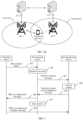
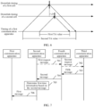
- the method includes: The first communication apparatus receives a first message from a second communication apparatus, where the first message includes first time information, the first time information is determined based on a first transmission delay and a second transmission delay, the first transmission delay is a transmission delay from the first communication apparatus to the second communication apparatus, the second transmission delay is a transmission delay from the first communication apparatus to a third communication apparatus, the second communication apparatus is a communication apparatus corresponding to a first cell, and the third communication apparatus is a communication apparatus corresponding to a second cell; the first communication apparatus determines a first timing advance TA value of the second cell based on the first time information; and the first communication apparatus sends uplink data to the third communication apparatus based on the first TA value.
- the first cell may be a source cell on which the first communication apparatus camps, and the second cell may be a target cell to which the first communication apparatus is to switch.
- the first TA value indicates an occasion at which the first communication apparatus sends the uplink data to the third communication apparatus.
- the second communication apparatus may determine the first time information based on the first transmission delay and the second transmission delay, and indicate the first TA value of the second cell by including the first time information in the first message.
- the first communication apparatus may determine the first TA value based on the first time information, and does not need to determine the TA value of the second cell in a random access process, to avoid service interruption caused by obtaining the TA value of the second cell in the random access process, and reduce interruption duration of the first communication apparatus in a process of in which the first communication apparatus switches from the second communication apparatus to the third communication apparatus.
- the first time information indicates the first TA value
- the first TA value is determined based on a second TA value and a first time difference
- the second TA value is a TA value of the first cell or a TA value of a first timing advance group (timing advance group, TAG) of the first communication apparatus
- the first time difference is a difference between the first transmission delay and the second transmission delay.
- the second TA value is a TA value used when the first communication apparatus performs uplink data transmission with the second communication apparatus. That the first time information indicates the first TA value may be specifically that the first time information includes the first TA value or includes information used to determine the first TA value, for example, the first time difference.
- the first TA value may be obtained by the second communication apparatus through calculation based on the second TA value and the first time difference and then sent to the first communication apparatus via the first message, and the first communication apparatus may directly obtain the first TA value from the first time information.
- the second TA value is a TA value used when the first communication apparatus performs uplink data transmission with the second communication apparatus.
- the first communication apparatus may obtain the first TA value through calculation based on the first time information and the second TA value, so that accuracy of the obtained first TA value is higher.
- the first time difference may alternatively be understood as a difference between time at which a first reference signal sent by the first communication apparatus is transmitted to the second communication apparatus and time at which the first reference signal is transmitted to the third communication apparatus
- the first TA value may be understood as a round-trip transmission delay from the first communication apparatus to the third communication apparatus.
- the first TA value is determined based on the second TA value and the difference between the first transmission delay and the second transmission delay, so that accuracy of the obtained first TA value may be higher.
- the first time information further includes a first downlink timing offset
- the first downlink timing offset is a downlink timing offset between the first cell and the second cell
- the first communication apparatus determining the first TA value based on the first time difference and the second TA value includes: The first communication apparatus determines the first TA value based on the first time difference, the second TA value, and the first downlink timing offset.
- the first downlink timing offset may be understood as a difference between subframe boundaries that are closest in time domain and that are of the first cell and the second cell.
- the first TA value is further related to the first downlink timing offset.
- the first communication apparatus obtains the first TA value through calculation based on the first time difference, the first downlink timing offset, and the second TA value, so that accuracy of the obtained first TA value may be higher.
- the method further includes: The first communication apparatus determines downlink frame timing of the second cell based on the first time difference and the first downlink frame timing, where the first downlink frame timing is downlink frame timing of the first cell or downlink frame timing of the first TAG.
- the downlink frame timing of the second cell indicates an occasion at which the first communication apparatus receives downlink data sent by the third communication apparatus
- the first downlink frame timing indicates an occasion at which the first communication apparatus receives downlink data sent by the second communication apparatus.
- the first communication apparatus may determine the downlink frame timing of the second cell based on the first time difference and the first downlink frame timing, so that the first communication apparatus can perform downlink data transmission with the third communication apparatus based on the downlink frame timing of the second cell, to implement downlink timing synchronization between the first communication apparatus and the third communication apparatus.
- the downlink frame timing of the second cell is obtained by adjusting the first downlink frame timing forward or backward by the first time difference.
- the first time information includes a second time difference
- the second time difference is a difference between a round-trip transmission delay from the first communication apparatus to the second communication apparatus and a round-trip transmission delay from the first communication apparatus to the third communication apparatus
- the first communication apparatus determining the first TA value based on the first time information and the second TA value includes: The first communication apparatus determines the first TA value based on the second time difference and the second TA value.
- the first TA value may be understood as the round-trip transmission delay from the first communication apparatus to the third communication apparatus
- the second TA value may be understood as the round-trip transmission delay from the first communication apparatus to the second communication apparatus.
- the first communication apparatus obtains the first TA value through calculation based on the second time difference and the second TA value, so that accuracy of the obtained first TA value may be higher.
- the second time difference is determined based on a first time difference and a first downlink timing offset
- the first time difference is a difference between the first transmission delay and the second transmission delay
- the first downlink timing offset is a downlink timing offset between the first cell and the second cell.
- the second time difference is related to the first downlink timing offset.
- the second communication apparatus may obtain the second time difference through calculation based on the first time difference and the first downlink timing offset, so that accuracy of the obtained second time difference is higher.
- the first time information indicates a TA value of the second cell.
- the second communication apparatus may determine the first time information based on the first transmission delay and the second transmission delay, and send the first time information to the first communication apparatus via the first message, so that the first communication apparatus can determine the first TA value based on the first time information, to avoid service interruption caused by obtaining the first TA value by the first communication apparatus in a random access process.
- the first time information indicates a first TA value
- the first TA value is determined based on a second TA value and a first time difference
- the first TA value is a TA value of the second cell
- the second TA value is a TA value of the first cell or a TA value of a first timing advance group TAG of the first communication apparatus
- the first time difference is a difference between the first transmission delay and the second transmission delay.
- the second TA value is a TA value used when the first communication apparatus performs uplink data transmission with the second communication apparatus. That the first time information indicates the first TA value may be specifically that the first time information includes the first TA value or includes information used to determine the first TA value, for example, the first time difference.
- the first TA value may be obtained by the second communication apparatus through calculation based on the second TA value and the first time difference and then sent to the first communication apparatus via the first message, and the first communication apparatus may directly obtain the first TA value from the first time information.
- the first communication apparatus may obtain the first TA value through calculation based on the second TA value and the first time difference.
- the first TA value is obtained through calculation based on the second TA value and the first time difference, so that the obtained first TA value can more accurately indicate the occasion at which the first communication apparatus sends the uplink data.
- the first time information includes a first time difference
- the first time difference is a difference between the first transmission delay and the second transmission delay.
- the second communication apparatus may send the first time difference to the first communication apparatus via the first time information, so that the first communication apparatus can determine the first TA value based on the first time difference.
- the first time information further includes a first downlink timing offset
- the first downlink timing offset is a downlink timing offset between the first cell and the second cell.
- the CU may determine, based on the first downlink timing and the second downlink timing, a difference between two closest subframe boundaries of the first cell and the second cell in time domain, to obtain the first downlink timing offset.
- the first time value indicates the time corresponding to the first subframe
- the second time value indicates the time corresponding to the second subframe. If subframes corresponding to the two closest subframe boundaries of the first cell and the second cell in time domain are the first subframe and the second subframe, the CU may calculate a difference between the first time value and the second time value, to obtain the first downlink timing offset.
- the first DU determines first time information based on the first downlink timing offset.
- the first time information indicates a first TA value
- the first time information may include the first TA value, a first time difference, the first downlink timing offset, or a second time difference.
- the first time information includes the second time difference
- the first DU determines the second time difference based on the first downlink timing offset and the first time difference.
- the first DU may obtain the second time difference through calculation based on Formula (6).
- the CU may further determine a first value, where the first value indicates a difference between the radio frame numbers corresponding to the two subframe boundaries and/or a difference between the subframe numbers corresponding to the two subframe boundaries.
- the CU may send the first value to the first DU via the second message, and the first DU sends the first value to the terminal device via the first message.
- the CU may include the first value in the L3 handover command, and send the first value to the terminal device via the L3 handover command.
- step 801 may be performed before step 802 to step 806, or may be performed after step 802 to step 806. This is not limited in this application.
- the first request message and the fourth message may be a same message, that is, the message includes the second downlink timing, and is used to request the first downlink timing offset.
- the first downlink timing offset may be obtained through interaction between the first DU and the CU and interaction between the CU and the second DU, and the first time information may be determined based on the first downlink timing offset, so that the terminal device can determine the first TA value based on the first time information, to avoid service interruption caused by obtaining the first TA value in a random access process.
- the terminal device can perform RACH-less HO, to reduce interruption duration in a process in which the terminal device switches from the first DU to the second DU.
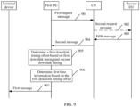
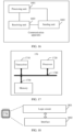
- FIG. 9 is an interaction flowchart of still another communication method according to an embodiment of this application.
- the method shown in FIG. 9 may be applied to the communication system shown in FIG. 2A .
- the method may be applied to a terminal device, a first DU, a CU, and a second DU.
- the first DU and the second DU are deployed under the CU.
- the terminal device may be the first communication apparatus shown above
- the first DU may be the second communication apparatus shown above
- the CU may be the fourth communication apparatus shown above
- the second DU may be the third communication apparatus shown above.
- the method includes but is not limited to the following steps.
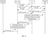
- the first DU sends a first request message, and correspondingly, the CU receives the first request message, where the first request message is used to request a first downlink timing offset.
- the method shown in FIG. 9 includes step 902.
- the CU sends a second request message, and correspondingly, the second DU receives the second request message, where the second request message is used to request first downlink timing, the first downlink timing is downlink timing of a second cell, and the second DU is a DU corresponding to the second cell.
- the CU sends a second message, and correspondingly, the first DU receives the second message, where the second message includes the first downlink timing.
- the CU may send the second message after receiving the fifth message, or send the second message after receiving the first request message.
- the second DU may periodically report the first downlink timing to the CU.
- the first DU determines a first downlink timing offset based on the first downlink timing and second downlink timing.
- the first DU determines first time information based on the first downlink timing offset.
- step 906 refers to the specific implementation of step 808 shown in FIG. 8 . Details are not described herein again.
- FIG. 10 is an interaction flowchart of still another communication method according to an embodiment of this application.
- the method shown in FIG. 10 may be applied to the communication system shown in FIG. 2A .
- the method may be applied to a terminal device, a first DU, a CU, and a second DU.
- the first DU and the second DU are deployed under the CU.
- the terminal device may be the first communication apparatus shown above
- the first DU may be the second communication apparatus shown above
- the CU may be the fourth communication apparatus shown above
- the second DU may be the third communication apparatus shown above.
- the method includes but is not limited to the following steps.
- the first DU sends a first request message, and correspondingly, the CU receives the first request message, where the first request message is used to request a first time difference.
- the first time difference is a difference between a transmission delay from the terminal device to the first DU and a transmission delay from the terminal device to the second DU.
- the method shown in FIG. 10 includes step 1002.
- the CU sends a fourth request message, and correspondingly, the first DU receives the fourth request message, where the fourth request message is used to request reference signal configuration information, and the reference signal configuration information is configuration information of a first reference signal sent by the terminal device.
- the first reference signal may be a sounding reference signal (sounding reference signal, SRS).
- the reference information configuration information may include a time-frequency resource corresponding to the first reference signal.
- the first DU sends a sixth message, and correspondingly, the CU receives the sixth message, where the sixth message includes the reference signal configuration information.
- the CU sends a seventh message, and correspondingly, the second DU receives the seventh message, where the seventh message includes the reference signal configuration information.
- the second DU determines, based on the reference signal configuration information, the time-frequency resource corresponding to the first reference signal sent by the terminal device.
- the method shown in FIG. 10 may include step 1005 and step 1006.
- the CU sends a fifth request message, and correspondingly, the first DU receives the fifth request message, where the fifth request message is used to request second receiving time.
- the CU sends a second request message, and correspondingly, the second DU receives the second request message, where the second request message is used to request first receiving time.
- the terminal device sends the first reference signal, and correspondingly, the first DU and the second DU receive the first reference signal.
- the first reference signal may be the SRS.
- the terminal device may send the first reference signal on the time-frequency resource corresponding to the first reference signal.
- the first DU and the second DU separately receive the first reference signal on the time-frequency resource, and record time at which the first reference signal is received, to obtain the first receiving time and the second receiving time.
- the first DU sends a third message, and correspondingly, the CU receives the third message, where the third message includes the second receiving time.
- the second DU sends a fifth message, and correspondingly, the CU receives the fifth message, where the fifth message includes the first receiving time.
- the CU determines the first time difference based on the first receiving time and the second receiving time.
- the CU calculates a difference between the first receiving time and the second receiving time, to obtain the first time difference.
- the CU sends a second message, and correspondingly, the first DU receives the second message, where the second message includes the first time difference.
- the first DU determines first time information based on the first time difference.
- the first DU sends a first message, and correspondingly, the terminal device receives the first message, where the first message includes the first time information.
- the CU may directly include the first time difference in an L3 handover command, and send the first time difference to the terminal device via the L3 handover command.
- step 1001 and step 1011 to step 1013 may not need to be performed.
- the first DU and the second DU exchange the reference signal configuration information and the receiving time of the first reference signal through the CU, so that the first DU can obtain the first time difference, and determine the first time information based on the first time difference, and the terminal device can determine a first TA value based on the first time information, to avoid service interruption caused by obtaining the first TA value in a random access process, and reduce interruption duration in a process in which the terminal device switches from the first DU to the second DU.
- FIG. 11 is an interaction flowchart of still another communication method according to an embodiment of this application.
- the method shown in FIG. 11 may be applied to the communication system shown in FIG. 2B .
- the method may be applied to a terminal device, a first DU, a CU, and a second DU.
- the first DU and the second DU are deployed under the CU.
- the terminal device may be the first communication apparatus shown above
- the first DU may be the second communication apparatus shown above
- the CU may be the fourth communication apparatus shown above
- the second DU may be the third communication apparatus shown above.
- the method includes but is not limited to the following steps.
- the first DU sends a first request message, and correspondingly, the CU receives the first request message, where the first request message is used to request a first time difference.
- the method shown in FIG. 11 includes step 1102.
- the CU sends a fourth request message, and correspondingly, the first DU receives the fourth request message, where the fourth request message is used to request reference signal configuration information.
- the first DU sends a sixth message, and correspondingly, the CU receives the sixth message, where the sixth message includes the reference signal configuration information.
- the CU sends a seventh message, and correspondingly, the second DU receives the seventh message, where the seventh message includes the reference signal configuration information.
- the method shown in FIG. 11 may include step 1105. 1105: The CU sends a second request message, and correspondingly, the second DU receives the second request message, where the second request message is used to request first receiving time.
- the terminal device sends a first reference signal, and correspondingly, the first DU and the second DU receive the first reference signal.
- the second DU sends a fifth message, and correspondingly, the CU receives the fifth message, where the fifth message includes the first receiving time.
- the CU sends a second message, and correspondingly, the first DU receives the second message, where the second message includes the first receiving time.
- the first DU determines the first time difference based on the first receiving time and second receiving time.
- the first DU calculates a difference between the first receiving time and the second receiving time, to obtain the first time difference.
- the first DU determines first time information based on the first time difference.
- the first DU sends a first message, and correspondingly, the terminal device receives the first message, where the first message includes the first time information.
- the first DU and the second DU exchange the reference signal configuration information and receiving time of the first reference signal through the CU, so that the first DU can determine the first time difference, and determine the first time information based on the first time difference, and the terminal device can determine a first TA value based on the first time information, to avoid service interruption caused by obtaining the first TA value in a random access process, and reduce interruption duration in a process in which the terminal device switches from the first DU to the second DU.
- FIG. 12 is an interaction flowchart of still another communication method according to an embodiment of this application.
- the method shown in FIG. 12 may be applied to the communication system shown in FIG. 2B .
- the method may be applied to a terminal device, a first network device, and a second network device.
- the first network device includes a first DU and a first CU
- the second network device includes a second CU and a second DU.
- the terminal device may be the first communication apparatus shown above
- the first DU may be the second communication apparatus shown above
- the first CU may be the fourth communication apparatus shown above
- the second CU may be the third communication apparatus shown above.
- the method includes but is not limited to the following steps.
- the first DU sends a first request message, and correspondingly, the first CU receives the first request message, where the first request message is used to request a first downlink timing offset.
- the first CU sends a second request message, and correspondingly, the second CU receives the second request message, where the second request message is used to request first downlink timing, and the first downlink timing is downlink timing of a second cell.
- the method shown in FIG. 12 includes step 1203 and step 1204.
- the second CU sends a sixth request message, and correspondingly, the second DU receives the sixth request message, where the sixth request message is used to request the first downlink timing.
- the first CU sends a third request message, and correspondingly, the first DU receives the third request message, where the third request message is used to request second downlink timing.
- the first DU sends a fourth message, and correspondingly, the first CU receives the fourth message, where the fourth message includes the second downlink timing.
- the second DU sends an eighth message, and correspondingly, the second CU receives the eighth message, where the eighth message includes the first downlink timing.
- the first CU sends a second message, and correspondingly, the first DU receives the second message, where the second message includes the first downlink timing offset.
- the first DU determines first time information based on the first downlink timing offset.
- the first DU sends a first message, and correspondingly, the terminal device receives the first message, where the first message includes the first time information.
- the first message may further include the first value.
- the first CU may directly include the first downlink timing offset in an L3 handover command, and send the first downlink timing offset to the terminal device via the L3 handover command.
- step 1201 and step 1209 to step 1211 may not be performed.
- step 1203, step 1204, step 1205, and step 1206 may not be performed.
- the method in FIG. 12 may include step 1202, step 1207, and step 1208.
- the first network device may send the first downlink timing offset to the terminal device via the L3 handover command.
- the L3 handover command may further include the first value.
- the first downlink timing offset may be obtained through interaction among the first DU, the first CU, the second CU, and the second DU, and the first time information is determined based on the first downlink timing offset, so that the first time information can indicate a first TA value, and the terminal device can determine the first TA value based on the first time information, to avoid service interruption caused by obtaining the first TA value in a random access process, and reduce interruption duration in a process in which the terminal device switches from the first DU to the second DU.
- FIG. 13 is an interaction flowchart of still another communication method according to an embodiment of this application.
- the method shown in FIG. 13 may be applied to the communication system shown in FIG. 2B .
- the method may be applied to a terminal device, a first network device, and a second network device.
- the first network device includes a first DU and a first CU
- the second network device includes a second CU and a second DU.
- the terminal device may be the first communication apparatus shown above
- the first DU may be the second communication apparatus shown above
- the first CU may be the fourth communication apparatus shown above
- the second CU may be the third communication apparatus shown above.
- the method includes but is not limited to the following steps.
- the first DU sends a first request message, and correspondingly, the first CU receives the first request message, where the first request message is used to request a first downlink timing offset.
- the method shown in FIG. 13 includes step 1303.
- the second CU sends a sixth request message, and correspondingly, the second DU receives the sixth request message, where the sixth request message is used to request the first downlink timing.
- the second DU sends an eighth message, and correspondingly, the second CU receives the eighth message, where the eighth message includes the first downlink timing.
- the second CU sends a fifth message, and correspondingly, the first CU receives the fifth message, where the fifth message includes the first downlink timing.
- the first CU sends a second message, and correspondingly, the first DU receives the second message, where the second message includes the first downlink timing.
- the first DU determines the first downlink timing offset based on the first downlink timing and second downlink timing.
- the first DU determines first time information based on the first downlink timing offset.
- the first DU sends a first message, and correspondingly, the terminal device receives the first message, where the first message includes the first time information.
- step 1301 and step 1302 may be performed before step 1303 and step 1304, or may be performed after step 1303 and step 1304. This is not limited in this application.
- the first DU may obtain downlink timing of a second cell through interaction among the first CU, the second CU, and the second DU, determine the first downlink timing offset based on downlink timing of a first cell and the downlink timing of the second cell, and determine the first time information based on the first downlink timing offset, so that the first time information can indicate a first TA value, and the terminal device can determine the first TA value based on the first time information, to avoid service interruption caused by obtaining the first TA value in a random access process, and reduce interruption duration in a process in which the terminal device switches from the first DU to the second DU.
- FIG. 14 is an interaction flowchart of still another communication method according to an embodiment of this application.
- the method shown in FIG. 14 may be applied to the communication system shown in FIG. 2B .
- the method may be applied to a terminal device, a first network device, and a second network device.
- the first network device includes a first DU and a first CU
- the second network device includes a second CU and a second DU.
- the terminal device may be the first communication apparatus shown above
- the first DU may be the second communication apparatus shown above
- the first CU may be the fourth communication apparatus shown above
- the second CU may be the third communication apparatus shown above.
- the method includes but is not limited to the following steps.
- the first DU sends a first request message, and correspondingly, the first CU receives the first request message, where the first request message is used to request a first time difference.
- the method shown in FIG. 14 includes step 1402.
- the first CU sends a fourth request message, and correspondingly, the first DU receives the fourth request message, where the fourth request message is used to request reference signal configuration information, and the reference signal configuration information is configuration information of a first reference signal sent by the terminal device.
- the first DU sends a sixth message, and correspondingly, the first CU receives the sixth message, where the sixth message includes the reference signal configuration information.
- the first CU sends a seventh message, and correspondingly, the second CU receives the seventh message, where the seventh message includes the reference signal configuration information.
- the second CU sends a ninth message, and correspondingly, the second DU receives the ninth message, where the ninth message includes the reference signal configuration information.
- the method shown in FIG. 14 may include step 1406, step 1407, and step 1408.
- the first CU sends a fifth request message, and correspondingly, the first DU receives the fifth request message, where the fifth request message is used to request second receiving time.
- the first CU sends a second request message, and correspondingly, the second CU receives the second request message, where the second request message is used to request first receiving time.
- the second CU sends a sixth request message, and correspondingly, the second DU receives the sixth request message, where the sixth request message is used to request the first receiving time.
- the terminal device sends the first reference signal, and correspondingly, the first DU and the second DU receive the first reference signal.
- the first DU sends a third message, and correspondingly, the first CU receives the third message, where the third message includes the second receiving time.
- the second DU sends an eighth message, and correspondingly, the second CU receives the eighth message, where the eighth message includes the first receiving time.
- the second CU sends a fifth message, and correspondingly, the first CU receives the fifth message, where the fifth message includes the first receiving time.
- the first CU determines the first time difference based on the first receiving time and the second receiving time.
- the first CU sends a second message, and correspondingly, the first DU receives the second message, where the second message includes the first time difference.
- the first DU determines first time information based on the first time difference.
- the first DU sends a first message, and correspondingly, the terminal device receives the first message, where the first message includes the first time information.
- the first CU may send the first time difference to the terminal device via an L3 handover command.
- step 1401 and step 1414 to step 1416 may not be performed in the method shown in FIG. 14 .
- step 1402, step 1403, step 1405, step 1406, step 1408, step 1410, and step 1411 may not be performed in the method shown in FIG. 14 .
- the first network device and the second network device when the first network device and the second network device are in the CU-DU integrated architecture, in the handover procedure triggered based on the L3 signaling, the first network device and the second network device separately perform the actions performed by the first CU and the second CU in step 1404, step 1412, and step 1413.
- the first network device may further send the first downlink timing offset to the terminal device via the L3 handover command.
- the first DU and the second DU exchange the reference signal configuration information and receiving time of the first reference signal through the first CU and the second CU, so that the first DU can obtain the first time difference, and determine the first time information based on the first time difference, and the terminal device can determine a first TA value based on the first time information, to avoid service interruption caused by obtaining the first TA value in a random access process, and reduce interruption duration in a process in which the terminal device switches from the first DU to the second DU.
- FIG. 15 is an interaction flowchart of still another communication method according to an embodiment of this application.
- the method shown in FIG. 15 may be applied to the communication system shown in FIG. 2B .
- the method may be applied to a terminal device, a first network device, and a second network device.
- the first network device includes a first DU and a first CU
- the second network device includes a second CU and a second DU.
- the terminal device may be the first communication apparatus shown above
- the first DU may be the second communication apparatus shown above
- the first CU may be the fourth communication apparatus shown above
- the second CU may be the third communication apparatus shown above.
- the method includes but is not limited to the following steps.
- the first DU sends a first request message, and correspondingly, the first CU receives the first request message, where the first request message is used to request a first time difference.
- the method shown in FIG. 15 includes step 1502.
- the first CU sends a fourth request message, and correspondingly, the first DU receives the fourth request message, where the fourth request message is used to request reference signal configuration information.
- the first DU sends a sixth message, and correspondingly, the first CU receives the sixth message, where the sixth message includes the reference signal configuration information.
- the first CU sends a seventh message, and correspondingly, the second CU receives the seventh message, where the seventh message includes the reference signal configuration information.
- the second CU sends a ninth message, and correspondingly, the second DU receives the ninth message, where the ninth message includes the reference signal configuration information.
- the method shown in FIG. 15 includes step 1506 and step 1507.
- the first CU sends a second request message, and correspondingly, the second CU receives the second request message, where the second request message is used to request first receiving time.
- the second CU sends a sixth request message, and correspondingly, the second DU receives the sixth request message, where the sixth request message is used to request the first receiving time.
- the terminal device sends a first reference signal, and correspondingly, the first DU and the second DU receive the first reference signal.
- the second DU sends an eighth message, and correspondingly, the second CU receives the eighth message, where the eighth message includes the first receiving time.
- the second CU sends a fifth message, and correspondingly, the first CU receives the fifth message, where the fifth message includes the first receiving time.
- the first CU sends a second message, and correspondingly, the first DU receives the second message, where the second message includes the first receiving time.
- the first DU determines the first time difference based on the first receiving time and second receiving time.
- the first DU determines first time information based on the first time difference.
- the first DU sends a first message, and correspondingly, the terminal device receives the first message, where the first message includes the first time information.
- the first DU and the second DU exchange the reference signal configuration information and receiving time of the first reference signal through the first CU and the second CU, so that the first DU can determine the first time difference, and determine the first time information based on the first time difference, and the terminal device can determine a first TA value based on the first time information, to avoid service interruption caused by obtaining the first TA value in a random access process, and reduce interruption duration in a process in which the terminal device switches from the first DU to the second DU.
- a communication apparatus provided in embodiments of this application is described below.
- the communication apparatus is divided into function modules based on the foregoing method embodiments.
- each function module may be divided to each corresponding function, or two or more functions may be integrated into one processing module.
- the integrated module may be implemented in a form of hardware, or may be implemented in a form of a software function module.
- module division is an example, and is merely a logical function division. In actual implementation, another division manner may be used. The following describes in detail communication apparatuses in embodiments of this application with reference to FIG. 16 to FIG. 18 .
- FIG. 16 is a diagram of a structure of a communication apparatus according to an embodiment of this application. As shown in FIG. 16 , the communication apparatus includes a processing unit 1601, a sending unit 1602, and a receiving unit 1603.
- the communication apparatus may be the first communication apparatus (or the terminal device) shown above.
- the communication apparatus shown in FIG. 16 may be configured to perform steps, functions, or the like performed by the first communication apparatus (or the terminal device) in the foregoing method embodiments.
- the communication apparatus may be a beamformed transmit device, a chip, or the like. This is not limited in this embodiment of this application.
- the receiving unit 1603 is configured to receive a first message.
- the processing unit 1601 is configured to determine a first TA value.
- the sending unit 1602 is configured to send uplink data.
- the processing unit 1601 is further configured to determine downlink frame timing of a second cell.
- first message the first TA value, first time information, and the like
- first message refers to the foregoing method embodiments, for example, the related descriptions of the methods shown in FIG. 5 , FIG. 7 , FIG. 8 , FIG. 9 , FIG. 10 , FIG. 11 , FIG. 12 , FIG. 13 , FIG. 14 , and FIG. 15 . Details are not described herein again.
- processing unit the sending unit, and the receiving unit shown in this embodiment of this application are merely examples.
- steps performed by the processing unit, the sending unit, and the receiving unit, or the like refer to the foregoing method embodiments. Details are not described herein again.
- FIG. 16 is reused.
- the communication apparatus may be the second communication apparatus (or the first DU) shown above.
- the communication apparatus shown in FIG. 16 may be configured to perform steps, functions, or the like performed by the second communication apparatus (or the second DU) in the foregoing method embodiments.
- the communication apparatus may be a beamformed receive device, a chip, or the like. This is not limited in this embodiment of this application.
- the processing unit 1601 is configured to determine first time information.
- the sending unit 1602 is configured to send a first message.
- the receiving unit 1603 is configured to receive a second message.
- the sending unit 1602 is further configured to send a fourth message.
- the receiving unit 1603 is further configured to receive a first reference signal.
- the sending unit 1602 is further configured to send a third message.
- the sending unit 1602 is further configured to send a first request message.
- FIG. 15 is reused.
- the communication apparatus may be the fourth communication apparatus (or the CU or the first CU) shown above.
- the communication apparatus shown in FIG. 15 may be configured to perform steps, functions, or the like performed by the fourth communication apparatus (or the CU or the first CU) in the foregoing method embodiments.
- the communication apparatus may be a beamformed receive device, a chip, or the like. This is not limited in this embodiment of this application.
- the receiving unit 1603 is configured to receive a fifth message.
- the sending unit 1602 is further configured to send a second message.
- the receiving unit 1603 is further configured to receive a third message; and the processing unit 1601 is configured to determine a first time difference.
- the receiving unit 1603 is further configured to receive a fourth message; and the processing unit 1601 is configured to determine a first downlink timing offset.
- the receiving unit 1603 is further configured to receive a first request message.
- the sending unit 1602 is further configured to send a second request message.
- the communication apparatus may be the third communication apparatus (or the second DU or the second CU) shown above.
- the communication apparatus shown in FIG. 16 may be configured to perform steps, functions, or the like performed by the third communication apparatus (or the second DU or the second CU) in the foregoing method embodiments.
- the communication apparatus may be a beamformed receive device, a chip, or the like. This is not limited in this embodiment of this application.
- the receiving unit 1603 is configured to receive a second request message.
- the sending unit 1602 is configured to send a fifth message.
- the receiving unit 1603 is further configured to receive a first reference signal.
- first communication apparatus the second communication apparatus, the third communication apparatus, and the fourth communication apparatus in embodiments of this application.
- the following describes possible product forms of the first communication apparatus, the second communication apparatus, the third communication apparatus, and the fourth communication apparatus. It should be understood that any form of product having a function of the first communication apparatus in FIG. 16 , any form of product having a function of the second communication apparatus in FIG. 16 , any form of product having a function of the third communication apparatus in FIG. 16 , or any form of product having a function of the fourth communication apparatus in FIG. 16 shall fall within the protection scope of embodiments of this application. It should be further understood that the following descriptions are merely an example, and does not limit product forms of the first communication apparatus, the second communication apparatus, the third communication apparatus, and the fourth communication apparatus in embodiments of this application.
- the processing unit 1601 may be one or more processors, the sending unit 1602 may be a transmitter, the receiving unit 1603 may be a receiver, and the sending unit and the receiving unit are integrated into one component, for example, a transceiver.
- the processing unit 1601 may be one or more processors (or the processing unit 1601 may be one or more logic circuits), the sending unit 1602 may be an output interface, the receiving unit 1603 may be an input interface, and the input interface and the output interface may be integrated into one unit, for example, an input/output interface. Details are described below.
- the processing unit 1601 may be one or more processors, and the sending unit 1602 and the receiving unit 1603 are integrated into one component, for example, a transceiver.
- the processor and the transceiver may be coupled, or the like.
- a connection manner between the processor and the transceiver is not limited in this embodiment of this application.
- the processor 1720 is configured to determine first time information; and the transceiver 1710 is configured to send a first message.
- the transceiver 1710 is further configured to receive a second message.
- the transceiver 1710 is further configured to send a fourth message.
- the transceiver 1710 is further configured to receive a first reference signal.
- the transceiver 1710 is further configured to send a third message.
- the transceiver 1710 is further configured to send a first request message.
- the transceiver 1710 when the communication apparatus is configured to perform the steps, the methods, or the functions performed by the fourth communication apparatus, the transceiver 1710 is configured to receive a fifth message and send a second message.
- the transceiver 1710 is further configured to receive a third message; and the processor 1720 is configured to determine a first time difference.
- the transceiver 1710 is further configured to receive a fourth message, and the processor 1720 is configured to determine a first downlink timing offset and the like.
- the transceiver 1710 is configured to receive a second request message and send a fifth message.
- the transceiver 1710 is further configured to receive a first reference signal.
- processors and the transceiver refer to the descriptions of the processing unit, the sending unit, and the receiving unit shown in FIG. 16 . Details are not described herein again.
- the transceiver may include a receiver and a transmitter, the receiver is configured to perform a receiving function (or operation), and the transmitter is configured to perform a transmitting function (or operation).
- the transceiver is configured to communicate with another device/apparatus through a transmission medium.
- the communication apparatus 170 may further include one or more memories 1730, configured to store program instructions and/or data.
- the memory 1730 is coupled to the processor 1720.
- the coupling in this embodiment of this application may be an indirect coupling or a communication connection between apparatuses, units, or modules in an electrical form, a mechanical form, or another form, and is used for information exchange between the apparatuses, the units, or the modules.
- the processor 1720 may cooperate with the memory 1730.
- the processor 1720 may execute the program instructions stored in the memory 1730.
- at least one of the one or more memories may be included in the processor.
- the processor may be a general-purpose processor, a digital signal processor, an application-specific integrated circuit, a field programmable gate array or another programmable logic device, a discrete gate or transistor logic device, a discrete hardware component, or the like.
- the processor can implement or execute the methods, the steps, and the logical block diagrams disclosed in embodiments of this application.
- the general-purpose processor may be a microprocessor or any conventional processor or the like.
- the steps of the methods disclosed in combination with embodiments of this application may be directly implemented by a hardware processor, or may be implemented by using a combination of hardware and software modules in the processor, or the like.
- the memory may include but is not limited to a nonvolatile memory such as a hard disk drive (hard disk drive, HDD) or a solid-state drive (solid-state drive, SSD), a random access memory (Random Access Memory, RAM), an erasable programmable read-only memory (Erasable Programmable ROM, EPROM), a read-only memory (Read-Only Memory, ROM), or a compact read-only memory (Compact Disc Read-Only Memory, CD-ROM).
- the memory is any storage medium that can be used to carry or store program code in a form of an instruction or a data structure and that can be read and/or written by a computer (for example, the communication apparatus shown in this application). However, this application is not limited thereto.
- the memory in embodiments of this application may alternatively be a circuit or any other apparatus that can implement a storage function, and is configured to store the program instructions and/or the data.
- the processor 1720 is mainly configured to: process a communication protocol and communication data, control an entire communication apparatus, execute a software program, and process data of the software program.
- the memory 1730 is mainly configured to store the software program and the data.
- the transceiver 1710 may include a control circuit and an antenna.
- the control circuit is mainly configured to perform a conversion between a baseband signal and a radio frequency signal, and process the radio frequency signal.
- the antenna is mainly configured to receive or send a radio frequency signal in a form of an electromagnetic wave.
- An input/output apparatus such as a touchscreen, a display, or a keyboard, is mainly configured to receive data input by a user and output data to the user.
- the processor 1720 may read the software program in the memory 1730, interpret and execute instructions of the software program, and process data of the software program.
- the processor 1720 performs baseband processing on the to-be-sent data, and outputs a baseband signal to a radio frequency circuit.
- the radio frequency circuit performs radio frequency processing on the baseband signal, and then sends out the radio frequency signal through the antenna in a form of an electromagnetic wave.
- the radio frequency circuit receives a radio frequency signal through the antenna, converts the radio frequency signal into a baseband signal, and outputs the baseband signal to the processor 1720.
- the processor 1720 converts the baseband signal into data, and processes the data.
- the radio frequency circuit and the antenna may be disposed independently of the processor that performs baseband processing.
- the radio frequency circuit and the antenna may be remotely disposed independently of the communication apparatus.
- the communication apparatus shown in this embodiment of this application may alternatively include more components than those shown in FIG. 17 , or the like. This is not limited in this embodiment of this application.
- the methods performed by the processor and the transceiver are merely examples. For specific steps performed by the processor and the transceiver, refer to the methods described above.
- the processing unit 1601 may be one or more logic circuits
- the sending unit 1602 may be an output interface
- the receiving unit 1603 may be an input interface
- the input interface and the output interface may be integrated into one unit, for example, an input/output interface.
- the input/output interface is also referred to as a communication interface, an interface circuit, an interface, or the like.
- a communication apparatus shown in FIG. 18 includes a logic circuit 1801 and an interface 1802.
- the processing unit 1601 may be implemented by using the logic circuit 1801
- the sending unit 1602 and the receiving unit 1603 may be implemented by using the interface 1802.
- the logic circuit 1801 may be a chip, a processing circuit, an integrated circuit, a system on chip (system on chip, SoC), or the like.
- the interface 1802 may be a communication interface, an input/output interface, a pin, or the like.
- FIG. 18 the foregoing communication apparatus is shown by using a chip as an example, and the chip includes the logic circuit 1801 and the interface 1802.
- the logic circuit and the interface may be coupled to each other.
- a specific manner of connection between the logic circuit and the interface is not limited in this embodiment of this application.
- the interface 1802 is configured to input a first message and output uplink data; and the logic circuit 1801 is configured to determine a first TA value.
- the processor 1720 is further configured to determine downlink frame timing of a second cell.
- the interface 1802 when the communication apparatus is configured to perform the steps, the methods, or the functions performed by the fourth communication apparatus, the interface 1802 is configured to input a fifth message and output a second message.
- the interface 1802 is further configured to input a third message; and the logic circuit 1801 is configured to determine a first time difference.
- the interface 1802 is further configured to input a fourth message, and the logic circuit 1801 is configured to determine a first downlink timing offset.
- the communication apparatus shown in embodiments of this application may implement the methods provided in embodiments of this application in a form of hardware, or may implement the methods provided in embodiments of this application in a form of software. This is not limited in embodiments of this application.
- An embodiment of this application further provides a communication system.
- the communication system includes at least one of the following: a first communication apparatus, a second communication apparatus, a third communication apparatus, and a fourth communication apparatus.
- the first communication apparatus, the second communication apparatus, the third communication apparatus, and the fourth communication apparatus may be configured to perform the method in any one of the foregoing embodiments (as shown in FIG. 5 , FIG. 7 , FIG. 8 , FIG. 9 , FIG. 10 , FIG. 11 , FIG. 12 , FIG. 13 , FIG. 14 , and FIG. 15 ).
- This application further provides a computer program.
- the computer program is used to implement operations and/or processing performed by the second communication apparatus in the methods provided in this application.
- This application further provides a computer program.
- the computer program is configured to implement operations and/or processing performed by the third communication apparatus in the method provided in this application.
- This application further provides a computer program.
- the computer program is configured to implement operations and/or processing performed by the fourth communication apparatus in the method provided in this application.
- This application further provides a computer-readable storage medium.
- the computer-readable storage medium stores computer code.
- the computer code When the computer code is run on a computer, the computer is enabled to perform operations and/or processing performed by the first communication apparatus in the methods provided in this application.
- This application further provides a computer-readable storage medium.
- the computer-readable storage medium stores computer code.
- the computer code When the computer code is run on a computer, the computer is enabled to perform operations and/or processing performed by the second communication apparatus in the methods provided in this application.
- This application further provides a computer-readable storage medium.
- the computer-readable storage medium stores computer code.
- the computer code When the computer code is run on a computer, the computer is enabled to perform operations and/or processing performed by the fourth communication apparatus in the methods provided in this application.
- the computer program product includes computer code or a computer program.
- the computer code or the computer program is run on a computer, operations and/or processing performed by the second communication apparatus in the methods provided in this application are/is performed.
- the disclosed system, apparatus, and method may be implemented in other manners.
- the described apparatus embodiment is merely an example.
- division into the units is merely logical function division and may be other division in actual implementation.
- a plurality of units or components may be combined or integrated into another system, or some features may be ignored or not performed.
- the displayed or discussed mutual couplings or direct couplings or communication connections may be implemented through some interfaces, indirect couplings or communication connections between the apparatuses or units, or electrical connections, mechanical connections, or connections in other forms.
Landscapes
- Engineering & Computer Science (AREA)
- Computer Networks & Wireless Communication (AREA)
- Signal Processing (AREA)
- Mobile Radio Communication Systems (AREA)
- Communication Control (AREA)
Applications Claiming Priority (2)
| Application Number | Priority Date | Filing Date | Title |
|---|---|---|---|
| CN202211163296.XA CN117835336A (zh) | 2022-09-23 | 2022-09-23 | 通信方法、通信装置及通信系统 |
| PCT/CN2023/117087 WO2024060992A1 (zh) | 2022-09-23 | 2023-09-05 | 通信方法、通信装置及通信系统 |
Publications (2)
| Publication Number | Publication Date |
|---|---|
| EP4580251A1 true EP4580251A1 (de) | 2025-07-02 |
| EP4580251A4 EP4580251A4 (de) | 2025-11-12 |
Family
ID=90453831
Family Applications (1)
| Application Number | Title | Priority Date | Filing Date |
|---|---|---|---|
| EP23867283.6A Pending EP4580251A4 (de) | 2022-09-23 | 2023-09-05 | Kommunikationsverfahren, kommunikationsvorrichtung und kommunikationssystem |
Country Status (6)
| Country | Link |
|---|---|
| US (1) | US20250254638A1 (de) |
| EP (1) | EP4580251A4 (de) |
| JP (1) | JP2025531426A (de) |
| CN (1) | CN117835336A (de) |
| TW (1) | TW202425700A (de) |
| WO (1) | WO2024060992A1 (de) |
Family Cites Families (9)
| Publication number | Priority date | Publication date | Assignee | Title |
|---|---|---|---|---|
| JP6125939B2 (ja) * | 2013-07-29 | 2017-05-10 | 京セラ株式会社 | ユーザ端末及びプロセッサ |
| WO2017130852A1 (ja) * | 2016-01-25 | 2017-08-03 | 京セラ株式会社 | 無線端末及び基地局 |
| CN110167131B (zh) * | 2018-02-14 | 2020-11-17 | 华为技术有限公司 | 一种中继传输的方法及装置 |
| US11082898B2 (en) * | 2019-02-20 | 2021-08-03 | Qualcomm Incorporated | Random access channel (RACH)-less timing advance determination |
| US11184872B2 (en) * | 2019-04-04 | 2021-11-23 | Qualcomm Incorporated | Reference timing delivery to user equipment with propagation delay compensation |
| US11503515B2 (en) * | 2019-05-01 | 2022-11-15 | Institute For Information Industry | User equipment and base station for mobile communication system |
| WO2021087864A1 (en) * | 2019-11-07 | 2021-05-14 | Apple Inc. | Uplink transmission for dual active protocol stack handover |
| CN114070376A (zh) * | 2020-07-30 | 2022-02-18 | 华为技术有限公司 | 确定终端设备定时提前量的方法和通信装置 |
| US20240049097A1 (en) * | 2021-01-08 | 2024-02-08 | Nokia Technologies Oy | Methods, apparatuses, and computer program products for fast cell selection using conditional handover and intercell beam management reporting |
-
2022
- 2022-09-23 CN CN202211163296.XA patent/CN117835336A/zh active Pending
-
2023
- 2023-09-05 EP EP23867283.6A patent/EP4580251A4/de active Pending
- 2023-09-05 WO PCT/CN2023/117087 patent/WO2024060992A1/zh not_active Ceased
- 2023-09-05 JP JP2025517516A patent/JP2025531426A/ja active Pending
- 2023-09-22 TW TW112136296A patent/TW202425700A/zh unknown
-
2025
- 2025-03-21 US US19/086,569 patent/US20250254638A1/en active Pending
Also Published As
| Publication number | Publication date |
|---|---|
| US20250254638A1 (en) | 2025-08-07 |
| JP2025531426A (ja) | 2025-09-19 |
| WO2024060992A1 (zh) | 2024-03-28 |
| CN117835336A (zh) | 2024-04-05 |
| TW202425700A (zh) | 2024-06-16 |
| EP4580251A4 (de) | 2025-11-12 |
Similar Documents
| Publication | Publication Date | Title |
|---|---|---|
| AU2019319462B2 (en) | Method and apparatus for wireless communication | |
| US20230112574A1 (en) | Timing advance acquisition for neighbor cells | |
| CA2827218C (en) | Time-advanced random access channel transmission | |
| US20230102742A1 (en) | Timing advance acquisition for multiple cells | |
| EP3165042B1 (de) | Verfahren zur unterstützung einer drahtlosen vorrichtung bei der durchführung von uplink-übertragungen | |
| US10334542B2 (en) | Wireless device, a first access node and methods therein | |
| CN112806063A (zh) | 用于小区切换的方法及设备 | |
| TWI432047B (zh) | 無線電存取網路之方法、網路節點及在無線電存取網路中運算之方法 | |
| US20250133513A1 (en) | Wireless communication method, terminal device, and network device | |
| EP3925395A1 (de) | Steuerungsmechanismus zur unterstützung des verbindungsaufbauvorgangs | |
| CN104521252A (zh) | 一种umts到lte的网络切换方法、设备及系统 | |
| US20250184936A1 (en) | Communication method and related apparatus | |
| US20250227584A1 (en) | Method and apparatus for information reception and information transmission | |
| EP4580251A1 (de) | Kommunikationsverfahren, kommunikationsvorrichtung und kommunikationssystem | |
| CN115915400A (zh) | 一种随机接入方法及装置 | |
| EP3562206A1 (de) | Informationsübertragungsverfahren, netzwerkvorrichtung und endgerätevorrichtung | |
| EP4521779A1 (de) | Positionierungsverfahren und kommunikationsvorrichtung | |
| WO2025036659A1 (en) | Method and apparatus for enhancements in measurements/reporting | |
| US20250374217A1 (en) | Information transfer method and apparatus | |
| US20260032614A1 (en) | Communication method and communication apparatus | |
| EP4668852A1 (de) | Direktzugriffsverfahren und -vorrichtung | |
| CN114501558B (zh) | 一种信息传输、获取方法及装置 | |
| EP4697805A1 (de) | Übergabeverfahren und -vorrichtung | |
| WO2025036661A1 (en) | Enhancements for l1 measurements/reporting and beam switching for target cells with carrier aggregation | |
| CN121013137A (zh) | 通信方法及装置 |
Legal Events
| Date | Code | Title | Description |
|---|---|---|---|
| STAA | Information on the status of an ep patent application or granted ep patent |
Free format text: STATUS: THE INTERNATIONAL PUBLICATION HAS BEEN MADE |
|
| PUAI | Public reference made under article 153(3) epc to a published international application that has entered the european phase |
Free format text: ORIGINAL CODE: 0009012 |
|
| STAA | Information on the status of an ep patent application or granted ep patent |
Free format text: STATUS: REQUEST FOR EXAMINATION WAS MADE |
|
| 17P | Request for examination filed |
Effective date: 20250325 |
|
| AK | Designated contracting states |
Kind code of ref document: A1 Designated state(s): AL AT BE BG CH CY CZ DE DK EE ES FI FR GB GR HR HU IE IS IT LI LT LU LV MC ME MK MT NL NO PL PT RO RS SE SI SK SM TR |
|
| A4 | Supplementary search report drawn up and despatched |
Effective date: 20251015 |
|
| RIC1 | Information provided on ipc code assigned before grant |
Ipc: H04W 36/00 20090101AFI20251009BHEP Ipc: H04W 56/00 20090101ALI20251009BHEP |
|
| DAV | Request for validation of the european patent (deleted) | ||
| DAX | Request for extension of the european patent (deleted) |