EP4521779A1 - Positionierungsverfahren und kommunikationsvorrichtung - Google Patents
Positionierungsverfahren und kommunikationsvorrichtung Download PDFInfo
- Publication number
- EP4521779A1 EP4521779A1 EP23806876.1A EP23806876A EP4521779A1 EP 4521779 A1 EP4521779 A1 EP 4521779A1 EP 23806876 A EP23806876 A EP 23806876A EP 4521779 A1 EP4521779 A1 EP 4521779A1
- Authority
- EP
- European Patent Office
- Prior art keywords
- terminal device
- information
- network device
- reference signal
- request
- Prior art date
- Legal status (The legal status is an assumption and is not a legal conclusion. Google has not performed a legal analysis and makes no representation as to the accuracy of the status listed.)
- Pending
Links
Images


Classifications
-
- H—ELECTRICITY
- H04—ELECTRIC COMMUNICATION TECHNIQUE
- H04W—WIRELESS COMMUNICATION NETWORKS
- H04W64/00—Locating users or terminals or network equipment for network management purposes, e.g. mobility management
-
- G—PHYSICS
- G01—MEASURING; TESTING
- G01S—RADIO DIRECTION-FINDING; RADIO NAVIGATION; DETERMINING DISTANCE OR VELOCITY BY USE OF RADIO WAVES; LOCATING OR PRESENCE-DETECTING BY USE OF THE REFLECTION OR RERADIATION OF RADIO WAVES; ANALOGOUS ARRANGEMENTS USING OTHER WAVES
- G01S5/00—Position-fixing by co-ordinating two or more direction or position line determinations; Position-fixing by co-ordinating two or more distance determinations
- G01S5/0009—Transmission of position information to remote stations
- G01S5/0045—Transmission from base station to mobile station
- G01S5/0063—Transmission from base station to mobile station of measured values, i.e. measurement on base station and position calculation on mobile
-
- G—PHYSICS
- G01—MEASURING; TESTING
- G01S—RADIO DIRECTION-FINDING; RADIO NAVIGATION; DETERMINING DISTANCE OR VELOCITY BY USE OF RADIO WAVES; LOCATING OR PRESENCE-DETECTING BY USE OF THE REFLECTION OR RERADIATION OF RADIO WAVES; ANALOGOUS ARRANGEMENTS USING OTHER WAVES
- G01S5/00—Position-fixing by co-ordinating two or more direction or position line determinations; Position-fixing by co-ordinating two or more distance determinations
- G01S5/0009—Transmission of position information to remote stations
- G01S5/0072—Transmission between mobile stations, e.g. anti-collision systems
-
- G—PHYSICS
- G01—MEASURING; TESTING
- G01S—RADIO DIRECTION-FINDING; RADIO NAVIGATION; DETERMINING DISTANCE OR VELOCITY BY USE OF RADIO WAVES; LOCATING OR PRESENCE-DETECTING BY USE OF THE REFLECTION OR RERADIATION OF RADIO WAVES; ANALOGOUS ARRANGEMENTS USING OTHER WAVES
- G01S5/00—Position-fixing by co-ordinating two or more direction or position line determinations; Position-fixing by co-ordinating two or more distance determinations
- G01S5/02—Position-fixing by co-ordinating two or more direction or position line determinations; Position-fixing by co-ordinating two or more distance determinations using radio waves
- G01S5/0205—Details
- G01S5/0236—Assistance data, e.g. base station almanac
-
- H—ELECTRICITY
- H04—ELECTRIC COMMUNICATION TECHNIQUE
- H04W—WIRELESS COMMUNICATION NETWORKS
- H04W56/00—Synchronisation arrangements
-
- H—ELECTRICITY
- H04—ELECTRIC COMMUNICATION TECHNIQUE
- H04W—WIRELESS COMMUNICATION NETWORKS
- H04W56/00—Synchronisation arrangements
- H04W56/001—Synchronization between nodes
- H04W56/0015—Synchronization between nodes one node acting as a reference for the others
-
- H—ELECTRICITY
- H04—ELECTRIC COMMUNICATION TECHNIQUE
- H04W—WIRELESS COMMUNICATION NETWORKS
- H04W72/00—Local resource management
- H04W72/20—Control channels or signalling for resource management
- H04W72/25—Control channels or signalling for resource management between terminals via a wireless link, e.g. sidelink
-
- H—ELECTRICITY
- H04—ELECTRIC COMMUNICATION TECHNIQUE
- H04W—WIRELESS COMMUNICATION NETWORKS
- H04W4/00—Services specially adapted for wireless communication networks; Facilities therefor
- H04W4/02—Services making use of location information
-
- H—ELECTRICITY
- H04—ELECTRIC COMMUNICATION TECHNIQUE
- H04W—WIRELESS COMMUNICATION NETWORKS
- H04W92/00—Interfaces specially adapted for wireless communication networks
- H04W92/16—Interfaces between hierarchically similar devices
- H04W92/18—Interfaces between hierarchically similar devices between terminal devices
Definitions
- This application relates to the field of wireless communication, and more specifically, to a positioning method and a communication apparatus.
- a current positioning method is mainly used to position a target terminal device based on a reference signal of a Uu interface in a positioning scenario.
- a sidelink is used in the positioning scenario, to be specific, at least one network element, terminal, or entity (for example, a road side unit (road side unit, RSU)) that can send a reference signal of a PC5 interface is used in the positioning scenario, the target terminal device needs to be positioned based on the reference signal of the Uu interface and the reference signal of the PC5 interface in the positioning scenario, or the target terminal device needs to be positioned based only on the reference signal of the PC5 interface in the positioning scenario.
- sending and receiving of the sidelink reference signal of the PC5 interface are different from sending and receiving of the reference signal of the Uu interface, location information of the target terminal device cannot be accurately calculated.
- Embodiments of this application provide a positioning method and a communication apparatus.
- a location of a target terminal device may be accurately calculated in a positioning scenario including sidelink communication.
- a positioning method is provided.
- the method may be performed by a first terminal device, or may be performed by a component (for example, a chip or a circuit) of the first terminal device. This is not limited.
- a component for example, a chip or a circuit
- the method may include: The first terminal device obtains first information.
- the first information includes synchronization information of a second terminal device.
- the synchronization information of the second terminal device includes synchronization information between the second terminal device and a synchronization source of the second terminal device.
- the second terminal device is configured to assist in positioning a location of the first terminal device.
- the second terminal device communicates with the first terminal device through a sidelink.
- the first terminal device determines location information of the first terminal device based on the first information.
- the first terminal device when the second terminal device that assists in positioning the location of the first terminal device communicates with the first terminal device through the sidelink in a positioning scenario, to be specific, when the first terminal device needs to be positioned based on a sidelink reference signal of a PC5 interface in the positioning scenario, the first terminal device can accurately calculate the location information of the first terminal device based on the obtained synchronization information of the second terminal device.
- the first terminal device obtains first information includes: The first terminal device receives the first information from a second network device.
- the second network device in this application is a device having a location management function.
- the second network device may be a part of a core network, or may be integrated into a network device.
- the second network device may be a location management function LMF, or a location management component LMC in a serving network device of a to-be-positioned terminal device.
- the second network device may also be referred to as a location management device or a location center.
- a name of the location management device is not limited in this application. In a future evolved technology, the location management device may also be assigned another name.
- that the first terminal device obtains first information includes: The first terminal device receives a first configuration message from a second network device.
- the first configuration message includes configuration information of a sidelink reference signal of the second terminal device.
- the configuration information of the sidelink reference signal of the second terminal device is used by the first terminal device to receive the sidelink reference signal of the second terminal device.
- the first configuration message further includes the first information.
- the first terminal device obtains first information includes: The first terminal device receives the first information from the second terminal device.
- the method further includes: The first terminal device receives a second configuration message from the second terminal device.
- the second configuration message includes configuration information of a sidelink reference signal of the second terminal device.
- the configuration information of the sidelink reference signal of the second terminal device is used by the first terminal device to receive the sidelink reference signal of the second terminal device.
- the second configuration message further includes the first information.
- the method further includes: The first terminal device sends a first message to the second network device.
- the first message includes an identifier of the second terminal device.
- the first terminal device may report, to the second network device, the identifier of the second terminal device that can be configured to position the location of the first terminal device, to avoid a resource waste caused when the second terminal device that does not need to send a sidelink reference signal also sends the sidelink reference signal to the first terminal device.
- the second terminal device is one or more terminal devices.
- a positioning method is provided.
- the method may be performed by a second network device, or may be performed by a component (for example, a chip or a circuit) of the second network device. This is not limited.
- a component for example, a chip or a circuit
- the method may include: The second network device obtains first information.
- the first information includes synchronization information of a second terminal device.
- the synchronization information of the second terminal device includes synchronization information between the second terminal device and a synchronization source of the second terminal device.
- the second terminal device is configured to assist in positioning a location of a first terminal device.
- the second terminal device communicates with the first terminal device through a sidelink.
- the second network device determines location information of the first terminal device based on the first information.
- the second network device can accurately calculate the location information of the first terminal device based on the obtained synchronization information of the second terminal device.
- that the second network device obtains first information includes: The second network device receives the first information from the second terminal device.
- that the second network device obtains first information includes: The second network device receives the first information from a serving base station network device of the second terminal device.
- that the second network device obtains first information includes: The second network device receives the first information from the first terminal device.
- the method further includes: The second network device sends a third request message to the first terminal device.
- the third request message is used to request the synchronization information of the second terminal device.
- the second network device receives a third request response message from the first terminal device.
- the third request response message includes the first information.
- the method further includes: The second network device sends a fourth request message to a serving base station network device of the second terminal device.
- the fourth request message is used to request to configure configuration information of a sidelink reference signal of the second terminal device.
- the configuration information of the sidelink reference signal of the second terminal device is used by the first terminal device to receive the sidelink reference signal of the second terminal device.
- the second network device receives a fourth request response message from the serving base station network device of the second terminal device.
- the fourth request response message includes the configuration information of the sidelink reference signal of the second terminal device.
- the fourth request response message includes the first information.
- the method further includes:
- the second terminal device is one or more terminal devices.
- the method may include: The second network device obtains first information.
- the first information includes synchronization information of the second terminal device.
- the synchronization information of the second terminal device includes synchronization information between the second terminal device and a synchronization source of the second terminal device.
- the second terminal device is configured to assist in positioning a location of a first terminal device.
- the second terminal device communicates with the first terminal device through a sidelink.
- the second network device sends the first information to the first terminal device.
- the method may include: The first network device obtains first information.
- the first information includes synchronization information of a second terminal device.
- the first network device is a serving network device of the second terminal device.
- the synchronization information of the second terminal device includes synchronization information between the second terminal device and a synchronization source of the second terminal device.
- the second terminal device is configured to assist in positioning a location of a first terminal device.
- the second terminal device communicates with the first terminal device through a sidelink.
- the first network device sends the first information to a second network device.
- a communication apparatus configured to perform the method according to the first aspect or the third aspect.
- the apparatus may include units and/or modules, for example, a processing unit and/or a communication unit, configured to perform the method according to any one of the first aspect, the third aspect, or the possible implementations of the first aspect or the third aspect.
- the apparatus is a chip, a chip system, or a circuit used in the second network device.
- the communication unit may be an input/output interface, an interface circuit, an output circuit, an input circuit, a pin, a related circuit, or the like on the chip, the chip system, or the circuit
- the processing unit may be at least one processor, processing circuit, logic circuit, or the like. It may be understood that when the apparatus is the chip, the chip system, or the circuit used in the second network device, the second network device in the method according to any one of the second aspect, the fourth aspect, or the possible implementations of the second aspect or the fourth aspect is the apparatus.
- the apparatus is a first network device.
- the communication unit may be a transceiver or an input/output interface
- the processing unit may be at least one processor.
- the transceiver may be a transceiver circuit.
- the input/output interface may be an input/output circuit.
- the apparatus is a second terminal device.
- the communication unit may be a transceiver or an input/output interface
- the processing unit may be at least one processor.
- the transceiver may be a transceiver circuit.
- the input/output interface may be an input/output circuit.
- this application provides a communication device, including at least one processor.
- the at least one processor is coupled to at least one memory.
- the at least one memory is configured to store a computer program or instructions.
- the at least one processor is configured to invoke the computer program or the instructions from the at least one memory and run the computer program or the instructions, to enable the communication device to perform the method according to any one of the first aspect, the third aspect, or the possible implementations of the first aspect or the third aspect.
- this application provides a communication device, including at least one processor.
- the at least one processor is coupled to at least one memory.
- the at least one memory is configured to store a computer program or instructions.
- the at least one processor is configured to invoke the computer program or the instructions from the at least one memory and run the computer program or the instructions, to enable the communication device to perform the method according to any one of the fifth aspect and the possible implementations of the fifth aspect.
- this application provides a communication device, including at least one processor.
- the at least one processor is coupled to at least one memory.
- the at least one memory is configured to store a computer program or instructions.
- the at least one processor is configured to invoke the computer program or the instructions from the at least one memory and run the computer program or the instructions, to enable the communication device to perform the method according to any one of the sixth aspect and the possible implementations of the sixth aspect.
- a computer-readable storage medium stores program code executed by a device.
- the program code is used to perform the method according to any one of the first aspect, the second aspect, the third aspect, the fourth aspect, the fifth aspect, the sixth aspect, and the possible implementations of the first aspect, the second aspect, the third aspect, the fourth aspect, the fifth aspect, or the sixth aspect.
- a computer program product including instructions is provided.
- the computer is enabled to perform the method according to any one of the first aspect, the second aspect, the third aspect, the fourth aspect, the fifth aspect, the sixth aspect, and the possible implementations of the first aspect, the second aspect, the third aspect, the fourth aspect, the fifth aspect, or the sixth aspect.
- a chip includes a processor and a communication interface.
- the processor reads, through the communication interface, instructions stored in a memory, to perform the method according to any one of the first aspect, the second aspect, the third aspect, the fourth aspect, the fifth aspect, the sixth aspect, and the possible implementations of the first aspect, the second aspect, the third aspect, the fourth aspect, the fifth aspect, or the sixth aspect.
- the chip further includes a memory.
- the memory stores a computer program or instructions.
- the processor is configured to execute the computer program or the instructions stored in the memory.
- the processor is configured to perform the method according to any one of the first aspect, the second aspect, the third aspect, the fourth aspect, the fifth aspect, the sixth aspect, and the possible implementations of the first aspect, the second aspect, the third aspect, the fourth aspect, the fifth aspect, or the sixth aspect.
- a communication system includes one or more communication devices shown in the eleventh aspect to the fourteenth aspect.
- the technical solutions of this application may be applied to a scenario in which a terminal device needs to be positioned.
- the technical solutions may be applied to a positioning scenario in which a time difference of arrival (time difference of arrival, TDOA), a downlink time difference of arrival (downlink time difference of arrival, DL-TDOA), an uplink time difference of arrival (uplink time difference of arrival, UL-TDOA), an enhanced cell identifier (enhanced cell identifier, E-CID), or a multi round trip time (multi round trip time, multi-RTT) technology is used.
- TDOA time difference of arrival
- DL-TDOA downlink time difference of arrival
- uplink time difference of arrival uplink time difference of arrival
- UL-TDOA uplink time difference of arrival
- E-CID enhanced cell identifier
- multi-RTT multi round trip time
- LTE long term evolution
- FDD frequency division duplex
- TDD time division duplex
- UMTS universal mobile telecommunications system
- WiMAX worldwide interoperability for microwave access
- 5G 5th generation
- 5G new radio
- NR new radio
- future communication system a vehicle-to-everything (vehicle-to-X V2X) system.
- vehicle-to-X V2X vehicle-to-everything
- the V2X may include vehicle-to-network (vehicle-to-network, V2N), vehicle-to-vehicle (vehicle-to-vehicle, V2V), vehicle-to-infrastructure (vehicle-to-infrastructure, V2I), vehicle-to-pedestrian (vehicle-to-pedestrian, V2P), long term evolution-vehicle (long term evolution-vehicle, LTE-V), an internet of vehicles, machine type communication (machine type communication, MTC), internet of things (internet of things, IoT), long term evolution-machine (long term evolution-machine, LTE-M), machine-to-machine (machine-to-machine, M2M), and the like.
- a terminal device in the embodiments of this application may be a user equipment (user equipment, UE), an access terminal, a subscriber unit, a subscriber station, a mobile station, a remote station, a remote terminal, a mobile device, a user terminal, a terminal, a wireless communication device, a user agent, or a user apparatus.
- UE user equipment
- the terminal device may alternatively be a cellular phone, a cordless phone, a session initiation protocol (Session Initiation Protocol, SIP) phone, a wireless local loop (Wireless Local Loop, WLL) station, a personal digital assistant (Personal Digital Assistant, PDA), a handheld device having a wireless communication function, a computing device, another processing device connected to a wireless modem, a vehicle-mounted device, a wearable device, a sounding device, a terminal device in a future 5G network, a terminal device in a future evolved public land mobile network (Public Land Mobile Network, PLMN), or the like. This is not limited in embodiments of this application.
- SIP Session Initiation Protocol
- WLL Wireless Local Loop
- PDA Personal Digital Assistant
- the terminal device in this application may be a road side unit (road side unit, RSU).
- the RSU is a facility deployed on the roadside in a vehicle-mounted delay tolerant network for auxiliary communication, and is directly connected to a backbone network and can perform wireless communication with a vehicle.
- the RSU has a better communication capability, larger coverage, and a higher transmission speed, and can communicate with a plurality of vehicles at the same time.
- the RSU has large storage space to store information, to improve a communication probability. Therefore, by deploying a related RSU in a road traffic system, an existing vehicle-mounted Internet access problem can be effectively resolved, and a communication opportunity between vehicles can be greatly increased.
- a message is cached by the RSU, implementing efficient message transmission between vehicles.
- the terminal device may include a radio resource control (radio resource control, RRC) signaling interaction module, a media access control (media access control, MAC) signaling interaction module, and a physical (physical, PHY) signaling interaction module.
- RRC signaling interaction module may be modules, configured to receive and send RRC signaling, of a network device and a terminal device.
- the MAC signaling interaction module may be modules, configured to receive and send media access control control element (media access control control element, MAC-CE) signaling, of the network device and the terminal device.
- PHY signaling interworking module may be modules, configured to send and receive uplink control signaling, downlink control signaling, uplink data, or downlink data, of the network device and the terminal device.
- the network device in embodiments of this application may be a device configured to communicate with the terminal device.
- the network device includes but is not limited to a base transceiver station (base transceiver station, BTS) in a global system for mobile communications (global system for mobile communications, GSM) or a code division multiple access (code division multiple access, CDMA) system; or may be a NodeB (NodeB, NB) in a wideband code division multiple access (wideband code division multiple access, WCDMA) system; or may be an evolved NodeB (evolved NodeB, eNB or eNodeB) in an LTE system; or may be a radio controller in a cloud radio access network (cloud radio access network, CRAN) scenario; or may be a radio network controller (radio network controller, RNC), a base station controller (base station controller, BSC), a home base station (for example, a home evolved NodeB or a home NodeB, HNB), or a baseband unit (baseband unit,
- the network device may be a relay station, an access point, a vehicle-mounted device, a wearable device, a network device in a 5G network, a network device in a future evolved PLMN network, or the like; or may be an access point (access point, AP) in a WLAN, a wireless relay node, a wireless backhaul node, a transmission point (transmission point, TP), a transmission reception point (transmission reception point, TRP), or the like; or may be a gNB or a transmission point (TRP or TP) in a new radio (new radio, NR) system or one or a group of (including a plurality of antenna panels) antenna panels of a base station in a 5G system; or may be a network node included in the gNB or the transmission point. This is not limited in embodiments of this application.
- the gNB may include a central unit (central unit, CU) and a DU.
- the gNB may further include an active antenna unit (active antenna unit, AAU for short).
- the CU implements some functions of the gNB, and the DU implements some functions of the gNB.
- the CU is responsible for processing a non-real-time protocol and service, and implements functions of a radio resource control (radio resource control, RRC) layer and a packet data convergence protocol (packet data convergence protocol, PDCP) layer.
- RRC radio resource control
- PDCP packet data convergence protocol
- the DU is responsible for processing a physical layer protocol and a real-time service, and implements functions of a radio link control (radio link control, RLC) layer, a media access control (media access control, MAC) layer, and a physical (physical, PHY) layer.
- RLC radio link control
- MAC media access control
- PHY physical (physical, PHY) layer.
- the AAU implements some physical layer processing functions, radio frequency processing, and a function related to an active antenna.
- Information at the RRC layer is eventually converted into information at the PHY layer, or is converted from information at the PHY layer. Therefore, in this architecture, higher layer signaling such as RRC layer signaling may also be considered as being sent by the DU or sent by the DU and the AAU.
- the network device may be a device including one or more of a CU node, a DU node, and an AAU node.
- the CU may be classified into a network device in an access network (radio access network, RAN), or the CU may be classified into a network device in a core network (core network, CN). This is not limited in this application.
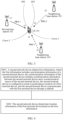
- FIG. 1 is a diagram of a wireless communication system 100 applicable to an embodiment of this application.
- the communication system 100 includes a terminal device (represented as a UE in FIG. 1 ), a radio access network (represented as a next generation radio access network (next generation radio access network, NG-RAN) in FIG. 1 ), and a core network.
- a terminal device represented as a UE in FIG. 1
- a radio access network represented as a next generation radio access network (next generation radio access network, NG-RAN) in FIG. 1
- NG-RAN next generation radio access network
- the radio access network includes one or more next generation evolved NodeBs (next generation evolved NodeBs, ng-eNBs) and gNBs.
- the ng-eNB represents an LTE base station that accesses a 5G core network
- the gNB represents a 5G base station that accesses the 5G core network.
- Communication between an ng-eNB and a gNB, two ng-eNBs, or two gNBs is performed through an Xn interface.
- the Xn interface may also be referred to as an XnAP interface.
- the radio access network is connected to the core network through an NG-C interface.
- the core network includes other functions such as an access and mobility management function (access and mobility management function, AMF) and a location management function (location management function, LMF).
- AMF access and mobility management function
- LMF location management function
- the LMF is responsible for supporting different types of location services related to the UE, including positioning the UE and transferring assistance data to the UE.
- the LMF may perform signal interaction with the UE and the RAN, for example, the ng-eNB or the gNB.
- the LMF performs information interaction with the ng-eNB or the gNB through a new radio positioning protocol annex (new radio positioning protocol annex, NRPPa) message, for example, obtaining a reference signal (positioning reference signal, PRS), configuration information of a sounding reference signal (sounding reference signal, SRS), cell timing, cell location information, and the like.
- UE capability information, assistance information, measurement information, and the like are transferred between the LMF and the UE through an LTE positioning protocol (LTE positioning protocol, LPP) message.
- LTE positioning protocol LTE positioning protocol
- the AMF entity may receive a location service request related to the UE from a location service (location service, LCS) entity of the 5G core network (5G core, 5GC).
- LCS location service
- 5G core 5G core
- the AMF may start some location services on behalf of a specific UE, and forward a location service request to the LMF.
- the terminal device is connected to the radio access network via the ng-eNB through an LTE-Uu interface.
- the terminal device may alternatively be connected to the radio access network via the gNB through an NR-Uu interface.
- the communication system 100 may include one or more base stations (including the ng-eNB or the gNB). It should be further understood that the communication system 100 may include one or more terminal devices, for example, one or more terminal device groups (for example, a UE set shown in FIG. 1 ).
- One gNB may send data or control signaling to one or more terminal devices.
- a plurality of gNBs may send data or control signaling to one terminal device at the same time.
- the ng-eNB and the gNB in FIG. 1 may also be replaced with a TRP, a TP, a reception point (reception point, RP), a cell, and the like.
- FIG. 2 is a diagram of a wireless communication system 200 applicable to an embodiment of this application.
- the wireless communication system 200 may include at least one terminal device, for example, a UE 101 shown in FIG. 2 .
- the wireless communication system 200 may further include a plurality of network devices (where for example, the network devices may be base stations (base stations, BSs) or TRPs, and the base stations are used as an example below).
- the plurality of base stations include a base station of a serving cell of the terminal device 101 and base stations of one or more neighboring cells of the serving cell.
- the base station of the serving cell (which may also be referred to as a serving base station) is 102 shown in FIG.
- a plurality of antennas may be configured for both the network device and the terminal device, and the network device may communicate with the terminal device by using a multi-antenna technology.
- a base station in FIG. 2 may be replaced with a TRP, a TP, an RP, a cell, or the like.
- the wireless communication system 200 may further include an LMF network element 105.
- the LMF network element 105 may be configured to estimate a location of the terminal device.
- the LMF network element 105 may be deployed inside a core network, that is, the LMF network element 105 is also a core network element.
- the LMF network element 105 may communicate with the network device via an AMF network element (not shown in the figure).
- AMF network element not shown in the figure.
- sending of information to the network device by the LMF network element through the AMF network element is referred to as sending of information to the network device by the LMF network element for short.
- the LMF network element sends a message to the network device may be understood as that the LMF network element first sends information to the AMF network element and the AMF network element forwards the information to the network device.
- the LMF network element may directly send the information to the network device.
- some functions of the LMF network element 105 may be integrated in the network device.
- a location management component location management component, LMC
- the base station 102 of the serving cell and the base stations 103 and 104 of the two neighboring cells are each integrated with the LMC. That the LMC of the LMF network element integrated in the network device sends information to the network device may also be considered as that the LMF network element sends the information to the network device.
- the architecture of the communication system shown in FIG. 2 is merely used as an example, and use of another architecture is not limited.
- the base station 102 of the serving cell and the base stations 103 and 104 of the two neighboring cells are shown in FIG. 2 .
- the communication system 200 may further include base stations of more neighboring cells.
- the LMF network element communicates with the base station according to an NRPPa protocol.
- the LMF network element communicates with the UE according to an LPP protocol.
- the LMF performs cell information interaction with the base station according to the NRPPa protocol, for example, configuration information of a reference signal of a cell, cell timing information, and geographical location information of the cell.
- the UE capability information, the assistance information, the measurement information, and the like are transferred between the LMF and the UE according to the LPP protocol.
- the interface is a communication interface between a terminal and a base station.
- Uu communication requires participation of the base station and cellular network coverage.
- the interface is characterized by long-distance and large-scale reliable communication.
- a PC5 interface and the Uu interface can coexist.
- the interface is a communication interface between terminals, to be specific, a short-distance direct communication interface between a vehicle, a person, and a road infrastructure.
- PC5 communication does not require cellular network coverage and can be used for point-to-point communication.
- the interface is characterized by low-latency, high-capacity, and highly-reliable communication through direct connection, broadcast, and network scheduling.
- a direct communication link used in the PC5 interface is referred to as a sidelink (sidelink, SL).
- RRC idle mode RRC_IDLE
- RRC inactive mode RRC_INACTIVE
- RRC connected mode RRC_CONNECTED
- a target UE may be positioned by using a positioning technology, so that a positioning initiator that initiates a positioning service obtains location information of the target UE.
- the positioning initiator may be an LCS, a UE, an AMF network element, or the like.
- the LCS requests a serving AMF of the target UE to position the target UE; or a serving AMF of the target UE decides to position the target UE; or the target UE requests a positioning service from a serving AMF of the target UE, for example, initiates the request due to positioning or transmission of assistance information.
- an LMF After the positioning service is triggered, an LMF further performs a positioning-related operation.
- the LMF needs to perform interaction with the base station, for example, obtaining assistance information related to air interface positioning.
- the LMF further needs to perform interaction with the target UE, for example, a capability transmission procedure, including obtaining a positioning capability of the UE, providing positioning-related assistance information for the UE, and the like.
- the target UE may send and/or receive a Uu interface-based positioning-related reference signal for positioning, and the target UE is positioned by using a positioning method supported in NR and LTE.
- the Uu interface-based positioning-related reference signal includes a PRS and/or an SRS.
- the PRS is a downlink signal
- the SRS is an uplink signal.
- a common positioning method for a cellular network is a TDOA.
- the TDOA includes a downlink time difference of arrival (downlink time difference of arrival, DL-TDOA) positioning method and an uplink time difference of arrival (uplink time difference of arrival, UL-TDOA) positioning method.
- DL-TDOA downlink time difference of arrival
- uplink time difference of arrival uplink time difference of arrival
- UL-TDOA uplink time difference of arrival
- a base station in FIG. 3 may be replaced with a TRP, a TP, an RP, a cell, or the like.
- a principle of the DL-TDOA is that a target UE receives downlink signals (for example, PRSs) from a plurality of TPs, and the target UE measures, by using assistance data (assistance data) received from an LMF, a DL RSTD (reference signal time difference, reference signal time difference) between the PRSs sent by the plurality of TPs, and calculates location information of the target UE based on the DL RSTD.
- the plurality of TPs include one reference TP.
- the reference TP corresponds to a serving base station of the target UE.
- the plurality of TPs further include at least two neighboring TPs.
- the DL RSTD is a downlink relative timing difference (DL relative timing difference) between a neighboring TP and the reference TP.
- the downlink relative timing difference may be defined as time A minus time B.
- the time A is time when the target UE receives a start of one subframe from the neighboring TP.
- the time B is time when the target UE receives a corresponding start of one subframe from the reference TP, where the subframe is closest in time to the subframe received from the neighboring TP.
- FIG. 3 is a diagram of the DL-TDOA positioning method. An example is shown in FIG. 3 .
- a serving base station 102 sends a PRS 1 to the UE 101 at t1', and the UE 101 receives the PRS 1 at a moment t1.
- a neighboring base station 103 sends a PRS 2 to the UE 101 at t2', and the UE 101 receives the PRS 2 at a moment t2.
- a neighboring base station 104 sends a PRS 3 to the UE 101 at t3', and the UE 101 receives the PRS 3 at a moment t3.
- FIG. 3 is a diagram of the DL-TDOA positioning method. An example is shown in FIG. 3 .
- a difference between distances from any point on a curve 1 to the serving base station 102 and the neighboring base station 103 is a fixed value ⁇ S2
- a difference between distances from any point on a curve 2 to the serving base station 102 and the neighboring base station 104 is a fixed value ⁇ S3
- an intersection point of the curve 1 and the curve 2 is a location of the UE 101.
- the location information of the UE 101 can be calculated.
- both the neighboring base station 103 and the neighboring base station 104 are neighboring TPs, and the serving base station 102 is a reference TP.
- RSTD 1, 2 represents a DL RSTD between the PRSs sent by the serving base station 102 and the neighboring base station 103
- RSTD 1, 3 represents a DL RSTD between the PRSs sent by the serving base station 102 and the neighboring base station 104.
- the LMF may calculate the location information of the target UE. This may be referred to as LMF-based or UE-assisted. As shown in FIG. 3 , if the LMF-based is used, the target UE and/or the base station need/needs to report, to the LMF, the DL RSTD between the PRSs received by the target UE from the plurality of base stations, and the LMF calculates the location information of the target UE based on the DL RSTD reported by the UE and/or the base station.
- the target UE may also calculate the location information of the target UE. This may be referred to as UE-based. As shown in FIG. 3 , if the UE-based is used, the target UE may calculate the location information of the target UE based on the DL RSTD between the PRSs received from the plurality of base stations.
- the RSTD in the foregoing Formula (1) and Formula (2) may also be determined by a receiving subframe boundary difference between each neighboring TP and the reference TP.
- the receiving subframe boundary difference is the RSTD.
- the receiving subframe boundary difference may be understood as a subframe boundary difference between the plurality of TPs on the target UE side, or may be understood as a subframe boundary difference between the plurality of TPs.
- a manner of calculating the receiving subframe boundary difference refer to the foregoing manner of calculating the DL RSTD, for example, time when the target UE receives a start of one subframe from the neighboring TP minus time when the target UE receives a corresponding start of one subframe from the reference TP, where the subframe is closest in time to the subframe received from the neighboring TP.
- a PRS sending time difference in the foregoing Formula (1) and Formula (2) may be represented by a sending subframe boundary difference between each neighboring TP and the reference TP.
- the sending subframe boundary difference is the PRS sending time difference.
- the sending subframe boundary difference may also be understood as a subframe boundary difference between the plurality of TPs.
- a manner of calculating the sending subframe boundary difference refer to the foregoing manner of calculating the DL RSTD, for example, time when the neighboring TP sends a start of one subframe to the target UE minus time when the reference TP sends a corresponding start of one subframe to the target UE, where the subframe is closest in time to the subframe sent by the neighboring TP.
- the subframe boundary difference may be replaced with a frame boundary difference. It may be understood that the boundary difference may be replaced with a time difference between boundaries.
- RSTD 1, 2 in Formula (1) may be reported by the UE 101 to the LMF, t1' may be determined by the LMF based on configuration information of the PRS 1 of the serving base station 102, and t2' may be determined by the LMF based on configuration information of the PRS 2 of the neighboring base station 103; or t1' is a subframe boundary of the serving base station 102, and t2' is a subframe boundary of the neighboring base station 103, that is, t2'-t1' may be obtained based on a difference between the subframe boundaries of the neighboring base station 103 and the serving base station 102.
- RSTD 1, 3 in Formula (2) may be reported by the UE 101 to the LMF, t1' may be obtained by the LMF from the configuration information of the PRS 1 of the serving base station 102, and t3' may be obtained by the LMF from configuration information of the PRS 3 of the neighboring base station 104; or t1' is the subframe boundary of the serving base station 102, and t3' is a subframe boundary of the neighboring base station 104, that is, t3'-t1' may be obtained based on a difference between the subframe boundaries of the neighboring base station 104 and the serving base station 102.
- RSTD 1, 2 in Formula (1) may be obtained by the UE through measurement, t1' may be determined by the UE 101 based on configuration information of the PRS 1 that is sent by the LMF, and t2' may be determined by the UE 101 based on configuration information of the PRS 2 that is sent by the LMF; or t1' is a subframe boundary of the serving base station 102, t2' is a subframe boundary of the neighboring base station 103, and t2'-t1' may be obtained based on a difference between the subframe boundaries of the serving base station 102 and the neighboring base station 103.
- RSTD 1, 3 in Formula (2) may be obtained by the UE 101 through measurement, t1' may be determined by the UE based on the configuration information of the PRS 1 that is sent by the LMF, and t3' may be determined by the UE 101 based on configuration information of the PRS 3 that is sent by the LMF; or t1' is the subframe boundary of the serving base station 102, t3' is a subframe boundary of the neighboring base station 104, and t3'-t1' may be obtained based on a difference between the subframe boundaries of the serving base station 102 and the neighboring base station 104.
- a principle of the UL-TDOA positioning method is to calculate the location information of the target UE based on a UL relative time of arrival (relative time of arrival, RTOA) of an uplink signal (for example, an SRS) sent by the target UE to a plurality of RPs.
- the UL-RTOA is a beginning of a subframe including the uplink signal received at the RP relative to an RTOA.
- the RP measures the UL-RTOA of the received signal (for example, the SRS) by using assistance data obtained from a location server.
- the LMF calculates the location information of the UE based on a time difference between receiving, by the plurality of RPs, the SRS sent by the UE.
- a current positioning method is mainly used to perform positioning based on a reference signal of a Uu interface.
- a sidelink is used in a Uu interface-based positioning scenario, to be specific, at least one network element, terminal, or entity (for example, a road side unit (road side unit, RSU)) that can send a reference signal of a PC5 interface is used in the positioning scenario, the target UE needs to be positioned based on the reference signal of the Uu interface and the sidelink reference signal of the PC5 interface in the positioning scenario, or the target UE needs to be positioned based only on the sidelink reference signal of the PC5 interface in the positioning scenario.
- a road side unit road side unit
- the LMF or the target UE cannot accurately obtain the location information of the target UE through calculation.
- an example is used herein for description.
- the neighboring base station 104 is replaced with the RSU, and the RSU may send the sidelink reference signal of the PC5 interface (where an example in which the sidelink reference signal of the PC5 interface is an SL-PRS is used below).
- the sidelink reference signal of the PC5 interface is an SL-PRS is used below.
- the UE 101 needs to be positioned based on the reference signal of the Uu interface and the sidelink reference signal of the PC5 interface. Because a manner of determining, by the LMF or the UE 101, the time (namely, t3') for sending the PRS 3 by the neighboring base station 104 is different from a manner of determining sending time for sending the SL-PRS by the RSU, the LMF or the UE 101 cannot accurately obtain the location information of the UE 101 through calculation.
- the location information of the target UE may be calculated by the target UE, or may be calculated by the LMF.
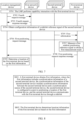
- FIG. 4 is a schematic flowchart of a positioning method according to an embodiment of this application.
- an LMF calculates location information of a target UE.
- the method may include the following steps.
- a second network device obtains first information, where the first information includes synchronization information of a second terminal device, the synchronization information of the second terminal device includes synchronization information between the second terminal device and a synchronization source of the second terminal device, the second terminal device is configured to assist in positioning a location of a first terminal device, and the second terminal device communicates with the first terminal device through a sidelink.
- the second network device in this embodiment of this application is a device having a location management function.
- the second network device may be a part of a core network, or may be integrated into a network device.
- the second network device may be the LMF shown in FIG. 1 or FIG. 2 , or a location management component (location management component, LMC) in a serving network device of a to-be-positioned terminal device.
- LMC location management component
- the second network device may also be referred to as a location management device or a location center.
- a name of the location management device is not limited in this application. In a future evolved technology, the location management device may also be assigned another name.
- an example in which the second network device is a location management device is used for description.
- the first terminal device is the target UE.
- the first terminal device may be considered as the UE 101
- the second terminal device may be considered as the RSU
- the location management device may be considered as the LMF 105.
- one or more second terminal devices that assist in positioning the location of the first terminal device may be included in a scenario. This is not limited in this application. That the second terminal device is configured to assist in positioning a location of a first terminal device may be understood as that the first terminal device receives a sidelink reference signal from the second terminal device, and/or the first terminal device sends a sidelink reference signal to the second terminal device to assist the location management device in positioning the location of the first terminal device.
- the synchronization information of the second terminal device includes a time difference between a subframe boundary of the second terminal device and a subframe boundary of the serving network device of the second terminal device.
- the time difference between the subframe boundary of the second terminal device and the subframe boundary of the serving network device of the second terminal device may be a time difference between a downlink subframe boundary of the second terminal device and a downlink subframe boundary of the serving network device of the second terminal device, or may be a time difference between an uplink subframe boundary of the second terminal device and an uplink subframe boundary of the serving network device of the second terminal device.
- the time difference between the subframe boundary of the second terminal device and the subframe boundary of the serving network device of the second terminal device includes timing advance (timing advance, TA) information of the second terminal device.
- timing advance timing advance
- the synchronization information of the second terminal device is TA/2.
- the synchronization information of the second terminal device includes a time difference between a subframe boundary of the second terminal device and a subframe boundary of the serving network device of the second terminal device.
- the synchronization information of the second terminal device may be determined by a distance between the second terminal device and the serving network device of the second terminal device. For example, information about the distance between the second terminal device and the serving network device of the second terminal device, location information of the second terminal device, or the like is determined by using a positioning method between the second terminal device and the serving network device of the second terminal device.
- the positioning method may be any positioning method such as a multi-cell round trip time (multi-cell round trip time, Multi-RTT), a UL-TDOA, or a DL-TDOA.
- the synchronization information of the second terminal device may be obtained based on the information about the distance between the second terminal device and the serving network device of the second terminal device, the location information of the second terminal device, or the like.
- the synchronization information of the second terminal device includes a direct frame number (direct frame number, DFN) offset (offsetDFN) of the second terminal device.
- DFN direct frame number
- the location management device may obtain the first information by using any one of the following methods.
- Method 1 The location management device receives the first information from the second terminal device.
- that the location management device obtains the first information mainly includes the following steps.
- Method 2 The location management device receives the first information from the serving network device of the second terminal device. It may be understood that, when the second terminal device is in RRC connected mode, the serving network device of the second terminal device knows the synchronization information of the second terminal device, and the location management device can obtain the first information from the serving network device of the second terminal device.
- the location management device receives first information from the serving network device corresponding to each second terminal device. That is, the location management device separately receives synchronization information of the plurality of second terminal devices from the plurality of network devices.
- the serving network device of the second terminal device may report the first information based on a request of the location management device.
- that the location management device obtains the first information mainly includes the following steps.
- the serving network device of the second terminal device actively reports the first information to the location management device.
- that the location management device obtains the first information mainly includes the following steps.
- the configuration information of the sidelink reference signal may include at least one of the following: a resource configuration of the sidelink reference signal, for example, a time domain resource or a frequency domain resource, and for another example, a 1 st symbol in a slot, a quantity of symbols, a comb offset of the 1 st symbol, and a slot offset of a 1 st slot in a resource set; information such as a periodicity of the sidelink reference signal; a staggering pattern (Staggering pattern); a quantity of repetitions of the sidelink reference signal; and a muting (muting) configuration of the sidelink reference signal.
- a resource configuration of the sidelink reference signal for example, a time domain resource or a frequency domain resource, and for another example, a 1 st symbol in a slot, a quantity of symbols, a comb offset of the 1 st symbol, and a slot offset of a 1 st slot in a resource set
- information such as a periodicity of the sidelink reference signal; a
- the serving network device of the second terminal device sends a fourth request response message to the location management device.
- the fourth request response message includes the configuration information of the sidelink reference signal of the second terminal device and the first information.
- the location management device receives the fourth request response message from the serving network device of the second terminal device.
- the serving network device of the second terminal device may also directly send both the configuration information of the sidelink reference signal of the second terminal device and the synchronization information of the second terminal device to the location management device.
- the serving network device of the second terminal device may alternatively separately send the first information and the fourth request response message to the location management device.
- the fourth request response message includes the configuration information of the sidelink reference signal of the second terminal device, and the first information is carried in another message.
- the location management device may also obtain the first information in another implementation or by using the method provided below.
- the serving network device of the second terminal device after receiving the fourth request message, reports the configuration information of the sidelink reference signal of the second terminal device through the fourth request response message, but does not report the synchronization information of the second terminal device. This is not specifically limited in this application.
- the configuration information of the sidelink reference signal of the second terminal device that is included in the fourth request response message may be directly determined by the serving network device of the second terminal device, or may be determined by the second terminal device. The following provides descriptions with reference to FIG. 5 .
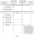
- FIG. 5 is a schematic flowchart of obtaining the configuration information of the sidelink reference signal of the second terminal device by the location management device according to this application.
- FIG. 5 includes procedures corresponding to a determining manner 1 and a determining manner 2.
- the serving network device of the second terminal device directly determines the configuration information of the sidelink reference signal of the second terminal device.
- the determining manner 1 mainly includes the following steps.
- the location management device sends the fourth request message to a first network device.
- the first network device is a serving network device of the second terminal device.
- the first network device receives the fourth request message from the location management device.
- the first network device determines configuration information of sidelink reference signals of one or more second terminal devices within coverage of the first network device.
- the fourth request response message includes the configuration information of the sidelink reference signal of all the second terminal devices within the coverage of the first network device.
- the first network device sends, to each of the one or more second terminal devices within the coverage of the first network device, the configuration information of the sidelink reference signal corresponding to the second terminal device.
- the first network device sends a second message to the second terminal device.
- the second message includes the configuration information of the sidelink reference signal of the second terminal device.
- the first network device separately sends a second message to one of the plurality of second terminal devices.
- the second message includes the configuration information of the sidelink reference signal of the second terminal device.
- the first network device may alternatively send the configuration information of the sidelink reference signals of the plurality of second terminal devices to only one of the plurality of second terminal devices. For example, the first network device sends a second message to the second terminal device.
- the second message includes the configuration information of the sidelink reference signals of the plurality of second terminal devices.
- the plurality of second terminal devices may be second terminal devices requested by the location management device in the fourth request message.
- the location management device sends the fourth request message to a first network device.
- the first network device is a serving network device of the second terminal device.
- the location management device receives the fourth request response message from the first network device.
- the first network device In response to the received fourth request message, the first network device sends a fifth request message to the second terminal device.
- the fifth request message is used to request the configuration information of the sidelink reference signal of the second terminal device.
- the second terminal device receives the fifth request message from the first network device.
- the first network device may send the fifth request message to only the one or more second terminal devices requested by the location management device in the fourth request message.
- the first network device may send the fifth request message to all second terminal devices within coverage of the first network device.
- the second terminal device determines the configuration information of the sidelink reference signal of the second terminal device.
- the second terminal device sends a fifth request response message to the second terminal device.
- the fifth request response message includes the configuration information of the sidelink reference signal of the second terminal device.
- the first network device receives the fifth request response message from the second terminal device.
- S505' The first network device sends the fourth request response message to the location management device.
- the fourth request response message includes the configuration information of the sidelink reference signals of the one or more second terminal devices requested by the location management device in the fourth request message.
- the first terminal device needs to receive or send the sidelink reference signal based on the configuration information of the sidelink reference signal of the second terminal device.
- the foregoing describes how the location management device obtains the configuration information of the sidelink reference signal of the second terminal device.
- the first terminal device obtains the configuration information of the sidelink reference signal of the second terminal device.
- the first terminal device obtains the configuration information of the sidelink reference signal of the second terminal device from the location management device. Specifically, as shown in FIG. 5 , in S510, the location management device sends a first configuration message to the first terminal device.
- the first configuration message includes the configuration information of the sidelink reference signal of the second terminal device.
- the first terminal device receives the first configuration message from the location management device.
- the location management device needs to send the configuration information of the sidelink reference signals of the plurality of second terminal devices to the first terminal device.
- the location management device may separately send the identifier of each of the plurality of second terminal devices and the configuration information of the sidelink reference signal of the second terminal device to the first terminal device, that is, the identifiers of the second terminal devices are in one-to-one correspondence with the configuration information of the sidelink reference signals of the second terminal devices.
- the location management device needs to send the configuration information of the sidelink reference signals of the plurality of second terminal devices to the first terminal device.
- the location management device may send the identifiers of the plurality of second terminal devices and the configuration information of the sidelink reference signal of the second terminal device to the first terminal device.
- the identifiers of the plurality of second terminal devices are in one-to-one correspondence with the configuration information of the sidelink reference signals of the plurality of second terminal devices.
- that the identifiers of the plurality of second terminal devices are in one-to-one correspondence with the configuration information of the sidelink reference signals of the plurality of second terminal devices is described by using an example in which the second terminal devices are RSUs.
- configuration information of sidelink reference signals of the RSUs is carried in a message in a sequence of an RSU #1, an RSU #2, and an RSU #3.
- identifiers of the RSUs also need to be carried in the message in the sequence of the RSU #1, the RSU #2, and the RSU #3.
- configuration information of sidelink reference signals of the RSUs is carried in a message in a sequence of an RSU #2, an RSU #1, and an RSU #3, identifiers of the RSUs also need to be carried in the message in the sequence of the RSU #2, the RSU #1, and the RSU #3.
- the one-to-one correspondence means that the first terminal device needs to determine the configuration information of the sidelink reference signals of the RSU #1, the RSU #2, and the RSU #3 in a corresponding manner.
- the location management device configures a list.
- the list includes a plurality of pieces of configuration information, and each piece of configuration information includes an identifier of an RSU and configuration information of a sidelink reference signal of the RSU.
- the one-to-one correspondence may be implemented in another corresponding manner, and details are not described herein.
- the first configuration message may further include the first information.
- the first terminal device obtains the configuration information of the sidelink reference signal of the second terminal device from the second terminal device.
- the second terminal device sends a second configuration message to the first terminal device.
- the second configuration message includes the configuration information of the sidelink reference signal of the second terminal device.
- the first terminal device receives the second configuration message from the second terminal device.
- the second configuration message may further include the first information.
- a unicast connection is established between the first terminal device and the second terminal device, and the second terminal device sends the configuration information of the sidelink reference signal of the second terminal device to the first terminal device based on the unicast connection.
- no unicast connection is established between the first terminal device and the second terminal device.
- the second terminal device sends the configuration information of the sidelink reference signal of the second terminal device to the first terminal device in a broadcast or multicast manner.
- the second terminal device may further send configuration information of a sidelink reference signal of another second terminal device to the first terminal device. This is not limited in this application.
- the method for obtaining the configuration information of the sidelink reference signal of the second terminal device shown in FIG. 5 is merely an example for description. This embodiment of this application is not limited thereto.
- Method 3 The location management device receives the first information from the first terminal device.
- the first terminal device may obtain the synchronization information of the second terminal device from the second terminal device, and send the synchronization information to the location management device. For example, if a unicast connection has been established between the first terminal device and the second terminal device, the second terminal device sends the synchronization information of the second terminal device to the first terminal device in a unicast manner.
- the synchronization information of the second terminal device may be carried in an RRC reconfiguration message or another RRC dedicated message on a sidelink between the first terminal device and the second terminal device.
- the second terminal device sends the synchronization information of the second terminal device to the first terminal device in a broadcast or multicast manner.
- the first terminal device may report the first information based on a request of the location management device.
- that the location management device obtains the first information mainly includes the following steps.
- the first terminal device actively reports the first information to the location management device.
- that the location management device obtains the first information mainly includes the following steps.
- the first terminal device When the first terminal device reports a measurement result of a first reference signal to the location management device, the first terminal device further reports first information of one or more second terminal devices corresponding to the measurement result at the same time. That is, the first terminal device always reports the measurement result together with the first information to the location management device.
- the first reference signal includes the sidelink reference signal (namely, a reference signal of a PC5 interface) sent by the second terminal device to the first terminal device or the sidelink reference signal sent by the first terminal device to the second terminal device.
- the first reference signal includes an SL-PRS.
- the first reference signal further includes a reference signal (namely, a reference signal of a Uu interface) sent to the first terminal device by a network device that assists in positioning the location of the first terminal device.
- the first reference signal includes the SL-PRS and a DL-PRS.
- the first reference signal further includes the reference signal of the Uu interface that is sent by the first terminal device.
- the first reference signal includes the SL-PRS, the DL-PRS, and the SRS.
- the second network device determines the location information of the first terminal device based on the synchronization information of the second terminal device.
- the second network device (location management device) can accurately calculate the location information of the first terminal device after obtaining the first information.
- the RSU sends an SL-PRS to the UE 101 at a moment T3.
- the serving base station 102 keeps synchronous with the neighboring base station 103 and the neighboring base station 104, or a sending subframe boundary difference between the serving base station 102, the neighboring base station 103, and the neighboring base station 104 is known
- the LMF 105 may determine t3'-t1'.
- the LMF 105 does not know synchronization information of the RSU, and therefore cannot determine T3-t1', that is, cannot accurately calculate the location information of the UE 101.
- the synchronization information of the RSU is obtained, so that the LMF 105 can accurately calculate the location information of the UE 101.
- an RSTD is determined by the sidelink reference signal of the PC5 interface and the reference signal of the Uu interface.
- the neighboring base station 104 is replaced with the RSU.
- RSTD 1, 3 in the foregoing Formula (3) is obtained by the UE based on a sidelink reference signal sent by the RSU and a positioning reference signal sent by the serving base station 102.
- a signal measured by the UE includes not only the downlink reference signal but also the sidelink reference signal.
- RSTD 1, 3 in Formula (3) is not completely the same as a DL RSTD, but reference may be made to the foregoing calculation manner of the DL RSTD.
- RSTD 1, 3 in Formula (3) is a relative timing difference, and the relative timing difference may be defined as time C minus time D.
- the time C is time when the target UE (namely, the UE 101) receives a start of one subframe from the RSU.
- the time D is time when the target UE receives a corresponding start of one subframe from the reference TP (namely, the serving base station 102), where the subframe is closest in time to the subframe received from the RSU.
- the location information of the target UE may be obtained based on the reference signal of the Uu interface and the reference signal of the PC5 interface, or the location information of the target UE may be obtained based only on the sidelink reference signal of the PC5 interface. Details are not described herein again.
- the first terminal device obtains the configuration information of the sidelink reference signal of the second terminal device from the location management device, and the first terminal device obtains the first information from the second terminal device.
- the first terminal device determines the location information of the first terminal device based on the first information and the first measurement result.
- the first reference signal and a specific process of determining the location of the first terminal device refer to the foregoing descriptions. Details are not described herein again.
- the apparatus 1000 further includes a storage unit.
- the storage unit may be configured to store instructions and/or data.
- the processing unit 1200 may read the instructions and/or the data in the storage unit, to enable the apparatus to implement the actions performed by the terminal device in the foregoing method embodiments.
- the apparatus 1000 may be configured to perform the actions performed by the first terminal device in the foregoing method embodiments.
- the apparatus 1000 may be the first terminal device or a component of the first terminal device.
- the transceiver unit 1100 is configured to perform receiving/sending-related operations on the first terminal device side in the foregoing method embodiments.
- the processing unit 1200 is configured to perform processing-related operations on the first terminal device side in the foregoing method embodiments.
- the transceiver unit 1100 obtains first information.
- the first information includes synchronization information of a second terminal device.
- the synchronization information of the second terminal device includes synchronization information between the second terminal device and a synchronization source of the second terminal device.
- the second terminal device is configured to assist in positioning a location of the first terminal device.
- the second terminal device communicates with the first terminal device through a sidelink.
- the processing unit 1200 is configured to determine location information of the first terminal device based on the first information.
- the transceiver unit 1100 is specifically configured to receive the first information from a second network device of a location management function network element.
- the transceiver unit 1100 is specifically configured to receive the first information from the second terminal device.
- the transceiver unit 1100 is specifically configured to receive a first configuration message from the second network device of the location management function network element.
- the first configuration message includes configuration information of a sidelink reference signal of the second terminal device.
- the configuration information of the sidelink reference signal of the second terminal device is used by the first terminal device to receive the sidelink reference signal of the second terminal device.
- the first configuration message further includes the first information.
- the transceiver unit 1100 is further configured to send a first message to the second network device of the location management function network element.
- the first message includes an identifier of the second terminal device.
- the second terminal device is a group of terminal devices, and the group of terminal devices includes one or more terminal devices.
- the apparatus 1000 may implement the steps or the procedures performed by the first terminal device in the method embodiments according to embodiments of this application.
- the apparatus 1000 may include units configured to perform the method performed by the first terminal device in the embodiments shown in FIG. 4 to FIG. 10 .
- a specific process in which each unit performs the foregoing corresponding steps has been described in detail in the foregoing method embodiments. For brevity, details are not described herein again.
- the transceiver unit 1100 is specifically configured to receive the first information from the second terminal device.
- the transceiver unit 1100 is specifically configured to receive a second configuration message from the second terminal device.
- the second configuration message includes configuration information of a sidelink reference signal of the second terminal device.
- the configuration information of the sidelink reference signal of the second terminal device is used by the first terminal device to receive the sidelink reference signal of the second terminal device.
- the second configuration message further includes the first information.
- the transceiver unit 1100 is further configured to send a first message to the second network device of the location management function network element.
- the first message includes an identifier of the second terminal device.
- the second terminal device is a group of terminal devices, and the group of terminal devices includes one or more terminal devices.
- the apparatus 1000 may implement the steps or the procedures performed by the first terminal device in the method embodiments according to embodiments of this application.
- the apparatus 1000 may include units configured to perform the method performed by the first terminal device in the embodiments shown in FIG. 4 to FIG. 10 .
- a specific process in which each unit performs the foregoing corresponding steps has been described in detail in the foregoing method embodiments. For brevity, details are not described herein again.
- the apparatus 1000 may be configured to perform the actions performed by the second network device in the foregoing method embodiments.
- the apparatus 1000 may be the second network device or a component of the second network device.
- the transceiver unit 1100 is configured to perform receiving/sending-related operations on the second network device side in the foregoing method embodiments.
- the processing unit 1200 is configured to perform processing-related operations on the second network device side in the foregoing method embodiments.
- the transceiver unit 1100 is configured to obtain first information.
- the first information includes synchronization information of a second terminal device.
- the synchronization information of the second terminal device includes synchronization information between the second terminal device and a synchronization source of the second terminal device.
- the second terminal device is configured to assist in positioning a location of a first terminal device.
- the second terminal device communicates with the first terminal device through a sidelink.
- the processing unit 1200 is configured to determine location information of the first terminal device based on the synchronization information of the second terminal device.
- the transceiver unit 1100 is specifically configured to receive the first information from the second terminal device.
- the transceiver unit 1100 is specifically configured to receive the first information from a serving network device of the second terminal device.
- the transceiver unit 1100 is specifically configured to receive the first information from the first terminal device.
- the transceiver unit 1100 is further configured to send a first request message to the second terminal device.
- the first request message is used to request the synchronization information of the second terminal device.
- the transceiver unit 1100 is further configured to receive a first request response message from the second terminal device.
- the first request response message includes the first information.
- the transceiver unit 1100 is further configured to send a second request message to the serving network device of the second terminal device.
- the second request message is used to request the synchronization information of the second terminal device.
- the transceiver unit 1100 is further configured to receive a second request response message from the serving network device of the second terminal device.
- the second request response message includes the first information.
- the transceiver unit 1100 is further configured to send a third request message to the first terminal device.
- the third request message is used to request the synchronization information of the second terminal device.
- the transceiver unit 1100 is further configured to receive a third request response message from the first terminal device.
- the third request response message includes the first information.
- the transceiver unit 1100 is further configured to send a fourth request message to a serving network device of the second terminal device.
- the fourth request message is used to request to configure configuration information of a sidelink reference signal of the second terminal device.
- the configuration information of the sidelink reference signal of the second terminal device is used by the first terminal device to receive the sidelink reference signal of the second terminal device.
- the transceiver unit 1100 is further configured to receive a fourth request response message from the serving network device of the second terminal device.
- the fourth request response message includes the configuration information of the sidelink reference signal of the second terminal device.
- the fourth request response message includes the first information.
- the transceiver unit 1100 is further configured to send a first configuration message to the first terminal device.
- the first configuration message includes configuration information of a sidelink reference signal of the second terminal device.
- the configuration information of the sidelink reference signal of the second terminal device is used by the first terminal device to receive the sidelink reference signal of the second terminal device.
- the first configuration message further includes the first information.
- the transceiver unit 1100 is further configured to receive a first message from the first terminal device.
- the first message includes an identifier of the second terminal device.
- the transceiver unit 1100 is further configured to send first indication information to a third terminal device.
- the first indication information indicates the third terminal device not to send a reference signal to the first terminal device.
- the third terminal device is a terminal device other than the second terminal device in all terminal devices covered by all network devices that the second network device requests to assist in positioning a target terminal.
- the second terminal device is a group of terminal devices, and the group of terminal devices includes one or more terminal devices.
- the apparatus 1000 may implement the steps or the procedures performed by the second network device in the method embodiments according to embodiments of this application.
- the apparatus 1000 may include units configured to perform the method performed by the second network device in the embodiments shown in FIG. 4 to FIG. 10 .
- a specific process in which each unit performs the foregoing corresponding steps has been described in detail in the foregoing method embodiments. For brevity, details are not described herein again.
- the transceiver unit 1100 is configured to obtain first information.
- the first information includes synchronization information of a second terminal device.
- the synchronization information of the second terminal device includes synchronization information between the second terminal device and a synchronization source of the second terminal device.
- the second terminal device is configured to assist in positioning a location of a first terminal device.
- the second terminal device communicates with the first terminal device through a sidelink.
- the transceiver unit 1100 is further configured to send the first information to the first terminal device.
- the transceiver unit 1100 is specifically configured to receive the first information from the second terminal device.
- the transceiver unit 1100 is specifically configured to receive the first information from a serving network device of the second terminal device.
- the transceiver unit 1100 is further configured to send a first request message to the second terminal device.
- the first request message is used to request the synchronization information of the second terminal device.
- the transceiver unit 1100 is further configured to receive a first request response message from the second terminal device.
- the first request response message includes the first information.
- the transceiver unit 1100 is further configured to send a fourth request message to a serving network device of the second terminal device.
- the fourth request message is used to request to configure configuration information of a sidelink reference signal of the second terminal device.
- the configuration information of the sidelink reference signal of the second terminal device is used by the first terminal device to receive the sidelink reference signal of the second terminal device.
- the transceiver unit 1100 is further configured to receive a fourth request response message from the serving network device of the second terminal device.
- the fourth request response message includes the configuration information of the sidelink reference signal of the second terminal device.
- the fourth request response message includes the first information.
- the transceiver unit 1100 is further configured to send a first configuration message to the first terminal device.
- the first configuration message includes configuration information of a sidelink reference signal of the second terminal device.
- the configuration information of the sidelink reference signal of the second terminal device is used by the first terminal device to receive the sidelink reference signal of the second terminal device.
- the first configuration message further includes the first information.
- the transceiver unit 1100 is further configured to receive a first message from the first terminal device.
- the first message includes an identifier of the second terminal device.
- the transceiver unit 1100 is further configured to send first indication information to a third terminal device.
- the first indication information indicates the third terminal device not to send a reference signal to the first terminal device.
- the third terminal device is a terminal device other than the second terminal device in all terminal devices covered by all network devices that the second network device requests to assist in positioning a target terminal.
- the second terminal device is a group of terminal devices, and the group of terminal devices includes one or more terminal devices.
- the apparatus 1000 may implement the steps or the procedures performed by the second network device in the method embodiments according to embodiments of this application.
- the apparatus 1000 may include units configured to perform the method performed by the second network device in the embodiments shown in FIG. 4 to FIG. 10 .
- a specific process in which each unit performs the foregoing corresponding steps has been described in detail in the foregoing method embodiments. For brevity, details are not described herein again.
- the apparatus 1000 may be configured to perform the actions performed by the first network device in the foregoing method embodiments.
- the apparatus 1000 may be the first network device or a component of the first network device.
- the transceiver unit 1100 is configured to perform receiving/sending-related operations on the first network device side in the foregoing method embodiments.
- the processing unit 1200 is configured to perform processing-related operations on the first network device side in the foregoing method embodiments.
- the transceiver unit 1100 is configured to obtain first information.
- the first information includes synchronization information of a second terminal device.
- the first network device is a serving network device of the second terminal device.
- the second terminal device is configured to assist in positioning a location of a first terminal device.
- the second terminal device communicates with the first terminal device through a sidelink.
- the transceiver unit 1100 is further configured to send the first information to a second network device.
- the transceiver unit 1100 is further configured to receive a second request message from the second network device.
- the second request message is used to request the synchronization information of the second terminal device.
- the transceiver unit 1100 is further configured to send a second request response message to the second network device.
- the second request response message includes the first information.
- the transceiver unit 1100 is further configured to receive a fourth request message from the second network device.
- the fourth request message is used to request to configure configuration information of a sidelink reference signal of the second terminal device.
- the configuration information of the sidelink reference signal of the second terminal device is used by the first terminal device to receive the sidelink reference signal of the second terminal device.
- the transceiver unit 1100 is further configured to send a fourth request response message to the second network device.
- the fourth request response message includes the configuration information of the sidelink reference signal of the second terminal device.
- the fourth request response message further includes the first information.
- the transceiver unit 1100 is further configured to send a second message to the second terminal device.
- the second message includes the configuration information of the sidelink reference signal of the second terminal device.
- the transceiver unit 1100 is further configured to send a fifth request message to the second terminal device.
- the fifth request message is used to request the configuration information of the sidelink reference signal of the second terminal device.
- the transceiver unit 1100 is further configured to receive a fifth request response message from the second terminal device.
- the fifth request response message includes the configuration information of the sidelink reference signal of the second terminal device.
- the second terminal device is a group of terminal devices, and the group of terminal devices includes one or more terminal devices.
- the apparatus 1000 may implement the steps or the procedures performed by the first network device in the method embodiments according to embodiments of this application.
- the apparatus 1000 may include units configured to perform the method performed by the first network device in the embodiments shown in FIG. 4 to FIG. 10 .
- a specific process in which each unit performs the foregoing corresponding steps has been described in detail in the foregoing method embodiments. For brevity, details are not described herein again.
- the apparatus 1000 may be configured to perform the actions performed by the second terminal device in the foregoing method embodiments.
- the apparatus 1000 may be the second terminal device or a component of the second terminal device.
- the transceiver unit 1100 is configured to perform receiving/sending-related operations on the second terminal device side in the foregoing method embodiments.
- the processing unit 1200 is configured to perform processing-related operations on the second terminal device side in the foregoing method embodiments.
- the processing unit 1200 is configured to determine synchronization information of the second terminal device.
- the synchronization information of the second terminal device includes synchronization information between the second terminal device and a synchronization source of the second terminal device.
- the transceiver unit 1100 is configured to send first information to a first device.
- the first information includes the synchronization information of the second terminal device.
- the second terminal device is configured to assist in positioning a location of a first terminal device.
- the second terminal device communicates with the first terminal device through a sidelink.
- the first device is the first terminal device or a second network device of a location management function network element.
- the transceiver unit 1100 is further configured to receive a first request message from the first device.
- the first request message is used to request the synchronization information of the second terminal device.
- the transceiver unit 1100 is further configured to send a first request response message to the first device.
- the first request response message includes the first information.
- the transceiver unit 1100 is further configured to send a second configuration message to the first device.
- the second configuration message includes configuration information of a sidelink reference signal of the second terminal device.
- the configuration information of the sidelink reference signal of the second terminal device is used by the first terminal device to receive the sidelink reference signal of the second terminal device.
- the second configuration message further includes the first information.
- the transceiver unit 1100 is further configured to receive a second message from a serving network device of the second terminal device.
- the second message includes the configuration information of the sidelink reference signal of the second terminal device.
- the transceiver unit 1100 is further configured to receive a fifth request message from a serving network device of the second terminal device.
- the fifth request message is used to request the configuration information of the sidelink reference signal of the second terminal device.
- the transceiver unit 1100 is further configured to send a fifth request response message to the serving network device of the second terminal device.
- the fifth request response message includes the configuration information of the sidelink reference signal of the second terminal device.
- the apparatus 1000 may implement the steps or the procedures performed by the second terminal device in the method embodiments according to embodiments of this application.
- the apparatus 1000 may include units configured to perform the method performed by the second terminal device in the embodiments shown in FIG. 4 to FIG. 10 .
- a specific process in which each unit performs the foregoing corresponding steps has been described in detail in the foregoing method embodiments. For brevity, details are not described herein again.
- the apparatus 1000 herein is embodied in a form of a functional unit.
- the term "unit" herein may refer to an application-specific integrated circuit (application-specific integrated circuit, ASIC), an electronic circuit, a processor (for example, a shared processor, a dedicated processor, or a group processor) configured to execute at least one software or firmware program and a memory, a combined logic circuit, and/or another suitable component that supports the described functions.
- ASIC application-specific integrated circuit
- ASIC application-specific integrated circuit
- a processor for example, a shared processor, a dedicated processor, or a group processor
- the apparatus 1000 may be specifically the first terminal device in the foregoing embodiments, and may be configured to perform the procedures and/or steps corresponding to the first terminal device in the foregoing method embodiments.
- the apparatus 1000 may be specifically the second network device in the foregoing embodiments, and may be configured to perform the procedures and/or steps corresponding to the second network device in the foregoing method embodiments.
- the apparatus 1000 may be specifically the first network device in the foregoing embodiments, and may be configured to perform the procedures and/or steps corresponding to the first network device in the foregoing method embodiments.
- the apparatus 1000 may be specifically the second terminal device in the foregoing embodiments, and may be configured to perform the procedures and/or steps corresponding to the second terminal device in the foregoing method embodiments. To avoid repetition, details are not described herein again.
- the apparatus 1000 in the foregoing solutions has functions of implementing corresponding steps performed by the devices in the foregoing methods.
- the functions may be implemented by hardware, or may be implemented by hardware executing corresponding software.
- the hardware or the software includes at least one module corresponding to the foregoing functions.
- the transceiver unit may be replaced with a transceiver (where for example, a sending unit in the transceiver unit may be replaced with a transmitter, and a receiving unit in the transceiver unit may be replaced with a receiver), and another unit such as the processing unit may be replaced with a processor, respectively performing the receiving/sending operations and the processing-related operations in the method embodiments.
- the transceiver unit 1100 may alternatively be a transceiver circuit (which may include, for example, a receiving circuit and a sending circuit), and the processing unit may be a processing circuit.
- the apparatus in FIG. 11 may be the device in the foregoing embodiments, or may be a chip or a chip system, for example, a system on chip (system on chip, SoC).
- the transceiver unit may be an input/output circuit or a communication interface.
- the processing unit is a processor, a microprocessor, or an integrated circuit integrated on the chip. This is not limited herein.
- FIG. 12 is a diagram of a structure of a communication apparatus 10 according to this application.
- the apparatus 10 includes a processor 11.
- the processor 11 is coupled to a memory 12.
- the memory 12 is configured to store a computer program or instructions and/or data.
- the processor 11 is configured to: execute the computer program or the instructions stored in the memory 12, or read the data stored in the memory 12, to perform the method in the foregoing method embodiments.
- processors 11 there are one or more processors 11.
- the memory 12 and the processor 11 are integrated together or separately disposed.
- the apparatus 10 further includes a transceiver 13.
- the transceiver 13 is configured to: receive and/or send a signal.
- the processor 11 is configured to control the transceiver 13 to receive and/or send the signal.
- the apparatus 10 is configured to implement the operations performed by the first terminal device in the foregoing method embodiments.
- the processor 11 is configured to execute the computer program or the instructions stored in the memory 12, to implement the related operations of the first terminal device in the foregoing method embodiments, for example, the methods performed by the first terminal device in the embodiments shown in FIG. 4 to FIG. 10 .
- the apparatus 10 is configured to implement the operations performed by the second network device in the foregoing method embodiments.
- the processor 11 is configured to execute the computer program or the instructions stored in the memory 12, to implement the related operations of the second network device in the foregoing method embodiments, for example, the methods performed by the second network device in the embodiments shown in FIG. 4 to FIG. 10 .
- the apparatus 10 is configured to implement the operations performed by the first network device in the foregoing method embodiments.
- the processor 11 is configured to execute the computer program or the instructions stored in the memory 12, to implement the related operations of the first network device in the foregoing method embodiments, for example, the methods performed by the first network device in the embodiments shown in FIG. 4 to FIG. 10 .
- the apparatus 10 is configured to implement the operations performed by the second terminal device in the foregoing method embodiments.
- the processor 11 is configured to execute the computer program or the instructions stored in the memory 12, to implement the related operations of the second terminal device in the foregoing method embodiments, for example, the methods performed by the second terminal device in the embodiments shown in FIG. 4 to FIG. 10 .
- this application further provides a computer-readable storage medium.
- the computer-readable storage medium stores computer instructions. When the computer instructions are run on a computer, the methods in the method embodiments of this application are performed.
- the application further provides a computer program product.
- the computer program product includes computer program code or instructions. When the computer program code or the instructions are run on a computer, the methods in the method embodiments of this application are performed.
- this application further provides a chip, and the chip includes a processor.
- a memory configured to store a computer program is disposed independent of the chip.
- the processor is configured to execute the computer program stored in the memory, so that the methods in the method embodiments of this application are performed.
- the chip may include a communication interface.
- the communication interface may be an input/output interface, an interface circuit, or the like.
- the chip may include the memory.
- this application further provides a communication system, including one or more devices in the first terminal device, the second network device, the first network device, and the second terminal device in embodiments of this application.
- the processor in embodiments of this application may be an integrated circuit chip, and has a signal processing capability.
- steps in the foregoing method embodiments can be completed by using a hardware integrated logical circuit in the processor, or by using instructions in a form of software.
- the processor may be a central processing unit (central processing unit, CPU), or may be another general-purpose processor, a digital signal processor (digital signal processor, DSP), an application-specific integrated circuit (application-specific integrated circuit, ASIC), a field programmable gate array (field programmable gate array, FPGA) or another programmable logic device, a discrete gate or a transistor logic device, or a discrete hardware component.
- the general-purpose processor may be a microprocessor, or the processor may be any conventional processor or the like.
- the steps of the methods disclosed in embodiments of this application may be directly presented as being performed and completed by a hardware encoding processor, or performed and completed by a combination of hardware and a software module in an encoding processor.
- the software module may be located in a mature storage medium in the art, such as a random access memory, a flash memory, a read-only memory, a programmable read-only memory, an electrically erasable programmable memory, or a register.
- the storage medium is located in the memory, and a processor reads information in the memory and completes the steps in the foregoing methods in combination with hardware of the processor.
- the memory in embodiments of this application may be a volatile memory or a non-volatile memory, or may include both the volatile memory and the non-volatile memory.
- the non-volatile memory may be a read-only memory (read-only memory, ROM), a programmable read-only memory (programmable ROM, PROM), an erasable programmable read-only memory (erasable PROM, EPROM), an electrically erasable programmable read-only memory (electrically EPROM, EEPROM), or a flash memory.
- the volatile memory may be a random access memory (random access memory, RAM), used as an external cache.
- RAMs may be used, for example, a static random access memory (static RAM, SRAM), a dynamic random access memory (dynamic RAM, DRAM), a synchronous dynamic random access memory (synchronous DRAM, SDRAM), a double data rate synchronous dynamic random access memory (double data rate SDRAM, DDR SDRAM), an enhanced synchronous dynamic random access memory (enhanced SDRAM, ESDRAM), a synchlink dynamic random access memory (synchlink DRAM, SLDRAM), and a direct rambus random access memory (direct rambus RAM, DRRAM).
- static random access memory static random access memory
- DRAM dynamic random access memory
- DRAM dynamic random access memory
- SDRAM synchronous dynamic random access memory
- double data rate SDRAM double data rate SDRAM
- DDR SDRAM double data rate SDRAM
- ESDRAM enhanced synchronous dynamic random access memory
- synchlink dynamic random access memory synchlink dynamic random access memory
- direct rambus RAM direct rambus RAM
- the processor is a general-purpose processor, a DSP, an ASIC, an FPGA or another programmable logic device, a discrete gate or a transistor logic device, or a discrete hardware component
- the memory storage module
- the memory described in this specification aims to include but is not limited to these memories and any memory of another suitable type.
- the disclosed system, apparatus, and method may be implemented in other manners.
- the foregoing apparatus embodiments are merely examples.
- the unit division is merely logical function division and may be other division during actual implementation.
- a plurality of units or components may be combined or integrated into another system, or some features may be ignored or not performed.
- the displayed or discussed mutual couplings or direct couplings or communication connections may be implemented through some interfaces.
- the indirect couplings or communication connections between the apparatuses or units may be implemented in an electronic form, a mechanical form, or another form.
- the units described as separate parts may or may not be physically separate, and parts displayed as units may or may not be physical units, that is, may be located in one position, or may be distributed on a plurality of network units. Some or all of the units may be selected based on an actual requirement to achieve the objectives of the solutions of the embodiments.
- the functions When the functions are implemented in the form of a software functional unit and sold or used as an independent product, the functions may be stored in a computer-readable storage medium. Based on such an understanding, the technical solutions of this application essentially, or the part contributing to a conventional technology, or a part of the technical solutions may be implemented in a form of a software product.
- the computer software product is stored in a storage medium and includes several instructions for instructing a computer device (which may be a personal computer, a server, a network device, or the like) to perform all or a part of the steps of the methods in embodiments of this application.
- the foregoing storage medium includes various media that can store program code, for example, a USB flash drive, a removable hard disk, a ROM, a RAM, a magnetic disk, or an optical disc.
Landscapes
- Engineering & Computer Science (AREA)
- Computer Networks & Wireless Communication (AREA)
- Signal Processing (AREA)
- Physics & Mathematics (AREA)
- General Physics & Mathematics (AREA)
- Radar, Positioning & Navigation (AREA)
- Remote Sensing (AREA)
- Mobile Radio Communication Systems (AREA)
Applications Claiming Priority (3)
| Application Number | Priority Date | Filing Date | Title |
|---|---|---|---|
| CN202210555591 | 2022-05-20 | ||
| CN202210728631.XA CN117135561A (zh) | 2022-05-20 | 2022-06-25 | 定位方法和通信装置 |
| PCT/CN2023/094200 WO2023221924A1 (zh) | 2022-05-20 | 2023-05-15 | 定位方法和通信装置 |
Publications (2)
| Publication Number | Publication Date |
|---|---|
| EP4521779A1 true EP4521779A1 (de) | 2025-03-12 |
| EP4521779A4 EP4521779A4 (de) | 2025-08-20 |
Family
ID=88834618
Family Applications (1)
| Application Number | Title | Priority Date | Filing Date |
|---|---|---|---|
| EP23806876.1A Pending EP4521779A4 (de) | 2022-05-20 | 2023-05-15 | Positionierungsverfahren und kommunikationsvorrichtung |
Country Status (4)
| Country | Link |
|---|---|
| US (1) | US20250071723A1 (de) |
| EP (1) | EP4521779A4 (de) |
| JP (1) | JP2025518562A (de) |
| WO (1) | WO2023221924A1 (de) |
Families Citing this family (1)
| Publication number | Priority date | Publication date | Assignee | Title |
|---|---|---|---|---|
| EP4322635A1 (de) * | 2022-08-11 | 2024-02-14 | Robert Bosch GmbH | Verfahren und vorrichtung für ein endgerät |
Family Cites Families (8)
| Publication number | Priority date | Publication date | Assignee | Title |
|---|---|---|---|---|
| US9713117B2 (en) * | 2014-09-25 | 2017-07-18 | Intel Corporation | Device-to-device assisted positioning in wireless cellular technologies |
| WO2021092813A1 (en) * | 2019-11-13 | 2021-05-20 | Nokia Shanghai Bell Co., Ltd. | Accurate sidelink positioning reference signal transmission timing |
| US12571870B2 (en) * | 2020-04-20 | 2026-03-10 | Lg Electronics Inc. | Method and apparatus for positioning terminal in wireless communication system |
| BR112023002513A2 (pt) * | 2020-08-10 | 2023-04-04 | Lenovo Singapore Pte Ltd | Seleção de recurso de enlace lateral autônoma |
| US12021777B2 (en) * | 2020-09-02 | 2024-06-25 | Qualcomm Incorporated | Spatial relationship design for sidelink-assisted positioning |
| CN114205735B (zh) * | 2020-09-03 | 2024-10-18 | 上海朗帛通信技术有限公司 | 一种被用于无线通信的节点中的方法和装置 |
| US11671224B2 (en) * | 2020-09-08 | 2023-06-06 | Qualcomm Incorporated | Sidelink positioning and WLAN-based positioning |
| EP4436275A4 (de) * | 2021-11-16 | 2025-01-15 | Beijing Xiaomi Mobile Software Co., Ltd. | Positionierungsverfahren und -vorrichtung sowie speichermedium |
-
2023
- 2023-05-15 WO PCT/CN2023/094200 patent/WO2023221924A1/zh not_active Ceased
- 2023-05-15 JP JP2024568764A patent/JP2025518562A/ja active Pending
- 2023-05-15 EP EP23806876.1A patent/EP4521779A4/de active Pending
-
2024
- 2024-11-14 US US18/947,956 patent/US20250071723A1/en active Pending
Also Published As
| Publication number | Publication date |
|---|---|
| JP2025518562A (ja) | 2025-06-17 |
| EP4521779A4 (de) | 2025-08-20 |
| WO2023221924A1 (zh) | 2023-11-23 |
| US20250071723A1 (en) | 2025-02-27 |
Similar Documents
| Publication | Publication Date | Title |
|---|---|---|
| US10834695B2 (en) | OTDOA network assistance to MTC/NB-IoT user equipment | |
| TWI760931B (zh) | 資訊傳輸方法、裝置及電腦存儲介質 | |
| US20230199700A1 (en) | Increasing mobile device positioning accuracy | |
| EP4187964A1 (de) | Uplink-signalortungsverfahren, kommunikationsbasisstation, messbasisstation und benutzergerät | |
| EP4460047A1 (de) | Kommunikationsverfahren und kommunikationsvorrichtung | |
| WO2021008581A1 (zh) | 用于定位的方法和通信装置 | |
| US20190261308A1 (en) | Conditional Termination of RSTD Measurements | |
| CN114513832B (zh) | 终端设备定位方法、装置、设备及存储介质 | |
| US11265840B2 (en) | Data transmission and management for positioning mobile devices | |
| EP4301057A1 (de) | Kommunikationsverfahren und -vorrichtung | |
| CN115398855B (zh) | 传播延迟补偿 | |
| EP4535885A1 (de) | Synchronisationsverfahren und -vorrichtung in einem satellitennetzwerk | |
| WO2022083547A1 (zh) | 测量配置方法、设备及系统 | |
| CN117796068A (zh) | 用于指示上行链路信息的系统和方法 | |
| CN114845237B (zh) | 终端的定位方法、装置、设备、存储介质及程序产品 | |
| CN104641685B (zh) | 网络切换方法、接入点、控制器和基站 | |
| US20250071723A1 (en) | Positioning method and communication apparatus | |
| WO2023130474A1 (zh) | 无线通信方法、装置、设备、存储介质及程序产品 | |
| CN117135561A (zh) | 定位方法和通信装置 | |
| WO2025119030A1 (zh) | 发送测量信息的方法和通信装置 | |
| EP4258779A1 (de) | Signalverarbeitungsverfahren und -vorrichtung, vorrichtung und speichermedium | |
| EP4580251A1 (de) | Kommunikationsverfahren, kommunikationsvorrichtung und kommunikationssystem | |
| WO2025200800A1 (zh) | 定位的方法和通信装置 | |
| WO2025092479A1 (zh) | 通信方法和通信装置 | |
| CN118826815A (zh) | 测量配置方法、装置及其相关设备 |
Legal Events
| Date | Code | Title | Description |
|---|---|---|---|
| STAA | Information on the status of an ep patent application or granted ep patent |
Free format text: STATUS: THE INTERNATIONAL PUBLICATION HAS BEEN MADE |
|
| PUAI | Public reference made under article 153(3) epc to a published international application that has entered the european phase |
Free format text: ORIGINAL CODE: 0009012 |
|
| STAA | Information on the status of an ep patent application or granted ep patent |
Free format text: STATUS: REQUEST FOR EXAMINATION WAS MADE |
|
| 17P | Request for examination filed |
Effective date: 20241203 |
|
| AK | Designated contracting states |
Kind code of ref document: A1 Designated state(s): AL AT BE BG CH CY CZ DE DK EE ES FI FR GB GR HR HU IE IS IT LI LT LU LV MC ME MK MT NL NO PL PT RO RS SE SI SK SM TR |
|
| A4 | Supplementary search report drawn up and despatched |
Effective date: 20250722 |
|
| RIC1 | Information provided on ipc code assigned before grant |
Ipc: H04W 4/02 20180101AFI20250716BHEP Ipc: G01S 5/00 20060101ALI20250716BHEP Ipc: H04W 56/00 20090101ALI20250716BHEP Ipc: H04W 64/00 20090101ALI20250716BHEP Ipc: G01S 5/02 20100101ALI20250716BHEP Ipc: H04W 92/18 20090101ALN20250716BHEP |
|
| DAV | Request for validation of the european patent (deleted) | ||
| DAX | Request for extension of the european patent (deleted) |