EP4580002A1 - Elektrische vorrichtung sowie motor und stator dafür - Google Patents
Elektrische vorrichtung sowie motor und stator dafür Download PDFInfo
- Publication number
- EP4580002A1 EP4580002A1 EP22959259.7A EP22959259A EP4580002A1 EP 4580002 A1 EP4580002 A1 EP 4580002A1 EP 22959259 A EP22959259 A EP 22959259A EP 4580002 A1 EP4580002 A1 EP 4580002A1
- Authority
- EP
- European Patent Office
- Prior art keywords
- conductors
- winding
- branch
- layer
- conductor
- Prior art date
- Legal status (The legal status is an assumption and is not a legal conclusion. Google has not performed a legal analysis and makes no representation as to the accuracy of the status listed.)
- Pending
Links
Images




Classifications
-
- H—ELECTRICITY
- H02—GENERATION; CONVERSION OR DISTRIBUTION OF ELECTRIC POWER
- H02K—DYNAMO-ELECTRIC MACHINES
- H02K3/00—Details of windings
- H02K3/04—Windings characterised by the conductor shape, form or construction, e.g. with bar conductors
- H02K3/28—Layout of windings or of connections between windings
-
- H—ELECTRICITY
- H02—GENERATION; CONVERSION OR DISTRIBUTION OF ELECTRIC POWER
- H02K—DYNAMO-ELECTRIC MACHINES
- H02K3/00—Details of windings
- H02K3/04—Windings characterised by the conductor shape, form or construction, e.g. with bar conductors
- H02K3/12—Windings characterised by the conductor shape, form or construction, e.g. with bar conductors arranged in slots
Definitions
- the present application relates to the field of power devices and in particular to an electric device, a motor, and a stator thereof.
- the drive motors thereof also tend to be high-voltage, highspeed, integrated, platform-based, and miniaturized, while being miniaturized inevitably requires great improvement in the power density of the motor.
- the present application provides an electric device, a motor, and a stator thereof, which can reduce the voltage drop of the internal winding of the motor and reduce the internal energy loss of the motor.
- the distance between the first wire incoming end and the second wire incoming end and the distance between the first wire outgoing end and the second wire outgoing end can be reduced, and the connection of two branches is facilitated, which is beneficial for the arrangement of the busbar and the implementation of the winding processing technology.
- the conductors in each of the winding slots are arranged as n layers, and n is a positive even number, along a direction from the slot bottom of the winding slot to the slot opening of the winding slot, the n layers of conductors are denoted as layer L 1 , ..., layer L i , ..., and layer L n , and 1 ⁇ i ⁇ n; the first wire incoming end and the second wire incoming end are respectively connected to the layer Li conductor and the layer L n conductor in the same winding slot, the first wire outgoing end and the second wire outgoing end are respectively connected to the layer L 1 conductor and the layer L n conductor in the same winding slot.
- both the first wire incoming end and the first wire outgoing end are connected to a layer Li conductor, and the layer Li conductors are close to the outer end of the stator core along the radial direction. This facilitates the connection of the first wire incoming end and the first wire outgoing end to the external busbar.
- Both the second wire incoming end and the second wire outgoing end are connected to a layer L n conductor, and the layer L n conductors are close to the inner end of the stator core along the radial direction. This facilitates the connection of the second wire incoming end and the second wire outgoing end to the external busbar.
- both the first branch and the second branch include a plurality of insert members connected in series, and each of the insert members includes at least one conductor.
- the insert member may be provided with one conductor or a plurality of conductors.
- the conductors are arranged in the winding slots and feature simple structure, convenient production, and small occupied space, and the above technical solution can improve the power density of the motor.
- At least two conductors connected to each other are in the same layer along a direction from the first wire incoming end to the first wire outgoing end.
- the conductors connected in the same layer can balance the slot potential of the branches and reduce the circulating current loss between the branches.
- the first branch includes 2k conductors; along a direction from the first wire incoming end to the second wire incoming end, the first branch includes 2k conductors, which are denoted as A 1 , A 2 , ..., A k , ..., A 2k-1 , and A 2k ; the A k th conductor and the A k+1 th conductor are both layer L n conductors; the A 1 th conductor to the A k th conductor are sequentially connected from the layer Li to the layer L n along a first wave winding direction, the A k+1 th conductor to the A 2k th conductor are sequentially connected from the layer L n to the layer L 1 along a second wave winding direction, and the first wave winding direction is opposite to the second wave winding direction.
- the voltage drop between the conductors of adjacent winding slots in the same phase winding can be reduced as much as possible.
- At least two conductors connected to each other are in the same layer along a direction from the second wire incoming end to the second wire outgoing end.
- the conductors connected in the same layer can balance the slot potential of the branches and reduce the circulating current loss between the branches.
- the second branch includes 2k conductors; along a direction from the second wire incoming end to the second wire incoming end, the second branch includes 2k conductors, which are denoted as B 1 , B 2 , ..., B k , ..., B 2k-1 , and B 2k ; the B k th conductor and the B k+1 th conductor are both layer Li conductors; the B 1 th conductor to the B k th conductor are sequentially connected from the layer L n to the layer Li along a second wave winding direction, the B k+1 th conductor to the B 2k th conductor are sequentially connected from the layer Li to the layer L n along a first wave winding direction.
- the first phase winding includes 2p pole phase groups, where p is a positive integer; the plurality of conductors of the first branch are distributed in all the pole phase groups, and the plurality of conductors of the second branch are distributed in all the pole phase groups.
- the conductors of the first branch and the conductors of the second branch are alternately arranged along a direction from the slot bottom of the winding slot to the slot opening of the winding slot.
- two adjacent conductors in the same winding slot are denoted as a layer A x and a layer B y , where 1 ⁇ x ⁇ y ⁇ k, and
- 12 ⁇ N winding slots are present in the inner wall of the stator core, where N is a positive integer; the conductors of the first phase winding are distributed in 4 ⁇ N winding slots; the stator winding further includes a second phase winding and a third phase winding, the second phase winding is distributed in 4 ⁇ N winding slots, and the third phase winding is distributed in 4 ⁇ N winding slots.
- the present application provides an electric device including the motor in the above embodiment.
- the terms “mount”, “link”, “connect”, and “attach” shall be construed broadly and may be, for example, fixed connection, detachable connection, or integrated connection, or direct connection, indirect connection via an intermediate, or internal communication between two elements.
- the specific meanings of the aforementioned terms in the present application can be understood according to specific conditions.
- the stator is generally composed of a stator core and a conductor wound on the stator core, and the conductor is wound in a winding slot of the stator core to form an integral structure and thereby form a stator winding.
- the stator winding typically includes a plurality of phase windings, each phase winding includes a plurality of branches, and the branches typically require connection by a busbar.
- the inventors have noted that in the related art, the distance between the wiring ends of branches is long, and thus the busbar connecting the branches occupies a large space and the size of the motor is relatively large.
- the inventors have done research and designed a stator of a motor.
- the distance between the first wire incoming end and the second wire incoming end and the distance between the first wire outgoing end and the second wire outgoing end can be reduced, and the connection of two branches is facilitated, which is beneficial for the arrangement of the busbar and the implementation of the winding processing technology.
- a stator refers to a stationary part in a motor, and its function is to generate a rotating magnetic field.
- a span refers to a distance over which two edges of the same element of the motor winding span on an armature surface and is usually represented by the number of winding slots formed on the stator core.
- P refers to the number of magnetic pole pairs, which is also referred to as the number of pole pairs. Magnetic poles formed by energization of the motor windings appear as pairs of N and S poles. The total number of the magnetic poles is 2P.
- the conductors 1021 are the portion of the stator winding 102 that is embedded in the stator core 101 for electromagnetic pole energy conversion.
- the stator core 101 has a first end 1012 and a second end 1013 along its own axial direction, and the winding slots 1011 extend from the first end 1012 to the second end 1013 to penetrate through the stator core 101.
- the stator winding 102 may include an inserting end and a welding end. The inserting end of the stator winding 102 may be located at the first end 1012 of the stator core 101, and the welding end of the stator winding 102 may be located at the second end 1013 of the stator core 101.
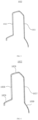
- the insert member 1022 is a hairpin coil. Before being inserted into the winding slots 1011, the insert member 1022 may include two linear sides. The two linear sides are inserted into the winding slots 1011 through the first end 1012, and the portions of the two linear sides accommodated in the winding slots 1011 form the first insert part 1026 and the second insert part 1027, respectively. With further reference to FIG. 4 , the portions of the two linear sides extending out through the second end 1013 form the first extending part 1029 and the second extending part 1030, respectively.
- the plurality of winding slots 1011 are arranged along the circumferential direction of the stator core 101, and two adjacent insert members 1022 may be directly connected or indirectly connected via other conductive structures.
- a conductive strip may be provided at the second end 1013 of the stator core 101, and two ends of the conductive strip are respectively welded to two adjacent insert members 1022 to connect the two adjacent insert members 1022.
- the insert member 1022 may be a full-pitch coil, and the span of the full-pitch coil equals to the pole pitch of the stator 10.
- the plurality of winding slots 1011 are uniformly arranged along the circumferential direction of the inner wall of the stator core 101. In other words, the plurality of winding slots 1011 are arranged equidistantly in the circumferential direction.
- the span of the insert member 1022 may be determined according to the number of slots, thereby reducing the line type of the insert member 1022 and simplifying the line insertion process.
- the winding slots 1011 extend along the axial direction of the stator core 101 and penetrate through the stator core 101 along the axial direction of the stator core 101. According to this embodiment, the bending of the insert member 1022 can be reduced during the insertion of the insert member 1022 into the winding slots 1011, and the difficulty in assembling can be reduced.
- the number of the winding slots 1011 is 12 ⁇ N, where N is a positive integer.
- the span of the first insert part 1026 and the second insert part 1027 is six winding slots 1011.
- the first insert part 1026 and the second insert part 1027 are each used as the conductor 1021 in the corresponding winding slot 1011.
- the conductors 1021 in each winding slot 1011 are arranged as a plurality of layers.
- the plurality of layers of conductors 1021 are sequentially distributed along a direction from the slot bottom of the winding slot 1011 to the slot opening of the winding slot 1011.
- the plurality of layers of conductors 1021 are stacked along the radial direction of the stator core 101.
- the first insert part 1026 and the second insert part 1027 of the insert member 1022 are two conductors 1021 of the insert member 1022.
- the conductor 1021 is an effective side of the insert member 1022 and is the portion that is embedded in the stator core 101 for electromagnetic pole energy conversion. Providing a plurality of layers of conductors 1021 can improve the energy conversion efficiency of the electromagnetic poles.
- the two conductors 1021 of the insert member 1022 are embedded in the two winding slots 1011, respectively.
- the plurality of layers of conductors 1021 in each winding slot 1011 belong to a plurality of insert members 1022, respectively.
- the slot opening of the winding slot 1011 is present on the inner wall of the stator core 101 facing the rotor.
- the slot bottom of the winding slot 1011 is the bottom wall of the winding slot 1011 opposite to the slot opening.
- the cross-section of the conductor 1021 may be any one or more of rectangular, oval, racetrack-like, etc.
- the above structure can improve the slot fill factor of the stator core 101.
- the stator winding 102 includes a plurality of phase windings.
- Each phase winding includes at least one branch, and each branch includes a plurality of insert members 1022 connected in series.
- the number of the phase windings may be 2, 3, 4, or 5. Of course, the number of the phase windings may also be greater than 5.
- the stator 10 of the embodiments of the present application is suitable for motors with different phase number and can adapt to different voltage and power ranges.
- the stator winding 102 may include three phase windings, that is, a first phase winding 1023, a second phase winding, and a third phase winding.
- the first phase winding 1023 is a U-phase winding
- the second phase winding is a V-phase winding
- the third phase winding is a W-phase winding.
- Each phase winding may include only one branch, or may include a plurality of branches.
- the branch of the phase winding may also be referred to as a parallel branch.
- the number of the branches of the phase winding may be any integer to expand the designed use range of the winding and adapt to different voltage and power ranges.
- the phase winding in the embodiments of the present application includes a first branch U1 and a second branch U2.
- both the first branch U1 and the second branch U2 may include a plurality of insert members 1022.
- the plurality of insert members 1022 of the first branch U1 are connected in series, and the plurality of insert members 1022 of the second branch U2 are connected in series.
- the number of the insert members 1022 of the branch is not limited in this embodiment.
- the number of the insert members 1022 of the branch can be freely adjusted as required to expand the designed use range of the winding and adapt to different voltage and power ranges.
- FIG. 6 is a schematic structural diagram of a phase winding of a stator provided according to some embodiments of the present application
- FIG. 7 is a schematic structural diagram of a first phase winding 1023 of a stator 10 provided according to some embodiments of the present application.
- the stator winding 102 includes a first phase winding 1023.
- the first phase winding 1023 includes a first branch and a second branch, and the first branch includes a first wire incoming end, a first wire outgoing end, and a plurality of conductors 1021 connected in series between the first wire incoming end and the first wire outgoing end.
- the second branch includes a second wire incoming end, a second wire outgoing end, and a plurality of conductors connected in series between the second wire incoming end and the second wire outgoing end.
- the first wire incoming end and the second wire incoming end are respectively connected to the conductors 1021 in different layers in the same winding slot 1011; the first wire outgoing end and the second wire outgoing end are respectively connected to the conductors 1020 in different layers in the same winding slot 1011.
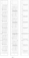
- FIG. 7 shows a U-phase winding.
- the stator winding of the present application will be described in detail below by taking a U-phase winding as an example.
- the U-phase winding includes a plurality of branches, two of which serve as a first branch U1 and a second branch U2.
- the first table shows the first branch U1
- the second table shows the second branch U2
- the third table shows the U-phase winding.
- One of the first wire incoming end and the first wire outgoing end is a positive electrode wiring end, and the other one is a negative electrode wiring end.
- the electric polarity of the second wire incoming end is the same as that of the first wire incoming end, and the electric polarity of the second wire outgoing end is the same as that of the first wire outgoing end.
- U1+ represents the first wire incoming end of the first branch U1
- U1- represents the first wire outgoing end of the first branch U1
- U2+ represents the second wire incoming end of the second branch U2
- U2- represents the second wire outgoing end of the second branch U2.
- N and S represent two magnetic poles of the stator.
- the stator is provided with eight magnetic poles, i.e., four magnetic pole pairs.
- the stator core is provided with a plurality of winding slots 1011, and the plurality of winding slots 1011 are represented by a row of numbers below the N-poles and S-poles.
- the stator core 101 is provided with 48 winding slots 1011.
- the 48 winding slots 1011 are represented by a row of numbers below the N-poles and S-poles, i.e., 1-48.
- each magnetic pole corresponds to six winding slots 1011.
- a plurality of layers of conductors 1021 are accommodated in each winding slot 1011. Illustratively, in FIG. 7 , eight conductors 1021 are accommodated in each winding slot 1011. The eight conductors 1021 are located on layers a, b, c, d, e, f, g, and h, respectively.
- the first branch U1 includes a plurality of conductors 1021 connected in series.
- the plurality of conductors of the first branch U1 are represented by serial numbers distributed throughout the table.
- the first branch U1 includes 64 conductors, and the 64 conductors are represented by 64 serial numbers distributed in the table; the 64 conductors of the first branch U1 are sequentially connected according to the serial numbers; the first wire incoming end is connected to the first conductor, and the first wire outgoing end is connected to the 64 th conductor.
- the second branch U2 includes a plurality of conductors connected in series.
- the plurality of conductors of the second branch U2 are represented by serial numbers distributed throughout the table.
- the second branch U2 includes 64 conductors, and the 64 conductors are represented by 64 serial numbers distributed in the table; the 64 conductors of the second branch U2 are sequentially connected according to the serial numbers; the second wire incoming end is connected to the first conductor, and the second wire outgoing end is connected to the 64 th conductor.
- the distance between the first wire incoming end and the second wire incoming end and the distance between the first wire outgoing end and the second wire outgoing end can be reduced, and the connection of two branches is facilitated, which is beneficial for the arrangement of the busbar and the implementation of the winding processing technology.
- the conductors in each winding slot 1011 are arranged as n layers, where n is a positive even number.
- the n layers of conductors are denoted as layer L 1 , ..., layer L i , ..., and layer L n , where 1 ⁇ i ⁇ n.
- the first wire incoming end and the second wire incoming end are respectively connected to the layer Li conductor and the layer L n conductor in the same winding slot 1011.
- the first wire outgoing end and the second wire outgoing end are respectively connected to the layer Li conductor and the layer L n conductor in the same winding slot 1011.
- both the first wire incoming end U1+ and the first wire outgoing end U1- are connected to a layer L 1 conductor, and the layer Li conductors are close to the outer end of the stator core 101 along the radial direction. This facilitates the connection of the first wire incoming end U1+ and the first wire outgoing end U1- to the external busbar.
- Both the second wire incoming end U2+ and the second wire outgoing end U2- are connected to a layer L n conductor, and the layer L n conductors are close to the inner end of the stator core along the radial direction. This facilitates the connection of the second wire incoming end and the second wire outgoing end to the external busbar.
- both the first branch U1 and the second branch U2 include a plurality of insert members 1022 connected in series, and each insert member 1022 includes at least one conductor.
- the insert member 1022 may be provided with one conductor or a plurality of conductors.
- the conductors are arranged in the winding slots 1011 and feature simple structure, convenient production, and small occupied space, and the above technical solution can improve the power density of the motor.
- At least two conductors connected to each other are in the same layer along a direction from the first wire incoming end to the first wire outgoing end.
- the conductors connected in the same layer can balance the slot potential of the branches and reduce the circulating current loss between the branches.
- the first branch includes 2k conductors; along a direction from the first wire incoming end to the second wire incoming end, the first branch includes 2k conductors, which are denoted as A 1 , A 2 , ..., A k , ..., A 2k-1 , and A 2k ; the A k th conductor and the A k+1 th conductor are both layer L n conductors; the A 1 th conductor to the A k th conductor are sequentially connected from the layer Li to the layer L n along a first wave winding direction, the A k+1 th conductor to the A 2k th conductor are sequentially connected from the layer L n to the layer Li along a second wave winding direction, and the first wave winding direction is opposite to the second wave winding direction.
- the k layers of conductors of the branch are connected in series; the conductors are sequentially connected from the layer A 1 to layer A k and then sequentially connected from the layer A k layer to layer A 2k .
- the layer A 1 is connected to the first wire incoming end, and the layer A 2k is connected to the first wire outgoing end.
- the second wire incoming end U2+ is connected to conductor No. 1 of the second branch U2, and the second wire outgoing end U2- is connected to conductor No. 64 of the second branch U2.
- conductors No. 1-32 of the second branch are connected in series sequentially.
- Conductors No. 1, 3, 5, and 7 are all layer-h conductors, and conductors No. 2, 4, 6, and 8 are all layer-g conductors.
- Conductors No. 9, 11, 13, and 15 are all layer-f conductors.
- Conductors No. 10, 12, 14, and 16 are all layer-e conductors.
- Conductors No. 17, 19, 21, and 23 are all layer-d conductors.
- Conductors No. 18, 20, 22, and 24 are all layer-c conductors.
- Conductors No. 25, 27, 29, and 31 are all layer-b conductors.
- Conductors No. 26, 28, 30, and 32 are all layer-a conductors.
- conductors No. 33-64 of the second branch are connected in series sequentially.
- Conductors No. 33, 35, 37, and 39 are all layer-a conductors
- conductors No. 34, 36, 38, and 40 are all layer-b conductors.
- Conductors No. 41, 43, 45, and 47 are all layer-c conductors.
- Conductors No. 42, 44, 46, and 48 are all layer-d conductors.
- Conductors No. 49, 51, 53, and 55 are all layer-e conductors.
- Conductors No. 50, 52, 54, and 56 are all layer-f conductors.
- Conductors No. 57, 59, 61, and 63 are all layer-g conductors.
- Conductors No. 58, 60, 62, and 64 are all layer-h conductors.
- the conductor connected to the first wire incoming end of the first branch U1 and the conductor 1021 connected to the second wire incoming end of the second branch U2 are provided in the same winding slot 1011.
- the wire incoming ends of two branches are led out from the same winding slot 1011, such that the distance between the wire incoming ends of the two branches is further reduced, and the connection of the wire incoming ends of the two branches is facilitated, which is beneficial for the arrangement of the busbar and the implementation of the winding processing technology.
- the conductors No. 32 and 33 of the second branch U2 are all layer-a conductors.
- the conductors connected in the same layer can also balance the slot potential of the branches and reduce the circulating current loss between the branches.
- the conductor No. 1 connected to the second wire incoming end U2+ is located in the No. 13 winding slot; the conductor No. 64 connected to the second wire outgoing end U2- is located in the No. 20 winding slot.
- the conductor No. 1 connected to the second wire incoming end U2+ and the conductor No. 64 connected to the second wire outgoing end U2- are all layer-a conductors. This embodiment is beneficial for the arrangement of the busbar and facilitates the connection of the first wire incoming end U1+ and the first wire outgoing end U1- to an external circuit.
- the stator 10 includes eight magnetic poles, and correspondingly, the phase winding includes eight pole phase groups. Sixteen insert members of the second branch U2 are distributed in the eight pole phase groups, such that the potential imbalance of the branch caused by the eccentricity of the rotor can be reduced.
- the span between the conductor connected to the first wire incoming end of the first branch U1 and the conductor connected to the second wire incoming end of the second branch U2 is less than or equal to the pole pitch.
- the distance between the wire incoming ends of the two branches can be reduced, and the connection of the wire incoming ends of the two branches is facilitated, which is beneficial for the arrangement of the busbar and the implementation of the winding processing technology.
- the plurality of branches of the phase winding may be connected in series or in parallel.
- the first branch U1 and the second branch U2 may be connected in series or in parallel.
- the conductor No. 1 of the first branch U1 is connected to the first wire incoming end U1+ of the first branch U1, and the conductor No. 1 of the second branch U2 is connected to the second wire outgoing end U2+ of the second branch U2.
- the conductor No. 1 of the first branch U1 and the conductor No. 1 of the second branch U2 are provided in the same winding slot, i.e., the No. 13 winding slot.
- the first wire incoming ends of two branches are led out from the same winding slot 1011, such that the distance between the wire incoming ends of the two branches is further reduced, and the connection of the wire incoming ends of the two branches is facilitated, which is beneficial for the arrangement of the busbar and the implementation of the winding processing technology.
- the conductor No. 1 of the first branch U1 and the conductor No. 64 of the first branch U1 are all layer-a conductors
- the conductor No. 1 of the second branch U2 and the conductor No. 64 of the second branch U1 are all layer-h conductors. This embodiment is beneficial for the arrangement of the busbar and facilitates the connection of the wire incoming ends (U1+, U2 +) and the wire outgoing ends (U1-, U2-) to an external circuit.
- the U-phase winding shown in FIG. 7 can balance the slot potential of each branch, reduce the circulating current loss between the branches, reduce the unbalance of electromotive force of the branches caused by the eccentricity of the rotor, and reduce the voltage stress of the conductors in the slots, and meanwhile is beneficial for the arrangement of the busbar and the implementation of the winding processing technology.
- the maximum voltage drop between adjacent conductors in the same winding slot can be reduced to 0.47 U ph (U ph is the phase voltage).
- U ph is the phase voltage.
- the voltage drop in the winding slot can be reduced by 51.5%.
- FIG. 9 is a schematic diagram of a phase winding of a stator provided according to some embodiments of the present application. Illustratively, FIG. 9 shows a U-phase winding.
- each winding slot six conductors are accommodated in each winding slot.
- the eight conductors are located on layers a, b, c, d, e, and f, respectively.
- U1+ represents the first wire incoming end of the first branch U1, and U1- represents the first wire outgoing end of the first branch U1; U2+ represents the second wire incoming end of the second branch U2, and U2- represents the second wire outgoing end of the second branch U2.
- N and S represent two magnetic poles of the stator.
- the stator is provided with eight magnetic poles, i.e., four magnetic pole pairs.
- the stator core is provided with 48 winding slots.
- the 48 winding slots are represented by a row of numbers below the N-poles and S-poles, i.e., 1-48. Each magnetic pole corresponds to six winding slots.
- the positive electrode wiring end is the first wire incoming end
- the negative electrode wiring end is the first wire outgoing end.
- U1+ represents the first wire incoming end
- U1- represents the first wire outgoing end.
- the first wire incoming end U1+ is connected to conductor No. 1, and the first wire outgoing end U1- is connected to conductor No. 48.
- conductors No. 1-24 of the first branch are connected in series sequentially.
- Conductors No. 1, 3, 5, and 7 are all layer-a conductors, and conductors No. 2, 4, 6, and 8 are all layer-b conductors.
- Conductors No. 9, 11, 13, and 15 are all layer-c conductors.
- Conductors No. 10, 12, 14, and 16 are all layer-d conductors.
- Conductors No. 17, 19, 21, and 23 are all layer-e conductors.
- Conductors No. 18, 20, 22, and 24 are all layer-f conductors.
- the conductors No. 24 and 25 of the first branch U1 are all layer-f conductors.
- the two insert members 1022 can be welded at a regular interval without cross-layer welding, thereby simplifying the welding process.
- the conductors connected in the same layer can also balance the slot potential of the branches and reduce the circulating current loss between the branches.
- the conductor No. 1 connected to the first wire incoming end U1+ is located in the No. 13 winding slot; the conductor No. 48 connected to the first wire outgoing end U1- is located in the No. 20 winding slot.
- the conductor No. 1 connected to the first wire incoming end U1+ and the conductor No. 48 connected to the first wire outgoing end U1- are all layer-a conductors. This embodiment is beneficial for the arrangement of the busbar and facilitates the connection of the first wire incoming end U1+ and the first wire outgoing end U1- to an external circuit.
- the stator includes eight magnetic poles, and correspondingly, the phase winding includes eight pole phase groups.
- the plurality of insert members 1022 of the branch U1 are distributed in the eight pole phase groups, such that the potential imbalance of the branch caused by the eccentricity of the rotor can be reduced.
- the positive electrode wiring end is the second wire incoming end
- the negative electrode wiring end is the second wire outgoing end.
- U2+ represents the second wire incoming end
- U2- represents the second wire outgoing end.
- the second wire incoming end U2+ is connected to conductor No. 1, and the second wire outgoing end U2- is connected to conductor No. 48.
- conductors No. 25-48 of the second branch are connected in series sequentially.
- Conductors No. 25, 27, 29, and 31 are all layer-h conductors.
- Conductors No. 26, 28, 30, and 32 are all layer-e conductors.
- Conductors No. 33, 35, 37, and 39 are all layer-d conductors.
- Conductors No. 34, 36, 38, and 40 are all layer-c conductors.
- Conductors No. 41, 43, 45, and 47 are all layer-b conductors.
- Conductors No. 42, 44, 46, and 48 are all layer-a conductors.
- the wire incoming ends of two branches are led out from the same winding slot 1011, such that the distance between the wire incoming ends of the two branches is further reduced, and the connection of the wire incoming ends of the two branches is facilitated, which is beneficial for the arrangement of the busbar and the implementation of the winding processing technology.
- the embodiments of the present application are suitable for windings with different layers and are beneficial for widening the voltage range and the power range of the windings.
- FIG. 10 is a schematic diagram of three phase windings of a stator provided according to some embodiments of the present application.
- FIG. 10 shows the U-phase winding, the V-phase winding, and the W-phase winding of the stator winding.
- the three-phase windings of the stator winding are split and respectively shown in three tables.
- all the wire incoming ends in the plurality of phase windings are connected to conductors in different winding slots.
- the distance between the wire incoming ends can be increased to reduce the voltage stress among phases.
- all the wire outgoing ends in the plurality of phase windings are connected to conductors in different winding slots.
- the distance between the wire outgoing ends can be increased to reduce the voltage stress among phases.
- all the wire incoming ends and all the wire outgoing ends are connected to conductors in different winding slots.
- the distance between the wire incoming ends and the distance between the wire outgoing ends can be increased to reduce the voltage stress among phases.
- the U-phase winding includes a first branch U1 and a second branch U2.
- U1+ represents the first wire incoming end of the first branch U1, and U1- represents the first wire outgoing end of the first branch U1;
- U2+ represents the second wire incoming end of the second branch U2, and
- U2- represents the second wire outgoing end of the second branch U2.
- the U-phase winding of FIG. 10 may be obtained by combining the first branch U1 and the second branch U2 shown in FIG. 11 .
- the V-phase winding includes a first branch V1 and a second branch V2.
- V1+ represents the first wire incoming end of the first branch V1, and V1- represents the first wire outgoing end of the first branch V1;
- V2+ represents the second wire incoming end of the second branch V2, and
- V2- represents the second wire outgoing end of the second branch V2.
- the W-phase winding includes a first branch W1 and a second branch W2.
- W1+ represents the first wire incoming end of the first branch W1, and W1- represents the first wire outgoing end of the first branch W1;
- W2+ represents the second wire incoming end of the second branch W2, and
- W2- represents the second wire outgoing end of the second branch W2.
- the 12 conductors connected to the wiring ends U1+, U1-, U2+, U2-, V1+, V1-, V2+, V2-, W1+, W1-, W2+, and W2- are respectively provided in 12 winding slots.
- the six conductors connected to the wiring ends U1+, U1-, U2+, U2-, V1+, and V1- are all layer-a conductors.
- the above wiring ends are all close to the outer end of the stator core along the radial direction, which can facilitate the welding.
- the 12 conductors connected to the wiring ends U1+, U1-, U2+, U2-, V1+, V1-, V2+, V2-, W1+, W1-, W2+, and W2- are distributed in adjacent three magnetic poles, which is beneficial for the arrangement of the busbar.
- the U-phase winding includes a first branch U1 and a second branch U2 connected in series.
- the V-phase winding includes a first branch V1 and a second branch V2 connected in series.
- the W-phase winding includes a first branch W1 and a second branch W2 connected in series.
- 12 ⁇ N winding slots 1011 are present in the inner wall of the stator core 101, where N is a positive integer.
- the conductors of the first phase winding are distributed in 4 ⁇ N winding slots.
- the second phase winding is distributed in 4 ⁇ N winding slots, and the third phase winding is distributed in 4 ⁇ N winding slots.
- the stator winding includes three phase windings, i.e., a U-phase winding, a V-phase winding, and a W-phase winding.
- N 4
- the U-phase winding, the V-phase winding, and the W-phase winding are each distributed in 16 winding slots 1011.
- the U-phase winding is distributed in No. 1-2, No. 7-8, No. 13-14, No. 19-20, No. 25-26, No. 31-32, No. 37-38, and No. 43-44 slots.
- the V-phase winding is distributed in No. 5-6, No. 11-12, No. 17-18, No. 23-24, No. 29-30, No. 35-36, No. 41-42, and No. 47-48 slots.
- the W-phase winding is distributed in No. 3-4, No. 9-10, No. 15-16, No. 21-22, No. 27-28, No. 33-34, No. 39-40, and No. 45-46 slots.
- the above arrangement mode can reduce the circulating current loss among the three phase windings and improve the conversion efficiency of the motor.
- the U-phase winding includes a first branch U1 and a second branch U2 connected in series.
- the V-phase winding includes a first branch V1 and a second branch V2 connected in series.
- the W-phase winding includes a first branch W1 and a second branch W2 connected in series.
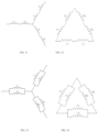
- FIG. 13 is a schematic connection diagram of phase windings of a stator winding of a stator provided according to some other embodiments of the present application.
- the stator winding includes three phase windings, i.e., a U-phase winding, a V-phase winding, and a W-phase winding.
- the three phase windings are connected as a triangle.
- the U-phase winding includes a first branch U1 and a second branch U2 connected in parallel.
- the V-phase winding includes a first branch V1 and a second branch V2 connected in parallel.
- the W-phase winding includes a first branch W1 and a second branch W2 connected in parallel.
- FIG. 14 is a schematic connection diagram of phase windings of a stator winding of a stator provided according to still some embodiments of the present application.
- the stator winding includes three phase windings, i.e., a U-phase winding, a V-phase winding, and a W-phase winding.
- the three phase windings are connected as a star.
- the U-phase winding includes a first branch U1 and a second branch U2 connected in parallel.
- the V-phase winding includes a first branch V1 and a second branch V2 connected in parallel.
- the W-phase winding includes a first branch W1 and a second branch W2 connected in parallel.
- the number of serial turns per phase of the stator winding can be adjusted to adapt to application scenarios involving different voltage and power ranges.
- the embodiments of the present application further provide a motor, which includes the stator provided by any one of the aforementioned embodiments.
- the motor further includes a rotor, and the rotor is provided in a space formed by the enclosing of the inner wall of the stator core.
- the motor of the embodiments of the present application may be a generator or an electromotor.
- the embodiments of the present application further provide an electric device, which includes the motor provided by any one of the aforementioned embodiments.
- the electric device includes a powertrain, which includes a reducer and the motor described above.
- the motor is in transmission connection to the reducer.
- the drive shaft of the motor and the input shaft of the reducer can be in transmission connection through a transmission member such as a coupling, such that the driving force is output from the motor to the reducer.
- the embodiments of the present application further provide a vehicle, which includes the powertrain described above.
- the powertrain described above is provided in the vehicle and provides operation power for the vehicle.
- the vehicle may be specifically, e.g., a new energy vehicle that is driven by electric energy.
- the new energy vehicle may be a hybrid electric vehicle, a pure electric vehicle, a fuel cell electric vehicle, or the like, or may be a vehicle using a high-efficiency energy storage device such as a super capacitor, a flywheel battery, or a flywheel energy storage device as the source of electric energy.
Landscapes
- Engineering & Computer Science (AREA)
- Power Engineering (AREA)
- Windings For Motors And Generators (AREA)
Applications Claiming Priority (1)
| Application Number | Priority Date | Filing Date | Title |
|---|---|---|---|
| PCT/CN2022/121109 WO2024060257A1 (zh) | 2022-09-23 | 2022-09-23 | 用电装置、电机及其定子 |
Publications (2)
| Publication Number | Publication Date |
|---|---|
| EP4580002A1 true EP4580002A1 (de) | 2025-07-02 |
| EP4580002A4 EP4580002A4 (de) | 2025-10-22 |
Family
ID=90453796
Family Applications (1)
| Application Number | Title | Priority Date | Filing Date |
|---|---|---|---|
| EP22959259.7A Pending EP4580002A4 (de) | 2022-09-23 | 2022-09-23 | Elektrische vorrichtung sowie motor und stator dafür |
Country Status (5)
| Country | Link |
|---|---|
| US (1) | US20250219490A1 (de) |
| EP (1) | EP4580002A4 (de) |
| JP (1) | JP2025528544A (de) |
| CN (1) | CN117916980A (de) |
| WO (1) | WO2024060257A1 (de) |
Families Citing this family (1)
| Publication number | Priority date | Publication date | Assignee | Title |
|---|---|---|---|---|
| JP7852085B2 (ja) | 2022-09-20 | 2026-04-27 | 寧徳時代(上海)智能科技有限公司 | モータ及びその固定子と電力消費装置 |
Family Cites Families (9)
| Publication number | Priority date | Publication date | Assignee | Title |
|---|---|---|---|---|
| JP3741081B2 (ja) * | 2002-06-12 | 2006-02-01 | 株式会社デンソー | 回転電機のセグメント順次接合型ステータコイル |
| US9379586B2 (en) * | 2013-04-24 | 2016-06-28 | GM Global Technology Operations LLC | Bar wound stator winding layout with long-pitched and short-pitched coils |
| DE102019135426A1 (de) * | 2019-12-20 | 2021-06-24 | Valeo Siemens Eautomotive Germany Gmbh | Stator mit versetzen Pins für eine elektrische Maschine |
| CN111725931B (zh) * | 2020-06-28 | 2026-02-03 | 苏州汇川联合动力系统股份有限公司 | 扁线定子组件及驱动电机 |
| CN114204708B (zh) * | 2021-10-30 | 2023-04-07 | 华为数字能源技术有限公司 | 定子、扁线电机、动力总成和车辆 |
| CN114583863B (zh) * | 2021-12-31 | 2024-05-10 | 华为数字能源技术有限公司 | 定子、扁线电机、动力总成和车辆 |
| CN114552811B (zh) * | 2022-03-29 | 2024-03-01 | 浙江极氪智能科技有限公司 | 一种电机定子及其应用的电机 |
| CN114825723B (zh) * | 2022-04-22 | 2025-08-19 | 浙江极氪智能科技有限公司 | 一种多层扁线绕组、定子组件及电机 |
| CN115001182B (zh) * | 2022-06-30 | 2025-07-18 | 重庆青山工业有限责任公司 | 一种电机的双层扁线绕组结构 |
-
2022
- 2022-09-23 EP EP22959259.7A patent/EP4580002A4/de active Pending
- 2022-09-23 CN CN202280005830.6A patent/CN117916980A/zh active Pending
- 2022-09-23 WO PCT/CN2022/121109 patent/WO2024060257A1/zh not_active Ceased
- 2022-09-23 JP JP2025514205A patent/JP2025528544A/ja active Pending
-
2025
- 2025-03-21 US US19/086,924 patent/US20250219490A1/en active Pending
Also Published As
| Publication number | Publication date |
|---|---|
| US20250219490A1 (en) | 2025-07-03 |
| JP2025528544A (ja) | 2025-08-28 |
| CN117916980A (zh) | 2024-04-19 |
| EP4580002A4 (de) | 2025-10-22 |
| WO2024060257A1 (zh) | 2024-03-28 |
Similar Documents
| Publication | Publication Date | Title |
|---|---|---|
| EP4175125A1 (de) | Stator, flachdrahtmotor, antriebsstrang und fahrzeug | |
| EP4135165B1 (de) | Motorstator, motor und fahrzeug | |
| CN114583863B (zh) | 定子、扁线电机、动力总成和车辆 | |
| CN113422453B (zh) | 一种六相扁线波绕组结构、六相电机、动力总成和车辆 | |
| CN105356641B (zh) | 旋转电机和具备该旋转电机的车辆 | |
| CN218920099U (zh) | 定子、扁线电机、动力总成和车辆 | |
| EP4407844A1 (de) | Flachdraht-elektromotor und stator dafür | |
| US12301083B2 (en) | Motor, and stator and electric device thereof | |
| CN221842388U (zh) | 车辆、动力总成、扁线电机及其定子 | |
| US20250219490A1 (en) | Electrical device, and motor and stator thereof | |
| WO2024007709A1 (zh) | 定子、扁线电机、动力总成及车辆 | |
| JP3251626U (ja) | ステータ、フラットワイヤーモータ、パワートレーン及び車両 | |
| CN112311177A (zh) | 一种电机及包括该电机的设备 | |
| CN110337772A (zh) | 分段定子电机 | |
| EP4404437A1 (de) | Motor, antriebsstrang und fahrzeug | |
| CN215897556U (zh) | 一种电机、自动化或半自动化设备和发电设备 | |
| CN222484410U (zh) | 定子绕组、定子总成和电机 | |
| CN218850596U (zh) | 二十七槽永磁电机 | |
| CN216216162U (zh) | 一种电机定子及具有其的电机 | |
| CN121791517A (zh) | 一种分布式集中绕组在多模块驱动模块的应用 | |
| CN119401704A (zh) | 线圈绕组接线结构、接下线方法及三相电动机 | |
| CN117477810A (zh) | 径向磁场单相交流永磁无刷电机 | |
| CN111835103A (zh) | 旋转电机 | |
| CN111478475A (zh) | 一种电机定子及电机 | |
| CN110875644A (zh) | 内转子多相电机 |
Legal Events
| Date | Code | Title | Description |
|---|---|---|---|
| STAA | Information on the status of an ep patent application or granted ep patent |
Free format text: STATUS: THE INTERNATIONAL PUBLICATION HAS BEEN MADE |
|
| PUAI | Public reference made under article 153(3) epc to a published international application that has entered the european phase |
Free format text: ORIGINAL CODE: 0009012 |
|
| STAA | Information on the status of an ep patent application or granted ep patent |
Free format text: STATUS: REQUEST FOR EXAMINATION WAS MADE |
|
| 17P | Request for examination filed |
Effective date: 20250327 |
|
| AK | Designated contracting states |
Kind code of ref document: A1 Designated state(s): AL AT BE BG CH CY CZ DE DK EE ES FI FR GB GR HR HU IE IS IT LI LT LU LV MC MK MT NL NO PL PT RO RS SE SI SK SM TR |
|
| REG | Reference to a national code |
Ref country code: DE Ref legal event code: R079 Free format text: PREVIOUS MAIN CLASS: H02K0001160000 Ipc: H02K0003280000 |
|
| A4 | Supplementary search report drawn up and despatched |
Effective date: 20250919 |
|
| RIC1 | Information provided on ipc code assigned before grant |
Ipc: H02K 3/28 20060101AFI20250915BHEP Ipc: H02K 3/12 20060101ALI20250915BHEP |
|
| DAV | Request for validation of the european patent (deleted) | ||
| DAX | Request for extension of the european patent (deleted) |