EP4404437A1 - Motor, antriebsstrang und fahrzeug - Google Patents
Motor, antriebsstrang und fahrzeug Download PDFInfo
- Publication number
- EP4404437A1 EP4404437A1 EP24152658.1A EP24152658A EP4404437A1 EP 4404437 A1 EP4404437 A1 EP 4404437A1 EP 24152658 A EP24152658 A EP 24152658A EP 4404437 A1 EP4404437 A1 EP 4404437A1
- Authority
- EP
- European Patent Office
- Prior art keywords
- stator
- wire
- layer flat
- flat
- phase
- Prior art date
- Legal status (The legal status is an assumption and is not a legal conclusion. Google has not performed a legal analysis and makes no representation as to the accuracy of the status listed.)
- Pending
Links
- 239000004020 conductor Substances 0.000 claims abstract description 475
- 238000004804 winding Methods 0.000 claims abstract description 256
- XEEYBQQBJWHFJM-UHFFFAOYSA-N Iron Chemical group [Fe] XEEYBQQBJWHFJM-UHFFFAOYSA-N 0.000 claims abstract description 100
- 230000005540 biological transmission Effects 0.000 claims description 5
- 239000010410 layer Substances 0.000 description 456
- 238000010586 diagram Methods 0.000 description 22
- 230000000052 comparative effect Effects 0.000 description 19
- 238000003466 welding Methods 0.000 description 11
- 230000000875 corresponding effect Effects 0.000 description 5
- 230000027311 M phase Effects 0.000 description 3
- 238000009826 distribution Methods 0.000 description 3
- RYGMFSIKBFXOCR-UHFFFAOYSA-N Copper Chemical compound [Cu] RYGMFSIKBFXOCR-UHFFFAOYSA-N 0.000 description 2
- 238000004364 calculation method Methods 0.000 description 2
- 229910052802 copper Inorganic materials 0.000 description 2
- 239000010949 copper Substances 0.000 description 2
- 238000004146 energy storage Methods 0.000 description 2
- 238000004519 manufacturing process Methods 0.000 description 2
- 230000001360 synchronised effect Effects 0.000 description 2
- 238000006243 chemical reaction Methods 0.000 description 1
- 238000007796 conventional method Methods 0.000 description 1
- 230000008878 coupling Effects 0.000 description 1
- 238000010168 coupling process Methods 0.000 description 1
- 238000005859 coupling reaction Methods 0.000 description 1
- 230000000593 degrading effect Effects 0.000 description 1
- 230000000694 effects Effects 0.000 description 1
- 239000000446 fuel Substances 0.000 description 1
- 230000014509 gene expression Effects 0.000 description 1
- 230000017525 heat dissipation Effects 0.000 description 1
- 238000000034 method Methods 0.000 description 1
- 230000007935 neutral effect Effects 0.000 description 1
- 238000004088 simulation Methods 0.000 description 1
- 239000002356 single layer Substances 0.000 description 1
- 239000007787 solid Substances 0.000 description 1
Images


Classifications
-
- H—ELECTRICITY
- H02—GENERATION; CONVERSION OR DISTRIBUTION OF ELECTRIC POWER
- H02K—DYNAMO-ELECTRIC MACHINES
- H02K3/00—Details of windings
- H02K3/04—Windings characterised by the conductor shape, form or construction, e.g. with bar conductors
- H02K3/28—Layout of windings or of connections between windings
-
- H—ELECTRICITY
- H02—GENERATION; CONVERSION OR DISTRIBUTION OF ELECTRIC POWER
- H02K—DYNAMO-ELECTRIC MACHINES
- H02K1/00—Details of the magnetic circuit
- H02K1/06—Details of the magnetic circuit characterised by the shape, form or construction
- H02K1/12—Stationary parts of the magnetic circuit
- H02K1/16—Stator cores with slots for windings
- H02K1/165—Shape, form or location of the slots
-
- H—ELECTRICITY
- H02—GENERATION; CONVERSION OR DISTRIBUTION OF ELECTRIC POWER
- H02K—DYNAMO-ELECTRIC MACHINES
- H02K3/00—Details of windings
- H02K3/04—Windings characterised by the conductor shape, form or construction, e.g. with bar conductors
- H02K3/12—Windings characterised by the conductor shape, form or construction, e.g. with bar conductors arranged in slots
-
- H—ELECTRICITY
- H02—GENERATION; CONVERSION OR DISTRIBUTION OF ELECTRIC POWER
- H02K—DYNAMO-ELECTRIC MACHINES
- H02K2213/00—Specific aspects, not otherwise provided for and not covered by codes H02K2201/00 - H02K2211/00
- H02K2213/03—Machines characterised by numerical values, ranges, mathematical expressions or similar information
Definitions
- This application relates to the field of motors, and specifically, to a motor, a powertrain, and a vehicle.
- the flat-wire motor has a high copper fill ratio, facilitates heat dissipation for a motor winding, can improve a voltage withstand capability of the winding and reduce a length of an end of the winding, and has other advantages, and this can further improve torque density and power density of a motor. Therefore, the flat-wire motor becomes an important measure to promote lightweight of a vehicle, increase an endurance mileage of an electric vehicle, improve space utilization of a vehicle, and reduce costs of a powertrain.
- a winding mode for a stator winding of a conventional flat-wire motor is usually a full-pitch winding.
- the motor includes a stator iron core, stator slots are provided along a circumferential direction of the stator iron core, and the stator winding is wound on the stator iron core through the stator slots.
- the flat-wire motor with the full-pitch structure has a high harmonic winding coefficient, and has large torque fluctuation during operation. This increases noise vibration harshness (noise vibration harshness, NVH) of the motor and degrades performance of the motor.
- the stator winding may be disposed as a short-pitch winding to reduce the harmonic winding coefficient of the flat-wire motor, and improve NVH performance of an electric vehicle.
- the short-pitch disposing manner is limited by a winding form, a connection for a stator winding in which a quantity N/2 of layers of flat-wire conductors is an odd number cannot be implemented, and it is difficult to well weaken a harmonic magnetic field.
- This application provides a motor, a powertrain, and a vehicle, to implement a connection for a stator winding in which a quantity N of layers of flat-wire conductors is an odd number or N/2 is an odd number, and to weaken a harmonic magnetic field.
- this application provides a motor.
- the motor includes a stator and a rotor.
- the stator includes a stator iron core and a stator winding.
- 54 stator slots are evenly provided along a circumferential direction of an inner wall of the stator iron core.
- Each stator slot includes six layers of flat-wire conductors, and a first-layer flat-wire conductor to a sixth-layer flat-wire conductor are sequentially arranged in the stator slot along a radial direction of the stator iron core.
- the first-layer flat-wire conductor is close to the bottom of the stator slot along the radial direction of the stator iron core.
- stator slots Every two first-layer flat-wire conductors are connected to each other, and two stator slots, in which two first-layer flat-wire conductors connected to each other are respectively located, are spaced apart by nine stator slots or six stator slots.
- Second-layer flat-wire conductors are respectively connected to third-layer flat-wire conductors, and two stator slots, in which a second-layer flat-wire conductor and a third-layer flat-wire conductor that are connected to each other are located, are spaced apart by seven stator slots.
- Fourth-layer flat-wire conductors are respectively connected to fifth-layer flat-wire conductors, and two stator slots, in which a fourth-layer flat-wire conductor and a fifth-layer flat-wire conductor that are connected to each other are located, are spaced apart by seven stator slots. Every two sixth-layer flat-wire conductors are connected to each other, and two stator slots, in which two sixth-layer flat-wire conductors connected to each other are respectively located, are spaced apart by eight stator slots.
- each stator slot is provided with six layers of flat-wire conductors.
- the first-layer flat-wire conductor and the sixth-layer flat-wire conductor each may be formed through plug-in of hairpin coils at a same layer.
- a plug-in mode is simple, without cross-layer plug-in.
- First-layer flat-wire conductors are connected at a same layer, and first-layer flat-wire conductors connected to each other may be spaced apart by nine stator slots or six stator slots. Therefore, the first-layer flat-wire conductor may include hairpin coils with two types of spans.
- the sixth-layer flat-wire conductor is at a separate layer, every two sixth-layer flat-wire conductors may be connected to each other, and two sixth-layer flat-wire conductors connected to each other may be spaced apart by eight stator slots. Therefore, the sixth-layer flat-wire conductor may include hairpin coils with one type of span. From the second-layer flat-wire conductor to the fifth-layer flat-wire conductor, every two adjacent layers of flat-wire conductors may be connected to each other, and two flat-wire conductors connected to each other may be spaced apart by seven stator slots, to implement a short-pitch connection.
- a connection mode for the flat-wire conductors may remain unchanged, and a connection structure of the stator winding is simple.
- the flat-wire conductors in the stator winding in this application are connected at a same layer or adjacent layers during connection, without a cross-layer connection.
- a type of a connection wire is simple, and automatic plug-in can be implemented.
- testing shows that a flat-wire motor with this structure can further effectively weaken a harmonic magnetic field, for example, effectively weaken (6kp)th-order noise in a conventional short-pitch winding, to improve NVH performance of a motor.
- a flat-wire motor with the foregoing performance may be used in an electric vehicle to effectively reduce noise during operation of the electric vehicle.
- each phase of winding of the stator winding includes a plurality of phase units that are evenly disposed along a circumferential direction of the stator iron core at spacings, from the first-layer flat-wire conductor to the sixth-layer flat-wire conductor, every two layers of flat-wire conductors in each phase unit constitute a phase spread, and adjacent phase spreads of any phase unit are sequentially staggered by one stator slot.
- each phase of winding of the stator winding includes three parallel branches, one of a wire incoming end and a wire outgoing end of each parallel branch of each phase of winding is led out from the first-layer flat-wire conductor, and the other of the wire incoming end and the wire outgoing end of each parallel branch of each phase of winding is led out from the second-layer flat-wire conductor.
- each phase of winding of the stator winding includes three parallel branches, wire incoming ends of parallel branches of each phase of winding are located in adjacent stator slots, and wire outgoing ends of parallel branches of each phase of winding are located in adjacent stator slots.
- the motor includes a stator and a rotor.
- the stator includes a stator iron core and a stator winding.
- 72 stator slots are evenly provided along a circumferential direction of an inner wall of the stator iron core.
- Each stator slot includes eight layers of flat-wire conductors, and a first-layer flat-wire conductor to an eighth-layer flat-wire conductor are sequentially arranged in the stator slot along a radial direction of the stator iron core.
- the first-layer flat-wire conductor is close to the bottom of the stator slot along the radial direction of the stator iron core.
- stator slots are spaced apart by 12 stator slots or eight stator slots.
- Second-layer flat-wire conductors are respectively connected to third-layer flat-wire conductors, and two stator slots, in which a second-layer flat-wire conductor and a third-layer flat-wire conductor that are connected to each other are located, are spaced apart by 10 stator slots.
- Fourth-layer flat-wire conductors are respectively connected to fifth-layer flat-wire conductors, and two stator slots, in which a fourth-layer flat-wire conductor and a fifth-layer flat-wire conductor that are connected to each other are located, are spaced apart by 10 stator slots.
- Sixth-layer flat-wire conductors are respectively connected to seventh-layer flat-wire conductors, and two stator slots, in which a sixth-layer flat-wire conductor and a seventh-layer flat-wire conductor that are connected to each other are located, are spaced apart by 10 stator slots.
- each phase of winding of the stator winding includes a plurality of phase units that are evenly disposed along a circumferential direction of the stator iron core at spacings, from the first-layer flat-wire conductor to the eighth-layer flat-wire conductor, every two layers of flat-wire conductors in each phase unit constitute a phase spread, and adjacent phase spreads of any phase unit are sequentially staggered by one stator slot.
- each phase of winding of the stator winding includes four parallel branches, one of a wire incoming end and a wire outgoing end of each parallel branch of each phase of winding is led out from the first-layer flat-wire conductor, and the other of the wire incoming end and the wire outgoing end of each parallel branch of each phase of winding is led out from the second-layer flat-wire conductor.
- each phase of winding of the stator winding includes four parallel branches, wire incoming ends of parallel branches of each phase of winding are located in adjacent stator slots, and wire outgoing ends of parallel branches of each phase of winding are located in adjacent stator slots.
- the motor includes a stator and a rotor.
- the stator includes a stator iron core and a stator winding.
- 48 stator slots are evenly provided along a circumferential direction of an inner wall of the stator iron core.
- Each stator slot includes four layers of flat-wire conductors, and a first-layer flat-wire conductor to a fourth-layer flat-wire conductor are sequentially arranged in the stator slot along a radial direction of the stator iron core.
- the first-layer flat-wire conductor is close to the bottom of the stator slot along the radial direction of the stator iron core.
- Second-layer flat-wire conductors are respectively connected to third-layer flat-wire conductors, and two stator slots, in which a second-layer flat-wire conductor and a third-layer flat-wire conductor that are connected to each other are located, are spaced apart by four stator slots.
- each phase of winding of the stator winding includes a plurality of phase units that are evenly disposed along a circumferential direction of the stator iron core at spacings, from the first-layer flat-wire conductor to the fourth-layer flat-wire conductor, every two layers of flat-wire conductors in each phase unit constitute a phase spread, and adjacent phase spreads of any phase unit are sequentially staggered by one stator slot.
- each phase of winding of the stator winding includes two parallel branches, one of a wire incoming end and a wire outgoing end of each parallel branch of each phase of winding is led out from the first-layer flat-wire conductor, and the other of the wire incoming end and the wire outgoing end of each parallel branch of each phase of winding is led out from the second-layer flat-wire conductor.
- each phase of winding of the stator winding includes two parallel branches, wire incoming ends of parallel branches of each phase of winding are located in adjacent stator slots, and wire outgoing ends of parallel branches of each phase of winding are located in adjacent stator slots.
- this application further provides a motor.
- the motor includes a stator and a rotor.
- the stator includes a stator iron core and a stator winding.
- Z stator slots are evenly provided along a circumferential direction of an inner wall of the stator iron core.
- Each stator slot includes N layers of flat-wire conductors, and a first-layer flat-wire conductor to an Nth-layer flat-wire conductor are sequentially arranged in the stator slot along a radial direction of the stator iron core.
- the first-layer flat-wire conductor is close to the bottom of the stator slot along the radial direction of the stator iron core.
- the first-layer flat-wire conductor includes a plurality of hairpin coils with spans of Z/2p+1 and Z/2p-q+1, and any one of the hairpin coils is located at a same layer.
- the Nth-layer flat-wire conductor includes a plurality of hairpin coils with a span of Z/2p, and any one of the hairpin coils is located at a same layer. From a second-layer flat-wire conductor to an (N-1)th-layer flat-wire conductor, every two adjacent layers of flat-wire conductors include a plurality of hairpin coils with a span of Z/2p-1, and any one of the hairpin coils is located at two adjacent layers.
- q is a quantity of slots per phase per pole of the stator winding.
- 2p is a quantity of magnetic poles of the stator winding
- p is a positive integer.
- the first-layer flat-wire conductor and the Nth-layer flat-wire conductor each may be formed through plug-in of hairpin coils at a same layer.
- a plug-in mode is simple, without cross-layer plug-in.
- the first-layer flat-wire conductor is a separate coil group, and the coil group includes hairpin coils with two types of spans.
- the Nth-layer flat-wire conductor is at a separate layer, and hairpin coils with one type of span may form a separate coil group. Hairpin coils with a span of Z/2p-1 in every two adjacent layers of flat-wire conductors of a second-layer flat-wire conductor to an (N-1)th-layer flat-wire conductor may constitute a coil group.
- stator winding in this application includes a coil group corresponding to a single layer of flat-wire conductor and a coil group corresponding to two adjacent layers of flat-wire conductors.
- a plug-in structure of the coil groups is simple, without cross-layer plug-in. Any coil group includes a single type of coil, so that an automatic plug-in process can be implemented.
- a flat-wire motor with this structure can further effectively weaken a harmonic magnetic field, for example, effectively weaken (6kp)th-order noise in a conventional short-pitch winding, to improve NVH performance of a motor.
- a flat-wire motor with the foregoing performance may be used in an electric vehicle to effectively reduce noise during operation of the electric vehicle.
- each phase of winding of the stator winding includes a plurality of phase units that are evenly disposed along a circumferential direction of the stator iron core at spacings, from the first-layer flat-wire conductor to the Nth-layer flat-wire conductor, every two layers of flat-wire conductors in each phase unit constitute a phase spread, and adjacent phase spreads of any phase unit are sequentially staggered by one stator slot.
- the stator winding may include m phases of windings, each phase of winding includes a plurality of phase units, any phase unit includes at least two phase spreads, and adjacent phase spreads are staggered by one stator slot. In this way, a short-pitch winding can be formed.
- each phase of winding includes q or 2q parallel branches.
- a value of a quantity N of layers of flat-wire conductors ranges from 2 to 2q, and a quantity q of slots per phase per pole is less than or equal to 4.
- a quantity of types of hairpin coils forming the stator winding is N/2+2. Therefore, the stator winding may be formed by using a minimum quantity of types of hairpin coils.
- one of a wire incoming end and a wire outgoing end of each parallel branch of each phase of winding is led out from the first-layer flat-wire conductor, and the other of the wire incoming end and the wire outgoing end of each parallel branch of each phase of winding is led out from the second-layer flat-wire conductor.
- the wire incoming end and the wire outgoing end of each parallel branch each are led out from a bottom-layer flat-wire conductor of a stator slot. This can simplify a connection mode for wire entry and exit, and avoid cross-layer connection wires.
- wire incoming ends of parallel branches of each phase of winding are located in adjacent stator slots, and wire outgoing ends of parallel branches of each phase of winding are located in adjacent stator slots.
- Incoming wires of parallel branches of each phase of winding are led out from adjacent stator slots, and outgoing wires of the parallel branches are also led out from adjacent stator slots, so that the parallel branches can be conveniently connected to a busbar, to implement a parallel connection between the parallel branches. This simplifies a connection structure of the busbar, and avoids disposing a cross-layer or cross-slot neutral connection wire on the busbar.
- a quantity Z of stator slots is 48, 54, or 72, and N may be 4, 6, 8, 10, or 12.
- Z is 54, p is 3, and q is 3, a span of the first-layer flat-wire conductor is a combination of 10 and 7, a span of the Nth-layer flat-wire conductor is 9, and a span of every two adjacent layers of flat-wire conductors of the second-layer flat-wire conductor to the (N-1)th-layer flat-wire conductor is 8.
- Z is 72, p is 3, q is 3, a span of the first-layer flat-wire conductor is a combination of 10 and 7, a span of the Nth-layer flat-wire conductor is 9, and a span of every two adjacent layers of flat-wire conductors from the second-layer flat-wire conductor to the (N-1)th-layer flat-wire conductor is 8.
- Z is 48
- p is 4
- q is 2
- a span of the first-layer flat-wire conductor is a combination of 7 and 5
- a span of the Nth-layer flat-wire conductor is 6
- a span of every two adjacent layers of flat-wire conductors from the second-layer flat-wire conductor to the (N-1)th-layer flat-wire conductor is 5.
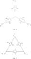
- pigtails of all phases of windings are connected in a Y shape or a triangular shape.
- the motor in this application includes but is not limited to a permanent magnet synchronous motor, an electrically excited synchronous motor, an asynchronous motor, and the like.
- the rotor of the flat-wire motor may have any rotor topology, for example, a surface-mounted type, a built-in "linear" shape, a built-in V shape, a built-in double-V shape, a built-in U shape, or a built-in UV shape.
- the flat-wire motor in this application may be a motor for an electric vehicle, a traction motor for a high-speed train, an aerospace electric propulsion motor, an electric propulsion motor for a ship, or the like.
- this application provides a powertrain.
- the powertrain includes a gearbox and the motor according to the first aspect.
- the motor is connected to the gearbox in a transmission manner.
- this application provides a vehicle.
- the vehicle includes the powertrain according to the fifth aspect of this application.
- the vehicle in this application includes but is not limited to an electric vehicle.
- 10 stator iron core
- 10a plug-in end
- 10b extension end
- 11 stator slot
- 20 stator winding
- 20a crown end
- 20b welding end
- 21 flat-wire conductor
- 22 hairpin coil
- 221 first plug-in portion
- 222 second plug-in portion
- 223 connection portion
- 224 first bent portion
- 225 second bent portion.
- a stator is a stationary part in a motor, and has a function of generating a rotating magnetic field.
- a rotor is a rotating component in a motor, and has a function of implementing conversion between electric energy and mechanical energy.
- a quantity of magnetic poles is a quantity of poles of a motor.
- Magnetic poles include an N pole and an S pole.
- one N pole and one S pole are referred to as a pair of magnetic poles, that is, a quantity of pole pairs is 1. Therefore, when a quantity of pole pairs of a motor is 1, 2, 3, or 4, a quantity of poles of the motor is 2, 4, 6, or 8.
- a quantity q of slots per phase per pole A quantity of slots occupied by each phase of winding in each magnetic pole is referred to as a quantity of slots per phase per pole.
- a winding mode for a stator winding of a conventional flat-wire motor is usually a full-pitch winding.
- a torque fluctuates greatly, degrading NVH performance of the motor.
- a short-pitch winding can reduce a harmonic winding coefficient of a motor to improve NVH performance of the motor.
- a stator in which a quantity of layers of flat-wire conductors is an even number is applicable, and a quantity of layers of flat-wire conductors in the stator cannot be effectively extended. This greatly limits a structural form of the stator.
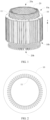
- FIG. 1 is a schematic diagram of a structure of a stator according to an embodiment of this application. As shown in FIG. 1 , the stator includes a stator iron core 10 and a stator winding 20.
- stator iron core 10 The following first describes a structure of the stator iron core 10 in this application with reference to FIG. 1 and FIG. 2 .
- FIG. 2 is a schematic diagram of a structure of a stator iron core according to an embodiment.
- a plurality of stator slots 11 are provided on an inner wall of the stator iron core 10, and a quantity of stator slots 11 may be denoted as Z.
- Z may be a natural number that is a multiple of 3, and may be specifically 54, 72, or the like. A specific value of Z may be selected based on a design of a motor.
- the Z stator slots 11 are provided on the inner wall of the stator iron core 10, and are evenly provided along a circumferential direction of the inner wall of the stator iron core 10.
- Any stator slot 11 extends along an axial direction of the stator iron core 10, and penetrates the inner wall of the stator iron core 10 along the axial direction of the stator iron core 10.
- the axial direction of the stator iron core 10 is a z direction shown in FIG. 1 .
- the stator iron core 10 is divided into a plug-in end 10a and an extension end 10b along the axial direction of the stator iron core 10, and any stator slot 11 may extend from the plug-in end 10a to the extension end 10b.
- the stator winding 20 may be formed by winding a plurality of hairpin coils.
- FIG. 3 is a schematic diagram of a structure of a hairpin coil according to an embodiment of this application.
- any hairpin coil 22 includes a first plug-in portion 221 and a second plug-in portion 222 that are connected to each other.
- the hairpin coil 22 includes the first plug-in portion 221, the second plug-in portion 222, a connection portion 223, a first bent portion 224, and a second bent portion 225.
- the first bent portion 224, the first plug-in portion 221, the connection portion 223, the second plug-in portion 222, and the second bent portion 225 are sequentially connected to form a U-shaped coil or a V-shaped coil.
- the hairpin coils 22 When the hairpin coils 22 are wound to form the stator winding 20, the hairpin coils 22 may be inserted into the stator slots 11 from the plug-in end 10a of the stator iron core 10, and extend out from the extension end 10b.
- connection portions 223 of the hairpin coils 22 are located on one side of the plug-in end 10a of the stator iron core 10 to form a crown end 20a of the stator winding 20, and first bent portions 224 and second bent portions 225 are located on one side of the extension end 10b of the stator iron core 10 to form a welding end 20b of the stator winding 20.
- first plug-in portion 221 and the second plug-in portion 222 that extend out of the stator iron core 10 may be bent to form the first bent portion 224 and the second bent portion 225.
- the first plug-in portion 221 and the second plug-in portion 222 form a flat-wire conductor 21, and a cross-sectional shape of the flat-wire conductor 21 may be a rectangle.
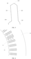
- FIG. 4 is a schematic top view of a structure of a flat-wire conductor 21 inserted into a stator slot 11 according to an embodiment of this application.
- N layers of flat-wire conductors 21 may be disposed in any stator slot 11 in an embodiment of this application.
- N is a multiple of 2.
- N may be 4, 6, 8, 10, or 12.
- FIG. 4 when N is 6, six layers of flat-wire conductors 21 are disposed in each stator slot 11. It can be understood that a quantity of layers of flat-wire conductors 21 shown in FIG.
- a quantity of layers of flat-wire conductors 21 in each stator slot 11 is not specifically limited herein.
- N layers of flat-wire conductors 21 are disposed in any stator slot 11, and from the bottom to an opening of the any stator slot 11, the N layers of flat-wire conductors 21 are denoted as an L 1 layer, an L 2 layer, ..., an L N-1 layer, and an L N layer.
- the opening of the stator slot 11 is provided close to the inner wall of the stator iron core 10
- the bottom of the stator slot 11 is provided close to an outer wall of the stator iron core 10.
- stator slots 11 of the stator iron core 10 indicates a larger quantity of layers of flat-wire conductors 21 in each stator slot 11 and a larger quantity of required coils 22.
- a quantity of hairpin coils 22 may be set based on the quantity Z of stator slots 11 and the quantity N of layers of flat-wire conductors 21 in the stator slot 11.
- all hairpin coils 22 forming the stator winding 20 may be divided into a plurality of coil groups.
- Each coil group includes a plurality of hairpin coils.
- a first plug-in portion 221 and a second plug-in portion 222 of any hairpin coil are respectively inserted into different stator slots 11 to form flat-wire conductors 21.
- a flat-wire conductor 21 located at a bottom layer of the stator slot 11 may be a first-layer flat-wire conductor, or a flat-wire conductor 21 located at an opening layer of the stator slot 11 may be a first-layer flat-wire conductor.
- the first-layer flat-wire conductor is located at the bottom layer.
- First plug-in portions 221 and second plug-in portions 222 of hairpin coils 22 forming the first-layer flat-wire conductor are inserted into first layers of stator slots 11 of adjacent poles and phases.
- the hairpin coils 22 inserted into the first layers of the stator slots 11 constitute a coil group.
- First plug-in portions 221 and second plug-in portions 222 of hairpin coils 22 for forming a second-layer flat-wire conductor to an (N-1)th-layer flat-wire conductor are respectively inserted into stator slots 11 of adjacent poles and phases to form adjacent layers of flat-wire conductors 21.
- Hairpin coils 22 forming same adjacent layers of flat-wire conductors 21 may constitute a coil group.
- First plug-in portions 221 and second plug-in portions 222 of hairpin coils 22 for forming an Nth-layer flat-wire conductor are inserted into Nth layers of stator slots 11, so that the hairpin coils 22 forming the Nth-layer flat-wire conductor may constitute a coil group.
- N is 10.
- Hairpin coils 22 forming a second-layer flat-wire conductor and a third-layer flat-wire conductor constitute a coil group
- hairpin coils 22 forming a fourth-layer flat-wire conductor and a fifth-layer flat-wire conductor constitute a coil group
- hairpin coils 22 forming a sixth-layer flat-wire conductor and a seventh-layer flat-wire conductor constitute a coil group
- hairpin coils 22 forming an eighth-layer flat-wire conductor and a ninth-layer flat-wire conductor constitute a coil group
- hairpin coils 22 forming a tenth-layer flat-wire conductor constitute a coil group.
- first plug-in portions 221 and second plug-in portions 222 of hairpin coils 22 forming each of the first-layer flat-wire conductor and the Nth-layer flat-wire conductor are inserted into a same layer, and first plug-in portions 221 and second plug-in portions 222 of hairpin coils 22 of each of other coil groups are inserted into adjacent layers.
- a coil group for forming the first-layer flat-wire conductor 21 may include hairpin coils 22 with two types of spans, and the spans of the two types of hairpin coils 22 are Z/2p+1 and Z/2p-q+1 respectively.
- Each of coil groups for forming the second-layer flat-wire conductor 21 to the (N-1)th-layer flat-wire conductor 21 includes hairpin coils 22 with one type of span, and a span of hairpin coils 22 in any coil group is Z/2p-1.
- a coil group for forming the Nth-layer flat-wire conductor 21 may include one type of hairpin coil 22, and a span of this type of hairpin coil 22 is Z/2p.
- a quantity of types of hairpin coils 22 forming the stator winding is N/2+2. Therefore, a total quantity of types of hairpin coils 22 of the stator winding in this application is small, and a quantity of types of hairpin coils 22 is effectively reduced.
- the hairpin coils 22 forming the stator winding may be connected to form an m-phase winding, m may be 2, 3, 4, 5, 6, or the like. To be specific, a corresponding quantity of phases of the flat-wire motor may be 2, 3, 4, 5, 6, or more.
- a three-phase winding is used as an example.
- the stator winding may be divided into a first-phase winding, a second-phase winding, and a third-phase winding that respectively correspond to a U-phase winding, a V-phase winding, and a W-phase winding.
- any phase of winding may include a plurality of phase units.
- phase units of the first-phase winding, phase units of the second-phase winding, and phase units of the third-phase winding are periodically arranged along the inner wall of the stator iron core in sequence.
- Each phase unit of each phase of winding is a phase of a pole, and a quantity of stator slots corresponding to each phase unit is a quantity of slots per phase per pole.
- stator winding 20 may be a single-phase winding, a three-phase winding, or a six-phase winding.
- the quantity Z of stator slots is equal to 2mpq.
- p is a quantity of magnetic poles of the stator winding, and p is a positive integer.
- mpq is a product of m, p, and q.
- the stator winding is a three-phase winding.
- m is 3
- a quantity 2p of magnetic poles is 6, and the quantity q of slots per phase per pole is 3.
- the quantity Z of stator slots on the stator iron core 10 is 54.
- each phase of winding includes q or 2q parallel branches, and hairpin coils 22 in any coil group are evenly distributed in parallel branches of each phase of winding.
- the quantity N of layers of flat-wire conductors in the stator slot 11 is less than or equal to 2q.
- spans of all parallel branches on the first-layer flat-wire conductor 21 to the Nth-layer flat-wire conductor 21 are Z/2p.
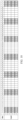
- FIG. 5 is a schematic diagram of a structure of connections of a U-phase winding according to an embodiment.
- the U-phase winding includes three parallel branches.
- the U-phase winding includes a plurality of phase units that are evenly disposed along a circumferential direction of the stator iron core at spacings. From the first-layer flat-wire conductor to the Nth-layer flat-wire conductor, every two layers of flat-wire conductors in each phase unit constitute a phase spread, and adjacent phase spreads of any phase unit are sequentially staggered by one stator slot. A quantity of phase spreads in one phase unit is not greater than q.
- a V-phase winding and a W-phase winding each are connected in a manner similar to that of the U-phase winding, and each include phase units and phase spreads that are disposed in a same manner.
- Each phase unit may include two, three, four, five, or more phase spreads. Adjacent phase spreads of any phase unit are staggered by one stator slot along a clockwise direction or a counterclockwise direction. To be specific, directions of staggered stator slots between adjacent phase spreads of one phase unit are the same. In this way, an equivalent pitch of the stator winding is less than a pole pitch of the stator winding to a maximum extent.
- a connection mode between phase units in each phase of winding is described by using a U phase as an example.
- a span of a first-layer flat-wire conductor in each parallel branch is a combination of Z/2p+1 and Z/2p-q+1
- a span of an Nth-layer flat-wire conductor in each parallel branch is Z/2p
- a span of a second-layer flat-wire conductor to an (N-1)th-layer flat-wire conductor in each parallel branch is Z/2p-1.
- a span of the first-layer flat-wire conductor to the Nth-layer flat-wire conductor in each parallel branch is Z/2p.
- a quantity of stator slots shown in FIG. 5 is used as an example.
- the span of the first-layer flat-wire conductor in each parallel branch is a combination of 10 and 7
- a span of every two of the second-layer flat-wire conductor to the (N-1)th-layer flat-wire conductor is 8, and the span of the Nth-layer flat-wire conductor is 9.
- the span of the first-layer flat-wire conductor to the Nth-layer flat-wire conductor in each parallel branch is 9.
- the quantity Z of stator slots may alternatively be 72.
- the span of the first-layer flat-wire conductor in each parallel branch is a combination of 13 and 9, a span of every two of the second-layer flat-wire conductor to the (N-1)th-layer flat-wire conductor is 11, and the span of the Nth-layer flat-wire conductor is 12.
- the span of the first-layer flat-wire conductor to the Nth-layer flat-wire conductor in each parallel branch is 12.
- one of a wire incoming end and a wire outgoing end of each parallel branch of each phase of winding is led out from a bottom-layer flat-wire conductor of a stator slot, and the other of the wire incoming end and the wire outgoing end of each parallel branch of each phase of winding is led out from a flat-wire conductor at an adjacent layer of the bottom-layer flat-wire conductor.
- the wire outgoing end of each parallel branch is led out from an L 1 -layer flat-wire conductor
- wire incoming ends of parallel branches of each phase of winding are located in adjacent stator slots, and wire outgoing ends of parallel branches of each phase of winding are located in adjacent stator slots.
- the U-phase winding in FIG. 5 is used as an example.
- Wire incoming ends of the three parallel branches are all led out from L 1 -layer flat-wire conductors in adjacent stator slots, and wire outgoing ends of the three parallel branches are all led out from L 1 -layer flat-wire conductors in adjacent stator slots.
- the wire incoming ends are led out from flat-wire conductors at same layers in adjacent stator slots, and the wire outgoing ends are led out from flat-wire conductors at same layers in adjacent stator slots, so that a busbar can be conveniently disposed, to implement a connection between the three parallel branches and the busbar.
- FIG. 6 and FIG. 7 show connection modes at ends of different phases of windings.
- a Y-shaped connection mode and a triangular connection mode may be used.
- an embodiment of this application provides a specific motor.
- the motor includes a stator and a rotor.
- the stator includes a stator iron core and a stator winding.
- 54 stator slots are evenly provided along a circumferential direction of an inner wall of the stator iron core.
- Six layers of flat-wire conductors are inserted into the stator slot along a radial direction of the stator iron core.
- first-layer flat-wire conductor In a direction from an outer wall of the stator iron core to an inner wall of the stator iron core, six layers of flat-wire conductors in each stator slot are denoted as a first-layer flat-wire conductor, a second-layer flat-wire conductor, a third-layer flat-wire conductor, a fourth-layer flat-wire conductor, a fifth-layer flat-wire conductor, and a sixth-layer flat-wire conductor.
- the first-layer flat-wire conductor is disposed close to the outer wall of the stator iron core
- the sixth-layer flat-wire conductor is disposed close to the inner wall of the stator iron core.
- every two first-layer flat-wire conductors are connected to each other, and two first-layer flat-wire conductors connected to each other are spaced apart by nine stator slots or six stator slots.
- two stator slots in which two first-layer flat-wire conductors connected to each other are respectively located, are spaced apart by nine stator slots or six stator slots.
- Second-layer flat-wire conductors are respectively connected to third-layer flat-wire conductors, and a second-layer flat-wire conductor and a third-layer flat-wire conductor that are connected to each other are spaced apart by seven stator slots.
- stator slots in which a second-layer flat-wire conductor and a third-layer flat-wire conductor that are connected to each other are located, are spaced apart by seven stator slots.
- Fourth-layer flat-wire conductors are respectively connected to fifth-layer flat-wire conductors, and a fourth-layer flat-wire conductor and a fifth-layer flat-wire conductor that are connected to each other are spaced apart by seven stator slots.
- two stator slots in which a fourth-layer flat-wire conductor and a fifth-layer flat-wire conductor that are connected to each other are located, are spaced apart by seven stator slots.
- the stator winding in this embodiment of this application may include a plurality of phases of windings.
- flat-wire conductors for forming each phase of winding may be divided into a plurality of phase units that are evenly disposed at spacings. From the first-layer flat-wire conductor to the sixth-layer flat-wire conductor, every two layers of flat-wire conductors in each phase unit constitute a phase spread.
- the first-layer flat-wire conductor and the second-layer flat-wire conductor may constitute a phase spread
- the third-layer flat-wire conductor and the fourth-layer flat-wire conductor may constitute a phase spread
- the fifth-layer flat-wire conductor and the sixth-layer flat-wire conductor may constitute a phase spread.
- two adjacent phase spreads are sequentially staggered by one stator slot.
- the phase spread formed by the first-layer flat-wire conductor and the second-layer flat-wire conductor and the phase spread formed by the third-layer flat-wire conductor and the fourth-layer flat-wire conductor are staggered by one stator slot
- the phase spread formed by the third-layer flat-wire conductor and the fourth-layer flat-wire conductor and the phase spread formed by the fifth-layer flat-wire conductor and the sixth-layer flat-wire conductor are staggered by one stator slot.
- Each phase of winding of the stator winding includes three parallel branches. One of a wire incoming end and a wire outgoing end of each parallel branch of each phase of winding is led out from the first-layer flat-wire conductor, and the other of the wire incoming end and the wire outgoing end of each parallel branch of each phase of winding is led out from the second-layer flat-wire conductor. Wire incoming ends of parallel branches of each phase of winding are located in adjacent stator slots, and wire outgoing ends of parallel branches of each phase of winding are located in adjacent stator slots.
- an embodiment of this application provides a specific motor.
- the motor includes a stator and a rotor.
- the stator includes a stator iron core and a stator winding.
- 72 stator slots are evenly provided along a circumferential direction of an inner wall of the stator iron core.
- Eight layers of flat-wire conductors are inserted into the stator slot along a radial direction of the stator iron core.
- first-layer flat-wire conductor In a direction from an outer wall of the stator iron core to an inner wall of the stator iron core, eight layers of flat-wire conductors in each stator slot are denoted as a first-layer flat-wire conductor, a second-layer flat-wire conductor, a third-layer flat-wire conductor, a fourth-layer flat-wire conductor, a fifth-layer flat-wire conductor, a sixth-layer flat-wire conductor, a seventh-layer flat-wire conductor, and an eighth-layer flat-wire conductor.
- the first-layer flat-wire conductor is disposed close to the outer wall of the stator iron core
- the eighth-layer flat-wire conductor is disposed close to the inner wall of the stator iron core.
- every two first-layer flat-wire conductors are connected to each other, and two first-layer flat-wire conductors connected to each other are spaced apart by 12 stator slots or eight stator slots.
- two stator slots in which two first-layer flat-wire conductors connected to each other are respectively located, are spaced apart by 12 stator slots or eight stator slots.
- Second-layer flat-wire conductors are respectively connected to third-layer flat-wire conductors, and a second-layer flat-wire conductor and a third-layer flat-wire conductor that are connected to each other are spaced apart by 10 stator slots.
- stator slots in which a second-layer flat-wire conductor and a third-layer flat-wire conductor that are connected to each other are located, are spaced apart by 10 stator slots.
- Fourth-layer flat-wire conductors are respectively connected to fifth-layer flat-wire conductors, and a fourth-layer flat-wire conductor and a fifth-layer flat-wire conductor that are connected to each other are spaced apart by 10 stator slots.
- two stator slots in which a fourth-layer flat-wire conductor and a fifth-layer flat-wire conductor that are connected to each other are located, are spaced apart by 10 stator slots.
- Sixth-layer flat-wire conductors are respectively connected to seventh-layer flat-wire conductors, and a sixth-layer flat-wire conductor and a seventh-layer flat-wire conductor that are connected to each other are spaced apart by 10 stator slots.
- two stator slots in which a sixth-layer flat-wire conductor and a seventh-layer flat-wire conductor that are connected to each other are located, are spaced apart by 10 stator slots.
- Every two eighth-layer flat-wire conductors are connected to each other, and two eighth-layer flat-wire conductors connected to each other are spaced apart by 11 stator slots.
- two stator slots in which two eighth-layer flat-wire conductors connected to each other are respectively located, are spaced apart by 11 stator slots.
- stator winding in this embodiment of this application may include a plurality of phases of windings.
- flat-wire conductors for forming each phase of winding may be divided into a plurality of phase units that are evenly disposed at spacings. From the first-layer flat-wire conductor to the sixth-layer flat-wire conductor, every two layers of flat-wire conductors in each phase unit constitute a phase spread.
- the first-layer flat-wire conductor and the second-layer flat-wire conductor may constitute a phase spread
- the third-layer flat-wire conductor and the fourth-layer flat-wire conductor may constitute a phase spread
- the fifth-layer flat-wire conductor and the sixth-layer flat-wire conductor may constitute a phase spread
- the seventh-layer flat-wire conductor and the eighth-layer flat-wire conductor constitute a phase spread.
- two adjacent phase spreads are sequentially staggered by one stator slot.
- the phase spread formed by the first-layer flat-wire conductor and the second-layer flat-wire conductor and the phase spread formed by the third-layer flat-wire conductor and the fourth-layer flat-wire conductor are staggered by one stator slot
- the phase spread formed by the fifth-layer flat-wire conductor and the sixth-layer flat-wire conductor and the phase spread formed by the seventh-layer flat-wire conductor and the eighth-layer flat-wire conductor are staggered by one stator slot.
- Each phase of winding of the stator winding includes four parallel branches. One of a wire incoming end and a wire outgoing end of each parallel branch of each phase of winding is led out from the first-layer flat-wire conductor, and the other of the wire incoming end and the wire outgoing end of each parallel branch of each phase of winding is led out from the second-layer flat-wire conductor. Wire incoming ends of parallel branches of each phase of winding are located in adjacent stator slots, and wire outgoing ends of parallel branches of each phase of winding are located in adjacent stator slots.
- an embodiment of this application provides a specific motor.
- the motor includes a stator and a rotor.
- the stator includes a stator iron core and a stator winding.
- 48 stator slots are evenly provided along a circumferential direction of an inner wall of the stator iron core.
- Four layers of flat-wire conductors are inserted into the stator slot along a radial direction of the stator iron core.
- first-layer flat-wire conductor In a direction from an outer wall of the stator iron core to an inner wall of the stator iron core, four layers of flat-wire conductors in each stator slot are denoted as a first-layer flat-wire conductor, a second-layer flat-wire conductor, a third-layer flat-wire conductor, and a fourth-layer flat-wire conductor.
- the first-layer flat-wire conductor is disposed close to the outer wall of the stator iron core
- the fourth-layer flat-wire conductor is disposed close to the inner wall of the stator iron core.
- every two first-layer flat-wire conductors are connected to each other, and two first-layer flat-wire conductors connected to each other are spaced apart by six stator slots or four stator slots.
- two stator slots in which two first-layer flat-wire conductors connected to each other are respectively located, are spaced apart by six stator slots or four stator slots.
- Second-layer flat-wire conductors are respectively connected to third-layer flat-wire conductors, and a second-layer flat-wire conductor and a third-layer flat-wire conductor that are connected to each other are spaced apart by four stator slots.
- stator slots in which a second-layer flat-wire conductor and a third-layer flat-wire conductor that are connected to each other are located, are spaced apart by four stator slots. Every two fourth-layer flat-wire conductors are connected to each other, and two fourth-layer flat-wire conductors connected to each other are spaced apart by eight stator slots.
- stator slots in which two fourth-layer flat-wire conductors connected to each other are respectively located, are spaced apart by eight stator slots.
- the stator winding in this embodiment of this application may include a plurality of phases of windings.
- flat-wire conductors for forming each phase of winding may be divided into a plurality of phase units that are evenly disposed at spacings. From the first-layer flat-wire conductor to the sixth-layer flat-wire conductor, every two layers of flat-wire conductors in each phase unit constitute a phase spread.
- the first-layer flat-wire conductor and the second-layer flat-wire conductor may constitute a phase spread
- the third-layer flat-wire conductor and the fourth-layer flat-wire conductor may constitute a phase spread.
- phase spreads are sequentially staggered by one stator slot.
- the phase spread formed by the first-layer flat-wire conductor and the second-layer flat-wire conductor and the phase spread formed by the third-layer flat-wire conductor and the fourth-layer flat-wire conductor are staggered by one stator slot.
- Each phase of winding of the stator winding includes two parallel branches. One of a wire incoming end and a wire outgoing end of each parallel branch of each phase of winding is led out from the first-layer flat-wire conductor, and the other of the wire incoming end and the wire outgoing end of each parallel branch of each phase of winding is led out from the second-layer flat-wire conductor. Wire incoming ends of parallel branches of each phase of winding are located in adjacent stator slots, and wire outgoing ends of parallel branches of each phase of winding are located in adjacent stator slots.
- an embodiment of this application further provides a powertrain.
- the powertrain includes a gearbox and the foregoing motor.
- the motor is connected to the gearbox in a transmission manner.
- a drive shaft of the motor may be connected to an input shaft of the gearbox in a transmission manner through a transmission component such as a coupling, to output a driving force from the motor to the gearbox.
- a vehicle provided in an embodiment of this application may include the foregoing powertrain.
- the powertrain is disposed in the vehicle, and provides power for operation of the vehicle.
- the vehicle may be specifically a new energy vehicle driven by electric energy.
- the new energy vehicle may be specifically a hybrid electric vehicle, a pure electric vehicle, a fuel cell electric vehicle, or the like, or may be a vehicle using a highly efficient energy storage device, such as a supercapacitor, a flywheel battery, or a flywheel energy storage device, as a source of electric energy.
- a stator iron core 10 includes 54 stator slots 11.
- a quantity of conductor layers in the stator slot 11 is 6.
- a quantity of poles of the stator is 6.
- a stator winding 20 is divided into a U phase, a V phase, and a W phase.
- a quantity of slots per phase per pole is 3.
- a quantity of parallel branches disposed in each phase of winding is 3.
- Hairpin coils of the stator winding 20 are divided into four coil groups in total. Hairpin coils forming a first layer through plug-in constitute a first coil group. Hairpin coils forming a second layer and a third layer through plug-in constitute a second coil group. Hairpin coils forming a fourth layer and a fifth layer through plug-in constitute a third coil group. Hairpin coils forming a sixth layer through plug-in constitute a fourth coil group.
- each stator slot 11 includes six layers of flat-wire conductors 21, a first layer is denoted as L1, a second layer is denoted as L2, a third layer is denoted as L3, a fourth layer is denoted as L4, a fifth layer is denoted as L5, and a sixth layer is denoted as L6.
- the first layer is a bottom layer of the stator slot 11, and the sixth layer is an opening layer.
- phase spread distribution shown in FIG. 5 is used as an example.
- a phase spread constituted by L1 and L2 flat-wire conductors in a slot 1, a slot 2, and a slot 3 is denoted as a phase spread A1.
- a phase spread constituted by L3 and L4 flat-wire conductors in a slot 54, the slot 1, and the slot 2 is denoted as a phase spread A2.
- a phase spread constituted by L5 and L6 flat-wire conductors in a slot 53, the slot 54, and the slot 1 is denoted as a phase spread A3.
- the phase spread A1, the phase spread A2, and the phase spread A3 constitute a phase unit A.
- phase spread B1 and L2 flat-wire conductors in a slot 10, a slot 11, and a slot 12 is denoted as a phase spread B1.
- a phase spread constituted by L3 and L4 flat-wire conductors in a slot 9, the slot 10, and the slot 11 is denoted as a phase spread B2.
- a phase spread constituted by L5 and L6 flat-wire conductors in a slot 8, the slot 9, and the slot 10 is denoted as a phase spread B3.
- the phase spread B1, the phase spread B2, and the phase spread B3 constitute a phase unit B.
- phase spread F1 and L2 flat-wire conductors in a slot 46, a slot 47, and a slot 48 is denoted as a phase spread F1.
- a phase spread constituted by L3 and L4 flat-wire conductors in a slot 45, the slot 46, and the slot 47 is denoted as a phase spread F2.
- a phase spread constituted by L5 and L6 flat-wire conductors in a slot 44, the slot 45, and the slot 46 is denoted as a phase spread F3.
- the phase spread F1, the phase spread F2, and the phase spread F3 constitute a phase unit F.
- a solid connection line represents a connection mode for the stator winding 20 at a crown end 20a
- a dashed connection line represents a connection mode for the stator winding 20 at a welding end 20b.
- wire incoming ends of three parallel branches U1, U2, and U3 of the U phase are L2-layer flat-wire conductors in the slot 1, the slot 2, and the slot 3 (the phase spread A1) respectively.
- the three parallel branches are respectively connected to different layers of flat-wire conductors in adjacent phase units in a same connection mode.
- wire outgoing ends of the three parallel branches are led out from L 1-layer flat-wire conductors in the slot 46, the slot 47, and the slot 48 respectively.
- a span of an L1-layer flat-wire conductor in each parallel branch is 10 or a combination of 10 and 7.
- a span of an L6-layer flat-wire conductor in each parallel branch is 9.
- a span of an L2-layer flat-wire conductor to an L5-layer flat-wire conductor during connection is 8
- the connection for the L2-layer flat-wire conductor to the L5-layer flat-wire conductor is also a connection between adjacent layers of flat-wire conductors.
- a parallel branch (denoted as a first parallel branch U1) whose wire incoming end is an L2-layer flat-wire conductor in the slot 1 is used as an example.
- an L3 layer in the slot 9 an L4 layer in a slot 18, an L5 layer in a slot 26, an L6 layer in a slot 35, an L6 layer in the slot 44, an L5 layer in the slot 35, an L4 layer in a slot 27, an L3 layer in the slot 18, an L2 layer in the slot 10, an L1 layer in the slot 1, an L1 layer in the slot 11, an L2 layer in a slot 20, an L3 layer in a slot 28, an L4 layer in a slot 37, an L5 layer in the slot 45, an L6 layer in the slot 54, an L6 layer in a slot 6, an L5 layer in the slot 54, an L4 layer in the slot 46, an L3 layer in the slot 37, an L2 layer in a slot
- connection modes for the other two parallel branches (denoted as a second parallel branch U2 and a third parallel branch U3), refer to the connection mode for the first parallel branch. Details are not described herein again.
- the V-phase winding and the W-phase winding each may be connected based on the connection mode for the U-phase winding.
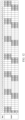
- FIG. 8 is a schematic diagram of a structure of connections of a U-phase winding according to this embodiment.
- a stator iron core 10 includes 72 stator slots 11.
- a quantity of conductor layers in the stator slot 11 is 8.
- a quantity of poles of the stator is 6.
- a stator winding 20 is divided into a U phase, a V phase, and a W phase.
- a quantity of slots per phase per pole is 4.
- a quantity of parallel branches disposed in each phase of winding is 4.
- Hairpin coils of the stator winding 20 are divided into five coil groups in total. Hairpin coils forming a first layer through plug-in constitute a first coil group.
- Hairpin coils forming a second layer and a third layer through plug-in constitute a second coil group. Hairpin coils forming a fourth layer and a fifth layer through plug-in constitute a third coil group. Hairpin coils forming a sixth layer and a seventh layer through plug-in constitute a fifth coil group. Hairpin coils forming an eighth layer through plug-in constitute a fifth coil group.
- wire incoming ends of four parallel branches U1, U2, U3, and U4 of the U phase are L2-layer flat-wire conductors in a slot 1, a slot 2, a slot 3, and a slot 4 (a phase spread A1) respectively.
- the four parallel branches are respectively connected to different layers of flat-wire conductors in adjacent phase units in a same connection mode.
- wire outgoing ends of the four parallel branches are led out from L1-layer flat-wire conductors in a slot 61, a slot 62, a slot 63, and a slot 64 respectively.
- a span of an L1-layer flat-wire conductor in each parallel branch is 13 or a combination of 13 and 9, a span of two adjacent layers of flat-wire conductors of an L2-layer flat-wire conductor to an L7-layer flat-wire conductor is 11, and a span of an L1-layer flat-wire conductor is 12.
- a span of two adjacent flat-wire conductors of the L1-layer flat-wire conductor to the L8-layer flat-wire conductor in each parallel branch is 12.
- FIG. 9 is a schematic diagram of a simplified structure of a U-phase winding according to this embodiment.
- a stator iron core 10 includes 48 stator slots 11.
- a quantity of conductor layers in the stator slot 11 is 4.
- a quantity of magnetic poles of the stator is 8.
- a stator winding 20 is divided into a U phase, a V phase, and a W phase.
- a quantity of slots per phase per pole is 2.
- a quantity of parallel branches disposed in each phase of winding is 2.
- the two parallel branches may be denoted as U1 and U2.
- Each phase unit of the U-phase winding includes two phase spreads. The two phase spreads are staggered by one stator slot along a clockwise or counterclockwise direction.
- Hairpin coils of the stator winding are divided into three coil groups in total. Hairpin coils forming a first layer through plug-in constitute a first coil group. Hairpin coils forming a second layer and a third layer through plug-in constitute a second coil group. Hairpin coils forming a fourth layer through plug-in constitute a third coil group.
- a plug-in mode for hairpin coils at each layer at a plug-in end refer to Embodiment 1.
- a span of hairpin coils in the first coil group at the plug-in end may be a combination of 7 and 5.
- a plug-in mode for hairpin coils in the second coil group to the fourth coil group at the plug-in end refer to Embodiment 1.
- a span of an L1-layer flat-wire conductor in each parallel branch is a combination of 7 and 5
- a span of an L2-layer flat-wire conductor and an L3-layer flat-wire conductor is 5
- a span of an L4-layer flat-wire conductor is 6.
- a span of two adjacent flat-wire conductors of the L1-layer flat-wire conductor to the L4-layer flat-wire conductor in each parallel branch is 6.
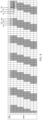
- FIG. 10 is a schematic diagram of a structure of connections for a stator winding of a stator in this comparative example.
- An equivalent pitch of the stator winding is a full pitch, and the equivalent pitch is 9.
- FIG. 11 is a schematic diagram of a structure of connections for a stator winding of a stator in this comparative example.
- An equivalent pitch of the stator winding is 8.
- FIG. 12 is a schematic diagram of a structure of connections for a stator winding of a stator in this comparative example.
- An equivalent pitch of the stator winding is 7.
- a winding system of a short-pitch winding in this application is compared with winding systems of a conventional full-pitch winding and a conventional short-pitch winding. It can be learned from related data in Table 1 that, compared with Comparative Example 1 to Comparative Example 3, in a continuous short-pitch winding in embodiments of this application, 5th-order/7th-order harmonics and 11th-order/13th-order harmonics are reduced by more than 80%. (6p)th-order torque ripple and (12p)th-order radial electromagnetic forces of the motor are mainly caused by 5th-order/7th-order harmonics and 11th-order/13th-order harmonics of the stator winding.
- stator in embodiments of this application has the following advantages:
Landscapes
- Engineering & Computer Science (AREA)
- Power Engineering (AREA)
- Windings For Motors And Generators (AREA)
Applications Claiming Priority (1)
| Application Number | Priority Date | Filing Date | Title |
|---|---|---|---|
| CN202310103375.XA CN118381223A (zh) | 2023-01-20 | 2023-01-20 | 电机、动力总成和车辆 |
Publications (1)
| Publication Number | Publication Date |
|---|---|
| EP4404437A1 true EP4404437A1 (de) | 2024-07-24 |
Family
ID=89661519
Family Applications (1)
| Application Number | Title | Priority Date | Filing Date |
|---|---|---|---|
| EP24152658.1A Pending EP4404437A1 (de) | 2023-01-20 | 2024-01-18 | Motor, antriebsstrang und fahrzeug |
Country Status (2)
| Country | Link |
|---|---|
| EP (1) | EP4404437A1 (de) |
| CN (1) | CN118381223A (de) |
Cited By (2)
| Publication number | Priority date | Publication date | Assignee | Title |
|---|---|---|---|---|
| CN119834496A (zh) * | 2025-01-07 | 2025-04-15 | 无锡星驱动力科技有限公司 | 一种扁线电机定子、扁线电机及车辆 |
| CN119834495A (zh) * | 2025-01-07 | 2025-04-15 | 无锡星驱动力科技有限公司 | 一种扁线电机定子、扁线电机及车辆 |
Citations (3)
| Publication number | Priority date | Publication date | Assignee | Title |
|---|---|---|---|---|
| CN115411860A (zh) * | 2022-08-12 | 2022-11-29 | 华为数字能源技术有限公司 | 定子、扁线电机、动力总成和车辆 |
| CN115498794A (zh) * | 2022-09-08 | 2022-12-20 | 华为数字能源技术有限公司 | 电机定子、扁线电机、动力总成和动力装置 |
| US20230009407A1 (en) * | 2021-10-30 | 2023-01-12 | Huawei Digital Power Technologies Co., Ltd. | Stator, flat wire motor, powertrain, and vehicle |
-
2023
- 2023-01-20 CN CN202310103375.XA patent/CN118381223A/zh active Pending
-
2024
- 2024-01-18 EP EP24152658.1A patent/EP4404437A1/de active Pending
Patent Citations (3)
| Publication number | Priority date | Publication date | Assignee | Title |
|---|---|---|---|---|
| US20230009407A1 (en) * | 2021-10-30 | 2023-01-12 | Huawei Digital Power Technologies Co., Ltd. | Stator, flat wire motor, powertrain, and vehicle |
| CN115411860A (zh) * | 2022-08-12 | 2022-11-29 | 华为数字能源技术有限公司 | 定子、扁线电机、动力总成和车辆 |
| CN115498794A (zh) * | 2022-09-08 | 2022-12-20 | 华为数字能源技术有限公司 | 电机定子、扁线电机、动力总成和动力装置 |
Cited By (2)
| Publication number | Priority date | Publication date | Assignee | Title |
|---|---|---|---|---|
| CN119834496A (zh) * | 2025-01-07 | 2025-04-15 | 无锡星驱动力科技有限公司 | 一种扁线电机定子、扁线电机及车辆 |
| CN119834495A (zh) * | 2025-01-07 | 2025-04-15 | 无锡星驱动力科技有限公司 | 一种扁线电机定子、扁线电机及车辆 |
Also Published As
| Publication number | Publication date |
|---|---|
| CN118381223A (zh) | 2024-07-23 |
Similar Documents
| Publication | Publication Date | Title |
|---|---|---|
| EP4175125A1 (de) | Stator, flachdrahtmotor, antriebsstrang und fahrzeug | |
| EP4572099A1 (de) | Stator, haarnadelmotor, antriebsstrang und fahrzeug | |
| CN218920099U (zh) | 定子、扁线电机、动力总成和车辆 | |
| WO2023124509A1 (zh) | 定子、扁线电机、动力总成和车辆 | |
| EP4404437A1 (de) | Motor, antriebsstrang und fahrzeug | |
| US12261496B2 (en) | Six-phase flat wire wave winding structure, six-phase motor, powertrain, and vehicle | |
| CN115765254A (zh) | 定子、扁线电机、动力总成和车辆 | |
| CN115498794B (zh) | 电机定子、扁线电机、动力总成和动力装置 | |
| US12301083B2 (en) | Motor, and stator and electric device thereof | |
| CN218920101U (zh) | 车辆、动力总成、扁线电机及其定子 | |
| JP2012085533A (ja) | 5相ジェネレータ | |
| US20250070603A1 (en) | Flat wire motor and stator thereof | |
| WO2024007709A1 (zh) | 定子、扁线电机、动力总成及车辆 | |
| JP3251626U (ja) | ステータ、フラットワイヤーモータ、パワートレーン及び車両 | |
| EP4145675A1 (de) | Haarnadelmotor, leistungsanordnung und fahrzeug | |
| CN113692685A (zh) | 定子绕组布置 | |
| US10756587B2 (en) | Polyphase AC electric motor | |
| CN218920102U (zh) | 定子、扁线电机、动力总成和车辆 | |
| CN118381224A (zh) | 电机、动力总成和车辆 | |
| US20250219490A1 (en) | Electrical device, and motor and stator thereof | |
| CN221597535U (zh) | 定子、扁线电机及动力总成 | |
| CN221597534U (zh) | 定子组件、扁线电机、动力总成及车辆 | |
| WO2024021885A1 (zh) | 定子组件、电机和车辆 | |
| CN117498585A (zh) | 定子组件、电机和车辆 | |
| CN221328690U (zh) | 一种扁线电机的定子、具有其的扁线电机和车辆 |
Legal Events
| Date | Code | Title | Description |
|---|---|---|---|
| PUAI | Public reference made under article 153(3) epc to a published international application that has entered the european phase |
Free format text: ORIGINAL CODE: 0009012 |
|
| STAA | Information on the status of an ep patent application or granted ep patent |
Free format text: STATUS: THE APPLICATION HAS BEEN PUBLISHED |
|
| AK | Designated contracting states |
Kind code of ref document: A1 Designated state(s): AL AT BE BG CH CY CZ DE DK EE ES FI FR GB GR HR HU IE IS IT LI LT LU LV MC ME MK MT NL NO PL PT RO RS SE SI SK SM TR |
|
| STAA | Information on the status of an ep patent application or granted ep patent |
Free format text: STATUS: REQUEST FOR EXAMINATION WAS MADE |
|
| 17P | Request for examination filed |
Effective date: 20250124 |