EP4579877A1 - Batteriepack und elektrische vorrichtung - Google Patents
Batteriepack und elektrische vorrichtung Download PDFInfo
- Publication number
- EP4579877A1 EP4579877A1 EP23859227.3A EP23859227A EP4579877A1 EP 4579877 A1 EP4579877 A1 EP 4579877A1 EP 23859227 A EP23859227 A EP 23859227A EP 4579877 A1 EP4579877 A1 EP 4579877A1
- Authority
- EP
- European Patent Office
- Prior art keywords
- sidewall
- projection
- cell
- thermally conductive
- battery pack
- Prior art date
- Legal status (The legal status is an assumption and is not a legal conclusion. Google has not performed a legal analysis and makes no representation as to the accuracy of the status listed.)
- Pending
Links
Images


Classifications
-
- H—ELECTRICITY
- H01—ELECTRIC ELEMENTS
- H01M—PROCESSES OR MEANS, e.g. BATTERIES, FOR THE DIRECT CONVERSION OF CHEMICAL ENERGY INTO ELECTRICAL ENERGY
- H01M50/00—Constructional details or processes of manufacture of the non-active parts of electrochemical cells other than fuel cells, e.g. hybrid cells
- H01M50/20—Mountings; Secondary casings or frames; Racks, modules or packs; Suspension devices; Shock absorbers; Transport or carrying devices; Holders
-
- H—ELECTRICITY
- H01—ELECTRIC ELEMENTS
- H01M—PROCESSES OR MEANS, e.g. BATTERIES, FOR THE DIRECT CONVERSION OF CHEMICAL ENERGY INTO ELECTRICAL ENERGY
- H01M10/00—Secondary cells; Manufacture thereof
- H01M10/60—Heating or cooling; Temperature control
- H01M10/61—Types of temperature control
- H01M10/613—Cooling or keeping cold
-
- H—ELECTRICITY
- H01—ELECTRIC ELEMENTS
- H01M—PROCESSES OR MEANS, e.g. BATTERIES, FOR THE DIRECT CONVERSION OF CHEMICAL ENERGY INTO ELECTRICAL ENERGY
- H01M10/00—Secondary cells; Manufacture thereof
- H01M10/60—Heating or cooling; Temperature control
- H01M10/65—Means for temperature control structurally associated with the cells
- H01M10/653—Means for temperature control structurally associated with the cells characterised by electrically insulating or thermally conductive materials
-
- H—ELECTRICITY
- H01—ELECTRIC ELEMENTS
- H01M—PROCESSES OR MEANS, e.g. BATTERIES, FOR THE DIRECT CONVERSION OF CHEMICAL ENERGY INTO ELECTRICAL ENERGY
- H01M10/00—Secondary cells; Manufacture thereof
- H01M10/60—Heating or cooling; Temperature control
- H01M10/65—Means for temperature control structurally associated with the cells
- H01M10/655—Solid structures for heat exchange or heat conduction
- H01M10/6556—Solid parts with flow channel passages or pipes for heat exchange
- H01M10/6557—Solid parts with flow channel passages or pipes for heat exchange arranged between the cells
-
- H—ELECTRICITY
- H01—ELECTRIC ELEMENTS
- H01M—PROCESSES OR MEANS, e.g. BATTERIES, FOR THE DIRECT CONVERSION OF CHEMICAL ENERGY INTO ELECTRICAL ENERGY
- H01M10/00—Secondary cells; Manufacture thereof
- H01M10/60—Heating or cooling; Temperature control
- H01M10/65—Means for temperature control structurally associated with the cells
- H01M10/656—Means for temperature control structurally associated with the cells characterised by the type of heat-exchange fluid
- H01M10/6561—Gases
-
- H—ELECTRICITY
- H01—ELECTRIC ELEMENTS
- H01M—PROCESSES OR MEANS, e.g. BATTERIES, FOR THE DIRECT CONVERSION OF CHEMICAL ENERGY INTO ELECTRICAL ENERGY
- H01M10/00—Secondary cells; Manufacture thereof
- H01M10/60—Heating or cooling; Temperature control
- H01M10/65—Means for temperature control structurally associated with the cells
- H01M10/658—Means for temperature control structurally associated with the cells by thermal insulation or shielding
-
- H—ELECTRICITY
- H01—ELECTRIC ELEMENTS
- H01M—PROCESSES OR MEANS, e.g. BATTERIES, FOR THE DIRECT CONVERSION OF CHEMICAL ENERGY INTO ELECTRICAL ENERGY
- H01M50/00—Constructional details or processes of manufacture of the non-active parts of electrochemical cells other than fuel cells, e.g. hybrid cells
- H01M50/20—Mountings; Secondary casings or frames; Racks, modules or packs; Suspension devices; Shock absorbers; Transport or carrying devices; Holders
- H01M50/204—Racks, modules or packs for multiple batteries or multiple cells
- H01M50/207—Racks, modules or packs for multiple batteries or multiple cells characterised by their shape
- H01M50/209—Racks, modules or packs for multiple batteries or multiple cells characterised by their shape adapted for prismatic or rectangular cells
-
- H—ELECTRICITY
- H01—ELECTRIC ELEMENTS
- H01M—PROCESSES OR MEANS, e.g. BATTERIES, FOR THE DIRECT CONVERSION OF CHEMICAL ENERGY INTO ELECTRICAL ENERGY
- H01M50/00—Constructional details or processes of manufacture of the non-active parts of electrochemical cells other than fuel cells, e.g. hybrid cells
- H01M50/50—Current conducting connections for cells or batteries
- H01M50/502—Interconnectors for connecting terminals of adjacent batteries; Interconnectors for connecting cells outside a battery casing
-
- H—ELECTRICITY
- H01—ELECTRIC ELEMENTS
- H01M—PROCESSES OR MEANS, e.g. BATTERIES, FOR THE DIRECT CONVERSION OF CHEMICAL ENERGY INTO ELECTRICAL ENERGY
- H01M2220/00—Batteries for particular applications
- H01M2220/20—Batteries in motive systems, e.g. vehicle, ship, plane
-
- Y—GENERAL TAGGING OF NEW TECHNOLOGICAL DEVELOPMENTS; GENERAL TAGGING OF CROSS-SECTIONAL TECHNOLOGIES SPANNING OVER SEVERAL SECTIONS OF THE IPC; TECHNICAL SUBJECTS COVERED BY FORMER USPC CROSS-REFERENCE ART COLLECTIONS [XRACs] AND DIGESTS
- Y02—TECHNOLOGIES OR APPLICATIONS FOR MITIGATION OR ADAPTATION AGAINST CLIMATE CHANGE
- Y02E—REDUCTION OF GREENHOUSE GAS [GHG] EMISSIONS, RELATED TO ENERGY GENERATION, TRANSMISSION OR DISTRIBUTION
- Y02E60/00—Enabling technologies; Technologies with a potential or indirect contribution to GHG emissions mitigation
- Y02E60/10—Energy storage using batteries
Definitions
- This application relates to the technical field of energy storage, and in particular, to a battery pack and an electrical device.
- a battery pack generates a lot of heat during operation. To prevent overheating of the battery pack, the heat of the battery pack needs to be dissipated.
- a conventional heat dissipation method currently available is to add heat sinks between battery cells. However, in this heat dissipation method, the heat dissipation speed is relatively slow, the heat dissipation effect for the battery pack is limited, and an adverse effect is caused to the battery device that uses the battery pack.
- the housing assembly includes a first housing.
- the first housing includes a first wall, a first sidewall, a second sidewall, a third sidewall, and a fourth sidewall.
- the first wall is connected to the first sidewall, the second sidewall, the third sidewall, and the fourth sidewall to form the first space.
- the first opening is provided on the first sidewall.
- the second opening is provided on the second sidewall.
- the first sidewall and the second sidewall are arranged along the first direction.
- the third sidewall and the fourth sidewall are arranged along a second direction.
- the first direction is perpendicular to the second direction.
- a projection of the first opening overlaps with a projection of the second opening, thereby shortening the path of the first channel, allowing external air to quickly pass through the first channel to take away the heat of the cell assembly, and improving the heat dissipation efficiency.
- the length of the first channel is the shortest and the air volume into and out of the first opening and the second opening is large, thereby further improving heat dissipation.
- the first connecting piece includes a first part.
- the first channel is disposed in the first part.
- the first part is located between the third sidewall and the fourth sidewall.
- the cell assembly includes a first cell row.
- the first cell row includes a plurality of battery cells stacked along the first direction.
- Each battery cell includes a cell housing, an electrode assembly disposed in the cell housing, and an electrode terminal connected to the electrode assembly and led out of the cell housing.
- the first part includes a first surface and a second surface disposed along a second direction.
- a projection of the first surface overlaps with a projection of the first cell row
- a projection of the second surface overlaps with a projection of the second cell row.
- the heat of the first cell row is conducted by the first surface
- the heat of the second cell row is conducted by the second surface, thereby implementing heat dissipation.
- a projection of the first cell row is located within a projection of the first surface.
- a projection of the second cell row is located within a projection of the second surface.
- a thermal adhesive is disposed between the first part and the first cell row to facilitate rapid conduction of heat to the first connecting piece, thereby further improving the heat dissipation.
- the first part is further provided with a second channel.
- the second channel runs through the first part along the first direction.
- the first channel and the second channel are spaced apart along the third direction. With the second channel disposed, the first channel and the second channel can work together to dissipate heat for the battery cell, thereby further improving the heat dissipation efficiency.
- the battery pack further includes a first insulation piece and a first adapter plate.
- the first adapter plate is connected to the electrode terminal.
- the first insulation piece is disposed on one side, facing away from the cell assembly, of the first adapter plate.
- a projection of the first adapter plate overlaps with a projection of the first insulation piece
- a projection of the electrode terminal overlaps with the projection of the first insulation piece, thereby providing insulative protection for a first electrically conductive strip and the electrode terminal.
- the first thermally conductive layer and the second thermally conductive layer are made of the same material.
- the first thermally conductive layer and the second thermally conductive layer are formed by curing a flowing insulation material that flows in.
- An embodiment of this application further provides an electrical device, including the battery pack disclosed in any one of the embodiments described above.
- the heat of the cell assembly in the battery pack and the electrical device flows in the first channel through external air and is dissipated to an external environment, thereby improving the heat dissipation efficiency of the cell assembly.
- a component considered to be “disposed on” or “provided on” another component may be directly positioned on the other component or may be positioned on the other component through an intermediate component in between.
- a component considered to be “connected to” another component may be directly connected to the other component or may be connected to the other component through an intermediate component.
- the term "perpendicular” is a description of an ideal state between two components. In the actual production or use state, one component may be approximately perpendicular to another component.
- the term “perpendicular” may represent an angle of 90° ⁇ 10° between two straight lines, or a dihedral angle of 90° ⁇ 10° between two planes, or an angle of 90° ⁇ 10° between a straight line and a plane.
- Two components described as "perpendicular" to each other may be not absolute straight lines or planes, but may be roughly straight lines or planes.
- An object is considered to be a "straight line” or "plane” if the overall extension direction of the object is a straight line or plane as viewed from a macro perspective.
- the battery pack includes a housing assembly, a first connecting piece, and a cell assembly.
- the housing assembly includes a first space.
- the housing assembly is provided with a first opening and a second opening both communicating with the first space.
- the first connecting piece is accommodated in the first space.
- the first connecting piece is provided with a first channel.
- the first opening communicates to the second opening through the first channel.
- At least a part of the cell assembly is disposed in the first space.
- a projection of the first opening and a projection of the cell assembly are spaced apart from each other, a projection of the second opening the projection of the cell assembly are spaced apart from each other.
- the first direction is a stacking direction of battery cells in the cell assembly.
- the heat of the cell assembly in the battery pack flows in the first channel through external air and is dissipated to an external environment, thereby improving the heat dissipation efficiency of the cell assembly.
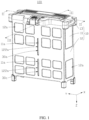
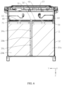
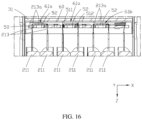
- an embodiment of this application provides a battery pack 100, including a housing assembly 10, a cell assembly 20, and a first connecting piece 30.
- the housing assembly 10 includes a first space. Both the cell assembly 20 and the first connecting piece 30 are disposed in the first space.
- the housing assembly 10 is further provided with a first opening 11a and a second opening 11b, the first opening 11a and a second opening 11b are communicate to the first space.
- the first connecting piece 30 is provided with a first channel 30a. One end of the first channel 30a is connected to the first opening 11a. Another end of the first channel is connected to the second opening 11b.
- a part of the surfaces of the cell assembly 20 are facing toward the first connecting piece 30, and can dissipate heat through the first connecting piece 30. External air can enter the first channel 30a from the first opening 11a, and be expelled from the second opening 11b; or, external air can enter the first channel 30a from the second opening 11b, and be expelled from the first opening 11a.
- a part of the heat of the cell assembly 20 flows in the first channel 30a through the external air, and is dissipated to the external environment.
- the remaining surfaces are facing toward the inner wall of the housing assembly 10. A part of the heat is dissipated to the external environment through the inner wall of the housing assembly 10. In this way, each surface of the cell assembly 20 can exchange heat with the external environment, thereby improving the heat dissipation efficiency of the cell assembly 20.
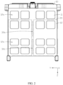
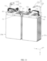
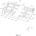
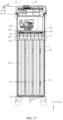
- the plurality of first holes 12a make the second housing 12 assume a mesh-like structure, thereby reducing the material consumption of the second housing 12, and in turn, reducing the weight of the second housing 12, and making the battery pack 100 lighter. Understandably, the second housing 12 itself can dissipate heat for the first housing 11.
- the fifth sidewall 122 is provided with a third opening 122a
- the sixth sidewall 123 is provided with a fourth opening 123a.
- the projections of the third opening 122a and the fourth opening 123a overlap with the projection of the first channel 30a.
- the projection of the first opening 11a overlaps with the projection of the third opening 122a.
- the projection of the first opening 11a overlaps with the projection of the third opening 122a, thereby increasing the amount of air that flows in and out.
- the projection of the second opening 11b overlaps with the projection of the fourth opening 123a.
- the first housing 11 is in clearance fit or in interference fit with the second housing 12. In this way, the outer surface of the first housing 11 closely fits the inner surface of the second housing 12, thereby making it convenient to fix the first housing 11.
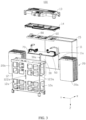
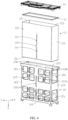
- the housing assembly 10 further includes a third housing 13 and a bracket 14.
- the bracket 14 connects the first housing 11 and the second housing 12, and the third housing 13 is connected to the bracket 14, so that the first housing 11 is enclosed in the second housing 12.
- a fixing bulge 12b is disposed at a junction between the seventh sidewall 124 and the fifth sidewall 122.
- a fixing bulge 12b is provided at a junction between the seventh sidewall 124 and the sixth sidewall 123.
- a fixing bulge 12b is provided at a junction between the eighth sidewall 125 and the fifth sidewall 122.
- a fixing bulge 12b is provided at the junction between the eighth sidewall 125 and the sixth sidewall 123.
- the bracket 14 is connected to the first sidewall 112, the second sidewall 113, the third sidewall 114, and the fourth sidewall 115.
- the bracket 14 and the first wall 111 are arranged along the third direction Z.
- the bracket 14 is fixedly connected to the fixing bulge 12b by a fastener, so as to constrain the first housing 11 within the second housing 12.
- the third housing 13 is fixedly connected to one side, facing away from the second housing 12, of the bracket 14. When the second housing 12 and/or the third housing 13 need to be replaced, the second housing 12 and/or the third housing 13 can be disassembled and replaced by loosening the fasteners.
- the battery pack 100 further includes a circuit board 40.
- the circuit board 40 is disposed in the third housing 13.
- the circuit board 40 is electrically connected to the cell assembly 20.
- the circuit board 40 includes a battery management system (BMS) assembly.
- BMS assembly includes a plurality of electronic components.
- the plurality of electronic components can implement functions such as dada collection, control, protection, communication, state-of-charge (SoC) calculation, signal transmission, and power transmission for the battery.
- a first adhesive layer (not shown in the drawing) is disposed between the first sealing part 15a and the inner surface of the first housing 11, and a first adhesive layer is disposed between the second sealing part 15b and the outer surface of the first housing 11.
- the sealing element 15 is bonded and fixed to the first housing 11 by the first adhesive layer.
- the first adhesive layer includes a sealing adhesive.
- a second adhesive layer (not shown in the drawing) is disposed between the first sealing part 15a and the bracket 14.
- a second adhesive layer is disposed between the second sealing part 15b and the inner surface of the second housing 12.
- a second adhesive layer is disposed between the third sealing part 15c and the bracket 14.
- the second adhesive layer includes a sealing adhesive. The second adhesive layer disposed can strengthen the connection between the bracket 14 and the sealing element 15, and the connection between the second housing 12 and the sealing element, and reduce the risk that impurities such as moisture enter the first housing 11 and cause a short circuit of the battery.
- a first recess 12c is disposed at one end of the fifth sidewall 122, the sixth sidewall 123, the seventh sidewall 124, and the eighth sidewall 125, separately, the end being an end facing away from the second wall 121.
- the second sealing part 15b is disposed in the first recess 12c. With the second sealing part 15b disposed in the first recess 12c, the extension path of the clearance between the second sealing part 15b and the sidewall of the second housing 12 is increased, the moisture entering the first housing 11 is reduced, and the risk of a short circuit of the battery is further reduced.
- one end of the sixth sidewall 123 is recessed along the first direction X to form the first recess 12c, the end of the sixth sidewall 123 being an end facing away from the second wall 121.
- the projection of the second sealing part 15b overlaps with the projection of the first recess 12c.
- the projection of the second sealing part 15b is located within the projection of the first recess 12c. Understandably, the depth of the first recess 12c along the first direction X may be an added extension path.
- the cell assembly 20 includes a first cell row 20a.
- the first cell row 20a is disposed between the first sidewall 112 and the second sidewall 113.
- the first cell row 20a is disposed between the third sidewall 114 and a part of the first connecting piece 30.
- the first cell row 20a is also disposed between the first wall 111 and a part of the first connecting piece 30.
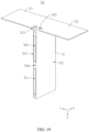
- the first cell row 20a includes a plurality of battery cells 21 stacked along the first direction X.
- the cell housing 211 includes a first shell 2111 and a second shell 2112.
- the first shell 2111 is connected to the second shell 2112.
- a recess is disposed in at least one of the first shell 2111 or the second shell 2112, and is configured to accommodate the electrode assembly 212.
- the first shell 2111 and the second shell 2112 may be folded along a junction in between (indicated by the dashed line). In this way, the first shell 2111 and the second shell 2112 coincide to form a first part 211a, so as to enclose the electrode assembly 212.
- the rim of the first shell 2111 extends outward to form a plurality of first extension portions 2113.
- the rim of the second shell 2112 extends outward to form a plurality of second extension portions 2114.
- the second part 211b includes a first sealing portion 2115 and a second sealing portion 2116.
- the first sealing portion 2115 is disposed opposite to the junction.
- the electrode terminal 213 extends out of the first part 211a from the first sealing portion 2115.
- the second part 211b includes two second sealing portions 2116.
- the two second sealing portions 2116 are arranged along the second direction Y.
- the second part 211b includes one first sealing portion 2115.
- the battery cell 21 includes two electrode terminals 213.
- the two electrode terminals 213 extend out of the cell housing 211 from the first sealing portion 2115.
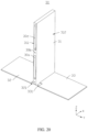
- the first shell 2111 is separate from the second shell 2112.
- the second part 211b includes two first sealing portions 2115.
- the two first sealing portions 2115 are arranged along the third direction Z.
- the battery cell 21 includes two electrode terminals 213. One of the electrode terminals 213 extends out of the cell housing 211 from one of the first sealing portions 2115, and the other electrode terminal 213 extends out of the cell housing 211 from the other first sealing portion 2115.
- the two electrode terminals 213 are arranged along the third direction Z.
- the electrode terminal 213 includes a welding portion 213a extending out of the cell housing 211.
- the welding portion 213a is formed by bending the electrode terminal 213.
- the electrode terminals 213 include a first terminal 213b and a second terminal 213c.
- the polarity of the first terminal 213b is opposite to the polarity of the second terminal 213c.
- One of the first terminal 213b or the second terminal 213c is a positive terminal, and the other is a negative terminal.
- a projection of the welding portion 213a of the first terminal 213b of a battery cell 21 at least partially overlaps with a projection of the welding portion 213a of the second terminal 213c of an adjacent battery cell 21.
- the battery cell 21 includes a first lateral surface 21a, a second lateral surface 21b, a third lateral surface 21c, a fourth lateral surface 21d, a fifth lateral surface 21e, and a sixth lateral surface 21f.
- the first lateral surface 21a and the second lateral surface 21b are arranged along the first direction X.
- the third lateral surface 21c and the fourth lateral surface 21d are arranged along the second direction Y.
- the fifth lateral surface 21e and the sixth lateral surface 21f are arranged along the third direction Z.
- the electrode terminal 213 extends out from the fifth lateral surface 21e.
- the first lateral surface 21a is disposed toward the first sidewall 112.
- the second lateral surface 21b is disposed toward the second sidewall 113.
- the third lateral surface 21c is disposed toward the third sidewall 114.
- the fourth lateral surface 21d is disposed toward a part of the first connecting piece 30.
- the fifth lateral surface 21e is disposed toward another part of the first connecting piece 30.
- the sixth lateral surface 21f is disposed toward the first wall 111.
- the first lateral surface 21a, the second lateral surface 21b, the third lateral surface 21c, the fourth lateral surface 21d, the fifth lateral surface 21e, and the sixth lateral surface 21f of the battery cell 21 are all allowed to transfer heat to the external environment, thereby improving the heat dissipation of the cell assembly 20, and reducing the temperature of the battery pack 100. Understandably, the above method is also applicable to a scenario of a plurality of battery cells 21.
- the first cell row 20a further includes a first thermally conductive piece 22a.
- Each battery cell 21 is thermally connected to at least one first thermally conductive piece 22a.
- the first thermally conductive piece 22a is thermally connected to the first housing 11 and the first connecting piece 30. In this way, the heat of the battery cell 21 is transferred to the first housing 11 and the first connecting piece 30 through the first thermally conductive piece 22a, and then the heat of the battery cell 21 is dissipated through the first housing 11 and the first connecting piece 30.
- the first thermally conductive piece 22a is connected to the first lateral surface 21a or the second lateral surface 21b, and is bent and extended to the third lateral surface 21c, the fourth lateral surface 21d, and the sixth lateral surface 21f.
- the heat of the battery cell 21 is transferred to the first connecting piece 30 and the first housing 11 through the first thermally conductive piece 22a, thereby improving the heat dissipation effect of the battery cell 21.
- the first thermally conductive piece 22a does not need to extend to the fourth lateral surface 21d, and the fourth lateral surface 21d is directly thermally connected to the first connecting piece 30.
- the thermal connection may be heat-transfer connection implemented by a thermal adhesive or the like.
- the thermal connection may be direct-contact connection implemented between two structural components.
- the first thermally conductive piece 22a is in contact with and connected to the first housing 11 and the first connecting piece 30.
- the first thermally conductive piece 22a includes an aluminum sheet.
- an elastic piece 23 is further disposed between adjacent first thermally conductive pieces 22a. When the battery cell 21 expands, the elastic piece 23 can be compressed to provide an expansion space for the battery cell 21.
- the elastic piece 23 includes foam.
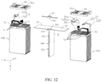
- the cell assembly 20 further includes a second cell row 20b.
- the first cell row 20a and the second cell row 20b are arranged along the second direction Y.
- the first connecting piece 30 is disposed between the first cell row 20a and the second cell row 20b.
- the second cell row 20b is disposed between a part of the first connecting piece 30 and the fourth sidewall 115.
- the second cell row 20b is disposed between the first sidewall 112 and the second sidewall 113.
- the second cell row 20b is also disposed between the first wall 111 and a part of the first connecting piece 30.
- the first connecting piece 30 is thermally connected to the first cell row 20a and the second cell row 20b, and can transfer the heat of the first cell row 20a and the second cell row 20b to the first connecting piece 30 simultaneously, and quickly dissipate heat through the first channel 30a.
- the battery cells 21 of the second cell row 20b assume the same structure as the battery cells 21 of the first cell row 20a.
- the second cell row 20b includes a plurality of battery cells 21 stacked along the first direction X. Each battery cell 21 is in contact with and connected to the first connecting piece 30 and the first housing 11.
- the second cell row 20b further includes a second thermally conductive piece 22b.
- the second thermally conductive piece 22b assumes basically the same structure as the first thermally conductive piece 22a.
- the first connecting piece 30 is connected to the first thermally conductive piece 22a, the first connecting piece 30 is connected to the second thermally conductive piece 22b, and the first connecting piece 30 is located between the first thermally conductive piece 22a and the second thermally conductive piece 22b, so as to improve the heat dissipation of the cell assembly 20.
- the battery pack 100 further includes a first electrically conductive piece 24.
- One end of the first electrically conductive piece 24 is connected to the first cell row 20a.
- Another end of the first electrically conductive piece is connected to the second cell row 20b.
- one end of the first electrically conductive piece 24 is connected to the first terminal 213b of the battery cell 21 in the first cell row 20a, and another end of the first electrically conductive piece is connected to the second terminal 213c of the battery cell 21 in the second cell row 20b, thereby implementing series connection between the first cell row 20a and the first cell row 20a.
- the battery pack 100 further includes a first electrical connecting portion 53 connected to the first adapter plate 50.
- the first electrical connecting portion 53 includes a first electrically conductive portion 531 and a first insulation portion 532.
- the first insulation portion 532 is sleeved on the first electrically conductive portion 531. Both ends of the first electrically conductive portion 531 extend out of the first insulation portion 532.
- One end of the first electrically conductive portion 531 is connected to the first electrically conductive strip 52, and another end is connected to the circuit board 40.
- the first electrically conductive portion 531 and the first electrically conductive strip 52 are a one-piece structure.
- the first adapter plate 50 is further provided with a first sampling harness 54.
- the first sampling harness 54 is connected to the circuit board 40.
- the first sampling harness 54 can collect information such as current, voltage, and temperature of the battery cell 21.
- the first main body 61 covers the first electrically conductive strip 52 and the electrode terminal 213.
- the projection of the first side plate 62 overlaps with the projection of the first adapter plate 50.
- the projection of the first electrically conductive strip 52 is located within the projection of the first side plate 62.
- the first main body 61 is provided with a fifth opening 611.
- the fifth opening 611 runs through the surface of the first main body 61 along the third direction Z.
- the first electrical connecting portion 53 passes through the fifth opening 611, and then extends to one side of the first main body 61, the one side of the first main body 61being a side facing away from the first adapter plate 50.
- the first main body 61 is provided with a first bulge 612.
- the first bulge 612 is disposed at the edge of the fifth opening 611. Through the first bulge 612, the first electrical connecting portion 53 is constrained.
- the projection of the first electrically conductive portion 531 is located within the projection of the first bulge 612.
- the first bulge 612 insulates one end of the first electrically conductive portion 531, the end extending out of the first insulation portion 532, thereby reducing the risk of a short circuit of the part that extends out of the first insulation portion 532 on the first electrically conductive portion 531.
- the projection of the first insulation portion 532 overlaps with the projection of the first bulge 612, thereby further improving the insulation of the extension-out part of the first electrically conductive portion 531.
- a part of the structure of the second bulge 614 is located between the first electrically conductive piece 24 and the first connecting piece 30, thereby reducing the risk of a short circuit between the first electrically conductive piece 24 and the first connecting piece 30.
- the first main body 61 is provided with a seventh opening 615.
- the seventh opening 615 runs through the surface of the first main body 61.
- a third bulge 616 is disposed at the edge of the seventh opening 615.
- the first sampling harness 54 passes through the first main body 61 through the seventh opening 615, and is connected to the circuit board 40.
- a first thermally conductive layer 101 is disposed between the cell housing 211 and the first adapter plate 50.
- a projection of the electrode terminal 213 overlaps with a projection of the first thermally conductive layer 101.
- the electrode terminal 213 between the cell housing 211 and the first adapter plate 50 is fixed, insulated, and enabled to conduct heat.
- the first thermally conductive layer 101 is formed by pouring and curing an insulation material in the battery pack 100.
- the first thermally conductive layer 101 includes at least one of a potting glue or a foam adhesive.
- the first thermally conductive layer 101 is formed by pouring and curing a potting glue in the battery pack 100.
- the first thermally conductive layer 101 is formed by foaming a foam adhesive.
- the first thermally conductive layer 101 includes a resin, and is formed by heating and melting the resin, pouring the flowable resin into the clearance between the cell housing 211 and the first adapter plate 50, and then curing.
- a second thermally conductive layer 102 is disposed between the first insulation piece 60 and the first adapter plate 50.
- the projection of the welding portion 213a of the electrode terminal 213 overlaps with the projection of the second thermally conductive layer 102.
- the projection of the first electrically conductive strip 52 overlaps with the projection of the second thermally conductive layer 102.
- the projection of the first electrically conductive piece 24 overlaps with the projection of the second thermally conductive layer 102.
- the second thermally conductive layer 102 is formed by pouring and curing an insulation material in the battery pack 100.
- the second thermally conductive layer 102 includes at least one of a potting glue or a foam adhesive.
- the second thermally conductive layer 102 is formed by pouring and curing a potting glue in the battery pack 100.
- the second thermally conductive layer 102 is formed by foaming a foam adhesive.
- the second thermally conductive layer 102 includes a resin, and is formed by heating and melting the resin, pouring the flowable resin into the clearance between the first insulation piece 60 and the first adapter plate 50, and then curing.
- the third thermally conductive layer includes a resin, and is formed by heating and melting the resin, pouring the flowable resin into the clearance between the first insulation piece 60 and the first connecting piece 30, and then curing.
- the third thermally conductive layer is injection-molded by putting a flowable resin into the clearance between the first insulation piece 60 and the first connecting piece 30 and then curing. The third thermally conductive layer fills the clearance between the first insulation piece 60 and the first connecting piece 30, strengthens the insulative protection between the first insulation piece 60 and the first connecting piece 30, and restricts foreign matters such as water and dust from entering the clearance between the first insulation piece 60 and the first connecting piece 30.
- a flowable insulation material is injected through a pouring channel.
- the insulation material flows into the clearance between the cell housing 211 and the first adapter plate 50, and can flow to the clearance between the first insulation piece 60 and the first adapter plate 50 through the first communicating hole 511, the second communicating hole 512, and the third communicating hole 513, and can flow into the clearance between the first insulation piece 60 and the first connecting piece 30 through the first through-hole 61a.
- the flowable insulation material between the first insulation piece 60 and the first connecting piece 30 forms a third thermally conductive layer after curing.
- the flowable insulation material between the first insulation piece 60 and the first adapter plate 50 forms a second thermally conductive layer 102 after curing.
- the second adapter plate 70 includes a circuit board.
- the second adapter plate 70 includes a printed circuit board (PCB, Printed Circuit Board).
- the second adapter plate 70 is populated with a plurality of traces (not shown in the drawing).
- the second adapter plate 70 may be a flexible circuit board (FPC, Flexible Printed Circuit).
- the battery pack 100 further includes a second electrical connecting portion 72 connected to the second adapter plate 70.
- the second electrical connecting portion 72 includes a second electrically conductive portion 721 and a second insulation portion 722.
- the second insulation portion 722 is sleeved on the second electrically conductive portion 721. Both ends of the second electrically conductive portion 721 extend out of the second insulation portion 722.
- One end of the second electrically conductive portion 721 is connected to the second electrically conductive strip 71, and another end is connected to the circuit board 40.
- the second electrically conductive portion 721 and the second electrically conductive strip 71 are a one-piece structure.
- the second adapter plate 70 is further provided with a second sampling harness 73.
- the second sampling harness 73 is connected to the circuit board 40.
- the second sampling harness 73 can collect information such as current, voltage, and temperature of the battery cell 21.
- the battery pack 100 further includes a second insulation piece 80.
- the second insulation piece 80 is disposed on one side of the second electrically conductive strip 71, the one side of second electrically conductive strip 71 being a side facing away from the battery cell 21, and is configured to provide insulative protection for the second electrically conductive strip 71 and the electrode terminal 213.
- the second insulation piece 80 includes a second main body 81 and a second side plate 82 extending from the edge of the second main body 81.
- a projection of the second adapter plate 70 overlaps with a projection of the second main body 81.
- the projection of the second adapter plate 70 is located within the projection of the second main body 81.
- the second main body 81 covers the second electrically conductive portion 721 and the electrode terminal 213.
- the projection of the second side plate 82 overlaps with the projection of the second adapter plate 70.
- the projection of the second electrically conductive strip 71 is located within the projection of the second side plate 82.
- the second main body 81 is provided with an eighth opening 811.
- the eighth opening 811 runs through the surface of the second main body 81 along the third direction Z.
- the second electrical connecting portion 72 passes through the eighth opening 811, and then extends to one side of the second main body 81, the one side of the second main body 81 being a side facing away from the second adapter plate 70.
- the second main body 81 is provided with a fourth bulge 812.
- the fourth bulge 812 is disposed at the edge of the eighth opening 811. Through the fourth bulge 812, the second electrical connecting portion 72 is constrained. Along the second direction Y, the projection of the second electrically conductive portion 721 is located within the projection of the fourth bulge 812.
- the fourth bulge 812 insulates one end of the second electrically conductive portion 721, the end extending out of the second insulation portion 722, thereby reducing the risk of a short circuit of the part that extends out of the second insulation portion 722 on the second electrically conductive portion 721.
- the projection of the second insulation portion 722 overlaps with the projection of the fourth bulge 812, thereby further improving the insulation of the extension-out part of the second electrically conductive portion 721.
- the second main body 81 is provided with a ninth opening 813.
- the ninth opening 813 runs through the surface of the second main body 81 along the third direction Z.
- the first electrically conductive piece 24 passes through the ninth opening 813, and is connected to the second electrically conductive strip 71.
- the second main body 81 is provided with a fifth bulge 814.
- the fifth bulge 814 is located at the edge of the ninth opening 813.
- the projection of the first electrically conductive piece 24 overlaps with the projection of the fifth bulge 814.
- the first electrically conductive piece 24 is constrained and insulated.
- the fourth thermally conductive layer is formed by pouring and curing an insulation material in the battery pack 100.
- the fourth thermally conductive layer includes at least one of a potting glue or a foam adhesive.
- the fourth thermally conductive layer is formed by pouring and curing a potting glue in the battery pack 100.
- the fourth thermally conductive layer is formed by foaming a foam adhesive.
- the fourth thermally conductive layer includes a resin, and is formed by heating and melting the resin, pouring the flowable resin into the clearance between the cell housing 211 and the second adapter plate 70, and then curing.
- the fifth thermally conductive layer is injection-molded by putting a flowable resin into the clearance between the second insulation piece 80 and the second adapter plate 70 and then curing.
- the fifth thermally conductive layer fills the clearance between the second insulation piece 80 and the second adapter plate 70, strengthens the insulative protection between the second insulation piece 80 and the second adapter plate 70, and restricts foreign matters such as water and dust from entering the clearance between the second insulation piece 80 and the second adapter plate 70.
- the second main body 81 is provided with a second through-hole 81a.
- the second through-hole 81a runs through the second main body 81.
- the flowable thermally conductive insulation material flows into the clearance between the second insulation piece 80 and the first connecting piece 30 through the second through-hole 81a.
- the sixth thermally conductive layer is formed by pouring and curing an insulation material in the battery pack 100.
- the sixth thermally conductive layer includes at least one of a potting glue or a foam adhesive.
- the sixth thermally conductive layer is formed by pouring and curing a potting glue in the battery pack 100.
- the sixth thermally conductive layer is formed by foaming a foam adhesive.
- the sixth thermally conductive layer includes a resin, and is formed by heating and melting the resin, pouring the flowable resin into the clearance between the second insulation piece 80 and the first connecting piece 30, and then curing.
- the sixth thermally conductive layer is injection-molded by putting a flowable resin into the clearance between the second insulation piece 80 and the first connecting piece 30 and then curing. The sixth thermally conductive layer fills the clearance between the second insulation piece 80 and the first connecting piece 30, strengthens the insulative protection between the second insulation piece 80 and the first connecting piece 30, and restricts foreign matters such as water and dust from entering the clearance between the second insulation piece 80 and the first connecting piece 30.
- a flowable insulation material is injected through a pouring channel.
- the insulation material flows into the clearance between the cell housing 211 and the second adapter plate 70, and can flow to the clearance between the second insulation piece 80 and the second adapter plate 70 through the hole on the second adapter plate 70, and can flow into the clearance between the second insulation piece 80 and the first connecting piece 30 through the second through-hole 81a.
- the flowable insulation material between the second insulation piece 80 and the first connecting piece 30 forms a sixth thermally conductive layer after curing.
- the flowable insulation material between the second insulation piece 80 and the second adapter plate 70 forms a fifth thermally conductive layer after curing.
- the projection of the second through-hole 81a overlaps with the projection of the electrode terminal 213, thereby making it convenient for the thermally conductive insulation material to flow into the clearance between the second insulation piece 80 and the first connecting piece 30 from the second through-hole 81a.
- a second bump 81b is disposed on one side of the second main body 81, the side facing the second adapter plate 70.
- the second bump 81b can be in contact with and connected to the second adapter plate 70.
- a clearance is provided between the second insulation piece 80 and the second adapter plate 70 to accommodate the fifth thermally conductive layer.
- the size of the clearance between the second insulation piece 80 and the second adapter plate 70 can be adjusted by adjusting the length of the second bump 81b along the third direction Z, thereby adjusting the amount of the fifth thermally conductive layer between the second insulation piece 80 and the second adapter plate 70.
- the first thermally conductive layer 101, the second thermally conductive layer 102, the third thermally conductive layer, the fifth thermally conductive layer, the sixth thermally conductive layer, and the seventh thermally conductive layer each include a thermal adhesive and a thermal pad.
- the first connecting piece 30 includes a first part 31 and a second part 32.
- the first part 31 is connected to the second part 32.
- the first channel 30a and the second connecting hole 30b are disposed on the first part 31.
- the first channel 30a runs through the first part 31 along the first direction X.
- the first part 31 includes a first surface 311 and a second surface 312 arranged along the second direction Y. Along the second direction Y, a projection of the first surface 311 overlaps with a projection of the first cell row 20a, and a projection of the second surface 312 overlaps with a projection of the second cell row 20b.
- the heat of the first cell row 20a is conducted by the first surface 311, and the heat of the second cell row 20b is conducted by the second surface 312, thereby implementing heat dissipation.
- the projection of the first cell row 20a is located within the projection of the first surface 311, and the projection of the second cell row 20b is located within the projection of the second surface 312. In this way, heat can be conducted between each lateral surface of the first cell row 20a and the first surface 311, and heat can be conducted between each lateral surface of the second cell row 20b and the second surface 312, thereby further improving the heat dissipation.
- a thermal adhesive is disposed between the first part 31 and the first cell row 20a to facilitate rapid conduction of heat to the first connecting piece 30, thereby further improving the heat dissipation.
- a thermal adhesive is disposed between the first part 31 and the second cell row 20b to facilitate rapid conduction of heat to the first connecting piece 30, thereby further improving the heat dissipation.
- the first part 31 is further provided with a second channel 30c.
- the second channel 30c runs through the first part 31 along the first direction X.
- the first channel 30a and the second channel 30c are spaced apart along the third direction Z.
- the first channel 30a and the second channel 30c can work together to dissipate heat for the battery cell 21, thereby further improving the heat dissipation efficiency.
- the number of channels on the first part 31 may be adjusted according to the heat dissipation requirements and the length of the first part 31 along the third direction Z. The greater the length of the first part 31, the greater the number of channels that can be disposed. Understandably, with the increase in the number of channels, the number of openings on the first housing 11 and the second housing 12 also needs to increase.
- the second part 32 is perpendicular to the first part 31.
- the second part 32 is disposed on one side of the first insulation piece 60, the side facing away from the first adapter plate 50.
- a third thermally conductive layer is disposed between the second part 32 and the first main body 61. The heat of the first cell row 20a is conducted to the second part 32 through the third thermally conductive layer, and then from the second part 32 to the first part 31. The air that flows in the first channel 30a takes away the heat on the first part 31, thereby implementing heat dissipation of the first cell row 20a.
- a first notch 321 is provided on the second part 32 on one side connected to the first part 31.
- the first electrically conductive piece 24 is connected to the first electrically conductive strip 52 through the first notch 321.
- the first connecting piece 30 further includes a third part 33.
- the third part 33 is connected to the first part 31.
- the third part 33 is perpendicular to the first part 31.
- the third part 33 is disposed on one side of the second insulation piece 80, the side facing away from the second adapter plate 70.
- a sixth thermally conductive layer is disposed between the third part 33 and the second main body 81. The heat of the second cell row 20b is conducted to the third part 33 through the sixth thermally conductive layer, and then from the third part 33 to the first part 31.
- the air that flows in the first channel 30a takes away the heat on the first part 31, thereby implementing heat dissipation of the second cell row 20b.
- a second notch 331 is provided on the third part 33 on one side connected to the first part 31.
- the first electrically conductive piece 24 is connected to the second electrically conductive strip 71 through the second notch 331.
- the first electrically conductive piece 24 is connected to the first electrically conductive strip 52 and the second electrically conductive strip 71, when viewed along the first direction X, the first part 31 is partially located in the second recess 241.
Landscapes
- Chemical & Material Sciences (AREA)
- Chemical Kinetics & Catalysis (AREA)
- Electrochemistry (AREA)
- General Chemical & Material Sciences (AREA)
- Engineering & Computer Science (AREA)
- Manufacturing & Machinery (AREA)
- Battery Mounting, Suspending (AREA)
- Secondary Cells (AREA)
- Sealing Battery Cases Or Jackets (AREA)
- Connection Of Batteries Or Terminals (AREA)
Applications Claiming Priority (2)
| Application Number | Priority Date | Filing Date | Title |
|---|---|---|---|
| CN202211046229.XA CN115425321A (zh) | 2022-08-30 | 2022-08-30 | 电池组和用电设备 |
| PCT/CN2023/114575 WO2024046194A1 (zh) | 2022-08-30 | 2023-08-24 | 电池组和用电设备 |
Publications (2)
| Publication Number | Publication Date |
|---|---|
| EP4579877A1 true EP4579877A1 (de) | 2025-07-02 |
| EP4579877A4 EP4579877A4 (de) | 2026-03-04 |
Family
ID=84201227
Family Applications (1)
| Application Number | Title | Priority Date | Filing Date |
|---|---|---|---|
| EP23859227.3A Pending EP4579877A4 (de) | 2022-08-30 | 2023-08-24 | Batteriepack und elektrische vorrichtung |
Country Status (4)
| Country | Link |
|---|---|
| EP (1) | EP4579877A4 (de) |
| JP (1) | JP2025528910A (de) |
| CN (1) | CN115425321A (de) |
| WO (1) | WO2024046194A1 (de) |
Families Citing this family (12)
| Publication number | Priority date | Publication date | Assignee | Title |
|---|---|---|---|---|
| CN115425321A (zh) * | 2022-08-30 | 2022-12-02 | 厦门新能达科技有限公司 | 电池组和用电设备 |
| CN115882164B (zh) * | 2022-12-28 | 2025-06-10 | 厦门新能达科技有限公司 | 电池组及用电设备 |
| CN118476084A (zh) * | 2022-12-30 | 2024-08-09 | 厦门新能达科技有限公司 | 电池组和用电设备 |
| CN116315477B (zh) * | 2022-12-30 | 2026-02-06 | 厦门新能达科技有限公司 | 电池组及外部设备 |
| CN121507266A (zh) * | 2023-01-17 | 2026-02-10 | 厦门新能达科技有限公司 | 电池组及用电设备 |
| CN119768958A (zh) * | 2023-03-10 | 2025-04-04 | 厦门新能达科技有限公司 | 电池包、用电设备及电池包的制造方法 |
| CN118231834A (zh) * | 2023-03-15 | 2024-06-21 | 厦门新能达科技有限公司 | 电池模组及用电装置 |
| CN116190864A (zh) * | 2023-03-29 | 2023-05-30 | 厦门新能达科技有限公司 | 一种电池包及用电设备 |
| CN116231166A (zh) * | 2023-03-31 | 2023-06-06 | 厦门新能达科技有限公司 | 加热装置、电化学装置及用电设备 |
| CN119234348B (zh) * | 2023-06-16 | 2026-01-16 | 厦门新能达科技有限公司 | 电池模组及其制造方法、电池组和用电设备 |
| CN222191882U (zh) * | 2024-04-17 | 2024-12-17 | 安克创新科技股份有限公司 | 一种移动电源 |
| CN222867915U (zh) * | 2024-06-17 | 2025-05-13 | 株式会社Aesc日本 | 电池模组和电池包 |
Family Cites Families (16)
| Publication number | Priority date | Publication date | Assignee | Title |
|---|---|---|---|---|
| JP5030500B2 (ja) * | 2006-07-31 | 2012-09-19 | 三洋電機株式会社 | 電源装置 |
| WO2012165493A1 (ja) * | 2011-06-02 | 2012-12-06 | 三洋電機株式会社 | 電力用の電源装置及び電源装置を備える車両 |
| JP6248631B2 (ja) * | 2011-06-17 | 2017-12-20 | 株式会社Gsユアサ | 組電池 |
| JP6096597B2 (ja) * | 2012-06-07 | 2017-03-15 | 古河電池株式会社 | 蓄電池収納箱 |
| KR102394688B1 (ko) * | 2015-08-21 | 2022-05-06 | 삼성에스디아이 주식회사 | 배터리 모듈 |
| JP6608653B2 (ja) * | 2015-09-02 | 2019-11-20 | 株式会社東芝 | 電池モジュール |
| KR20180013460A (ko) * | 2016-07-29 | 2018-02-07 | 박동식 | 배터리 장치 |
| JP7096745B2 (ja) * | 2018-09-19 | 2022-07-06 | 豊田合成株式会社 | 移動型電池パックシステム |
| KR102828348B1 (ko) * | 2019-09-09 | 2025-07-03 | 삼성에스디아이 주식회사 | 배터리 팩 |
| CN113054286A (zh) * | 2021-03-29 | 2021-06-29 | 珠海银隆电器有限公司 | 电池箱装置及具有其的电动汽车 |
| CN113471589B (zh) * | 2021-06-30 | 2025-09-26 | 宁德新能源科技有限公司 | 一种电池包及用电设备 |
| CN113764774B (zh) * | 2021-09-09 | 2023-10-17 | 东莞新能安科技有限公司 | 散热箱、电池组系统及用电设备 |
| CN114094244B (zh) * | 2021-11-22 | 2024-08-27 | 东莞新能安科技有限公司 | 电池组及用电设备 |
| CN114069126B (zh) * | 2021-11-22 | 2024-04-30 | 东莞新能安科技有限公司 | 电池包、电池包系统及用电设备 |
| CN115425321A (zh) * | 2022-08-30 | 2022-12-02 | 厦门新能达科技有限公司 | 电池组和用电设备 |
| CN115588810A (zh) * | 2022-08-30 | 2023-01-10 | 厦门新能达科技有限公司 | 电池组和用电设备 |
-
2022
- 2022-08-30 CN CN202211046229.XA patent/CN115425321A/zh active Pending
-
2023
- 2023-08-24 WO PCT/CN2023/114575 patent/WO2024046194A1/zh not_active Ceased
- 2023-08-24 JP JP2025511875A patent/JP2025528910A/ja active Pending
- 2023-08-24 EP EP23859227.3A patent/EP4579877A4/de active Pending
Also Published As
| Publication number | Publication date |
|---|---|
| CN115425321A (zh) | 2022-12-02 |
| EP4579877A4 (de) | 2026-03-04 |
| WO2024046194A1 (zh) | 2024-03-07 |
| JP2025528910A (ja) | 2025-09-02 |
Similar Documents
| Publication | Publication Date | Title |
|---|---|---|
| EP4579877A1 (de) | Batteriepack und elektrische vorrichtung | |
| CN216958370U (zh) | 电池组和用电设备 | |
| CN114094244B (zh) | 电池组及用电设备 | |
| US20240243414A1 (en) | Battery pack and electric device | |
| CN113471589B (zh) | 一种电池包及用电设备 | |
| CN219017863U (zh) | 电池组及用电设备 | |
| CN115588810A (zh) | 电池组和用电设备 | |
| CN115513561A (zh) | 电池包、充电系统及用电设备 | |
| WO2024255898A1 (zh) | 电池模组及其制造方法、电池组和用电设备 | |
| EP4404347A1 (de) | Batteriepack und elektrische vorrichtung | |
| WO2025185635A1 (zh) | 电池及用电设备 | |
| EP4439800A1 (de) | Heizvorrichtung, elektrochemische vorrichtung und elektrische vorrichtung | |
| CN113363614B (zh) | 一种电池包及用电设备 | |
| CN119678293A (zh) | 电池组和用电设备 | |
| WO2024092448A1 (zh) | 电池组和用电设备 | |
| EP4708454A1 (de) | Batteriemodul, batteriepack und elektrische vorrichtung | |
| US20260106334A1 (en) | Battery module and battery pack, and electric device | |
| CN119029448A (zh) | 电池模组、电池组和用电设备 | |
| CN119029442A (zh) | 电池模组、电池组及其制造方法以及用电设备 | |
| WO2024138642A1 (zh) | 电池组和用电设备 | |
| WO2023115494A1 (zh) | 电池组、用电设备及制造方法 | |
| CN117154327A (zh) | 一种软包电池模组、电池组及用电装置 |
Legal Events
| Date | Code | Title | Description |
|---|---|---|---|
| STAA | Information on the status of an ep patent application or granted ep patent |
Free format text: STATUS: THE INTERNATIONAL PUBLICATION HAS BEEN MADE |
|
| PUAI | Public reference made under article 153(3) epc to a published international application that has entered the european phase |
Free format text: ORIGINAL CODE: 0009012 |
|
| STAA | Information on the status of an ep patent application or granted ep patent |
Free format text: STATUS: REQUEST FOR EXAMINATION WAS MADE |
|
| 17P | Request for examination filed |
Effective date: 20250325 |
|
| AK | Designated contracting states |
Kind code of ref document: A1 Designated state(s): AL AT BE BG CH CY CZ DE DK EE ES FI FR GB GR HR HU IE IS IT LI LT LU LV MC ME MK MT NL NO PL PT RO RS SE SI SK SM TR |
|
| DAV | Request for validation of the european patent (deleted) | ||
| DAX | Request for extension of the european patent (deleted) | ||
| A4 | Supplementary search report drawn up and despatched |
Effective date: 20260129 |
|
| RIC1 | Information provided on ipc code assigned before grant |
Ipc: H01M 10/613 20140101AFI20260123BHEP Ipc: H01M 10/655 20140101ALI20260123BHEP Ipc: H01M 50/502 20210101ALI20260123BHEP Ipc: H01M 50/20 20210101ALI20260123BHEP Ipc: H01M 10/6556 20140101ALI20260123BHEP Ipc: H01M 10/6557 20140101ALI20260123BHEP Ipc: H01M 10/6561 20140101ALI20260123BHEP Ipc: H01M 10/653 20140101ALI20260123BHEP Ipc: H01M 10/658 20140101ALI20260123BHEP Ipc: H01M 50/209 20210101ALI20260123BHEP |