EP4579631A1 - Informationsverarbeitungsvorrichtung, informationsanzeigeverfahren und informationsverarbeitungsprogramm - Google Patents
Informationsverarbeitungsvorrichtung, informationsanzeigeverfahren und informationsverarbeitungsprogramm Download PDFInfo
- Publication number
- EP4579631A1 EP4579631A1 EP24219120.3A EP24219120A EP4579631A1 EP 4579631 A1 EP4579631 A1 EP 4579631A1 EP 24219120 A EP24219120 A EP 24219120A EP 4579631 A1 EP4579631 A1 EP 4579631A1
- Authority
- EP
- European Patent Office
- Prior art keywords
- drone
- information
- operator
- unmanned aerial
- base
- Prior art date
- Legal status (The legal status is an assumption and is not a legal conclusion. Google has not performed a legal analysis and makes no representation as to the accuracy of the status listed.)
- Pending
Links
Images




Classifications
-
- G—PHYSICS
- G08—SIGNALLING
- G08G—TRAFFIC CONTROL SYSTEMS
- G08G5/00—Traffic control systems for aircraft
- G08G5/20—Arrangements for acquiring, generating, sharing or displaying traffic information
- G08G5/22—Arrangements for acquiring, generating, sharing or displaying traffic information located on the ground
-
- G—PHYSICS
- G06—COMPUTING OR CALCULATING; COUNTING
- G06F—ELECTRIC DIGITAL DATA PROCESSING
- G06F3/00—Input arrangements for transferring data to be processed into a form capable of being handled by the computer; Output arrangements for transferring data from processing unit to output unit, e.g. interface arrangements
- G06F3/01—Input arrangements or combined input and output arrangements for interaction between user and computer
- G06F3/048—Interaction techniques based on graphical user interfaces [GUI]
- G06F3/0481—Interaction techniques based on graphical user interfaces [GUI] based on specific properties of the displayed interaction object or a metaphor-based environment, e.g. interaction with desktop elements like windows or icons, or assisted by a cursor's changing behaviour or appearance
- G06F3/0482—Interaction with lists of selectable items, e.g. menus
-
- B—PERFORMING OPERATIONS; TRANSPORTING
- B64—AIRCRAFT; AVIATION; COSMONAUTICS
- B64U—UNMANNED AERIAL VEHICLES [UAV]; EQUIPMENT THEREFOR
- B64U70/00—Launching, take-off or landing arrangements
- B64U70/90—Launching from or landing on platforms
-
- G—PHYSICS
- G08—SIGNALLING
- G08G—TRAFFIC CONTROL SYSTEMS
- G08G5/00—Traffic control systems for aircraft
- G08G5/20—Arrangements for acquiring, generating, sharing or displaying traffic information
- G08G5/23—Details of user output interfaces, e.g. information presented
-
- G—PHYSICS
- G08—SIGNALLING
- G08G—TRAFFIC CONTROL SYSTEMS
- G08G5/00—Traffic control systems for aircraft
- G08G5/20—Arrangements for acquiring, generating, sharing or displaying traffic information
- G08G5/26—Transmission of traffic-related information between aircraft and ground stations
-
- G—PHYSICS
- G08—SIGNALLING
- G08G—TRAFFIC CONTROL SYSTEMS
- G08G5/00—Traffic control systems for aircraft
- G08G5/50—Navigation or guidance aids
- G08G5/52—Navigation or guidance aids for take-off
-
- G—PHYSICS
- G08—SIGNALLING
- G08G—TRAFFIC CONTROL SYSTEMS
- G08G5/00—Traffic control systems for aircraft
- G08G5/50—Navigation or guidance aids
- G08G5/53—Navigation or guidance aids for cruising
-
- G—PHYSICS
- G08—SIGNALLING
- G08G—TRAFFIC CONTROL SYSTEMS
- G08G5/00—Traffic control systems for aircraft
- G08G5/50—Navigation or guidance aids
- G08G5/54—Navigation or guidance aids for approach or landing
-
- G—PHYSICS
- G08—SIGNALLING
- G08G—TRAFFIC CONTROL SYSTEMS
- G08G5/00—Traffic control systems for aircraft
- G08G5/50—Navigation or guidance aids
- G08G5/56—Navigation or guidance aids for two or more aircraft
-
- G—PHYSICS
- G08—SIGNALLING
- G08G—TRAFFIC CONTROL SYSTEMS
- G08G5/00—Traffic control systems for aircraft
- G08G5/50—Navigation or guidance aids
- G08G5/57—Navigation or guidance aids for unmanned aircraft
-
- G—PHYSICS
- G08—SIGNALLING
- G08G—TRAFFIC CONTROL SYSTEMS
- G08G5/00—Traffic control systems for aircraft
- G08G5/70—Arrangements for monitoring traffic-related situations or conditions
- G08G5/72—Arrangements for monitoring traffic-related situations or conditions for monitoring traffic
- G08G5/727—Arrangements for monitoring traffic-related situations or conditions for monitoring traffic from a ground station
Definitions
- an information processing device includes: a first display control unit configured to display a list indicating a plurality of unmanned aerial vehicles on a screen of a terminal of an operator who monitors the plurality of unmanned aerial vehicles; a first acquisition unit configured to acquire vehicle information acquired by an unmanned aerial vehicle selected by the operator from among the plurality of unmanned aerial vehicles indicated in the list; a second acquisition unit configured to acquire base information acquired by an instrument at a base where the selected unmanned aerial vehicle can take off and land; and a second display control unit configured to display the vehicle information acquired by the first acquisition unit and the base information acquired by the second acquisition unit on the screen of the terminal.
- an information display method is executed by one or more computers, and the information display method includes: displaying a list indicating a plurality of unmanned aerial vehicles on a screen of a terminal of an operator who monitors the plurality of unmanned aerial vehicles; acquiring vehicle information acquired by an unmanned aerial vehicle selected by the operator from among the plurality of unmanned aerial vehicles indicated in the list; acquiring base information acquired by an instrument at a base where the selected unmanned aerial vehicle can take off and land; and displaying the acquired vehicle information and the acquired base information on the screen of the terminal.
- an information processing program is configured to cause a computer to: acquire vehicle information acquired by an unmanned aerial vehicle selected by the operator from among the plurality of unmanned aerial vehicles indicated in the list; acquire base information acquired by an instrument at a base where the selected unmanned aerial vehicle can take off and land; and display the acquired vehicle information and the acquired base information on the screen of the terminal.
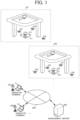
- FIG. 1 is a diagram illustrating a schematic configuration example of the remote monitoring system S.
- the drone Dn, the operator terminal Tm, and the management server MS are each connected to a communication network NW.
- the communication network NW includes, for example, the Internet, a mobile communication network, a radio base station thereof, and the like.
- the drone Dn is an example of an unmanned flying object, and is also referred to as a multicopter, or an UAV (Unmanned Aerial Vehicle).
- the drone Dn is capable of taking off according to takeoff instructions from a GCS (Ground Control Station) and flying autonomously.
- the drone Dn is used for, for example, delivery, surveying, photographing, monitoring, and the like.
- the GCS is installed as an application in the operator terminal Tm, for example, and is configured to be cooperated with the management server MS.
- the drone Dn can also fly according to remote control from the ground using a pilot (control) terminal installing the GCS.
- a port Pm used for takeoff and landing of drone Dn and a base instrument Em (an example of an instrument, a device, or an equipment) used for monitoring drone Dn are installed.
- a base staff manually performs a pre-flight inspection (e.g., checking vehicle status or condition) of the drone Dn (hereinafter, the inspection is referred to as "manual inspection").
- the base staff visually inspects a predetermined portion of the drone Dn for each inspection item of the manual inspection, or inspects the predetermined portion of the drone Dn by touching it.
- manual inspection result information (an example of base information) indicating the result of the manual inspection by the base staff is transmitted to the management server MS via the communication network NW from a terminal (an example of an instrument) such as a smartphone of the base staff.
- a terminal an example of an instrument
- the drone Dn which has completed the pre-flight inspection, is placed at the port Pm and takes off (departs) from the port Pm according to a predetermined schedule.
- the drone Dn that has returned to the drone base Bm lands at the port Pm.
- a plurality of ports Pm may be installed at one drone base Bm.
- the base instrument Em is connected to the communication network NW, is equipped with a base camera (e.g., an RGB camera or an infrared camera) for monitoring the drone Dn.
- the base instrument Em stores a base ID (identification information) for identifying the drone base Bm.
- the base camera is configured to sequentially (continuously) capture (image) drone Dn placed, for example, at the port Pm or an inspection place.
- Base image information (an example of base information) representing images (still images or moving images) captured by the base camera is transmitted from the base instrument Em to the management server MS together with the base ID.
- a plurality of base instruments Em may be installed at one drone base Bm.
- the base instrument Em may be provided with a wind sensor that detects (measures) at least one of wind speed and wind direction. Measurement information (an example of base information) measured by the wind sensor is transmitted from the base instrument Em to the management server MS. Furthermore, the base instrument Em may be provided with at least one of a temperature sensor, a humidity sensor, a rainfall (snow) amount sensor, and an air pressure sensor (aerotonometer). Measurement information (an example of base information) measured by these sensors is transmitted from the base instrument Em to the management server MS.
- the operator terminal Tm is a terminal used by an operator OPm who remotely monitors the plurality of drones Dn.
- the operator OP1 monitors the drones D1 to D4 that he/she is in charge of while looking at information displayed on a screen (a user interface screen) of the operator terminal T1.
- Such monitoring includes, for example, at least one of (i) checking the status of the pre-flight inspection of each of the plurality of drones Dn, (ii) monitoring the condition of each of the plurality of drones Dn before flight, (iii) monitoring the condition of each of the plurality of drones Dn in flight.
- Gaze timing In other words, gaze required timing
- the specific portion hereinafter referred to as “gaze portion”
- the gaze portion is a portion on the screen at which the operator OPm is requested to gaze. Examples of the gaze portion include a character string, an item, a tab, and an image (video) and the like. The gaze portion is highlighted on the screen.
- the highlighting includes displaying in a conspicuous (prominent) display manner (e.g., display color, display size, display mode, etc.).
- the gaze timing may be a time point, or may have a certain length of time (time width). Examples of the gaze timing include a time when drone Dn takes off or when drone Dn lands.
- the management server MS is composed of one or a plurality of server computers that manages information on the drone base Bm for each drone base Bm.
- the information relating to the drone base Bm includes, for example, information on the drone Dn under the jurisdiction of the drone base Bm, information on the operator OPm who monitors the drone Dn, and information on the operator terminal Tm used by the operator OPm.
- the management server MS identifies the plurality of drones Dn for which the operator OPm who has logged in by operating the operator terminal Tm is in charge, and controls to displays a list (hereinafter referred to as "drone list") showing the identified plurality of drones Dn on the operator terminal Tm of the operator OPm.
- the management server MS regularly or irregularly receives weather information at the drone base Bm from a weather management server (not shown) via the communication network NW.
- the weather information indicates the weather (fine, rain, snow, cloudy, etc.) at the drone base Bm.
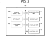
- FIG. 2 is a diagram illustrating a schematic configuration example of the drone Dn.
- the drone Dn includes a power supply unit 11, a drive unit 12, a positioning unit 13, a communication unit 14, a sensor unit 15, a storage unit 16, a control unit 17, and the like.
- the drone Dn includes a propeller (a rotor), which is a horizontal rotary wing, an arm pipe (including an arm joint) for attaching the propeller to a drone main body (a housing), and the like.
- the drone Dn includes a holding mechanism or the like for holding the article.
- the power supply unit 11 includes a detachable battery (an electric storage device) and the like.
- the power supply unit 11 supplies (supplies electricity) power stored in the battery to each unit of the drone Dn. Moreover, the power supply unit 11 sequentially measures a remaining battery capacity. Battery information indicating the remaining battery capacity measured by the power supply unit 11 is output to the control unit 17.
- the drive unit 12 includes a motor, a rotation shaft, and the like. The drive unit 12 rotates the plurality of rotors by a motor, a rotation shaft, and the like that are driven in accordance with a control signal output from the control unit 17.
- the positioning satellites may include satellites used by a plurality of satellite positioning systems, such as GPS (Global Positioning System) satellites, Michibiki (QZSS: Quasi-Zenith Satellite System) satellites, and Galileo satellites.
- Position information indicating the current position detected by the positioning unit 13 is sequentially output to the control unit 17.
- capture number (satellite capture number) information indicating the number (hereinafter referred to as "capture number") of positioning satellites captured by the positioning unit 13 is sequentially output to the control unit 17.
- the positioning unit 13 may detect the altitude of the drone Dn by the altitude sensor.
- the position information indicating the current position of the drone Dn includes altitude information indicating the altitude detected by the altitude sensor.
- the communication unit 14 has an antenna and a wireless communication function, and is responsible for controlling communication performed via the communication network NW.
- the direction of the vehicle camera (e.g., forward or downward of the drone Dn) can be controlled by the control unit 17.
- Sensing information sensed by the sensor unit 15 is output to the control unit 17.
- the storage unit 16 includes a nonvolatile memory or the like, and stores various programs and data. Moreover, the storage unit 16 stores a vehicle ID (identification information) for identifying the drone Dn.
- the position information (i.e., the position information from the positioning unit 13) of the drone Dn, vehicle image information (an example of vehicle information) representing images (still images or moving images (video)) captured by the vehicle camera, the battery information (an example of vehicle information) from the power supply unit 11, and the capture number information (an example of vehicle information) from the positioning unit 13 are transmitted to the management server MS via the communication network NW together with the vehicle ID of the drone Dn.
- the communication unit 22 controls communication performed via the communication network NW.
- the storage unit 23 includes a non-volatile memory or the like, and stores various programs (program code groups) and pieces of data.
- the various programs include an operating system (OS), a monitoring application, the GCS, and a web browser.
- the monitoring application is mainly a program for acquiring and displaying the drone list indicating the plurality of drones Dn for which the operator OPm is in charge from the management server MS.
- the monitoring application may be downloaded from a predetermined server to the operator terminal Tm.
- the control unit 24 (an example of a computer) includes at least one CPU, a ROM, an RAM, and the like, and executes processing according to the monitoring application stored in the ROM (or, the storage unit 23).
- the control unit 24 displays a login screen on the display.
- the control unit 24 transmits a login request including the user ID and the password to the management server MS via the communication unit 22 and the communication network NW.
- the user ID is identification information for identifying the operator OPm.
- the control unit 24 displays a drone monitoring screen including the drone list on the display.
- the plurality of drones Dn indicated in the drone list may be under the jurisdiction of the same drone base Bm, or may be under the jurisdiction of different drone bases Bm.
- the drone list indicates the drones Dn (e.g., the drones D1 to D4 and drones D5 to D9) belonging to each of the plurality of drone bases Bm (e.g., the drone base B1 and drone base B2).
- the display control data may be data of a web page displayed by the web browser.
- the display control data of the drone monitoring screen may be incorporated into the monitoring application.
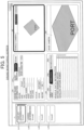
- FIGS. 4 and 5 are a diagram illustrating a display example of the drone monitoring screen displayed on the operator terminal T1 of the operator OP1.
- a drone list L indicating (showing) the drones D1 to D4 under the jurisdiction of the drone base B1 are displayed on the drone monitoring screen.
- a drone basic information display area A1 a drone detailed information display area A2, a vehicle camera (drone camera) display area A3, and a base camera display area A4 and the like are provided on the drone monitoring screen.
- the drone list L includes simple information display areas LA1 to LA4 corresponding to each of the drones D1 to D4 for which the operator OP1 is in charge.
- the simple information display areas LA1 to LA4 are scrollable.
- the names (drone names) of the drones D1 to D4 are displayed.
- the drone list L may include simple information display areas corresponding to each of the drones D5 to D9 for which the operator OP1 is in charge.
- the simple information display areas LA1 to LA4 are selectable by the operator OP1.
- the drone D1 to D4 can be selected via the simple information display areas LA1 to LA4.
- monitoring information obtained from the management server MS as appropriate for monitoring the drone D1 in the selected state is displayed in the drone basic information display area A1, the drone detailed information display area A2, the vehicle camera display area A3, and the base camera display area A4.
- the monitoring information includes, for example, the manual inspection result information, the base image information, vehicle data information, the vehicle image information, the weather information, and the like.
- the drone D1 is placed in the port P1 for take-off at the drone base B1 and is in a state where it is waiting for the take-off decision by the operator OP1.
- the drone D1 is in a state of flying (rising) above the port P1.
- the basic information of the drone D1, the status of the drone D1, the phase of the drone D1, the schedule of the drone D1, the weather information of the drone base B1, and a take-off decision button B are displayed in the drone basic information display area A1.
- the measurement information measured by the sensor provided with the base instrument Em may be displayed in the drone basic information display area A1.
- the basic information of the drone D1 includes, for example, drone name, type, model number, manufacturer (maker), base name (name of the drone base B1), and port name (name of port P1) of the drone D1, but is not particularly limited.
- the status (hereinafter referred to as "drone status") of the drone D1 indicates what kind of status the drone D1 is.
- the drone status is "JUST BEFORE TAKE-OFF", while in the display example of FIG. 5 , the drone status is "IN FLIGHT".
- Such drone status includes, for example, staying (waiting) on the ground, before flight (before take-off), dropping of delivered article, just before landing, in (during) return, error occurrence, etc., in addition to just before take-off and in flight.
- the error occurrence is, for example, the drone status when some abnormality is detected by the automatic inspection by the drone Dn.
- the phase (hereinafter referred to as the "drone phase”) of drone D1 roughly indicates what kind of phase the drone D1 is.
- “DELIVERY PREPARATION”, “IN FLIGHT”, and “RETURN” are displayed, as the drone phase, in the phase display area A11.
- “DELIVERY PREPARATION” is displayed in the phase display area A11 of FIG. 4 .
- "IN FLIGHT” is displayed in the phase display area A11 of FIG. 5 .
- the display contents of the phase display area A11 are changed (switched) according to changing (switching) of the drone phase.
- the schedule of the drone D1 includes, for example, a scheduled time of at least one of take-off, flight, landing, return, and the like of the drone D1.
- a vehicle status check tab TB1 In the display examples of FIG. 4 , a vehicle status check tab TB1, a vehicle data tab TB2, and a weather status tab TB3 are provided in the drone detailed information display area A2.
- the vehicle status check tab TB1 is selected and displayed among the tabs TB1 to TB3, and therefore the vehicle status check information is displayed below the tabs TB1 to TB3.
- the vehicle status check tab TB1 When the drone status is just before take-off, the vehicle status check tab TB1 is automatically selected, and the vehicle status check information is displayed so as to urge gazing to the operator OP1.
- the displaying the vehicle status check information in this manner can also be called highlighting of the vehicle status check information. This allows the operator OP1 to grasp at a glance the gaze portion that requires gazing according to the current drone status of the drone D1.
- the vehicle status check information is based on the manual inspection result information described above.
- "OK” as displayed in association with the inspection item "LOOSENESS OF ARM JOINT" which is included in the vehicle status check information, indicates for example, that the result of this manual inspection (vehicle status check) is fine (good).
- the selection display is automatically changed (switched) from the vehicle status check tab TB1 to the vehicle data tab TB2.
- the tabs TB1 to TB3 can be manually selected by the operator OP1, and for example, when the weather status TB3 is selected, the weather information of the drone base B1 is displayed below the tabs TB1 to TB3.
- the moving image (hereinafter referred to as “vehicle camera image”) captured by the vehicle camera of the drone D1 is displayed in the vehicle camera display area A3.
- the moving image (hereinafter referred to as “base camera image”) captured by the base camera of the base instrument E1 is displayed in the base camera display area A4.
- the drone status is "JUST BEFORE TAKE-OFF", which corresponds to the gaze timing, and therefore the base camera image is highlighted as the gaze portion (i.e., the specific portion being urged to be gazed).
- the frame A41 of the base camera display area A4 is displayed in red (i.e., changing from in black to in red).
- the drone status is "JUST BEFORE TAKE-OFF"
- the operator OP1 selects (presses) the take-off decision button B in the drone basic information display area A1
- a take-off command is transmitted to the drone D1.
- the display of the drone status and the drone phase changes to "IN FLIGHT" as illustrated in Fig. 5
- the highlighting is changed from the base camera image to the vehicle camera image.
- the frame A31 of the vehicle camera display area A3 is displayed in red (i.e., changing from in black to in red).
- the control unit 33 (an example of a computer) includes at least one CPU, a ROM, an RAM, and the like, and performs various processes according to the programs (program code) stored in the storage unit 32 or the non-transitory computer readable memory.
- FIG. 7 is a diagram illustrating an example of functional blocks in the control unit 33.
- the monitoring information acquisition unit 33e acquires, as monitoring information from the base management database 321, the base image information, the measurement information, the weather information and the like which are associated with the base ID of the drone base Bm to which the drone Dn selected by the logged-in operator OPm belongs, among the drone bases Bm (for example, the plurality of the drone bases Bm) identified by the base identification unit 33b.
- the base information of the drone base Bm to which the plurality of the drones Dn i.e., the drones Dn for which the operator OPm is in charge
- the drone status determination unit 33f identifies the current drone status of the drone Dn selected by the logged-in operator OPm on the basis of the monitoring information acquired by the monitoring information acquisition unit 33e. Furthermore, even after identifying the current drone status of the drone Dn from the monitoring information, the drone status determination unit 33f may identify the current drone status of the drone Dn by referring to the drone management database 322 at intervals of a predetermined time (e.g., 1 second to 60 seconds). Then, the drone status determination unit 33f detects a change (e.g., switching from "just before take-off" to "in flight") of the current drone status of the drone Dn selected by the logged-in operator OPm.
- a predetermined time e.g., 1 second to 60 seconds
- the drone phase determination unit 33g identifies the current drone status of the drone Dn identifies the current drone phase of the drone Dn selected by the logged-in operator OPm on the basis of the monitoring information acquired by the monitoring information acquisition unit 33e. Furthermore, even after identifying the current drone phase of the drone Dn from the monitoring information, the drone phase determination unit 33g may identify the current drone phase of the drone Dn by referring to the drone management database 322 at intervals of a predetermined time. Then, the drone phase determination unit 33g detects a change (e.g., switching from "delivery preparation" to "in flight") of the current drone phase of the drone Dn selected by the logged-in operator OPm.
- a change e.g., switching from "delivery preparation" to "in flight
- the gaze portion identification unit 33h identifies the gaze portion at which the logged-in operator OPm is requested to gaze, based on the current drone status identified by the drone status determination unit 33f. For example, in a case where the drone status is "just before take-off", the vehicle status check information as illustrated in FIG. 4 is identified as the gaze portion. Moreover, in a case where the drone status is "just before take-off", the base camera image may be identified as the gaze portion. On the other hand, in a case where the drone status is "in flight” or "error occurrence”, the vehicle data information as illustrated in FIG. 5 is identified as the gaze portion.
- the vehicle camera image may be identified as the gaze portion.
- the orientation (direction) of the vehicle camera is preferably identified as downward.
- the vehicle camera image may be identified as the gaze portion.
- the orientation of the vehicle camera is preferably identified as forward.
- the gaze portion identification unit 33h may identify the gaze portion at which the logged-in operator OPm is requested to gaze, based on the current drone phase identified by the drone phase determining unit 33g. For example, in a case where the drone status is "delivery preparation", the base camera image as illustrated in FIG. 4 is identified as the gaze portion. On the other hand, in a case where the drone status is "in flight”, the vehicle camera image as illustrated in FIG. 5 is identified as the gaze portion. Incidentally, in a case where the drone phase is "return”, the base camera image and the vehicle camera image may not be identified as the gaze portion.
- the gaze portion identification unit 33h may identify, at intervals of a predetermined time, the gaze portion at which the logged-in operator OPm is requested to gaze, based on the current drone status or the drone phase of the drone Dn selected by the logged-in operator OPm.
- the monitoring information display control unit 33j transmits, to the operator terminal Tm of the logged-in operator OPm, a display control data for causing the monitoring information acquired by the monitoring information acquisition unit 33e to be displayed. As a result, the monitoring information is displayed on the drone monitoring screen of the operator terminal Tm, for example, as illustrated in FIG 4 .
- the monitoring information display control unit 33j transmits, to the operator terminal Tm of the logged-in operator OPm, a highlighting control data for causing the gaze portion identified by the gaze portion identification unit 33h to be highlighted on the drone monitoring screen.
- the highlighting control data may be transmitted to the operator terminal Tm together with the display control data for causing the monitoring information to be displayed.
- the monitoring information display control unit 33j may preferably transmit, to the operator terminal Tm of the operator OPm, a highlight display control data for causing the gaze portion identified at the gaze timing by the gaze portion identification unit 33h to be highlighted. This makes it possible to highlight the gaze portion at a necessary timing for the operator OPm. Therefore, the monitoring information display controller 33j can switch the highlighting of the gaze portion in response to detecting the change in the current drone status or the drone phase.
- FIG. 8 is a sequence diagram illustrating an example of monitoring information display processing executed by the operator terminal T1 (the control unit 24) and the management server MS (the control unit 33).
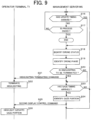
- FIG. 9 is a sequence diagram illustrating an example of highlighting update processing executed by the operator terminal T1 (the control unit 24) and the management server MS (the control unit 33).
- the drone Dn for which the operator OP1 (who uses operator terminal T1) is in charge will be taken as an example.
- the management server MS receives the login request from the operator terminal T1, the management server MS performs the login process by the login processing unit 33a in response to the login request (step S1).
- the login process it is determined whether a set of the user ID and the password included in the login request is registered in the operator management database 323. For example, when the set of the user ID and the password included in the login request is stored in the operator management database 323, it is determined that the set of the user ID and the password is registered, and the operator OP1 using the operator terminal T1 logs in.
- the management server MS identifies the plurality of drones Dn for which the logged-in operator OP1 is in charge (step S2). For example, in the operator management database 323, the drones Dn are identified by the vehicle ID associated with the user ID of the operator OP1.
- the management server MS identifies, by the base identification unit 33b, the drone base Bm to which the drone Dn belongs, for each drone Dn identified in step S2 (step S3).
- the drone base Bm is identified by the base ID associated with the vehicle ID of the drone Dn identified in step S2.
- the drone base Bm identified here may be one or multiple.
- the management server MS generates the drone list indicating the plurality of drones Dn identified in step S2 (step S4).
- the management server MS transmits, to the operator terminal T1 by the drone list display control unit 33c, a first display control command including the display control data for displaying the drone list generated in step S4 (step S5).
Landscapes
- Engineering & Computer Science (AREA)
- Aviation & Aerospace Engineering (AREA)
- Physics & Mathematics (AREA)
- General Physics & Mathematics (AREA)
- General Engineering & Computer Science (AREA)
- Theoretical Computer Science (AREA)
- Human Computer Interaction (AREA)
- Traffic Control Systems (AREA)
- Control Of Position, Course, Altitude, Or Attitude Of Moving Bodies (AREA)
Applications Claiming Priority (1)
| Application Number | Priority Date | Filing Date | Title |
|---|---|---|---|
| JP2023223104A JP7659041B1 (ja) | 2023-12-28 | 2023-12-28 | 情報処理装置、情報表示方法、及びプログラム |
Publications (1)
| Publication Number | Publication Date |
|---|---|
| EP4579631A1 true EP4579631A1 (de) | 2025-07-02 |
Family
ID=93852915
Family Applications (1)
| Application Number | Title | Priority Date | Filing Date |
|---|---|---|---|
| EP24219120.3A Pending EP4579631A1 (de) | 2023-12-28 | 2024-12-11 | Informationsverarbeitungsvorrichtung, informationsanzeigeverfahren und informationsverarbeitungsprogramm |
Country Status (4)
| Country | Link |
|---|---|
| US (1) | US20250217008A1 (de) |
| EP (1) | EP4579631A1 (de) |
| JP (1) | JP7659041B1 (de) |
| CN (1) | CN120236432A (de) |
Citations (4)
| Publication number | Priority date | Publication date | Assignee | Title |
|---|---|---|---|---|
| JP2019195173A (ja) | 2019-04-29 | 2019-11-07 | 株式会社センシンロボティクス | 飛行体の制御に関する情報表示方法 |
| JP2020536780A (ja) * | 2017-10-12 | 2020-12-17 | ザンベリ イマジニアリング ピーティーワイ リミテッド | ドローン着陸システムおよびドローン着陸ステーション |
| JP2023057120A (ja) * | 2019-04-29 | 2023-04-20 | 株式会社センシンロボティクス | 飛行体の制御に関する情報表示方法 |
| JP2023073018A (ja) * | 2021-11-15 | 2023-05-25 | ソニーグループ株式会社 | 装置及びシステム |
Family Cites Families (1)
| Publication number | Priority date | Publication date | Assignee | Title |
|---|---|---|---|---|
| JP6486744B2 (ja) | 2015-03-25 | 2019-03-20 | 株式会社日本総合研究所 | 地域監視サーバ、提供端末及びそのシステム |
-
2023
- 2023-12-28 JP JP2023223104A patent/JP7659041B1/ja active Active
-
2024
- 2024-11-14 CN CN202411622833.1A patent/CN120236432A/zh active Pending
- 2024-12-11 EP EP24219120.3A patent/EP4579631A1/de active Pending
- 2024-12-20 US US18/990,087 patent/US20250217008A1/en active Pending
Patent Citations (4)
| Publication number | Priority date | Publication date | Assignee | Title |
|---|---|---|---|---|
| JP2020536780A (ja) * | 2017-10-12 | 2020-12-17 | ザンベリ イマジニアリング ピーティーワイ リミテッド | ドローン着陸システムおよびドローン着陸ステーション |
| JP2019195173A (ja) | 2019-04-29 | 2019-11-07 | 株式会社センシンロボティクス | 飛行体の制御に関する情報表示方法 |
| JP2023057120A (ja) * | 2019-04-29 | 2023-04-20 | 株式会社センシンロボティクス | 飛行体の制御に関する情報表示方法 |
| JP2023073018A (ja) * | 2021-11-15 | 2023-05-25 | ソニーグループ株式会社 | 装置及びシステム |
Also Published As
| Publication number | Publication date |
|---|---|
| JP7659041B1 (ja) | 2025-04-08 |
| JP2025104920A (ja) | 2025-07-10 |
| US20250217008A1 (en) | 2025-07-03 |
| CN120236432A (zh) | 2025-07-01 |
Similar Documents
| Publication | Publication Date | Title |
|---|---|---|
| US10181211B2 (en) | Method and apparatus of prompting position of aerial vehicle | |
| JP7027599B2 (ja) | 収容設備管理装置及び収容設備管理方法 | |
| US10736154B2 (en) | Wireless real-time data-link sensor method and system for small UAVs | |
| CN108496130A (zh) | 飞行控制方法、设备、控制终端及其控制方法、无人机 | |
| CN112805650A (zh) | 无人机控制方法、装置及计算机可读存储介质 | |
| EP4579631A1 (de) | Informationsverarbeitungsvorrichtung, informationsanzeigeverfahren und informationsverarbeitungsprogramm | |
| KR20190048688A (ko) | 드론을 이용한 자율 비행 시스템 및 방법 | |
| US20250308241A1 (en) | Information processing device, information display method, and non-transitory computer readable memory | |
| JP7749053B1 (ja) | 情報処理装置、制御方法、及びプログラム | |
| US20250333163A1 (en) | Information processing device, display control method, and non-transitory computer readable memory | |
| CN111542793B (zh) | 无人机降落伞降落方法及系统 | |
| JP6903500B2 (ja) | 農業支援システム | |
| CN114822085B (zh) | 飞行管理装置和飞行管理方法 | |
| JP7744465B1 (ja) | 情報処理装置、及び情報処理方法 | |
| EP4492360A1 (de) | Informationsverarbeitungsvorrichtung und anzeigesteuerungsverfahren | |
| CN111279399B (zh) | 可飞行设备及其控制方法、系统和计算机可读存储介质 | |
| US20250299548A1 (en) | Information processing device, display control method, and non-transitory computer readable memory | |
| US20250076901A1 (en) | Information processing device, unmanned aerial vehicle, and method for detecting airframe orientation | |
| TWI744593B (zh) | 定翼機操作系統及其方法 | |
| JP7470773B1 (ja) | 情報処理装置、情報処理方法、及びプログラム | |
| KR102763204B1 (ko) | 이착륙 신호 발생 모듈 및 이를 활용한 드론 이착륙 신호생성 및 사용 방법 | |
| EP4201820B1 (de) | Informationsverarbeitungssystem, verfahren zur festlegung der freigabestelle und programm | |
| JP2025029872A (ja) | システム | |
| KR20230126649A (ko) | 드론 제어 방법 및 그 장치 | |
| CN118107819A (zh) | 一种应用于飞行器的智能辅助监控装置及其监控方法 |
Legal Events
| Date | Code | Title | Description |
|---|---|---|---|
| PUAI | Public reference made under article 153(3) epc to a published international application that has entered the european phase |
Free format text: ORIGINAL CODE: 0009012 |
|
| STAA | Information on the status of an ep patent application or granted ep patent |
Free format text: STATUS: REQUEST FOR EXAMINATION WAS MADE |
|
| 17P | Request for examination filed |
Effective date: 20241211 |
|
| AK | Designated contracting states |
Kind code of ref document: A1 Designated state(s): AL AT BE BG CH CY CZ DE DK EE ES FI FR GB GR HR HU IE IS IT LI LT LU LV MC ME MK MT NL NO PL PT RO RS SE SI SK SM TR |