EP4579321A1 - Motor, kameramodul und elektronische vorrichtung - Google Patents
Motor, kameramodul und elektronische vorrichtung Download PDFInfo
- Publication number
- EP4579321A1 EP4579321A1 EP24756066.7A EP24756066A EP4579321A1 EP 4579321 A1 EP4579321 A1 EP 4579321A1 EP 24756066 A EP24756066 A EP 24756066A EP 4579321 A1 EP4579321 A1 EP 4579321A1
- Authority
- EP
- European Patent Office
- Prior art keywords
- focus
- carrier
- image stabilization
- circuit board
- motor
- Prior art date
- Legal status (The legal status is an assumption and is not a legal conclusion. Google has not performed a legal analysis and makes no representation as to the accuracy of the status listed.)
- Pending
Links
Images


Classifications
-
- H—ELECTRICITY
- H04—ELECTRIC COMMUNICATION TECHNIQUE
- H04M—TELEPHONIC COMMUNICATION
- H04M1/00—Substation equipment, e.g. for use by subscribers
- H04M1/02—Constructional features of telephone sets
- H04M1/0202—Portable telephone sets, e.g. cordless phones, mobile phones or bar type handsets
- H04M1/026—Details of the structure or mounting of specific components
- H04M1/0264—Details of the structure or mounting of specific components for a camera module assembly
-
- G—PHYSICS
- G02—OPTICS
- G02B—OPTICAL ELEMENTS, SYSTEMS OR APPARATUS
- G02B27/00—Optical systems or apparatus not provided for by any of the groups G02B1/00 - G02B26/00, G02B30/00
- G02B27/64—Imaging systems using optical elements for stabilisation of the lateral and angular position of the image
- G02B27/646—Imaging systems using optical elements for stabilisation of the lateral and angular position of the image compensating for small deviations, e.g. due to vibration or shake
-
- G—PHYSICS
- G02—OPTICS
- G02B—OPTICAL ELEMENTS, SYSTEMS OR APPARATUS
- G02B7/00—Mountings, adjusting means, or light-tight connections, for optical elements
- G02B7/02—Mountings, adjusting means, or light-tight connections, for optical elements for lenses
- G02B7/04—Mountings, adjusting means, or light-tight connections, for optical elements for lenses with mechanism for focusing or varying magnification
- G02B7/08—Mountings, adjusting means, or light-tight connections, for optical elements for lenses with mechanism for focusing or varying magnification adapted to co-operate with a remote control mechanism
-
- G—PHYSICS
- G02—OPTICS
- G02B—OPTICAL ELEMENTS, SYSTEMS OR APPARATUS
- G02B7/00—Mountings, adjusting means, or light-tight connections, for optical elements
- G02B7/02—Mountings, adjusting means, or light-tight connections, for optical elements for lenses
- G02B7/04—Mountings, adjusting means, or light-tight connections, for optical elements for lenses with mechanism for focusing or varying magnification
- G02B7/09—Mountings, adjusting means, or light-tight connections, for optical elements for lenses with mechanism for focusing or varying magnification adapted for automatic focusing or varying magnification
-
- G—PHYSICS
- G03—PHOTOGRAPHY; CINEMATOGRAPHY; ANALOGOUS TECHNIQUES USING WAVES OTHER THAN OPTICAL WAVES; ELECTROGRAPHY; HOLOGRAPHY
- G03B—APPARATUS OR ARRANGEMENTS FOR TAKING PHOTOGRAPHS OR FOR PROJECTING OR VIEWING THEM; APPARATUS OR ARRANGEMENTS EMPLOYING ANALOGOUS TECHNIQUES USING WAVES OTHER THAN OPTICAL WAVES; ACCESSORIES THEREFOR
- G03B13/00—Viewfinders; Focusing aids for cameras; Means for focusing for cameras; Autofocus systems for cameras
- G03B13/32—Means for focusing
- G03B13/34—Power focusing
- G03B13/36—Autofocus systems
-
- G—PHYSICS
- G03—PHOTOGRAPHY; CINEMATOGRAPHY; ANALOGOUS TECHNIQUES USING WAVES OTHER THAN OPTICAL WAVES; ELECTROGRAPHY; HOLOGRAPHY
- G03B—APPARATUS OR ARRANGEMENTS FOR TAKING PHOTOGRAPHS OR FOR PROJECTING OR VIEWING THEM; APPARATUS OR ARRANGEMENTS EMPLOYING ANALOGOUS TECHNIQUES USING WAVES OTHER THAN OPTICAL WAVES; ACCESSORIES THEREFOR
- G03B3/00—Focusing arrangements of general interest for cameras, projectors or printers
- G03B3/10—Power-operated focusing
-
- G—PHYSICS
- G03—PHOTOGRAPHY; CINEMATOGRAPHY; ANALOGOUS TECHNIQUES USING WAVES OTHER THAN OPTICAL WAVES; ELECTROGRAPHY; HOLOGRAPHY
- G03B—APPARATUS OR ARRANGEMENTS FOR TAKING PHOTOGRAPHS OR FOR PROJECTING OR VIEWING THEM; APPARATUS OR ARRANGEMENTS EMPLOYING ANALOGOUS TECHNIQUES USING WAVES OTHER THAN OPTICAL WAVES; ACCESSORIES THEREFOR
- G03B30/00—Camera modules comprising integrated lens units and imaging units, specially adapted for being embedded in other devices, e.g. mobile phones or vehicles
-
- G—PHYSICS
- G03—PHOTOGRAPHY; CINEMATOGRAPHY; ANALOGOUS TECHNIQUES USING WAVES OTHER THAN OPTICAL WAVES; ELECTROGRAPHY; HOLOGRAPHY
- G03B—APPARATUS OR ARRANGEMENTS FOR TAKING PHOTOGRAPHS OR FOR PROJECTING OR VIEWING THEM; APPARATUS OR ARRANGEMENTS EMPLOYING ANALOGOUS TECHNIQUES USING WAVES OTHER THAN OPTICAL WAVES; ACCESSORIES THEREFOR
- G03B5/00—Adjustment of optical system relative to image or object surface other than for focusing
-
- H—ELECTRICITY
- H02—GENERATION; CONVERSION OR DISTRIBUTION OF ELECTRIC POWER
- H02K—DYNAMO-ELECTRIC MACHINES
- H02K41/00—Propulsion systems in which a rigid body is moved along a path due to dynamo-electric interaction between the body and a magnetic field travelling along the path
- H02K41/02—Linear motors; Sectional motors
- H02K41/035—DC motors; Unipolar motors
- H02K41/0352—Unipolar motors
- H02K41/0354—Lorentz force motors, e.g. voice coil motors
- H02K41/0356—Lorentz force motors, e.g. voice coil motors moving along a straight path
-
- G—PHYSICS
- G03—PHOTOGRAPHY; CINEMATOGRAPHY; ANALOGOUS TECHNIQUES USING WAVES OTHER THAN OPTICAL WAVES; ELECTROGRAPHY; HOLOGRAPHY
- G03B—APPARATUS OR ARRANGEMENTS FOR TAKING PHOTOGRAPHS OR FOR PROJECTING OR VIEWING THEM; APPARATUS OR ARRANGEMENTS EMPLOYING ANALOGOUS TECHNIQUES USING WAVES OTHER THAN OPTICAL WAVES; ACCESSORIES THEREFOR
- G03B2205/00—Adjustment of optical system relative to image or object surface other than for focusing
- G03B2205/0007—Movement of one or more optical elements for control of motion blur
-
- G—PHYSICS
- G03—PHOTOGRAPHY; CINEMATOGRAPHY; ANALOGOUS TECHNIQUES USING WAVES OTHER THAN OPTICAL WAVES; ELECTROGRAPHY; HOLOGRAPHY
- G03B—APPARATUS OR ARRANGEMENTS FOR TAKING PHOTOGRAPHS OR FOR PROJECTING OR VIEWING THEM; APPARATUS OR ARRANGEMENTS EMPLOYING ANALOGOUS TECHNIQUES USING WAVES OTHER THAN OPTICAL WAVES; ACCESSORIES THEREFOR
- G03B2205/00—Adjustment of optical system relative to image or object surface other than for focusing
- G03B2205/0053—Driving means for the movement of one or more optical element
- G03B2205/0069—Driving means for the movement of one or more optical element using electromagnetic actuators, e.g. voice coils
Definitions
- This application relates to the field of camera technologies, and in particular, to a motor, a camera module, and an electronic device.
- a conventional camera module includes an image stabilization motor and a focus motor.
- the image stabilization motor is located on an inner side of the focus motor.
- the focus motor needs to drive structures such as the image stabilization motor, a lens, and a variable aperture to move in an optical axis direction.
- a weight of a moving component formed by the focus motor, the image stabilization motor, the lens, the variable aperture, and the like is relatively heavy, which easily causes the moving component to overturn and have relatively poor reliability.
- Embodiments of this application provide a motor, a camera module including the motor, and an electronic device including the camera module, to obtain a motor and a camera module with a moving component that is not easy to overturn and has better reliability.
- a motor includes a base, an image stabilization carrier, a focus carrier, an image stabilization drive mechanism, and a focus drive mechanism.
- the image stabilization carrier is movably connected to the base, the focus carrier is located on an inner side of the image stabilization carrier, the focus carrier is movably connected to the image stabilization carrier, and the focus carrier is configured to mount a lens.
- the image stabilization drive mechanism is configured to drive the image stabilization carrier and the focus carrier to move in a first direction and/or a second direction relative to the base, and the focus drive mechanism is configured to drive the focus carrier to move in a third direction relative to the image stabilization carrier.
- the first direction intersects the second direction, and the third direction is perpendicular to the first direction and the second direction.
- the image stabilization carrier is located on an inner side of the focus carrier.
- the focus carrier needs to drive the image stabilization carrier, the lens, and the variable aperture to move in an optical axis direction.
- a weight of a moving component formed by the focus carrier, the image stabilization carrier, the lens, and the variable aperture is relatively heavy, and therefore, the focus drive mechanism needs to increase a driving force by increasing a volume. Therefore, such a setting is not conducive to a light-weight and miniaturized design of the motor.
- the focus carrier is disposed on the inner side of the image stabilization carrier.
- the focus carrier needs to drive the lens and the variable aperture to move in a Z-axis direction.
- the image stabilization carrier may be not needed for a moving component in a focusing process, that is, a weight of a moving component formed by the focus carrier, the lens, and the variable aperture is relatively light, thereby facilitating miniaturization of the focus drive mechanism.
- the motor in this embodiment can implement a light-weight and miniaturized setting.
- a distance between a connection position between the focus carrier and the image stabilization carrier and the center of gravity of the moving component formed by the focus carrier, the lens, and the variable aperture is relatively short, which helps reduce a risk of overturning the moving component.
- the image stabilization carrier needs at least two image stabilization drive mechanisms to push the image stabilization carrier to move on a plane perpendicular to the optical axis direction.
- the at least two sets of circuits need to pass through the focus carrier. Therefore, an energizing setting in this solution is relatively complex, and difficulty in disposing the motor is increased.
- the focus carrier is disposed on the inner side of the image stabilization carrier.
- the motor also needs one set of circuit to provide a signal and supply power for the focus drive mechanism, that is, a quantity of sets of circuits passing through the image stabilization carrier is relatively small. Therefore, an energizing solution of the solution in this embodiment is relatively simple, and can reduce difficulty in disposing the motor to a relatively large extent.
- the focus carrier is disposed on the inner side of the image stabilization carrier, so that the focus coil and the focus magnetic member can be arranged closer to the lens. In this way, when the focus coil and the focus magnetic member are vertically arranged, the focus coil and the focus magnetic member may partially protrude from an upper surface of the motor. It may be understood that the protruding part may be disposed inside a camera decoration member, to better improve space utilization of the camera decoration member.
- the image stabilization carrier is frame-shaped, and the image stabilization carrier is disposed around the focus carrier.
- the focus drive mechanism includes a focus coil and a focus magnetic member, the focus coil is disposed on the image stabilization carrier, the focus magnetic member is disposed on the focus carrier, and the focus coil faces the focus magnetic member.
- the image stabilization carrier is provided with a through hole, and the through hole runs through an outer side surface and an inner side surface of the image stabilization carrier; and the motor includes a focus circuit board, the focus circuit board is fastened on the outer side surface of the image stabilization carrier, and the focus coil is fastened on the focus circuit board and at least partially located in the through hole.
- the focus coil is disposed in the through hole of the image stabilization carrier, so that structural space of the image stabilization carrier can be used to a relatively large extent, thereby facilitating miniaturization of the motor.
- the motor further includes a first focus magnetic conductive member, the first focus magnetic conductive member is fastened on a side that is of the focus circuit board and that is away from the focus coil, and the first focus magnetic conductive member is disposed opposite to the focus magnetic member.
- the focus carrier is matched more tightly with the image stabilization carrier under an action of the magnetic attraction force.
- the focus carrier may be further limited in some directions on the plane perpendicular to the optical axis direction, that is, movement or shaking of the focus carrier in these directions is avoided, thereby ensuring stability of the focus carrier.
- the motor further includes a second focus magnetic conductive member and a third focus magnetic conductive member, both the second focus magnetic conductive member and the third focus magnetic conductive member are fastened on the first focus magnetic conductive member, both the second focus magnetic conductive member and the third focus magnetic conductive member protrude relative to a front surface of the first focus magnetic conductive member, and the front surface of the first focus magnetic conductive member faces the focus circuit board; and the center of the focus magnetic member is located between the center of the second focus magnetic conductive member and the center of the third focus magnetic conductive member.
- a magnetic attraction force between the first focus magnetic conductive member and the focus magnetic member may enable the focus magnetic member to generate a first restoring force in a negative direction of the Z-axis
- a magnetic attraction force between the second focus magnetic conductive member and the focus magnetic member may enable the focus magnetic member to generate a second restoring force in the positive direction of the Z-axis.
- the first restoring force and the second restoring force may be approximately offset or completely offset. In this case, stability of the focus carrier in a process of moving in the positive direction of the Z-axis is better.
- the focus magnetic member moves from a first position to a third position.
- a magnetic attraction force between the first focus magnetic conductive member and the focus magnetic member may enable the focus magnetic member to generate a third restoring force in the positive direction of the Z-axis
- a magnetic attraction force between the third focus magnetic conductive member and the focus magnetic member may enable the focus magnetic member to generate a fourth restoring force in the negative direction of the Z-axis.
- the third restoring force and the fourth restoring force may be approximately offset or completely offset. In this case, stability of the focus carrier in a process of moving in the Z-axis direction is better.
- the focus carrier is slidably connected to the image stabilization carrier through a first sliding shaft and a second sliding shaft.
- the focus carrier and the image stabilization carrier in this embodiment may implement surface contact.
- the focus carrier slides in the Z-axis direction relative to the image stabilization carrier, it can be ensured that the focus carrier and the image stabilization carrier have better stability.
- a contact area between the focus carrier and the image stabilization carrier is relatively large, when the focus carrier or the image stabilization carrier generates pressure on the X-Y plane, the focus carrier or the image stabilization carrier is not easily deformed due to relatively large pressure, thereby improving reliability of the motor to a relatively large extent.
- contact positions between the focus carrier and the first sliding shaft include a first contact position and a second contact position, a contact position between the focus carrier and the second sliding shaft includes a third contact position, and the second contact position is disposed closer to a bottom surface of the base than the third contact position; and the first focus magnetic conductive member is disposed closer to the first sliding shaft than the second sliding shaft.
- the focus magnetic conductive member is disposed close to the first sliding shaft, so that a central position of a magnetic attraction force generated by the focus magnetic conductive member and the focus magnetic member is disposed close to the first sliding shaft.
- a vertical distance that is, an arm of force of the magnetic attraction force
- a moment of the magnetic attraction force increases.
- the moment of the magnetic attraction force is equal to a product of a magnitude of the magnetic attraction force and the arm of force of the magnetic attraction force.
- the first overturning axis is a connection line between a bottom boundary line of the second contact position and a bottom boundary line of the third contact position.
- the second overturning axis is a connection line between a top boundary line of the first contact position and a top boundary line of the third contact position.
- the motor further includes a first reinforcement plate and a second reinforcement plate, and the first reinforcement plate and the second reinforcement plate are respectively spliced on two sides of the first focus magnetic conductive member; and both the first reinforcement plate and the second reinforcement plate are fastened on the side that is of the focus circuit board and that is away from the focus coil.
- first reinforcement plate and the second reinforcement plate may be configured to improve structural strength of the focus magnetic conductive member.
- the motor includes a focus drive chip, and the focus drive chip is fastened on the focus circuit board; the motor includes a plurality of wiring terminals and a plurality of conductive spring pieces, the plurality of wiring terminals are fastened on the base at an interval, and the plurality of conductive spring pieces are fastened on the image stabilization carrier at an interval; and entry ends of the plurality of conductive spring pieces are electrically connected to a plurality of ports of the focus drive chip in a one-to-one correspondence through the focus circuit board, and exit ends of the plurality of conductive spring pieces are electrically connected to the plurality of wiring terminals in a one-to-one correspondence.
- the image stabilization carrier may move in any direction of the X-Y plane relative to the base, a distance between the image stabilization carrier and the base changes in an image stabilization process. Therefore, in this embodiment, the conductive spring piece with an elastic force is disposed to connect the wiring terminal of the base to the focus circuit board of the image stabilization carrier, so that when a distance between the image stabilization carrier and the base changes, stretching of the conductive spring piece is used to offset the distance change, to ensure that a circuit is not easily disconnected, that is, improve circuit stability.
- the motor includes a plurality of traces, the plurality of traces are embedded on the image stabilization carrier at an interval, and both an entry end and an exit end of each trace are exposed relative to the image stabilization carrier; and the entry ends of the plurality of conductive spring pieces are electrically connected to exit ends of the plurality of traces in a one-to-one correspondence, and the exit ends of the plurality of traces are electrically connected to the plurality of ports of the focus drive chip in a one-to-one correspondence through the focus circuit board.
- the plurality of conductive spring pieces may be electrically connected to the plurality of ports of the focus drive chip in a one-to-one correspondence through the exit ends of the plurality of traces, where the plurality of traces are embedded on the image stabilization carrier at an interval.
- a part of a circuit electrically connected between the wiring terminal and the focus drive chip may be embedded in the image stabilization carrier, so that a circuit outside the image stabilization carrier can be more concise.
- the motor includes a plurality of conductive springs, and the plurality of conductive springs are fastened on the focus carrier at an interval; and exit ends of the plurality of conductive springs are electrically connected to the plurality of conductive spring pieces in a one-to-one correspondence, and entry ends of the plurality of conductive springs are configured to be electrically connected to a plurality of ports of a drive chip of a variable aperture in a one-to-one correspondence.
- the motor further includes a second flexible circuit board, the second flexible circuit board is configured to electrically connect a plurality of ports of a drive chip of a variable aperture to the first flexible circuit board in a one-to-one correspondence through the focus circuit board.
- the focus carrier may move in the Z-axis direction relative to the image stabilization carrier, a distance between the focus carrier and the image stabilization carrier changes in a focusing process. Therefore, in this embodiment, the second flexible circuit board that is bendable is disposed, so that the variable aperture of the focus carrier is connected to the second flexible circuit board of the image stabilization carrier, so that when the distance between the focus carrier and the image stabilization carrier changes, bendable performance of the second flexible circuit board is used to offset the distance change, to ensure that a circuit is not easily disconnected, that is, improve circuit stability.
- the second flexible circuit board includes a first segment, a second segment, and a third segment, the second segment is connected between the first segment and the third segment, the first segment and the third segment are disposed opposite to each other, and the second segment is in a bent shape; and the first segment is configured to be electrically connected to the plurality of ports of the drive chip of the variable aperture, and the third segment is electrically connected to the first flexible circuit board through the focus circuit board.
- the second flexible circuit board is in a top-down bent and folded state, so that when the distance between the focus carrier and the image stabilization carrier changes, the bent and folded state of the second flexible circuit board is used to offset the distance change, to ensure that a circuit is not easily disconnected, that is, improve circuit stability.
- a very small motion reaction force of the second flexible circuit board may also be implemented.
- the focus circuit board, the first flexible circuit board, and the second flexible circuit board are of an integrally formed structure.
- the image stabilization carrier includes a first side portion and a third side portion that are disposed opposite to each other, and a second side portion and a fourth side portion that are disposed opposite to each other, and the second side portion and the fourth side portion are connected between the first side portion and the third side portion;
- first flexible circuit board may alternatively be located between the fourth side portion of the image stabilization carrier and the base, so that the first flexible circuit board is located in magnetic-free space, thereby reducing impact on a magnetic member on the motor.
- a camera module includes a lens, an image sensor, and the foregoing motor.
- the lens is mounted on the focus carrier, and the image sensor is located on a light exit side of the lens.
- the camera module further includes a variable aperture, and the variable aperture is located on a light entry side of the lens.
- an electronic device includes a device housing and the foregoing camera module, and the camera module is disposed in the device housing.
- connection may be a detachable connection, a nondetachable connection, a direct connection, or an indirect connection through an intermediate medium.
- a "fixed connection” means that two parts are connected to each other and a relative position relationship remains unchanged after the two parts are connected.
- Slideable connection means that two parties are connected to each other and can slide relative to each other after the two parties are connected to each other.
- orientation terms mentioned in embodiments of this application are merely directions based on the accompanying drawings. Therefore, the orientation terms are used to better and more clearly describe and understand embodiments of this application, instead of indicating or implying that a specified apparatus or element should have a specific orientation and be constructed and operated in a specific orientation. Therefore, this cannot be understood as a limitation on embodiments of this application.
- a plurality of means at least two.
- a and/or B include three solutions, which are specifically a solution A, a solution B, and a solution AB.
- first”, “second”, “third”, and “fourth” are merely intended for a purpose of description, and shall not be understood as an indication or implication of relative importance or an implicit indication of a quantity of indicated technical features. Therefore, a feature defined by “first”, “second”, “third”, or “fourth” may explicitly or implicitly include one or more of the features.
- a small deviation is allowed, which can be approximately parallel or vertical.
- a is parallel to B means that A is parallel or approximately parallel to B, and an included angle of 0 degrees to 10 degrees between A and B is allowed.
- a is vertical to B means that A is vertical or approximately vertical to B, and an included angle of 80 degrees to 100 degrees between A and B is allowed.
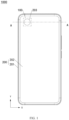
- FIG. 1 is a diagram of a structure of an electronic device 1000 according to an embodiment of this application.
- the electronic device 1000 may be a device with a camera function, such as a mobile phone, a tablet personal computer (tablet personal computer), a laptop computer (laptop computer), a personal digital assistant (personal digital assistant, PDA), a camera, a personal computer, a notebook computer, an in-vehicle device, a wearable device, augmented reality (augmented reality, AR) glasses, an AR helmet, virtual reality (virtual reality, VR) glasses, or a VR helmet.
- augmented reality augmented reality
- AR augmented reality
- VR virtual reality
- FIG. 2 is a partial sectional view of the electronic device 1000 shown in FIG. 1 at a line A-A according to an embodiment.
- the electronic device 1000 may include a camera module 100, a device housing 200, and a screen 300.
- the camera module 100 may be a rear-facing camera module, or may be a front-facing camera module.
- FIG. 1 and the following related accompanying drawings only schematically show some components included in the electronic device 1000. Actual shapes, actual sizes, actual positions, and actual structures of these components are not limited by FIG. 1 and the following accompanying drawings.
- the electronic device 1000 may not include the screen 300.
- a width direction of the electronic device 1000 is defined as an X-axis.
- a length direction of the electronic device 1000 is a Y-axis.
- a thickness direction of the electronic device 1000 is a Z-axis. It may be understood that a coordinate system of the electronic device 1000 may be flexibly set according to a specific actual requirement. In this embodiment, description is provided by using an example in which an X-axis direction is a first direction, a Y-axis direction is a second direction, and a Z-axis direction is a third direction.
- the device housing 200 may include a frame 201 and a rear cover 202.
- the rear cover 202 is fastened to the frame 201.
- the rear cover 202 may be fastened to the frame 201 by using adhesive.
- the rear cover 202 and the frame 201 may alternatively be of an integrally formed structure, that is, the rear cover 202 and the frame 201 are of one integral structure.
- the screen 300 may be located on a side that is of the frame 201 and that is away from the rear cover 202. In this case, the screen 300 and the rear cover 202 may be respectively located on two sides of the frame 201.
- the screen 300, the frame 201, and the rear cover 202 jointly enclose an interior of the electronic device 1000.
- the interior of the electronic device 1000 may be configured to place a component of the electronic device 1000, for example, a battery, a telephone receiver, or a microphone.
- the screen 300 may be a flat screen, or may be a curved screen.
- the camera module 100 may be located in the interior of the electronic device 1000.
- the camera module 100 may be located on a side that is of the screen 300 and that faces the rear cover 202.
- the rear cover 202 may be provided with a light transmission hole 203.
- a shape of the light transmission hole 203 is not limited to a circle shown in FIG. 1 .
- the light transmission hole 203 connects the interior of the electronic device 1000 to an exterior of the electronic device 1000. Light from the exterior of the electronic device 1000 may enter the interior of the electronic device 1000 through the light transmission hole 203.
- the camera module 100 may collect light that enters the interior of the electronic device 1000.
- the camera module 100 may be a common camera module (that is, an optical axis direction of the camera module 100 is the Z-axis direction).
- the camera module 100 may alternatively be a periscope camera module (that is, the optical axis direction of the camera module 100 is any direction on an X-Y plane). It may be understood that the camera module 100 in this embodiment is described by using an example of a common camera module.
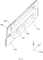
- FIG. 3 is a diagram of a structure of the camera module 100 shown in FIG. 1 according to an embodiment.
- FIG. 4 is a partial exploded diagram of the camera module 100 shown in FIG. 3 according to an embodiment.
- the camera module 100 may include a motor 1, a lens 2, a variable aperture 3, a module circuit board 4, an image sensor 5, a light filter holder 6, and a light filter 7. It may be understood that the image sensor 5 is also referred to as a light sensitive chip or a light sensitive element.
- the image sensor 5 is configured to collect ambient light, and convert image information carried in the ambient light into an electrical signal.
- an optical axis direction of the lens 2 is a same direction as an optical axis direction of the camera module 100.
- the optical axis direction of the camera module 100 an optical axis direction of the motor 1, and the optical axis direction of the lens 2 all are a same direction.
- the X-axis direction is defined as a width direction of the camera module 100
- the Y-axis direction is defined as a length direction of the camera module 100
- the Z-axis direction is defined as the optical axis direction of the camera module 100.
- a coordinate system of the camera module 100 may be flexibly set according to a specific actual requirement.
- variable aperture 3 may be located on a light entry side of the lens 2.
- the variable aperture 3 has an aperture hole 3a. A size of the aperture hole 3a may be automatically adjusted. Light may enter the lens 2 through the aperture hole 3a of the variable aperture 3.
- the image sensor 5 is fastened to the module circuit board 4, and is electrically connected to the module circuit board 4.
- signals may be mutually transmitted between the image sensor 5 and the module circuit board 4.
- the light filter holder 6 is fastened to the module circuit board 4.
- the light filter holder 6 and the image sensor 5 are located on a same side of the module circuit board 4.
- the light filter holder 6 is provided with a light transmission hole 6a.
- the light filter 7 is fastened to the light filter holder 6.
- the light filter 7 may be located in the light transmission hole 6a.
- the light filter 7 is further disposed opposite to the image sensor 5.
- the light filter 7 may be configured to filter infrared light, blue light, or the like in light before entering the image sensor 5, to ensure that the image sensor 5 has high imaging quality.
- the motor 1 is fastened on the module circuit board 4, and is located on a same side of the module circuit board 4 as the image sensor 5.
- the image sensor 5, the light filter 7, the lens 2, and the variable aperture 3 are sequentially arranged.
- the image sensor 5 is located on a light exit side of the lens 2.
- the light filter 7 is located between the lens 2 and the image sensor 5.
- the motor 1 is fastened on the module circuit board 4, so that stacking of the motor 1 and the light filter holder 6 in the Z-axis direction can be avoided, that is, the motor 1 and the light filter holder 6 may be disposed in a staggered manner on the X-Y plane, thereby reducing a height of the camera module 100 to a relatively large extent.
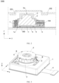
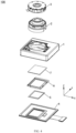
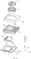
- FIG. 5 is a partial exploded diagram of the motor 1 shown in FIG. 4 according to an embodiment .
- the motor 1 includes an image stabilization drive module 10, a focus drive module 20, a limiting bracket 30, and a housing 40.
- the focus drive module 20 is disposed on the image stabilization drive module 10, so that the image stabilization drive module 10 and the focus drive module 20 form an integrated motor, namely, the motor 1.
- a volume of the motor 1 in this embodiment is smaller, and this helps implement miniaturization of the motor 1, thereby helping save internal space of the electronic device 1000.
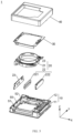
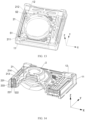
- FIG. 6 is a partial exploded view of the image stabilization drive module 10 shown in FIG. 5 according to an embodiment .
- the image stabilization drive module 10 includes a base 11, an image stabilization carrier 12, and an image stabilization drive mechanism 13.
- the image stabilization carrier 12 is movably connected to the base 11.
- the image stabilization carrier 12 may move in the X-axis direction and/or the Y-axis direction relative to the base 11.
- the base 11 may be fastened on the module circuit board 4 (referring to FIG. 4 ). In this case, a position of the base 11 relative to the module circuit board 4 remains unchanged.
- the base 11 may also be referred to as an image stabilization fixing component.
- the image stabilization carrier 12 is movably connected to the base 11, and the image stabilization carrier 12 may also be referred to as an image stabilization moving component.
- the image stabilization carrier 12 is frame-shaped.
- the image stabilization carrier 12 includes a first side portion 121 and a third side portion 123 that are disposed opposite to each other, and a second side portion 122 and a fourth side portion 124 that are disposed opposite to each other.
- the second side portion 122 and the fourth side portion 124 are connected between the first side portion 121 and the third side portion 123.
- the image stabilization drive mechanism 13 includes a first image stabilization coil 131, a first image stabilization magnetic member 132, a second image stabilization coil 133, and a second image stabilization magnetic member 134.
- the first image stabilization coil 131 is fastened on the base 11.
- the first image stabilization magnetic member 132 is fastened on the first side portion 121 of the image stabilization carrier 12.
- the first image stabilization coil 131 faces the first image stabilization magnetic member 132, and is configured to drive the image stabilization carrier 12 to move in the X-axis direction relative to the base 11.
- the second image stabilization coil 133 is fastened on the base 11.
- the second image stabilization magnetic member 134 is fastened on the second side portion 122.
- the second image stabilization coil 133 faces the second image stabilization magnetic member 134, and is configured to drive the image stabilization carrier 12 to move in the Y-axis direction relative to the base 11.
- the image stabilization drive mechanism 13 may alternatively be another drive mechanism. This is not specifically limited in this application.
- the image stabilization carrier 12 has a first sliding shaft 51 and a second sliding shaft 52.
- a first groove 53 and a second groove 54 may be disposed on the image stabilization carrier 12.
- the first sliding shaft 51 is then fastened in the first groove 53 through glue dispensing or welding, and a part of an outer surface of the first sliding shaft 51 is exposed relative to the first groove 53.
- the second sliding shaft 52 is fastened in the second groove 54 through glue dispensing or welding, and a part of an outer surface of the second sliding shaft 52 is exposed relative to the second groove 54.
- the first sliding shaft 51 and the second sliding shaft 52 each may alternatively be a part of the image stabilization carrier 12 being an integrated mechanical member.
- a through hole 55 is disposed on the third side portion 123 of the image stabilization carrier 12.
- the through hole 55 runs through an inner surface 56a and an outer surface 56b of the image stabilization carrier 12.
- the focus drive module 20 includes a focus carrier 21, a focus drive mechanism 22, and a circuit board assembly 23.
- the focus drive mechanism 22 includes a focus coil 221 and a focus magnetic member 222.
- the focus magnetic member 222 may be a magnet or another magnetic component.
- FIG. 7 is a partial exploded view of the circuit board assembly 23 shown in FIG. 5 according to an embodiment.
- the circuit board assembly 23 includes a focus circuit board 231, a focus drive chip 232, a focus magnetic conductive member 233, and a focus sensor 234.
- the circuit board assembly 23 may not include the focus magnetic conductive member 233 and the focus sensor 234.
- FIG. 8 is a partial diagram of a structure of the motor 1 shown in FIG. 4 according to an embodiment .
- FIG. 8 may be an assembly diagram of the circuit board assembly 23 and the focus coil 221 according to an embodiment .
- both the focus drive chip 232 and the focus sensor 234 are fastened on the focus circuit board 231, and are electrically connected to the focus circuit board 231.
- the focus coil 221 is fastened on the focus circuit board 231, and is electrically connected to the focus circuit board 231. It may be understood that an input terminal and an output terminal of the focus coil 221 may form a current loop with the focus drive chip 232 through the focus circuit board 231. In this case, the focus drive chip 232 may control a current status of the focus coil 221 (for example, whether a current is connected or a current value when the focus coil 221 is energized) through the focus circuit board 231.
- the focus coil 221 may be disposed around the focus drive chip 232 and the focus sensor 234.
- the focus drive chip 232 and the focus sensor 234 can effectively use inner space of the focus coil 221, thereby improving space utilization of the motor 1 to a relatively large extent.
- the focus coil 221 may alternatively be a part of the circuit board assembly 23. In this way, when the circuit board assembly 23 is sold as a selling unit, the focus coil 221 may also be sold as a part of the circuit board assembly 23.
- the focus magnetic conductive member 233 includes a first focus magnetic conductive member 2331, a second focus magnetic conductive member 2332, and a third focus magnetic conductive member 2333.
- the second focus magnetic conductive member 2332 and the third focus magnetic conductive member 2333 may be fastened to the first focus magnetic conductive member 2331 at an interval, and both protrude from one side of the first focus magnetic conductive member 2331.
- the second focus magnetic conductive member 2332 may be fastened to the first focus magnetic conductive member 2331 in a bending manner (a bending angle is not limited), or may be fastened to the first focus magnetic conductive member 2331 in a non-bending manner.
- the second focus magnetic conductive member 2332 and the first focus magnetic conductive member 2331 may be of an integrally formed structure.
- the second focus magnetic conductive member 2332 may alternatively be fastened to the first focus magnetic conductive member 2331 in a manner of bonding, welding, or the like.
- a manner of connecting the third focus magnetic conductive member 2333 and the first focus magnetic conductive member 2331 refer to a manner of connecting the second focus magnetic conductive member 2332 and the first focus magnetic conductive member 2331. Details are not described herein again.
- the second focus magnetic conductive member 2332 and the third focus magnetic conductive member 2333 may alternatively be fastened to the front surface 2334 of the first focus magnetic conductive member 2331 at an interval.
- the focus magnetic conductive member 233 may not include the second focus magnetic conductive member 2332 and the third focus magnetic conductive member 2333.
- the focus magnetic conductive member 233 is fastened on a side that is of the focus circuit board 231 and that is away from the focus coil 221.
- the front surface 2334 of the first focus magnetic conductive member 2331 is fastened to a surface that is of the focus circuit board 231 and that is away from the focus coil 221.
- FIG. 9 is a partial diagram of a structure of the motor 1 shown in FIG. 4 at different angles according to an embodiment.
- FIG. 9 may be an assembly diagram of the image stabilization carrier 12, the circuit board assembly 23, and the focus coil 221.
- the focus circuit board 231 is fastened on the image stabilization carrier 12.
- the focus coil 221 may be fastened on the image stabilization carrier 12 through the focus circuit board 231.
- the focus circuit board 231 is fastened on an outer side surface 56a of the image stabilization carrier 12, and is located on the third side portion 123 of the image stabilization carrier 12.
- the focus circuit board 231 is fastened on the outer side surface of the image stabilization carrier 12. At least a part of the focus coil 221 may be located in the through hole 55 of the image stabilization carrier 12. It may be understood that at least a part of the focus coil 221 is disposed in the through hole 55 of the image stabilization carrier 12, so that structural space of the image stabilization carrier 12 can be used to a relatively large extent, thereby facilitating miniaturization of the motor 1.
- a plane wound by a conducting wire of the focus coil 221 may be parallel to the optical axis direction.
- the focus coil 221 is vertically arranged, so that the focus coil 221 may occupy a relatively small area on the X-Y plane, thereby facilitating miniaturization of the motor 1.
- FIG. 10 is a partial diagram of a structure of the motor 1 shown in FIG. 4 according to an embodiment.
- FIG. 10 may be an assembly diagram of the base 11, the image stabilization carrier 12, the circuit board assembly 23, and the focus coil 221.
- the focus circuit board 231 when the focus circuit board 231 is fastened on the image stabilization carrier 12, the focus circuit board 231 may be located between the image stabilization carrier 12 and the base 11. It may be understood that, when the image stabilization carrier 12 moves in the X-Y plane relative to the base 11, the image stabilization carrier 12 may drive the circuit board assembly 23 and the focus coil 221 to move in the X-Y plane.
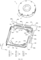
- FIG. 11 is a partial diagram of a structure of the focus drive module 20 shown in FIG. 5 according to an embodiment .
- FIG. 11 may be an assembly diagram of the focus carrier 21 and the focus magnetic member 222.
- the focus magnetic member 222 is fastened on the focus carrier 21.
- a polarity direction of the focus magnetic member 222 may be parallel to the optical axis direction.
- the focus magnetic member 222 may be arranged vertically, to reduce space occupied by the focus magnetic member 222 on the X-Y plane.
- the polarity direction of the focus magnetic member 222 may be a direction from a north pole of the focus magnetic member 222 to a south pole, or a direction from a south pole to a north pole.
- description is provided by using an example in which the direction from the north pole of the focus magnetic member 222 to the south pole is the polarity direction of the focus magnetic member 222.
- the focus magnetic member 222 may be fastened on the focus carrier 21 in a manner of using adhesive or the like.
- a groove may be disposed on the focus carrier 21. Then, the focus magnetic member 222 is disposed in the groove. In this way, a structure formed by the focus magnetic member 222 and the focus carrier 21 has relatively good integrity; and the focus magnetic member 222 may use structural space of the focus carrier 21, and the focus magnetic member 222 does not increase a size of the focus drive module to a relatively large extent.
- the focus magnetic member 222 may be embedded in the focus carrier 21 by using an injection molding processing process.
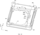
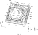
- FIG. 12 is a partial diagram of a structure of the motor 1 shown in FIG. 4 according to an embodiment .
- FIG. 13 is a diagram of a structure of a part of the motor 1 in FIG. 12 at another angle.
- FIG. 12 may be an assembly diagram of structures such as the focus carrier 21 and the image stabilization carrier 12.
- the focus carrier 21 is located on an inner side of the image stabilization carrier 12. It may be understood that when the focus carrier 21 is located on the inner side of the image stabilization carrier 12, the image stabilization carrier 12 may be disposed around the focus carrier 21.
- the image stabilization carrier 12 may be disposed around the focus carrier 21 by one circle, or a part of the image stabilization carrier 12 may be disposed around the focus carrier 21.
- the image stabilization carrier 12 is frame-shaped. In this case, the image stabilization carrier 12 is disposed around the focus carrier 21.
- the image stabilization carrier is located on an inner side of the focus carrier.
- the focus carrier needs to drive the image stabilization carrier, the lens, and the variable aperture to move in the Z-axis direction.
- a weight of a moving component formed by the focus carrier, the image stabilization carrier, the lens, and the variable aperture is relatively heavy, and therefore, the focus drive mechanism needs to increase a driving force by increasing a volume. Therefore, such a setting is not conducive to a light-weight and miniaturized design of the motor.
- the focus carrier 21 is disposed on the inner side of the image stabilization carrier 12.
- the focus carrier 21 needs to drive the lens 2 and the variable aperture 3 to move in the Z-axis direction.
- the image stabilization carrier may be not needed for the moving component in a focusing process, that is, a weight of a moving component formed by the focus carrier 21, the lens 2, and the variable aperture 3 is relatively light, thereby facilitating miniaturization of the focus drive mechanism 22.
- the motor 1 in this embodiment can implement a light-weight and miniaturized setting.
- a distance between a connection position between the focus carrier 21 and the image stabilization carrier and the center of gravity of the moving component formed by the focus carrier 21, the lens 2, and the variable aperture 3 is relatively short, which helps reduce a risk of overturning the moving component.
- the image stabilization carrier needs at least two image stabilization drive mechanisms to push the image stabilization carrier to move on the X-Y plane.
- the at least two sets of circuits need to pass through the focus carrier. Therefore, an energizing setting in this solution is relatively complex, and difficulty in disposing the motor is increased.
- the focus carrier 21 is disposed on the inner side of the image stabilization carrier 12.
- an energizing solution of the solution in this embodiment is relatively simple, and can reduce difficulty in disposing the motor 1 to a relatively large extent.
- the focus carrier 21 is disposed on the inner side of the image stabilization carrier 12, so that the focus coil and the focus magnetic member can be arranged closer to the lens. In this way, when the focus coil and the focus magnetic member are vertically arranged, the focus coil and the focus magnetic member may partially protrude from an upper surface of the motor 1. It may be understood that the protruding part may be disposed inside a camera decoration member, to better improve space utilization of the camera decoration member.
- the focus carrier 21 is slidably connected to the image stabilization carrier 12 in the Z-axis direction. In this way, the focus carrier 21 may move in the Z-axis direction relative to the image stabilization carrier 12, that is, the focus carrier 21 may move in the Z-axis direction relative to the base 11.
- the focus carrier 21 is slidably connected to the image stabilization carrier 12 in the Z-axis direction, so that when the image stabilization carrier 12 moves in the X-Y plane relative to the base 11, the image stabilization carrier 12 may also drive the focus carrier 21 to move in the X-Y plane relative to the base 11.
- the focus carrier 21 is slidably connected to the image stabilization carrier 12 in the Z-axis direction through the first sliding shaft 51 and the second sliding shaft 52.
- the focus carrier 21 and the image stabilization carrier 12 in this embodiment may implement surface contact.
- the focus carrier 21 slides in the Z-axis direction relative to the image stabilization carrier 12, it can be ensured that the focus carrier 21 and the image stabilization carrier 12 have better stability.
- a contact area between the focus carrier 21 and the image stabilization carrier 12 is relatively large, when the focus carrier 21 or the image stabilization carrier 12 generates pressure on the X-Y plane, the focus carrier 21 or the image stabilization carrier 12 is not easily deformed due to relatively large pressure, thereby improving reliability of the motor 1 to a relatively large extent.
- the focus carrier 21 may alternatively be connected to the image stabilization carrier 12 in the Z-axis direction in a manner of using a ball.
- the focus carrier 21 is provided with a first sliding slot 211 and a second sliding slot 212 that are disposed at an interval.
- a part of the first sliding shaft 51 is disposed in the first sliding slot 211.
- a part of the second sliding shaft 52 is disposed in the second sliding slot 212.
- the first sliding shaft 51 may be tightly matched with the focus carrier 21.
- the second sliding shaft 52 may be loosely matched with the focus carrier 21.
- the first sliding slot 211 is set to be in a "V" shape.
- the second sliding slot 212 is in an "L” shape, a "U” shape, or the like. In this way, the first sliding shaft 51 is wrapped by using the first sliding slot 211 in the "V" shape. It may be understood that, the first sliding shaft 51 is tightly matched with the focus carrier 21, and the second sliding shaft 52 is loosely matched with the focus carrier 21, so that difficulty in assembling the focus carrier 21 and the image stabilization carrier 12 can be reduced.
- the focus carrier 21 may alternatively be connected to the first sliding shaft 51 and the second sliding shaft 52 in another manner.
- a first via hole and a second via hole are disposed on the focus carrier 21. Then, the first sliding shaft 51 and the second sliding shaft 52 are respectively sleeved on the first via hole and the second via hole.
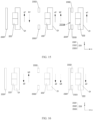
- FIG. 14 is a partial sectional view of the camera module 100 shown in FIG. 3 at a line B-B according to an embodiment.
- FIG. 15 is a simplified diagram of a force applied to the focus magnetic conductive member 233, the focus magnetic member 222, and the focus carrier 21 that are shown in FIG. 14 and that move in the positive direction of the Z-axis.
- the focus magnetic conductive member 233 includes a first focus magnetic conductive member 2331, a second focus magnetic conductive member 2332, and a third focus magnetic conductive member 2333.
- the second focus magnetic conductive member 2332 and the third focus magnetic conductive member 2333 are disposed on the first focus magnetic conductive member 2331 at an interval, and both protrude from a front surface 2334 of the first focus magnetic conductive member 2331.
- the center of the focus magnetic member 222 is located between the center of the second focus magnetic conductive member 2332 and the center of the third focus magnetic conductive member 2333.
- FIG. 20 is a diagram of a structure of the base 11 shown in FIG. 6 at different angles according to an embodiment.
- the base 11 is provided with a plurality of wiring terminals 50.
- the wiring terminals 50 include a first wiring terminal 56, a second wiring terminal 57, a third wiring terminal 58, and a fourth wiring terminal 59.
- the third wiring terminal 58 may be embedded in the second corner portion 29b of the base 11, and is disposed at an interval from the second wiring terminal 57.
- An entry end 581 of the third wiring terminal 58 may be exposed relative to the top surface of the second corner portion 29b, and is disposed at an interval from the entry end 571 of the second wiring terminal 57.
- An exit end 582 of the third wiring terminal 58 may be exposed relative to the bottom surface of the second corner portion 29b, and is disposed at an interval from the exit end 572 of the second wiring terminal 57.
- the fourth wiring terminal 59 may be embedded in a third corner portion 29c of the base 11.
- An entry end 591 of the fourth wiring terminal 59 may be exposed relative to a top surface of the third corner portion 29c.
- An exit end 592 of the fourth wiring terminal 59 may be exposed relative to a bottom surface of the third corner portion 29c.
- the second corner portion 29b may be located between the first corner portion 29a and the third corner portion 29c.
- the exit end 562 of the first wiring terminal 56, the exit end 572 of the second wiring terminal 57, the exit end 582 of the third wiring terminal 58, and the exit end 592 of the fourth wiring terminal 59 may be configured to be electrically connected to the module circuit board 4 (referring to FIG. 19 ).
- an external power supply may supply power to the first wiring terminal 56, the second wiring terminal 57, the third wiring terminal 58, and the fourth wiring terminal 59 through the module circuit board 4 (referring to FIG. 19 ).
- the plurality of traces 28a include a first trace 281, a second trace 282, a third trace 283, and a fourth trace 284.
- the plurality of conductive spring pieces 28b include a first conductive spring piece 285, a second conductive spring piece 286, a third conductive spring piece 287, and a fourth conductive spring piece 288.
- the plurality of traces 28a are embedded on the image stabilization carrier 12 at an interval.
- the first trace 281, the second trace 282, the third trace 283, and the fourth trace 284 are all conductive traces.
- the first trace 281, the second trace 282, the third trace 283, and the fourth trace 284 may all be embedded in the image stabilization carrier 12.
- positions of the first trace 281, the second trace 282, the third trace 283, and the fourth trace 284 are not specifically limited.
- each trace 28a is exposed relative to the image stabilization carrier 12. Exit ends of the plurality of traces 28a are electrically connected to a plurality of ports of the focus drive chip 232 in a one-to-one correspondence through the focus circuit board 231.
- both an entry end 281a of the first trace 281 and an exit end 281b of the first trace 281 may be exposed relative to a top surface of the image stabilization carrier 12.
- the entry end 281a of the first trace 281 may be electrically connected to an SDA signal end of the focus drive chip 232 through the focus circuit board 231.
- the SDA signal end may be configured to transmit a serial data (serial data, SDA) signal of an I2C signal.
- an entry end 282a of the second trace 282 may be exposed relative to the top surface of the image stabilization carrier 12.
- the entry end 282a of the second trace 282 may be electrically connected to an SCL signal end of the focus drive chip 232 through the focus circuit board 231.
- An exit end 282b of the second trace 282 may be exposed relative to the top surface of the image stabilization carrier 12, and is disposed at an interval from the exit end 281b of the first trace 281.
- the SCL signal end may be configured to transmit a serial clock (serial clock, SCL) signal of an I2C signal.
- an entry end 283a of the third trace 283 may be exposed relative to the top surface of the image stabilization carrier 12.
- the entry end 283a of the third trace 283 may be electrically connected to a positive end of a power supply of the focus drive chip 232 through the focus circuit board 231.
- An exit end 283b of the third trace 283 may be exposed relative to the top surface of the image stabilization carrier 12, and is disposed at an interval from the exit end 281b of the first trace 281 and the exit end 282b of the second trace 282.
- an entry end 284a of the fourth trace 284 may be exposed relative to the top surface of the image stabilization carrier 12.
- the entry end 284a of the fourth trace 284 may be electrically connected to a negative end of the power supply of the focus drive chip 232 through the focus circuit board 231.
- An exit end 284b of the fourth trace 284 may be exposed relative to the top surface of the image stabilization carrier 12, and is disposed at an interval from the exit end 281b of the first trace 281, the exit end 282b of the second trace 282, and the exit end 283b of the third trace 283.
- first trace 281, the second trace 282, the third trace 283, and the fourth trace 284 may alternatively use a flexible circuit board structure respectively.
- the first trace 281, the second trace 282, the third trace 283, and the fourth trace 284 may alternatively be integrated into one flexible circuit board.
- the first conductive spring piece 285, the second conductive spring piece 286, the third conductive spring piece 287, and the fourth conductive spring piece 288 may all use a metal spring piece structure.
- the first conductive spring piece 285, the second conductive spring piece 286, the third conductive spring piece 287, and the fourth conductive spring piece 288 may all be deformed under stress, that is, have a stretchable function.
- the first conductive spring piece 285, the second conductive spring piece 286, the third conductive spring piece 287, and the fourth conductive spring piece 288 may be disposed in a relatively large area, thereby implementing a relatively small motion reaction force. It may be understood that, when the image stabilization carrier 12 moves in the X-Y plane relative to the base 11, the first conductive spring piece 285, the second conductive spring piece 286, the third conductive spring piece 287, and the fourth conductive spring piece 288 are deformed, and generate elastic forces. When an elastic force is opposite to a motion direction, the elastic force is a motion reaction force.
- first conductive spring piece 285, the second conductive spring piece 286, the third conductive spring piece 287, and the fourth conductive spring piece 288 may alternatively be disposed on a periphery side surface of the image stabilization carrier 12.
- entry ends of the plurality of conductive spring pieces 28b are electrically connected to the exit ends of the plurality of traces 28a in a one-to-one correspondence.
- the entry ends of the plurality of conductive spring pieces 28b are electrically connected to the plurality of ports of the focus drive chip 232 in a one-to-one correspondence through the plurality of traces 28a and the focus circuit board 231.
- an entry end 285a of the first conductive spring piece 285 is electrically connected to the exit end 281b of the first trace 281.
- the first conductive spring piece 285 may be electrically connected to the SDA signal end of the focus drive chip 232 through the first trace 281 and the focus circuit board 231.
- An entry end 286a of the second conductive spring piece 286 is electrically connected to the exit end 282b of the second trace 282.
- the second conductive spring piece 286 may be electrically connected to the SCL signal end of the focus drive chip 232 through the second trace 282 and the focus circuit board 231.
- An entry end 287a of the third conductive spring piece 287 is electrically connected to the exit end 283b of the third trace 283.
- the third conductive spring piece 287 may be electrically connected to the positive end of the power supply of the focus drive chip 232 through the third trace 283 and the focus circuit board 231.
- An entry end 288a of the fourth conductive spring piece 288 is electrically connected to the exit end 284b of the fourth trace 284.
- the fourth conductive spring piece 288 may be electrically connected to the negative end of the power supply of the focus drive chip 232 through the fourth trace 284 and the focus circuit board 231.
- the entry end 285a of the first conductive spring piece 285 may be fastened to the exit end 281b of the first trace 281 through welding, conductive adhesive, or the like.
- a connection manner between the entry end 286a of the second conductive spring piece 286 and the exit end 282b of the second trace 282 a connection manner between the entry end 287a of the third conductive spring piece 287 and the exit end 283b of the third trace 283, and a connection manner between the entry end 288a of the fourth conductive spring piece 288 and the exit end 284b of the fourth trace 284, refer to a connection manner between the entry end 285a of the first conductive spring piece 285 and the exit end 281b of the first trace 281. Details are not described herein again.
- exit ends of the plurality of conductive spring pieces 28b are electrically connected to the plurality of wiring terminals 50 in a one-to-one correspondence.
- an exit end 285b of the first conductive spring piece 285 is electrically connected to the entry end 561 of the first wiring terminal 56.
- An exit end 286b of the second conductive spring piece 286 is electrically connected to the entry end 571 of the second wiring terminal 57.
- An exit end 287b of the third conductive spring piece 287 is electrically connected to the entry end 581 of the third wiring terminal 58.
- An exit end 288b of the fourth conductive spring piece 288 is electrically connected to the entry end 591 of the fourth wiring terminal 59.
- the exit end 285b of the first conductive spring piece 285 may be fastened to the entry end 561 of the first wiring terminal 56 through welding, conductive adhesive, or the like.
- a connection manner between the exit end 286b of the second conductive spring piece 286 and the entry end 571 of the second wiring terminal 57, a connection manner between the exit end 287b of the third conductive spring piece 287 and the entry end 581 of the third wiring terminal 58, and a connection manner between the exit end 288b of the fourth conductive spring piece 288 and the entry end 591 of the fourth wiring terminal 59 refer to a connection manner between the exit end 285b of the first conductive spring piece 285 and the entry end 561 of the first wiring terminal 56. Details are not described herein again.
- the external power supply may input a signal into the SCL signal end of the focus drive chip 232 through the module circuit board 4, the second wiring terminal 57, the second conductive spring piece 286, the second trace 282, and the focus circuit board 231.
- the external power supply may be electrically connected to the positive end of the power supply of the focus drive chip 232 through the module circuit board 4, the third wiring terminal 58, the third conductive spring piece 287, the third trace 283, and the focus circuit board 231.
- the external power supply may be electrically connected to the negative end of the power supply of the focus drive chip 232 through the module circuit board 4, the fourth wiring terminal 59, the fourth conductive spring piece 288, the fourth trace 284, and the focus circuit board 231.
- the plurality of conductive springs 36a are fastened on the focus carrier 21 at an interval.
- the first conductive spring 361, the second conductive spring 362, the third conductive spring 363, and the fourth conductive spring 364 may all be disposed on a top surface of the focus carrier 21 at an interval.
- the entry end 3611 of the first conductive spring 361 may be electrically connected to the SDA signal end of the drive chip 31 of the variable aperture 3, the exit end 3612 of the first conductive spring 361 is electrically connected to the first trace 281, the entry end 285a of the first conductive spring piece 285 is electrically connected to the exit end 281b of the first trace 281, the exit end 285b of the first conductive spring piece 285 is electrically connected to the entry end 561 of the first wiring terminal 56, and the exit end 562 of the first wiring terminal 56 is electrically connected to the module circuit board 4, so that an external power supply can input a signal into the SDA signal end of the drive chip 31 of the variable aperture 3 through the module circuit board 4, the first wiring terminal 56, the first conductive spring piece 285, the first trace 281, and the first conductive spring 361.
- a circuit of the SDA signal end of the drive chip 31 of the variable aperture 3, a circuit of the SCL signal end of the drive chip 31 of the variable aperture 3, a circuit of the positive end of the power supply of the drive chip 31 of the variable aperture 3, and a circuit of the negative end of the power supply of the drive chip 31 of the variable aperture 3 reuse a circuit of the SDA signal end of the focus drive chip 232, a circuit of the SCL signal end of the focus drive chip 232, a circuit of the positive end of the power supply of the focus drive chip 232, and a circuit of the negative end of the power supply of the focus drive chip 232.
- circuit arrangement of the motor 1 is simpler, and a structure of the motor 1 is simpler.
- the focus carrier 21 may move in the Z-axis direction relative to the image stabilization carrier 12, a distance between the focus carrier 21 and the image stabilization carrier 12 changes in a focusing process. Therefore, in this embodiment, the first conductive spring 361 with an elastic force is disposed, to connect the variable aperture 3 of the focus carrier 21 to the first trace 281 of the image stabilization carrier 12, so that when the distance between the focus carrier 21 and the image stabilization carrier 12 changes, stretching of the first conductive spring 361 is used to offset the distance change, to ensure that a circuit is not easily disconnected, that is, improve circuit stability.
- the second conductive spring 362, the second conductive spring 362, and the fourth conductive spring 364 all have a similar function. Details are not described herein again.
- an SCL signal may be transmitted to the SCL signal end of the focus drive chip 232 through the module circuit board 4, the second wiring terminal 57, the second conductive spring piece 286, the second trace 282, and the focus circuit board 231.
- an external power supply may supply power to the focus drive chip 232 through the module circuit board 4, the third wiring terminal 58, the third conductive spring piece 287, the third trace 283, the fourth wiring terminal 59, the fourth conductive spring piece 288, the fourth trace 284, and the focus circuit board 231.
- the controller 8 controls the focus drive chip 232 to be in a non-working state (for example, the focus drive chip 232 cannot form a current loop), and simultaneously controls the drive chip 31 of the variable aperture 3 to be in a working state.
- an SDA signal may be transmitted to the SDA signal end of the drive chip 31 of the variable aperture 3 through the module circuit board 4, the first wiring terminal 56, the first conductive spring piece 285, the first trace 281, and the first conductive spring 361.
- an SCL signal may be transmitted to the SCL signal end of the drive chip 31 of the variable aperture 3 through the module circuit board 4, the second wiring terminal 57, the second conductive spring piece 286, the second trace 282, and the second conductive spring 362.
- an external power supply may supply power to the drive chip 31 of the variable aperture 3 through the module circuit board 4, the third wiring terminal 58, the third conductive spring piece 287, the third trace 283, the third conductive spring 363, the fourth wiring terminal 59, the fourth conductive spring piece 288, the fourth trace 284, and the fourth conductive spring 364.
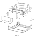
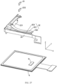
- FIG. 26 is a partial exploded diagram of the camera module 100 shown in FIG. 3 according to another embodiment.
- FIG. 27 is a partial exploded diagram of the motor 1 shown in FIG. 26 according to an embodiment.
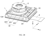
- FIG. 28 is a partial diagram of a structure of the camera module 100 shown in FIG. 3 according to another embodiment.
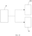
- the focus drive module 20 further includes a first flexible circuit board 24.
- the first flexible circuit board 24 is electrically connected between the focus circuit board 231 and the module circuit board 4.
- the plurality of ports of the focus drive chip 232 may be electrically connected to the module circuit board 4 through the focus circuit board 231 and the first flexible circuit board 24.
- the controller 8 controls the focus drive chip 232 to be in a working state, and simultaneously controls the drive chip 31 of the variable aperture 3 to be in a non-working state (for example, the drive chip 31 of the variable aperture 3 cannot form a current loop).
- an SDA signal may be transmitted to the SDA signal end of the focus drive chip 232 through the module circuit board 4, the first flexible circuit board 24, and the focus circuit board 231.
- an SCL signal may be transmitted to the SCL signal end of the focus drive chip 232 through the module circuit board 4, the first flexible circuit board 24, and the focus circuit board 231.
- an external power supply may supply power to the focus drive chip 232 through the module circuit board 4, the first flexible circuit board 24, and the focus circuit board 231.
- the first flexible circuit board 24 may alternatively be located in peripheral length space of the image stabilization carrier 12, so that the first flexible circuit board 24 has a relatively long cantilever, thereby implementing a relatively small motion reaction force. It may be understood that, when the image stabilization carrier 12 moves in the X-Y plane relative to the base 11, the first flexible circuit board 24 is bent or deformed, and generates an acting force in an opposite direction, that is, a motion reaction force. In this way, the motion reaction force of the first flexible circuit board 24 is reduced by increasing a length of the first flexible circuit board 24. If the motion reaction force of the first flexible circuit board 24 appears in the following, refer to an explanation of the motion reaction force of the first flexible circuit board 24. Details are not described again.
- the variable aperture 3 further includes a second flexible circuit board 32.
- One end of the second flexible circuit board 32 is electrically connected to the plurality of ports of the drive chip 31 of the variable aperture 3, and the other end thereof is electrically connected to the first flexible circuit board 24.
- the plurality of ports of the drive chip 31 of the variable aperture 3 may be electrically connected to the module circuit board 4 through the second flexible circuit board 32 and the first flexible circuit board 24.
- the second flexible circuit board 32 and the first flexible circuit board 24 may be of an integrally formed structure.
- the second flexible circuit board 32 and the first flexible circuit board 24 may be two independent circuit boards. Then, the two independent circuit boards are electrically connected through an electrical connector.
- the controller 8 controls the focus drive chip 232 to be in a non-working state (for example, the focus drive chip 232 cannot form a current loop), and simultaneously controls the drive chip 31 of the variable aperture 3 to be in a working state.
- an SDA signal may be transmitted to the SDA signal end of the drive chip 31 of the variable aperture 3 through the module circuit board 4, the first flexible circuit board 24, and the second flexible circuit board 32.
- an SCL signal may be transmitted to the SCL signal end of the drive chip 31 of the variable aperture 3 through the module circuit board 4, the first flexible circuit board 24, and the second flexible circuit board 32.
- an external power supply may supply power to the drive chip 31 of the variable aperture 3 through the module circuit board 4, the first flexible circuit board 24, and the second flexible circuit board 32.
- the second flexible circuit board 32 is in a top-down bent and folded state, so that when the distance between the focus carrier 21 and the image stabilization carrier 12 changes, bendable performance of the second flexible circuit board 32 is used to offset the distance change, to ensure that a circuit is not easily disconnected, that is, improve circuit stability.
- a very small motion reaction force of the second flexible circuit board 32 may also be implemented.
- the second flexible circuit board 32 is located on the top of the motor 1, and a projection of the second flexible circuit board 32 on the motor 1 is staggered with a focus magnet.
- the second flexible circuit board 32 uses magnetic-free space on the top of the motor 1, thereby reducing impact on the focus magnet of the motor 1.
- a position of the second flexible circuit board 32 is not specifically limited.
- circuit settings of the focus drive chip 232 and the drive chip 31 of the variable aperture 3 are not specifically limited.
Landscapes
- Physics & Mathematics (AREA)
- General Physics & Mathematics (AREA)
- Optics & Photonics (AREA)
- Engineering & Computer Science (AREA)
- Chemical & Material Sciences (AREA)
- Combustion & Propulsion (AREA)
- Electromagnetism (AREA)
- Power Engineering (AREA)
- Signal Processing (AREA)
- Lens Barrels (AREA)
- Adjustment Of Camera Lenses (AREA)
Applications Claiming Priority (2)
| Application Number | Priority Date | Filing Date | Title |
|---|---|---|---|
| CN202310152040.7A CN117590618B (zh) | 2023-02-15 | 2023-02-15 | 马达、摄像模组以及电子设备 |
| PCT/CN2024/075800 WO2024169692A1 (zh) | 2023-02-15 | 2024-02-04 | 马达、摄像模组以及电子设备 |
Publications (2)
| Publication Number | Publication Date |
|---|---|
| EP4579321A1 true EP4579321A1 (de) | 2025-07-02 |
| EP4579321A4 EP4579321A4 (de) | 2026-01-21 |
Family
ID=89910338
Family Applications (1)
| Application Number | Title | Priority Date | Filing Date |
|---|---|---|---|
| EP24756066.7A Pending EP4579321A4 (de) | 2023-02-15 | 2024-02-04 | Motor, kameramodul und elektronische vorrichtung |
Country Status (4)
| Country | Link |
|---|---|
| US (1) | US20250237883A1 (de) |
| EP (1) | EP4579321A4 (de) |
| CN (2) | CN117590618B (de) |
| WO (1) | WO2024169692A1 (de) |
Families Citing this family (7)
| Publication number | Priority date | Publication date | Assignee | Title |
|---|---|---|---|---|
| CN119449930B (zh) * | 2023-08-04 | 2025-11-11 | 华为技术有限公司 | 摄像模组以及电子设备 |
| CN222339499U (zh) * | 2023-12-29 | 2025-01-10 | 华为技术有限公司 | 镜头驱动装置、摄像头模组及电子设备 |
| CN120711285A (zh) * | 2024-04-02 | 2025-09-26 | 华为技术有限公司 | 一种对焦防抖马达、摄像模组及电子设备 |
| CN118433504B (zh) * | 2024-07-04 | 2024-09-27 | 宁波金芯旺光电科技有限公司 | 驱动组件和摄像装置 |
| CN119299815A (zh) * | 2024-09-13 | 2025-01-10 | 维沃移动通信有限公司 | 马达、摄像头模组电子设备 |
| CN119316712B (zh) * | 2024-09-24 | 2025-10-28 | 华为技术有限公司 | 马达、摄像头模组及电子设备 |
| CN120935442A (zh) * | 2025-06-16 | 2025-11-11 | 宁波舜宇光电信息有限公司 | 摄像模组及其马达 |
Family Cites Families (20)
| Publication number | Priority date | Publication date | Assignee | Title |
|---|---|---|---|---|
| US7881598B1 (en) * | 2009-12-03 | 2011-02-01 | Tdk Taiwan Corporation | Anti-shake auto-focus modular structure |
| US8861946B2 (en) * | 2013-03-07 | 2014-10-14 | Jahwa Electronics Co., Ltd. | Device for driving camera lens module in portable terminal |
| CN105190429B (zh) * | 2013-03-29 | 2018-09-14 | 磁化电子株式会社 | 照相机透镜模块 |
| US9372352B2 (en) * | 2013-08-23 | 2016-06-21 | Samsung Electro-Mechanics Co., Ltd. | Lens driving device and camera module including the same |
| CN203745709U (zh) * | 2014-01-10 | 2014-07-30 | 瑞声声学科技(常州)有限公司 | 镜头驱动装置 |
| KR101725442B1 (ko) * | 2014-03-07 | 2017-04-11 | 자화전자(주) | 카메라 렌즈 모듈 |
| KR101600574B1 (ko) * | 2015-02-17 | 2016-03-21 | (주) 엠디펄스 | 카메라 모듈 |
| KR102013190B1 (ko) * | 2015-09-25 | 2019-08-22 | 자화전자(주) | 카메라 렌즈 모듈 |
| CN105573014A (zh) * | 2016-01-22 | 2016-05-11 | 南昌欧菲光电技术有限公司 | 具有对焦及防抖功能的摄像头模组 |
| KR20170110298A (ko) * | 2016-03-23 | 2017-10-11 | 자화전자(주) | 렌즈구동장치 |
| CN108508678B (zh) * | 2017-02-27 | 2021-11-09 | 纳木加有限公司 | Ois摄像头模块及包括该ois摄像头模块的双摄像头系统 |
| KR102029532B1 (ko) * | 2017-06-12 | 2019-10-07 | 삼성전기주식회사 | 렌즈 구동 장치 및 이를 포함하는 카메라 모듈 |
| CN109709741B (zh) * | 2017-10-26 | 2024-06-14 | 华为技术有限公司 | 光学防抖装置 |
| CN109348102B (zh) * | 2018-10-25 | 2024-06-04 | 信利光电股份有限公司 | 单轴防抖的移轴防抖模块及潜望式防抖模组 |
| CN212115444U (zh) * | 2020-02-17 | 2020-12-08 | 华为技术有限公司 | 一种摄像模组及电子设备 |
| WO2021223223A1 (zh) * | 2020-05-08 | 2021-11-11 | 南昌欧菲光电技术有限公司 | 防抖组件、摄像模组及电子设备 |
| CN111650715A (zh) * | 2020-06-15 | 2020-09-11 | 瑞声通讯科技(常州)有限公司 | 镜头模组 |
| CN214586188U (zh) * | 2020-12-31 | 2021-11-02 | 高瞻创新科技有限公司 | 一种防抖对焦马达及其应用模组 |
| CN113109950B (zh) * | 2021-04-28 | 2023-12-01 | 新思考电机有限公司 | 光学防抖弹性支撑机构、防抖和透镜驱动装置及摄像装置、电子设备 |
| CN113489888B (zh) * | 2021-08-03 | 2023-05-19 | Oppo广东移动通信有限公司 | 摄像头模组及电子设备 |
-
2023
- 2023-02-15 CN CN202310152040.7A patent/CN117590618B/zh active Active
-
2024
- 2024-02-04 CN CN202480004214.8A patent/CN119998714A/zh active Pending
- 2024-02-04 EP EP24756066.7A patent/EP4579321A4/de active Pending
- 2024-02-04 WO PCT/CN2024/075800 patent/WO2024169692A1/zh not_active Ceased
-
2025
- 2025-04-11 US US19/176,858 patent/US20250237883A1/en active Pending
Also Published As
| Publication number | Publication date |
|---|---|
| CN119998714A (zh) | 2025-05-13 |
| EP4579321A4 (de) | 2026-01-21 |
| US20250237883A1 (en) | 2025-07-24 |
| CN117590618A (zh) | 2024-02-23 |
| CN117590618B (zh) | 2024-08-27 |
| WO2024169692A1 (zh) | 2024-08-22 |
Similar Documents
| Publication | Publication Date | Title |
|---|---|---|
| EP4579321A1 (de) | Motor, kameramodul und elektronische vorrichtung | |
| EP4579320A1 (de) | Motor, kameramodul und elektronische vorrichtung | |
| EP4465645A1 (de) | Verwackelungsschutzanordnung, kameramodul und elektronische vorrichtung | |
| CN117590669B (zh) | 可变光圈、摄像模组以及电子设备 | |
| US11119294B2 (en) | Optical system | |
| CN115550535B (zh) | 防抖组件、摄像模组及电子设备 | |
| EP4554244A1 (de) | Linsenmotor, kameramodul und elektronische vorrichtung | |
| EP4403981A1 (de) | Optische verwackelungsschutzeinheit, kameramodul und elektronische vorrichtung | |
| WO2025044365A1 (zh) | 感光组件、摄像头模组以及电子设备 | |
| CN215344794U (zh) | 拍摄装置以及电子设备 | |
| CN115499572B (zh) | 一种摄像头模组和电子设备 | |
| CN215344795U (zh) | 防抖机构、拍摄装置以及电子设备 | |
| CN218387701U (zh) | 防抖组件、摄像模组及电子设备 | |
| CN218162616U (zh) | 一种摄像头模组和电子设备 | |
| CN215344793U (zh) | 摄像模组及电子设备 | |
| CN115407475B (zh) | 光学镜头、摄像模组以及电子设备 | |
| CN115695971A (zh) | 电路板、摄像模组及电子设备 | |
| CN219802461U (zh) | 一种摄像头模组和电子设备 | |
| CN118540558B (zh) | 摄像头组件以及电子设备 | |
| CN115499571B (zh) | 一种摄像头模组、防抖组件和电子设备 | |
| CN219999459U (zh) | 一种摄像头模组和电子设备 | |
| CN218514442U (zh) | 摄像模组及电子设备 | |
| CN217283086U (zh) | 电路板、底座、摄像模组及电子设备 | |
| CN118573987A (zh) | 一种摄像头模组和电子设备 | |
| CN117979141A (zh) | 摄像组件、摄像模组及电子设备 |
Legal Events
| Date | Code | Title | Description |
|---|---|---|---|
| STAA | Information on the status of an ep patent application or granted ep patent |
Free format text: STATUS: THE INTERNATIONAL PUBLICATION HAS BEEN MADE |
|
| PUAI | Public reference made under article 153(3) epc to a published international application that has entered the european phase |
Free format text: ORIGINAL CODE: 0009012 |
|
| STAA | Information on the status of an ep patent application or granted ep patent |
Free format text: STATUS: REQUEST FOR EXAMINATION WAS MADE |
|
| 17P | Request for examination filed |
Effective date: 20250328 |
|
| AK | Designated contracting states |
Kind code of ref document: A1 Designated state(s): AL AT BE BG CH CY CZ DE DK EE ES FI FR GB GR HR HU IE IS IT LI LT LU LV MC ME MK MT NL NO PL PT RO RS SE SI SK SM TR |
|
| A4 | Supplementary search report drawn up and despatched |
Effective date: 20251222 |
|
| RIC1 | Information provided on ipc code assigned before grant |
Ipc: G02B 27/64 20060101AFI20251216BHEP Ipc: H04N 23/55 20230101ALI20251216BHEP Ipc: H04N 23/68 20230101ALI20251216BHEP Ipc: G02B 7/09 20210101ALI20251216BHEP Ipc: G03B 5/00 20210101ALI20251216BHEP Ipc: G03B 13/36 20210101ALI20251216BHEP |