EP4579252A1 - Circuit board test terminal - Google Patents
Circuit board test terminal Download PDFInfo
- Publication number
- EP4579252A1 EP4579252A1 EP23880065.0A EP23880065A EP4579252A1 EP 4579252 A1 EP4579252 A1 EP 4579252A1 EP 23880065 A EP23880065 A EP 23880065A EP 4579252 A1 EP4579252 A1 EP 4579252A1
- Authority
- EP
- European Patent Office
- Prior art keywords
- unit
- circuit board
- terminal
- test
- extension
- Prior art date
- Legal status (The legal status is an assumption and is not a legal conclusion. Google has not performed a legal analysis and makes no representation as to the accuracy of the status listed.)
- Pending
Links
Images




Classifications
-
- G—PHYSICS
- G01—MEASURING; TESTING
- G01R—MEASURING ELECTRIC VARIABLES; MEASURING MAGNETIC VARIABLES
- G01R1/00—Details of instruments or arrangements of the types included in groups G01R5/00 - G01R13/00 and G01R31/00
- G01R1/02—General constructional details
- G01R1/04—Housings; Supporting members; Arrangements of terminals
- G01R1/0408—Test fixtures or contact fields; Connectors or connecting adaptors; Test clips; Test sockets
-
- G—PHYSICS
- G01—MEASURING; TESTING
- G01R—MEASURING ELECTRIC VARIABLES; MEASURING MAGNETIC VARIABLES
- G01R1/00—Details of instruments or arrangements of the types included in groups G01R5/00 - G01R13/00 and G01R31/00
- G01R1/02—General constructional details
- G01R1/04—Housings; Supporting members; Arrangements of terminals
- G01R1/0408—Test fixtures or contact fields; Connectors or connecting adaptors; Test clips; Test sockets
- G01R1/0416—Connectors, terminals
-
- G—PHYSICS
- G01—MEASURING; TESTING
- G01R—MEASURING ELECTRIC VARIABLES; MEASURING MAGNETIC VARIABLES
- G01R31/00—Arrangements for testing electric properties; Arrangements for locating electric faults; Arrangements for electrical testing characterised by what is being tested not provided for elsewhere
- G01R31/28—Testing of electronic circuits, e.g. by signal tracer
- G01R31/2801—Testing of printed circuits, backplanes, motherboards, hybrid circuits or carriers for multichip packages [MCP]
- G01R31/2806—Apparatus therefor, e.g. test stations, drivers, analysers, conveyors
- G01R31/2808—Holding, conveying or contacting devices, e.g. test adapters, edge connectors, extender boards
-
- G—PHYSICS
- G01—MEASURING; TESTING
- G01R—MEASURING ELECTRIC VARIABLES; MEASURING MAGNETIC VARIABLES
- G01R31/00—Arrangements for testing electric properties; Arrangements for locating electric faults; Arrangements for electrical testing characterised by what is being tested not provided for elsewhere
- G01R31/28—Testing of electronic circuits, e.g. by signal tracer
- G01R31/2801—Testing of printed circuits, backplanes, motherboards, hybrid circuits or carriers for multichip packages [MCP]
- G01R31/281—Specific types of tests or tests for a specific type of fault, e.g. thermal mapping, shorts testing
- G01R31/2815—Functional tests, e.g. boundary scans, using the normal I/O contacts
-
- G—PHYSICS
- G01—MEASURING; TESTING
- G01R—MEASURING ELECTRIC VARIABLES; MEASURING MAGNETIC VARIABLES
- G01R31/00—Arrangements for testing electric properties; Arrangements for locating electric faults; Arrangements for electrical testing characterised by what is being tested not provided for elsewhere
- G01R31/50—Testing of electric apparatus, lines, cables or components for short-circuits, continuity, leakage current or incorrect line connections
- G01R31/66—Testing of connections, e.g. of plugs or non-disconnectable joints
- G01R31/70—Testing of connections between components and printed circuit boards
Definitions
- the present invention relates to a circuit board test terminal, and more particularly, to a terminal for testing an electronic component assembled with a circuit board.
- PCB Printed circuit bounds
- the PCBs each have a structure in which a conductor and an insulator are stacked in the form of a board, and a plurality of electric/electronic components such as semiconductors, capacitors, or resistors may be mounted thereon.
- the mounted electric/electronic components may be electrically connected to each other through an electric line circuit printed on the PCB.
- electric lines may be efficiently designed to reduce a size of an electronic equipment, and improve performance and productivity thereof.
- the plurality of electric/electronic components mounted on the PCB may transmit or receive electrical signals.
- an amount of electrical signals to be transmitted or received increases or high-speed processing of signals is required, a phenomenon in which a signal processing speed is decreased occurs, and this causes performance degradation of the PCB.
- methods such as a method of increasing the number of layers of the PCB to increase accommodating capacity for the components, are used.
- test device may be used to test whether the electronic components normally operate.
- the test device is one, a worker may make a test right away with two hands by gripping a test probe with one hand to bring the test probe into contact with a target point on a circuit board, and gripping a ground probe with the other hand to bring the ground probe into contact with a ground point on the circuit board.
- testing with the test devices one by one as above causes problems that it takes much time to perform the testing, and results output by the test devices cannot be visually seen at a glance.
- An object of the present invention for solving the above problems is to provide a circuit board test terminal capable of rapidly performing testing at once without an electrical short-circuit occurring between various types of test devices when an electronic component element, an electric circuit, or the like, which is mounted on a circuit board, is tested for whether to properly operate.
- the present invention provides a circuit board test terminal including a board part, and an extension part extending from the board part to be connected to a test point of a circuit board, wherein the board part includes: a plate unit that supports a lower portion; a partition unit disposed on the plate unit to divide the plate unit into a plurality of areas, and having a predetermined height; and a terminal unit disposed on each of the divided areas, wherein a test probe that tests the circuit board is in contact with the terminal unit.
- a holding groove having a predetermine depth may be defined in an upper end of the partition unit along an edge of the partition unit.
- An inclination guide groove may be defined in a top surface of the terminal unit, wherein the inclination guide groove is a groove having a predetermined inclination to be inclined toward the holding groove defined in the partition unit adjacent thereto.
- a vertical guide groove to which an end of the test probe is vertically inserted may be defined in the terminal unit.
- the vertical guide groove may be defined in a central portion of the terminal unit.
- the partition unit may include an electrical insulation material.
- the extension part may include an extension unit having one end that is connected to the terminal unit, and a coupling unit coupled to the other end of the extension unit and coupled to the test point.
- the coupling unit may be separated from and coupled to the extension unit.
- the coupling unit may have an end having a ring shape.
- the extension unit may be provided in plurality, and one end of each of a plurality of extension units may be connected to a different terminal unit.
- the coupling unit may be coupled to the other end of each of the extension units so as to be coupled to a plurality of test points.
- the circuit board test terminal may further include a connecting unit that electrically connects the terminal unit to the extension unit, wherein the connecting unit is coupled to one side of the terminal unit.
- the present invention may include a circuit board test terminal, and a test device including a test probe having an end, which is in contact with the circuit board test terminal, and a ground probe connected to a circuit board to be grounded, wherein the circuit board test terminal includes a board part, and an extension part extending from the board part to be connected to a test point of a circuit board, wherein the board part includes: a plate unit that supports a lower portion; a partition unit disposed on the plate unit to divide the plate unit into a plurality of areas, and having a predetermined height; and a terminal unit disposed on each of the divided areas, wherein a test probe that tests the circuit board is on contact with the terminal unit.
- the various types of test devices may be simply connected to perform the testing at once so that the testing is rapidly performed.
- the testing may be performed at once through the various types of test devices to easily compare the values measured by the test devices.
- the test devices necessary for performing the testing may be rapidly separated even after the testing is performed.
- the present invention relates to a circuit board test terminal 10 (hereinafter referred to as a "test terminal"), and the test terminal 10 may include a board part 100 and an extension part 150.
- the board part 100 is a component to which a test probe 210 is connected, and the board part 100 may include a plate unit 110, a partition unit 120, and a terminal unit 130.
- the planar shape of the plate unit 110 may be, for example, a rectangular shape, a circular shape, or the like, but is not limited thereto.
- the plate unit 110 may be disposed below the partition unit 120 and the terminal unit 130.
Landscapes
- Engineering & Computer Science (AREA)
- Physics & Mathematics (AREA)
- General Physics & Mathematics (AREA)
- Computer Hardware Design (AREA)
- Microelectronics & Electronic Packaging (AREA)
- General Engineering & Computer Science (AREA)
- Measuring Leads Or Probes (AREA)
- Testing Of Individual Semiconductor Devices (AREA)
- Tests Of Electronic Circuits (AREA)
Abstract
Description
- The present application claims the benefit of the priority of
Korean Patent Application No. 10-2022-0133602, filed on October 17, 2022 - The present invention relates to a circuit board test terminal, and more particularly, to a terminal for testing an electronic component assembled with a circuit board.
- Printed circuit bounds (PCB) are necessary parts used for almost every electronic equipment, and are printed circuit boards that are wired and provided on insulation plates so as to circuitally connect electric/electronic components. The PCBs each have a structure in which a conductor and an insulator are stacked in the form of a board, and a plurality of electric/electronic components such as semiconductors, capacitors, or resistors may be mounted thereon. The mounted electric/electronic components may be electrically connected to each other through an electric line circuit printed on the PCB. In the PCB, electric lines may be efficiently designed to reduce a size of an electronic equipment, and improve performance and productivity thereof.
- The plurality of electric/electronic components mounted on the PCB may transmit or receive electrical signals. However, when an amount of electrical signals to be transmitted or received increases or high-speed processing of signals is required, a phenomenon in which a signal processing speed is decreased occurs, and this causes performance degradation of the PCB. In order to resolve the decrease in signal processing speed, methods such as a method of increasing the number of layers of the PCB to increase accommodating capacity for the components, are used.
- Meanwhile, as it is difficult to check through the naked eyes whether the electronic components such as semiconductors, capacitors, or resistors, which are mounted on the PCB, are properly mounted on the PCB, a separate test device may be used to test whether the electronic components normally operate. When the test device is one, a worker may make a test right away with two hands by gripping a test probe with one hand to bring the test probe into contact with a target point on a circuit board, and gripping a ground probe with the other hand to bring the ground probe into contact with a ground point on the circuit board. However, if there are various types of test devices, testing with the test devices one by one as above causes problems that it takes much time to perform the testing, and results output by the test devices cannot be visually seen at a glance. In addition, when the testing is performed at once by connecting test probes to test points provided on the PCB, respectively, by using a method such as soldering so as to connect the various types of test devices to the target points on the circuit board at once, there are problems that the probes may be in contact with each other to cause an electrical short-circuit, and there is inconvenience to perform a separate process so as to remove the test probes having been connected through soldering or the like after the testing is performed.
- Accordingly, there is a need for technical development to solve the problems as above.
- An object of the present invention for solving the above problems is to provide a circuit board test terminal capable of rapidly performing testing at once without an electrical short-circuit occurring between various types of test devices when an electronic component element, an electric circuit, or the like, which is mounted on a circuit board, is tested for whether to properly operate.
- As one embodiment of the present invention, the present invention provides a circuit board test terminal including a board part, and an extension part extending from the board part to be connected to a test point of a circuit board, wherein the board part includes: a plate unit that supports a lower portion; a partition unit disposed on the plate unit to divide the plate unit into a plurality of areas, and having a predetermined height; and a terminal unit disposed on each of the divided areas, wherein a test probe that tests the circuit board is in contact with the terminal unit.
- A holding groove having a predetermine depth may be defined in an upper end of the partition unit along an edge of the partition unit.
- An inclination guide groove may be defined in a top surface of the terminal unit, wherein the inclination guide groove is a groove having a predetermined inclination to be inclined toward the holding groove defined in the partition unit adjacent thereto.
- A vertical guide groove to which an end of the test probe is vertically inserted may be defined in the terminal unit.
- The vertical guide groove may be defined in a central portion of the terminal unit.
- The partition unit may include an electrical insulation material.
- The extension part may include an extension unit having one end that is connected to the terminal unit, and a coupling unit coupled to the other end of the extension unit and coupled to the test point.
- The coupling unit may be separated from and coupled to the extension unit.
- The coupling unit may have an end having a ring shape.
- The extension unit may be provided in plurality, and one end of each of a plurality of extension units may be connected to a different terminal unit. The coupling unit may be coupled to the other end of each of the extension units so as to be coupled to a plurality of test points.
- The circuit board test terminal may further include a connecting unit that electrically connects the terminal unit to the extension unit, wherein the connecting unit is coupled to one side of the terminal unit.
- As another embodiment of the present invention, the present invention may include a circuit board test terminal, and a test device including a test probe having an end, which is in contact with the circuit board test terminal, and a ground probe connected to a circuit board to be grounded, wherein the circuit board test terminal includes a board part, and an extension part extending from the board part to be connected to a test point of a circuit board, wherein the board part includes: a plate unit that supports a lower portion; a partition unit disposed on the plate unit to divide the plate unit into a plurality of areas, and having a predetermined height; and a terminal unit disposed on each of the divided areas, wherein a test probe that tests the circuit board is on contact with the terminal unit.
- According to the present invention, when the electronic components mounted on the circuit board are tested for whether to normally operate, the various types of test devices may be simply connected to perform the testing at once so that the testing is rapidly performed. The testing may be performed at once through the various types of test devices to easily compare the values measured by the test devices. In addition, the test devices necessary for performing the testing may be rapidly separated even after the testing is performed.
-
-
FIG. 1 is a schematic plan view illustrating a board part according to the present invention. -
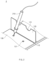
FIG. 2 is a perspective view illustrating a state in which a test probe is held in each of an inclination guide groove and a holding groove in a portion A inFIG. 1 . -
FIG. 3 illustrates (a) a schematic cross-sectional view taken along line BB' inFIG. 1 and (b) a schematic cross-sectional view taken along line CC' inFIG. 1 . -
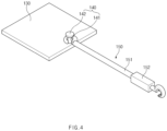
FIG. 4 is a schematic perspective view illustrating a state in which a terminal unit and an extension part are connected to each other through a connecting unit according to the present invention. - (a) to (d) of
FIG. 5 are schematic views illustrating a coupling unit according various embodiments of the present invention. -
FIG. 6 is a schematic perspective view illustrating a state in which an extension part is connected to an electronic component mounted on a circuit board according to the present invention. -
FIG. 7 is a schematic plan view illustrating a circuit board test assembly according to an embodiment of the present invention. - Hereinafter, preferred embodiments of the present invention will be described in detail with reference to the accompanying drawings to enable those skilled in the art to which the present invention pertains to easily carry out the present invention. The present invention may, however, be embodied in different forms and should not be construed as limited by the embodiments set forth herein.
- The parts unrelated to the description, or the detailed descriptions of related well-known art that may unnecessarily obscure subject matters of the present invention, will be ruled out in order to clearly describe the present invention. Like reference numerals refer to like elements throughout the whole specification.
- Moreover, terms or words used in this specification and claims should not be restrictively interpreted as ordinary meanings or dictionary-based meanings, but should be interpreted as meanings and concepts conforming to the scope of the present invention on the basis of the principle that an inventor can properly define the concept of a term to describe and explain his or her invention in the best ways.
- As one embodiment of the present invention, the present invention relates to a circuit board test terminal 10 (hereinafter referred to as a "test terminal"), and the
test terminal 10 may include aboard part 100 and anextension part 150. - The
board part 100 is a component to which atest probe 210 is connected, and theboard part 100 may include aplate unit 110, apartition unit 120, and aterminal unit 130. - The
plate unit 110 may have a flat shape having a predetermined area and thickness, and provide a bottom part of thetest terminal 10. - The planar shape of the
plate unit 110 may be, for example, a rectangular shape, a circular shape, or the like, but is not limited thereto. - The
plate unit 110 may be disposed below thepartition unit 120 and theterminal unit 130. - The
plate unit 110 may be made of an electrical insulation material to prevent current from flowing between a lower portion of theplate unit 110 and theterminal unit 130. Accordingly, even when theboard part 100 is moved to any position, theplate unit 110 may prevent electric noise from being introduced into theterminal unit 130 from a lower portion of theboard part 100. - The
partition unit 120 may be a wall having a small thickness, which is disposed on a top surface of theplate unit 110 and provided in a direction perpendicular to the top surface so as to divide theplate unit 110 into a plurality of areas. - The
partition unit 120 may be made of an electrical insulation material to shield a plurality ofterminal units 130 from each other so that a short-circuit is prevented from occurring. - As one embodiment, the
partition unit 120 may include ahorizontal part 120a and avertical part 120b. - The
horizontal part 120a may be disposed to be parallel to an edge of one surface of theplate unit 110 and the top surface of theplate unit 110, and divide the top surface of theplate unit 110 into a plurality of areas. - The
horizontal part 120a may be provided in one or plurality, and a plurality ofhorizontal parts 120a may be disposed on the top surface of theplate unit 110 according to a predetermined interval or arrangement. - The
vertical part 120b may be disposed in a direction perpendicular to thehorizontal part 120a, or disposed to cross thehorizontal part 120a at a predetermined angle. - A holding
groove 121 may be defined in an upper end of thepartition unit 120. - The holding
groove 121 may be a groove having a predetermined depth, which is disposed along an edge of the upper end of thepartition unit 120 in at least a partial region of the edge. - The shape of the holding
groove 121 may be, for example, a faceted shape, a curved surface shape, or the like, but is not limited thereto. - The
test probe 210 may be held in the holdinggroove 121. As an end of thetest probe 210 is in contact with theterminal unit 130, and also a side surface part of thetest probe 210 is in contact with the holdinggroove 121, thetest probe 210 may be held in the holdinggroove 121 while forming a predetermined angle. A circuit board may be tested through thetest probe 210 held in the holdinggroove 121, and while thetest probe 210 is held in the holdinggroove 121, a worker may perform another work so that work efficiency is improved. - The
terminal unit 130 may be disposed in each of the areas divided by thepartition unit 120 on theplate unit 130. - The
terminal unit 130 may include an electrically conductive metal material so as to be in contact with and electrically connected to thetest probe 210. For example, the electrically conductive metal material may be copper, aluminum, gold, silver, or the like. - The
terminal unit 130 may have an area and a shape corresponding to the shape of the area divided by thepartition unit 120. - The
terminal unit 130 may be provided in the form of a plate having a predetermined thickness and width in order to resolve inconvenience caused by testing in which thetest probe 210 is in direct contact with a pin or the like of a very smallelectronic component 320 mounted on acircuit board 300 according to the related art. Thus, the worker may solely bring thetest probe 210 into contact with theterminal unit 130 to obtain effects the same as those when thetest probe 210 is in direct contact with the pin, a printed electric circuit, or the like of the very smallelectronic component 320, which is connected to theterminal unit 130 through and theextension part 140. In addition, the testing may be simply performed to remarkably improve the work efficiency. - An
inclination guide groove 131 and avertical guide groove 132 may be defined in theterminal unit 130. - Referring to (b) of
FIG. 2 andFIG. 3 , the end of thetest probe 210 may be inserted into theinclination guide groove 131 to increase a contact area between thetest probe 210 and theterminal unit 130, and to provide an inclination in a direction, in which thetest probe 210 is disposed, so that thetest probe 210 is heled in the holdinggroove 121. - The
inclination guide groove 131 may be defined to be spaced a predetermined distance from thepartition unit 120 on a top surface of theterminal unit 130, and may be disposed to be more adjacent to an edge of theterminal unit 130 than thevertical guide groove 132. - Referring to
FIG. 2 andFIG. 3(b) , theinclination guide groove 131 may have a predetermined inclination inclined so that a virtual central line connecting a center of an opened top surface of theinclination guide groove 131 to a vertex of a lower end thereof faces the holdinggroove 121. Accordingly, as the end of thetest probe 210 is inserted into theinclination guide groove 131, and the side surface part thereof is held in the holdinggroove 121, thetest probe 210 may stand to be inclined at the predetermined angle. That is, theinclination guide groove 131 and the holdinggroove 210 corresponding to theinclination guide groove 131 may be disposed to be adjacent at a distance close to each other so that easy holding of thetest probe 210 is achieved. - The
inclination guide groove 131 may be provided in plurality to be disposed along the edge of theterminal unit 130. As a plurality ofinclination guide groove 131 are disposed, a plurality of types oftest probes 210 that measure different values from each other may be inserted at once into differentinclination guide grooves 131, respectively, in oneterminal unit 130, and the plurality of types oftest probes 210 may measure at once values of the sameelectronic component 320 electrically connected to theterminal unit 130. - As the end of the
test probe 210 is inserted and fixed to theinclination guide groove 131, a position of thetest probe 210 held in the holdinggroove 121 may also be stably fixed. - Referring to (a) of
FIG. 3 , thevertical guide groove 132 may be defined in a central portion of the top surface of theterminal unit 130. Thevertical guide groove 132 may be disposed so that a virtual central line connecting a center of an opened top surface of thevertical guide groove 132 to a vertex of a lower end thereof faces the center of the opened top surface. - Compared to the
inclination guide groove 131, thevertical guide groove 132 may have a deeper depth, and the opened top surface thereof may have a smaller area so that when the end of thetest probe 210 is inserted into thevertical guide groove 132, thetest probe 210 stands in a direction perpendicular to the top surface of theterminal unit 130 even without being held in the holdinggroove 121. - As the
vertical guide groove 132 and theinclination guide groove 131 are defined in oneterminal unit 130, a plurality of types oftest probes 210 that measure different values from each other may be inserted at once intoinclination guide grooves 131 andvertical guide groove 132, respectively, and the plurality of types oftest probes 210 may measure at once values of the sameelectronic component 320 electrically connected to theterminal unit 130. - The
vertical guide groove 132 and theinclination guide groove 131 may be spaced a predetermined distance from each other so that the test probes 210 inserted into thevertical guide groove 132 and theinclination guide groove 131, respectively, are not in contact with each other. When contact between the test probes 210 occurs, current may flow even between the test probes 210 to cause an electrical short-circuit problem. As thevertical guide groove 132 and theinclination guide groove 131 are spaced a predetermined distance from each other to space the test probes 210, the problem as above may be prevented. - As the end of the
test probe 210 is inserted into thevertical guide groove 132 and a position thereof is fixed, a position of thetest probe 210 may also be stably fixed. - A connecting
unit 140 may be disposed on one side of theterminal unit 130. and connect theterminal unit 130 to theextension part 150. - The connecting
unit 140 may be coupled to the one side of theterminal unit 130. The coupling method may be, for example, a method of welding a lower end of the connectingunit 140 to one side of the top surface of theterminal unit 130, a method of screw-coupling the connectingunit 140 to one side of theterminal unit 130 through a spiral thread provided on a body of the connectingunit 140, or the like. However, the coupling method is not limited thereto. - The connecting
unit 140 may electrically connect theterminal unit 130 to theextension part 150. The connectingunit 140 may include an electrically conductive metal material so as to electrically connect theterminal unit 130 to theextension part 150. For example, the connectingunit 140 may include a material such as copper, aluminum, silver, gold, or tungsten, but is not limited thereto. - Referring to
FIG. 4 , the connectingunit 140 may include abody part 141, which is disposed in the direction perpendicular to the top surface of theterminal unit 130, and ahead part 142 provided on an upper end of thebody part 141. Thebody part 141 may have a shape such as a cylinder, a rectangular cylinder, or a faceted cylinder, and be coupled to anextension unit 151 of theextension part 150 so that theterminal unit 130 is coupled to theextension part 150. - The
extension part 150 may include theextension unit 151 and acoupling unit 152. - The
extension part 150 may freely space theboard part 100 from thecircuit board 300 so that theelectronic component 320 or the like mounted on thecircuit board 300 is tested using atest device 200 regardless of a position. - The
extension unit 151 may have one end connected to theterminal unit 130, and the other end connected to thecoupling unit 152. Specifically, the one end of theextension unit 151 may be connected to the body part of the connectingunit 140 coupled to theterminal unit 130. - Referring to
FIG. 4 , an annular structure made of an electrically conductive metal material may be provided on one end of theextension unit 151. The annular structure may be hooked with thebody part 141 of the connectingunit 140 to rapidly connect theextension unit 151 to the connectingunit 140. - The
extension unit 151 may include an extension line elongated in a direction from the annular structure provided on the one end to the other end. The extension line may include a metal layer (not shown) made of an electrically conductive material, which is connected to the annular structure provided on the one end of theextension unit 151, and an electrical insulation layer (not shown) which coats an outer surface of the metal layer with an electrical insulation material in a longitudinal direction thereof. A material of each of the metal layer and the electrical insulation layer of the extension line may be a plastically deformable material that is easily bent or has a curved surface provided thereon when force is applied thereto. For examples, the material of the metal layer may be copper, aluminum, or the like, and the material of the electrical insulation layer may be a natural rubber, a synthetic rubber, a synthetic resin, or the like. - The
coupling unit 152 may be coupled to the other end of theextension unit 151. - The
coupling unit 152 may be coupled to theextension unit 151 through a separable and couplable structure. - The
coupling unit 152 may include acoupling part 153, asupport 154, and each ofring parts - The
coupling part 153 capable of coupled to the other end of theextension unit 151 may be provided on one end of thecoupling unit 152. Thecoupling part 153 may be, for example, a bolt or the like, and thecoupling part 153 may be coupled to the other end of theextension unit 151 through separable and couplable bolt coupling. - The
support 154 may have one end provided with thecoupling part 153, and the other end provided with each of thering parts - The
support 154 may be provided in the form of a faceted cylinder, for example, a rectangular cylinder, a pentagonal cylinder, or the like. As thesupport 154 has a shape of a faceted cylinder, thesupport 154 may be stably positioned without rolling on thecircuit board 300. Thus, a position, at which each of thering parts electronic components 320 on thecircuit board 300, and a position adjacent thereto may be stably supported. - As the
support 154 includes an electrical insulation material, current may not be allowed to flow to thecoupling unit 152 through thesupport 154 even when thesupport 154 is in contact with other printed electric circuit or the like on thecircuit board 300. - Hereinafter, the
ring parts FIG. 5 . - Referring to (a) of
FIG. 5 andFIG. 6 , as one embodiment of the present invention, afirst ring part 152a may be provided on the other end of thecoupling unit 152. Thefirst ring part 152a may have a shape having a circumference that is at most half of a circumference of a circular ring. However, thefirst ring part 152a is not limited to the circular ring, and may have a shape of an oval ring or other closed curve ring. Thefirst ring part 152a may have a structure capable of being easily hooked with a pin or the like of theelectronic component 320 of thecircuit board 300 so that thefirst ring part 152a is rapidly coupled. Thefirst ring part 152a may be made of an electrically conductive metal material, and an outer surface thereof except an inner surface of the ring, which is in contact with the pin, may be coated with an electrical insulation material so as to prevent a short-circuit caused by contact with another pin adjacent to the pin. - Referring to (b) of
FIG. 5 , as another embodiment of the present invention, asecond ring part 152b may be provided on the other end of thecoupling unit 152. Thesecond ring part 152b may have a shape of a circular ring. Thesecond ring part 152b may be made of an electrically conductive metal material, and an outer surface thereof except an inner surface of the circular ring, which is in contact with a pin of theelectronic component 320, may be coated with an electrical insulation material so as to prevent a short-circuit caused by contact with another pin adjacent to the pin. - Referring to (c) of
FIG. 5 , as still another embodiment of the present invention, athird ring part 152c may be provided on the other end of thecoupling unit 152. Thethird ring part 152c may have a shape of a "V"- or "Y"- shaped ring. Thethird ring part 152c may be made of an electrically conductive metal material, and an outer surface thereof except an inner surface of the "V"- or "Y"- shaped ring, which is in contact with a pin of theelectronic component 320, may be coated with an electrical insulation material so as to prevent a short-circuit caused by contact with another pin adjacent to the pin. - Referring to (d) of
FIG. 5 , as still another embodiment of the present invention, afourth ring part 152d may be provided on the other end of thecoupling unit 152. Thefourth ring part 152d may have a shape having a circumference that is greater than half of a circumference of a circular ring. However, thefourth ring part 152d is not limited to the circular ring, and may have a shape of an oval ring or other closed curve ring. Thefourth ring part 152d may be made of an electrically conductive metal material, and an outer surface thereof except an inner surface of the ring, which is in contact with a pin of theelectronic component 320, may be coated with an electrical insulation material so as to prevent a short-circuit caused by contact with another pin adjacent to the pin. - Referring to
FIG. 7 , a circuitboard test assembly 20 may include a circuitboard test terminal 10 and atest device 200. Thetest device 200 may include atest probe 210 having one end, which is in contact with aterminal unit 130 of the circuitboard test terminal 10, and aground probe 220 having one end which is connected to aground point 310 of acircuit board 300 so as to be grounded. - As the
ground probe 220 is grounded, thetest device 200 may set a reference value for values measured by thetest probe 210, and reduce noise from being introducing into thetest probe 210. Accordingly, reliability of the values measured by thetest probe 210 may be improved. - The
test probe 210 may be in contact with aterminal unit 130 to test whether anelectronic component 320, a printed electric circuit, or the like, which is electrically connected to the circuitboard test terminal 10, operates normally on thecircuit board 300. - The
circuit board 300 may include various types of circuit boards, for example, a printed circuit board (PCB), a flexible printed circuit board (FPCB), a rigid-flexible printed circuit board (RF-PCB), and a high density interconnection (HDI), and preferably, thecircuit board 100 may be a PCB circuit board. However, thecircuit board 100 is not limited thereto. - Each of the
electronic components 320 in which an electric circuit is printed through printed electronics may be mounted at a predetermined position on thecircuit board 300. - The specific description of the circuit
board test terminal 10 may be replaced with the content described above. - Although the present invention has been described with reference to the limited embodiments and drawings, the present invention is not limited thereto and may be variously implemented by those of ordinary skill in the art to which the present invention pertains, within the technical idea of the present invention and an equivalent of the appended claims.
-
- 10:
- Circuit board test terminal
- 20:
- Circuit board test assembly
- 100:
- Board part
- 110:
- Plate unit
- 120:
- Partition unit
- 120:
- Horizontal part
- 120:
- Vertical part
- 121:
- Holding groove
- 130:
- Terminal unit
- 131:
- Inclination guide groove
- 132:
- Vertical guide groove
- 140:
- Connecting unit
- 150:
- Extension part
- 151:
- Extension unit
- 152:
- Coupling unit
- 200:
- Test device
- 210:
- Test probe
- 300:
- Circuit board
- 310:
- Ground point
- 320:
- Electronic component
Claims (12)
- A circuit board test terminal comprising:a board part; andan extension part extending from the board part to be connected to a test point of a circuit board,wherein the board part comprises:a plate unit configured to support a lower portion;a partition unit disposed on the plate unit to divide the plate unit into a plurality of areas, and having a predetermined height; anda terminal unit disposed on each of the divided areas,wherein a test probe configured to test the circuit board is in contact with the terminal unit.
- The circuit board test terminal of claim 1, wherein a holding groove having a predetermine depth is defined in an upper end of the partition unit along an edge of the partition unit.
- The circuit board test terminal of claim 2, wherein an inclination guide groove is defined in a top surface of the terminal unit, wherein the inclination guide groove is a groove having a predetermined inclination to be inclined toward the holding groove defined in the partition unit adjacent thereto.
- The circuit board test terminal of claim 1, wherein a vertical guide groove to which an end of the test probe is vertically inserted is defined in the terminal unit.
- The circuit board test terminal of claim 4, wherein the vertical guide groove is defined in a central portion of the terminal unit.
- The circuit board test terminal of claim 1, wherein the partition unit comprises an electrical insulation material.
- The circuit board test terminal of claim 1, wherein the extension part comprises:an extension unit having one end that is connected to the terminal unit; anda coupling unit coupled to the other end of the extension unit and coupled to the test point.
- The circuit board test terminal of claim 7, wherein the coupling unit is separated from and coupled to the extension unit.
- The circuit board test terminal of claim 7, wherein the coupling unit has an end having a ring shape.
- The circuit board test terminal of claim 7, wherein the extension unit is provided in plurality, and one end of each of a plurality of extension units is connected to a different terminal unit, and
the coupling unit is coupled to the other end of each of the extension units so as to be coupled to a plurality of test points. - The circuit board test terminal of claim 7, further comprising a connecting unit configured to electrically connect the terminal unit to the extension unit,
wherein the connecting unit is coupled to one side of the terminal unit. - A circuit board test assembly comprising:a circuit board test terminal; anda test device comprising a test probe having an end, which is in contact with the circuit board test terminal, and a ground probe connected to a circuit board to be grounded,wherein the circuit board test terminal comprises:a board part; andan extension part extending from the board part to be connected to a test point of a circuit board,wherein the board part comprises:a plate unit configured to support a lower portion;a partition unit disposed on the plate unit to divide the plate unit into a plurality of areas, and having a predetermined height; anda terminal unit disposed on each of the divided areas,wherein a test probe configured to test the circuit board is in contact with the terminal unit.
Applications Claiming Priority (2)
| Application Number | Priority Date | Filing Date | Title |
|---|---|---|---|
| KR1020220133602A KR102858854B1 (en) | 2022-10-17 | 2022-10-17 | Circuit board test terminal |
| PCT/KR2023/014566 WO2024085486A1 (en) | 2022-10-17 | 2023-09-22 | Circuit board test terminal |
Publications (2)
| Publication Number | Publication Date |
|---|---|
| EP4579252A1 true EP4579252A1 (en) | 2025-07-02 |
| EP4579252A4 EP4579252A4 (en) | 2025-11-26 |
Family
ID=90737905
Family Applications (1)
| Application Number | Title | Priority Date | Filing Date |
|---|---|---|---|
| EP23880065.0A Pending EP4579252A4 (en) | 2022-10-17 | 2023-09-22 | TEST TERMINAL FOR CIRCUIT BOARD |
Country Status (5)
| Country | Link |
|---|---|
| EP (1) | EP4579252A4 (en) |
| JP (1) | JP2025533667A (en) |
| KR (1) | KR102858854B1 (en) |
| CN (1) | CN119968571A (en) |
| WO (1) | WO2024085486A1 (en) |
Family Cites Families (16)
| Publication number | Priority date | Publication date | Assignee | Title |
|---|---|---|---|---|
| KR970054912A (en) * | 1995-12-27 | 1997-07-31 | 한승준 | Coupling structure of battery terminal |
| KR200253806Y1 (en) * | 2001-08-14 | 2001-11-22 | 동양기전 주식회사 | The terminal fusing assembly of motor |
| KR20060133242A (en) * | 2005-06-20 | 2006-12-26 | 삼성전자주식회사 | Liquid crystal display device and test device thereof and test method thereof |
| KR100730801B1 (en) * | 2005-12-28 | 2007-06-21 | 엠알 보드 인크 | Educational digital magnetic breadboard and electronic parts |
| KR100790988B1 (en) * | 2006-04-11 | 2008-01-03 | 삼성전자주식회사 | Handler for semiconductor device inspection to maintain stable temperature in test environment |
| KR20080092522A (en) * | 2007-04-12 | 2008-10-16 | 마이크로 인스펙션 주식회사 | Circuit board inspection device |
| JP2009121992A (en) * | 2007-11-15 | 2009-06-04 | Sharp Corp | Electronic circuit board and test equipment |
| KR100991367B1 (en) * | 2010-03-15 | 2010-11-02 | (주)아테코 | Module for testing display device |
| KR20130128258A (en) * | 2012-05-16 | 2013-11-26 | 정병직 | Tray for thin film battery test with excellent reliability |
| KR20170011553A (en) * | 2015-07-23 | 2017-02-02 | 삼성전자주식회사 | Test interface board and test system including the same |
| KR101885462B1 (en) * | 2017-02-17 | 2018-08-03 | 한국기술교육대학교 산학협력단 | Electronic kit for testing electronic circuit |
| KR102141368B1 (en) * | 2019-01-23 | 2020-08-05 | 박상량 | Socket for semiconductor device |
| KR102169588B1 (en) * | 2019-02-25 | 2020-10-23 | 이승용 | Test socket comprising pogo pin and interface, and test apparatus comprising the test socket |
| KR102249306B1 (en) * | 2019-07-09 | 2021-05-07 | 주식회사 아테코 | A test board for dyes obtained from wafer singulation, a test apparatus and a test method |
| KR102260861B1 (en) * | 2019-10-25 | 2021-06-07 | 마이크로 인스펙션 주식회사 | Inspection apparatus of printed circuit board and control method thereof |
| KR102712864B1 (en) * | 2020-08-12 | 2024-10-07 | 한국전력공사 | Cable connection device |
-
2022
- 2022-10-17 KR KR1020220133602A patent/KR102858854B1/en active Active
-
2023
- 2023-09-22 EP EP23880065.0A patent/EP4579252A4/en active Pending
- 2023-09-22 WO PCT/KR2023/014566 patent/WO2024085486A1/en not_active Ceased
- 2023-09-22 JP JP2025520029A patent/JP2025533667A/en active Pending
- 2023-09-22 CN CN202380072059.9A patent/CN119968571A/en active Pending
Also Published As
| Publication number | Publication date |
|---|---|
| KR102858854B1 (en) | 2025-09-11 |
| KR20240053464A (en) | 2024-04-24 |
| CN119968571A (en) | 2025-05-09 |
| WO2024085486A1 (en) | 2024-04-25 |
| EP4579252A4 (en) | 2025-11-26 |
| JP2025533667A (en) | 2025-10-07 |
Similar Documents
| Publication | Publication Date | Title |
|---|---|---|
| EP1607749B1 (en) | Test probe assembly for IC chips | |
| US4574235A (en) | Transmission line connector and contact set assembly for test site | |
| EP3842811B1 (en) | Inspection socket | |
| JP4450844B2 (en) | Measuring board for electronic component testing equipment | |
| CA1130876A (en) | High-frequency etched circuit board connection method | |
| EP3669196B1 (en) | Test device | |
| US20120119779A1 (en) | Signal sensing device and circuit boards | |
| EP1672742B1 (en) | Pin Connector | |
| CN210142148U (en) | Test fixture for observing current through a set of resistors | |
| KR101149748B1 (en) | Electric connection structure, terminal device, socket, device for testing electronic component, and method of manufacturing socket | |
| US6916990B2 (en) | High power interface | |
| US20030193323A1 (en) | Systems and methods for wideband single-end probing of variably spaced probe points | |
| US4825155A (en) | X-band logic test jig | |
| US7786741B2 (en) | Measuring tip for high-frequency measurement | |
| CN110213881A (en) | A kind of printed circuit board and test fixture | |
| TWI572868B (en) | Detection device and its probe module | |
| KR102858854B1 (en) | Circuit board test terminal | |
| US6498299B2 (en) | Connection structure of coaxial cable to electric circuit substrate | |
| JP6046200B2 (en) | Transmission line and inspection jig | |
| US6894516B1 (en) | Method and apparatus for implementing very high density probing (VHDP) of printed circuit board signals | |
| US7091732B2 (en) | Systems and methods for probing processor signals | |
| KR100313772B1 (en) | Test fixture for PCB | |
| US6293817B1 (en) | Extended length, high frequency contactor block | |
| CN108872651A (en) | Probe card | |
| JPH0750322A (en) | Terminal processing method for probe card and coaxial probe needle |
Legal Events
| Date | Code | Title | Description |
|---|---|---|---|
| STAA | Information on the status of an ep patent application or granted ep patent |
Free format text: STATUS: THE INTERNATIONAL PUBLICATION HAS BEEN MADE |
|
| PUAI | Public reference made under article 153(3) epc to a published international application that has entered the european phase |
Free format text: ORIGINAL CODE: 0009012 |
|
| STAA | Information on the status of an ep patent application or granted ep patent |
Free format text: STATUS: REQUEST FOR EXAMINATION WAS MADE |
|
| 17P | Request for examination filed |
Effective date: 20250328 |
|
| AK | Designated contracting states |
Kind code of ref document: A1 Designated state(s): AL AT BE BG CH CY CZ DE DK EE ES FI FR GB GR HR HU IE IS IT LI LT LU LV MC ME MK MT NL NO PL PT RO RS SE SI SK SM TR |
|
| A4 | Supplementary search report drawn up and despatched |
Effective date: 20251029 |
|
| RIC1 | Information provided on ipc code assigned before grant |
Ipc: G01R 31/28 20060101AFI20251023BHEP Ipc: G01R 1/04 20060101ALI20251023BHEP |
|
| DAV | Request for validation of the european patent (deleted) | ||
| DAX | Request for extension of the european patent (deleted) |