EP4579162A1 - Kühlvorrichtung und wasserreiniger damit - Google Patents
Kühlvorrichtung und wasserreiniger damit Download PDFInfo
- Publication number
- EP4579162A1 EP4579162A1 EP23885985.4A EP23885985A EP4579162A1 EP 4579162 A1 EP4579162 A1 EP 4579162A1 EP 23885985 A EP23885985 A EP 23885985A EP 4579162 A1 EP4579162 A1 EP 4579162A1
- Authority
- EP
- European Patent Office
- Prior art keywords
- cooling
- flow path
- frame
- fluid
- fluidly connected
- Prior art date
- Legal status (The legal status is an assumption and is not a legal conclusion. Google has not performed a legal analysis and makes no representation as to the accuracy of the status listed.)
- Pending
Links
Images


Classifications
-
- F—MECHANICAL ENGINEERING; LIGHTING; HEATING; WEAPONS; BLASTING
- F25—REFRIGERATION OR COOLING; COMBINED HEATING AND REFRIGERATION SYSTEMS; HEAT PUMP SYSTEMS; MANUFACTURE OR STORAGE OF ICE; LIQUEFACTION SOLIDIFICATION OF GASES
- F25D—REFRIGERATORS; COLD ROOMS; ICE-BOXES; COOLING OR FREEZING APPARATUS NOT OTHERWISE PROVIDED FOR
- F25D31/00—Other cooling or freezing apparatus
- F25D31/002—Liquid coolers, e.g. beverage cooler
-
- B—PERFORMING OPERATIONS; TRANSPORTING
- B67—OPENING, CLOSING OR CLEANING BOTTLES, JARS OR SIMILAR CONTAINERS; LIQUID HANDLING
- B67D—DISPENSING, DELIVERING OR TRANSFERRING LIQUIDS, NOT OTHERWISE PROVIDED FOR
- B67D1/00—Apparatus or devices for dispensing beverages on draught
- B67D1/08—Details
- B67D1/0857—Cooling arrangements
- B67D1/0869—Cooling arrangements using solid state elements, e.g. Peltier cells
-
- F—MECHANICAL ENGINEERING; LIGHTING; HEATING; WEAPONS; BLASTING
- F25—REFRIGERATION OR COOLING; COMBINED HEATING AND REFRIGERATION SYSTEMS; HEAT PUMP SYSTEMS; MANUFACTURE OR STORAGE OF ICE; LIQUEFACTION SOLIDIFICATION OF GASES
- F25B—REFRIGERATION MACHINES, PLANTS OR SYSTEMS; COMBINED HEATING AND REFRIGERATION SYSTEMS; HEAT PUMP SYSTEMS
- F25B21/00—Machines, plants or systems, using electric or magnetic effects
- F25B21/02—Machines, plants or systems, using electric or magnetic effects using Peltier effect; using Nernst-Ettinghausen effect
-
- F—MECHANICAL ENGINEERING; LIGHTING; HEATING; WEAPONS; BLASTING
- F25—REFRIGERATION OR COOLING; COMBINED HEATING AND REFRIGERATION SYSTEMS; HEAT PUMP SYSTEMS; MANUFACTURE OR STORAGE OF ICE; LIQUEFACTION SOLIDIFICATION OF GASES
- F25D—REFRIGERATORS; COLD ROOMS; ICE-BOXES; COOLING OR FREEZING APPARATUS NOT OTHERWISE PROVIDED FOR
- F25D23/00—General constructional features
- F25D23/006—General constructional features for mounting refrigerating machinery components
-
- F—MECHANICAL ENGINEERING; LIGHTING; HEATING; WEAPONS; BLASTING
- F28—HEAT EXCHANGE IN GENERAL
- F28D—HEAT-EXCHANGE APPARATUS, NOT PROVIDED FOR IN ANOTHER SUBCLASS, IN WHICH THE HEAT-EXCHANGE MEDIA DO NOT COME INTO DIRECT CONTACT
- F28D1/00—Heat-exchange apparatus having stationary conduit assemblies for one heat-exchange medium only, the media being in contact with different sides of the conduit wall, in which the other heat-exchange medium is a large body of fluid, e.g. domestic or motor car radiators
- F28D1/02—Heat-exchange apparatus having stationary conduit assemblies for one heat-exchange medium only, the media being in contact with different sides of the conduit wall, in which the other heat-exchange medium is a large body of fluid, e.g. domestic or motor car radiators with heat-exchange conduits immersed in the body of fluid
- F28D1/04—Heat-exchange apparatus having stationary conduit assemblies for one heat-exchange medium only, the media being in contact with different sides of the conduit wall, in which the other heat-exchange medium is a large body of fluid, e.g. domestic or motor car radiators with heat-exchange conduits immersed in the body of fluid with tubular conduits
- F28D1/047—Heat-exchange apparatus having stationary conduit assemblies for one heat-exchange medium only, the media being in contact with different sides of the conduit wall, in which the other heat-exchange medium is a large body of fluid, e.g. domestic or motor car radiators with heat-exchange conduits immersed in the body of fluid with tubular conduits the conduits being bent, e.g. in a serpentine or zig-zag
- F28D1/0472—Heat-exchange apparatus having stationary conduit assemblies for one heat-exchange medium only, the media being in contact with different sides of the conduit wall, in which the other heat-exchange medium is a large body of fluid, e.g. domestic or motor car radiators with heat-exchange conduits immersed in the body of fluid with tubular conduits the conduits being bent, e.g. in a serpentine or zig-zag the conduits being helically or spirally coiled
-
- B—PERFORMING OPERATIONS; TRANSPORTING
- B67—OPENING, CLOSING OR CLEANING BOTTLES, JARS OR SIMILAR CONTAINERS; LIQUID HANDLING
- B67D—DISPENSING, DELIVERING OR TRANSFERRING LIQUIDS, NOT OTHERWISE PROVIDED FOR
- B67D1/00—Apparatus or devices for dispensing beverages on draught
- B67D1/08—Details
- B67D1/0857—Cooling arrangements
-
- B—PERFORMING OPERATIONS; TRANSPORTING
- B67—OPENING, CLOSING OR CLEANING BOTTLES, JARS OR SIMILAR CONTAINERS; LIQUID HANDLING
- B67D—DISPENSING, DELIVERING OR TRANSFERRING LIQUIDS, NOT OTHERWISE PROVIDED FOR
- B67D2210/00—Indexing scheme relating to aspects and details of apparatus or devices for dispensing beverages on draught or for controlling flow of liquids under gravity from storage containers for dispensing purposes
- B67D2210/00002—Purifying means
- B67D2210/00005—Filters
- B67D2210/0001—Filters for liquid
-
- B—PERFORMING OPERATIONS; TRANSPORTING
- B67—OPENING, CLOSING OR CLEANING BOTTLES, JARS OR SIMILAR CONTAINERS; LIQUID HANDLING
- B67D—DISPENSING, DELIVERING OR TRANSFERRING LIQUIDS, NOT OTHERWISE PROVIDED FOR
- B67D2210/00—Indexing scheme relating to aspects and details of apparatus or devices for dispensing beverages on draught or for controlling flow of liquids under gravity from storage containers for dispensing purposes
- B67D2210/00028—Constructional details
- B67D2210/00047—Piping
- B67D2210/00062—Pipe joints
-
- B—PERFORMING OPERATIONS; TRANSPORTING
- B67—OPENING, CLOSING OR CLEANING BOTTLES, JARS OR SIMILAR CONTAINERS; LIQUID HANDLING
- B67D—DISPENSING, DELIVERING OR TRANSFERRING LIQUIDS, NOT OTHERWISE PROVIDED FOR
- B67D2210/00—Indexing scheme relating to aspects and details of apparatus or devices for dispensing beverages on draught or for controlling flow of liquids under gravity from storage containers for dispensing purposes
- B67D2210/00028—Constructional details
- B67D2210/00099—Temperature control
- B67D2210/00104—Cooling only
Definitions
- the present disclosure relates to a cooling device and a water purifier including the same, and more particularly, to a cooling device having a structure capable of improving heat-exchange efficiency and cooling efficiency while miniaturizing and reducing the weight of the product, and a water purifier including the same.
- a water purifier is a generic term of any device that can receive raw water, process it in a desired state, and then provide it to a user.
- the water purifier can filter the raw water using various types of filters and provide it to the user.
- the water purifier can filter the raw water so that it is suitable for drinking and provide it to the user.
- the water purifier that can perform additional functions in addition to simply filtering the raw water and providing it to the user is popular.
- the water purifier that can provide hot water, cold-water, and even ice to the user is marketed and sold in popularity.
- the water purifier for discharging cold-water is equipped with a tank for receiving purified water and a configuration for heating the purified water contained in the tank.
- the above-mentioned type of water purifier may be referred to as a tank-type water purifier.
- a tank-type water purifier In the case of a tank-type water purifier, a large amount of cold-water can be discharged at a time, and thus it is widely used.
- a separate configuration may be provided for periodically discharging cold-water contained in the tank or sterilizing the cold-water.
- additional space for accommodating them and additional configuration for controlling them are required. This can lead to an increase in the volume of the water purifier and a complexity of the structure.
- Korean Patent Registration Document No. 10-1435108 discloses a direct cooling-type module using a thermoelectric element for a water purifier. Specifically, a direct cooling-type module having a structure capable of cooling water in a direct water form and discharging water by using a cooling flow block in which a space is formed inside and through which purified water can flow, and a thermoelectric element coupled with the cooling flow block is disclosed.
- the direct cooling-type module disclosed in the above-mentioned prior document is arranged such that the thermoelectric element, the cooling flow block, and the heat dispassion plate positioned between them are stacked in the thickness direction. Therefore, the direct cooling-type module disclosed in the above-mentioned prior document does not provide a method for preventing an increase in the volume of the water purifier.
- cooling flow path block disclosed by the above prior art document is provided in the form of a tank. Therefore, it is difficult to completely exclude a situation in which newly introduced purified water and previously introduced cold-water are mixed, thereby increasing the temperature.
- Another object of the present disclosure is to provide a cooling device having a structure capable of increasing heat-exchange time to improve cooling efficiency, and a water purifier including the same.
- Another object of the present disclosure is to provide a cooling device having a structure capable of increasing a contact area between a member in which a fluid flows and a member for cooling the fluid to improve cooling efficiency, and a water purifier including the same.
- Another object of the present disclosure is to provide a cooling device having a structure capable of discharging a sufficient amount of cold-water during one water discharge, and a water purifier including the same.
- a cooling device including: a cooling flow path through which a fluid flows therein; a cooling frame configured to be in contact with the cooling flow path and exchange heat to cool the fluid flowing in the cooling flow path; and a cooling module configured to be coupled with the cooling frame to receive heat transferred to the cooling frame and cool the cooling frame, wherein the cooling flow path includes a first cooling flow path configured to be wound around the outside of the cooling frame and be fluidly connected to the outside to form one portion of the flow path through which the fluid flows; and a second cooling flow path configured to be wound around the inside of the cooling frame and be fluidly connected to the first cooling flow path and the outside to form the other portion of the flow path through which the fluid flows, wherein a flow path seat accommodating a portion of an outer circumference of the first cooling flow path is configured on an outer circumference of the cooling frame.
- a cooling device may be provided, wherein the outer flow path is configured such that the diameter of its cross-section in a first direction is greater than the diameter in a second direction, and the outer flow path is configured to be in contact with the inner flow path along the second direction.
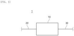
- a water purifier including an inlet flow path configured to be fluidly connected to the outside to receive a fluid; a cooling device configured to be fluidly connected to the inlet flow path to cool the received fluid; and an outlet flow path configured to be fluidly connected to the cooling device to discharge the cooled fluid to the outside, wherein the cooling device includes a cooling flow path configured to be fluidly connected to each of the inlet flow path and the outlet flow path; a cooling frame configured to be in contact with the cooling flow path and exchange heat to cool the fluid flowing in the cooling flow path; and a cooling module configured to be coupled with the cooling frame to receive heat transferred to the cooling frame and cool the cooling frame, wherein the cooling flow path includes a first cooling flow path configured to be wound around the outside of the cooling frame and be fluidly connected to one of the inlet flow path and the outlet flow path; and a second cooling flow path configured to be wound around the inside of the cooling frame and be fluidly connected to the other of the inlet flow path and the outlet flow path and
- a water purifier may be provided wherein the cooling frame is configured to extend along a first direction, and the first cooling flow path is configured in a spiral shape axially in the first direction, and wherein the flow path seat includes a concave configured to extend in a spiral shape axially in the first direction and be recessed on the outer circumference of the cooling frame to at least partially accommodate the first cooling flow path.
- a water purifier may be provided wherein the flow path seat is further configured on an inner circumference of the cooling frame, the cooling frame is configured to extend along a first direction, the second cooling flow path is configured in a spiral shape axially in the first direction, and the flow path seat includes a concave configured to extend in a spiral shape axially in the first direction and be recessed on an inner circumference of the cooling frame to at least partially accommodate the second cooling flow path.
- the cooling device and the water purifier including the same may cool and discharge a fluid without a process of storing the fluid.
- the cooling module When the cooling module is operated, the heat of the cooling frame and the cooling flow path coupled thereto is transferred to the cooling module. Accordingly, fluid flowing along the cooling flow path may also be cooled while transferring heat to the cooling module. That is, the cooling process of the fluid may be performed while the fluid flows along the cooling flow path.
- the introduced fluid may be flowed, cooled and discharged without having a separate configuration for storing and cooling the fluid. Accordingly, the cooling device and the water purifier may be miniaturized, and the cooled fluid may be rapidly discharged and provided to the user.
- the cooling device and the water purifier including the same according to the embodiment of the present disclosure may increase heat-exchange time to improve cooling efficiency.
- the cooling flow path may include a plurality of flow paths.
- the cooling flow path may include a first cooling flow path wound around an outer circumference of the cooling frame and a second cooling flow path wound around an inner circumference of the cooling frame.
- the first cooling flow path and the second cooling flow path are fluidly connected to each other. The fluid introduced into one cooling flow path may flow out through the other cooling flow path.
- the second cooling flow path is fluidly connected to the first cooling flow path.
- the fluid flowing along the first cooling flow path and cooled, or the fluid introduced from the outside may flow along the second cooling flow path and be cooled by heat-exchange with the inner circumference of the cooling frame.
- the cooling device and the water purifier including the same may increase a contact area between a member in which a fluid flows and a member for cooling the fluid to improve cooling efficiency.
- At least one of the inner and outer flow paths constituting the first cooling flow path may be configured in an elliptical shape in which the length of the diameter in one direction is longer than the length of the diameter in the other direction.
- one side where the outer flow path and the inner flow path are in contact with each other or one side where the inner flow path is in contact with an outer circumference of the cooling frame may be configured as a smooth curved surface corresponding to the major axis.
- the outer flow path and the inner flow path or the inner flow path and the outer circumference of the cooling frame may be in surface contact, so that a contact area may be increased. Accordingly, the contact area between the outer flow path, the inner flow path, and the cooling frame may be increased, thereby improving the cooling efficiency of the fluid.
- a flow path seat may be formed on an outer circumference or an inner circumference of the cooling frame.
- the flow path seat includes a concave recessed and a convex surrounding the concave.
- the concave accommodates an inner flow path or a second cooling flow path.
- the concave may be configured to correspond to the shape of the inner flow path or the second cooling flow path, and the convex may be in surface contact with the inner flow path or the second cooling flow path accommodated in the concave.
- the contact area between the inner flow path and the outer circumference of the cooling frame or the second cooling flow path and the inner circumference of the cooling frame may be increased, thereby improving the cooling efficiency of the fluid.
- the cooling device and the water purifier including the same may discharge a sufficient amount of cold-water during one water discharge.
- the cooling flow path may include a first cooling flow path wound around the outer circumference of the cooling frame and a second cooling flow path wound around the inner circumference of the cooling frame.
- the first cooling flow path may include an inner flow path directly in contact with the outer circumference of the cooling frame and an outer flow path wound around the inner flow path.
- the first cooling flow path and the second cooling flow path are fluidly connected to each other.
- the fluid introduced into one of the first cooling flow path and the second cooling flow path may be discharged to the outside through the other one. That is, the introduced fluid may be discharged to the outside after passing through all the first cooling flow path and the second cooling flow path and cooling.
- the fluid as much as the volume of a first cooling hollow formed in the first cooling flow path and a second cooling hollow formed in the second cooling flow path may be cooled at the same time and discharged continuously. Therefore, a sufficient amount of cold-water may be discharged during one water discharge.
- the cooling device and the water purifier including the same according to the embodiment of the present disclosure may improve assembly convenience.
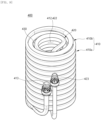
- the first cooling flow path 410 forms a portion of the cooling flow path 400.
- the first cooling flow path 410 forms one of the inlet flow path and the outlet flow path of the fluid.
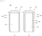
- the first cooling flow path 410 may be wound around the outer circumference of the cooling body 310, and the first cooling flow path 410 and the fluid flowing therein may exchange heat with the cooling body 310 to be cooled.
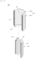
- the first cooling flow path 410 may extend in a spiral shape.
- the first cooling flow path 410 may be divided into a plurality of portions.
- the plurality of portions may be disposed to overlap along the radial direction.
- a first portion of the plurality of portions constituting the first cooling flow path 410 are directly wound around the outer circumference of the cooling body 310, and a second portion of the plurality of portions are indirectly wound around the outer circumference of the cooling body 310 through the first portion.
- the first cooling flow path 410 includes an outer flow path 410a located radially outside and an inner flow path 410b located radially inside.
- the inner flow path 410b is directly wound around the outer circumference of the cooling body 310.
- the outer flow path 410a is located radially outside the inner flow path 410b, and is indirectly wound around the outer circumference of the cooling body 310 through the inner flow path 410b. At this time, the outer flow path 410a and the inner flow path 410b are fluidly connected to each other.
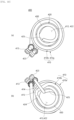
- the practical benefit of distinguishing the outer flow path 410a and the inner flow path 410b lies in the shapes of the outer flow path 410a and the inner flow path 410b.
- the outer flow path 410a may be configured such that its cross-section has a diameter in one direction greater than a diameter in the other direction.
- the outer flow path 410a is configured to have an elliptical cross-section in which the up and down direction is major axis and the radiation direction is minor axis.
- each side of the outer flow path 410a toward the inner flow path 410b is formed with a relatively gentle curved surface. Accordingly, the outer flow path 410a and the inner flow path 410b may be in surface contact.
- the contact area between the outer flow path 410a and the inner flow path 410b may be increased, thereby improving the heat-exchange efficiency of the cooling frame 300 with the fluid flowing in the outer flow path 410a, which is indirectly wound around the cooling body 310.
- the inner flow path 410b may be configured to have a circular cross-section corresponding to the shape of the flow path seat 340.
- the outer circumference of the inner flow path 410b may be at least partially in surface contact with the convex 342.
- the contact area between the inner flow path 410b and the outer circumference of the cooling body 310 may be increased, thereby improving the heat-exchange efficiency of the fluid flowing in the inner flow path 410b and the cooling frame 300.
- the flow path seat 340 may also be changed to correspond to the shape of the inner flow path 410b. Accordingly, the flow path seat 340 and the convex 342 are also in surface contact with the inner flow path 410b, and the cooling efficiency of the fluid flowing inside the inner flow path 410b may be improved.
- the inner flow path 410b may be accommodated in the concave 341 to be in surface contact with the convex 342, and may be in line contact with the outer circumference of the cooling body 310 at the remaining height, that is, a height corresponding to the difference between the first height H1 and the second height H2.
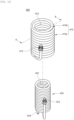
- the first cooling flow path 410 includes a first cooling hollow 411, a first cooling space 412, a first cooling communicator 413, a first connector 414 and a flow path coupler 415.
- the first cooling hollow 411 is a space formed inside the first cooling flow path 410.
- the first cooling hollow 411 is configured to extend along the first cooling flow path 410.
- Each end of the first cooling hollow 411 may be opened and fluidly connected to another member.
- one end of the first cooling hollow 411 is fluidly connected to the first cooling communicator 413, and the other end of the first cooling hollow 411 is fluidly connected to the second cooling flow path 420.
- the first cooling hollow 411 may have a shape corresponding to the shape of the first cooling flow path 410.
- the first cooling flow path 410 includes the outer flow path 410a and the inner flow path 410b. Accordingly, the first cooling hollow 411 located inside the outer flow path 410a may be configured such that its cross-section has a diameter in one direction greater than a diameter in the other direction.
- the first cooling hollow 411 located inside the inner flow path 410b may have a circular cross-section.
- the first cooling space 412 is a space formed radially inwardly of the first cooling flow path 410 extending in a spiral shape.
- the first cooling space 412 accommodates the cooling frame 300 and the second cooling flow path 420.
- the first cooling space 412 may be configured to correspond to the shape of the first cooling flow path 410.
- the first cooling space 412 has a cylindrical shape with a circular cross-section and a height in the up and down direction.
- the radial direction of the first cooling space 412 is surrounded by the inner flow path 410b.
- Each end of the first cooling space 412 in the height direction, that is, the upper side and the lower side in the illustrated embodiment, are respectively configured as open.
- the diameter of the cross-section of the first cooling space 412 may be greater than the diameter of the cross-section of the cooling body 310.
- the first cooling flow path 410 may be pressurized radially outwardly, and the cooling body 310 may be accommodated after the diameter of the cross-section of the first cooling space 412 is increased. Thereafter, when the pressurized state of the first cooling flow path 410 is released, the diameter of the cross-section of the first cooling space 412 is reduced, so that the inner flow path 410b may be fitted into and coupled with the cooling body 310.
- the first cooling communicator 413 is a portion in which the first cooling flow path 410 is fluidly connected to the outside.
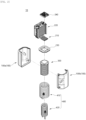
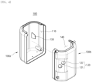
- the first cooling communicator 413 is coupled with the communicator 120 formed in the frame 100 and exposed to the outside of the frame 100.
- the first cooling communicator 413 is fluidly connected to one end of the first cooling flow path 410 in the extension direction, that is, the left end of the illustrated embodiment.
- the first cooling communicator 413 may be fluidly connected to either the inlet flow path 20 or the outlet flow path 30. In an embodiment in which the first cooling communicator 413 is fluidly connected to the inlet flow path 20, the first cooling flow path 410 may form an inlet flow path of the fluid. In an embodiment in which the first cooling communicator 413 is fluidly connected to the outlet flow path 30, the first cooling flow path 410 may form an outlet flow path of the fluid.
- the first cooling communicator 413 may be coupled with the first communicator 121.
- the first cooling communicator 413 may be coupled with the first communicator 121 through.
- the first cooling communicator 413 may be configured to correspond to the shape of the first communicator 121 to close the first communicator 121. Accordingly, arbitrary communication between the frame space 110 and the outside may be blocked.
- the first cooling communicator 413 is fluidly connected to the outer flow path 410a.
- the fluid introduced into the first cooling communicator 413 may flow to the inner flow path 410b through the outer flow path 410a.
- the fluid introduced into the outer flow path 410a may flow out to the outside through the first cooling communicator 413.
- the first connector 414 forms the other end portion of the first cooling flow path 410 in the extended direction.
- the first connector 414 is a portion in which the first cooling flow path 410 is fluidly connected to the second cooling flow path 420.
- the first connector 414 forms a lower end of the first cooling flow path 410.
- the heat-exchange time between the fluid flowing along the first cooling flow path 410 and the cooling frame 300 may be increased thereby improving the cooling efficiency of the fluid. A detailed description thereof will be given later.
- the first connector 414 is fluidly connected to the second connector 424 of the second cooling flow path 420 through the flow path coupler 415.
- the flow path coupler 415 fluidly connects the first cooling flow path 410 and the second cooling flow path 420.
- the flow path coupler 415 is coupled with the first connector 414 of the first cooling flow path 410 and the second connector 424 of the second cooling flow path 420, respectively.
- the flow path coupler 415 is fluidly connected to the first connector 414 and the second connector 424, respectively.
- the flow path coupler 415 may be disposed at a position corresponding to the positions of the first connector 414 and the second connector 424. In the illustrated embodiment, the flow path coupler 415 is located biased to the lower side of the cooling flow path 400.
- the second cooling flow path 420 forms the other portion of the cooling flow path 400.
- the second cooling flow path 420 forms the other of the inlet flow path and the outlet flow path of the fluid.
- the second cooling flow path 420 is accommodated in the accommodation space 330.
- the second cooling flow path 420 may be wound around the inner circumference of the cooling body 310, and the second cooling flow path 420 and the fluid flowing therein may exchange heat with the cooling body 310 to be cooled.
- the second cooling flow path 420 may extend in a spiral shape.
- the flow path seat 340 may be formed only as much as the second height H2 from the lower side on the inner circumference of the cooling body 310. Accordingly, the second cooling flow path 420 may be coupled with the flow path seat 340 formed on the lower side and may be wound around the cooling body 310.
- the second cooling flow path 420 may be accommodated in the concave 341 extending in a spiral shape along the inner circumference of the cooling body 310 and may be in surface contact with the convex 342.
Landscapes
- Engineering & Computer Science (AREA)
- Physics & Mathematics (AREA)
- Thermal Sciences (AREA)
- Mechanical Engineering (AREA)
- General Engineering & Computer Science (AREA)
- Chemical & Material Sciences (AREA)
- Combustion & Propulsion (AREA)
- Cooling Or The Like Of Semiconductors Or Solid State Devices (AREA)
- Devices That Are Associated With Refrigeration Equipment (AREA)
Applications Claiming Priority (2)
| Application Number | Priority Date | Filing Date | Title |
|---|---|---|---|
| KR1020220145082A KR20240063449A (ko) | 2022-11-03 | 2022-11-03 | 냉각 장치 및 이를 포함하는 정수기 |
| PCT/KR2023/013024 WO2024096288A1 (ko) | 2022-11-03 | 2023-08-31 | 냉각 장치 및 이를 포함하는 정수기 |
Publications (2)
| Publication Number | Publication Date |
|---|---|
| EP4579162A1 true EP4579162A1 (de) | 2025-07-02 |
| EP4579162A4 EP4579162A4 (de) | 2025-12-10 |
Family
ID=90930763
Family Applications (1)
| Application Number | Title | Priority Date | Filing Date |
|---|---|---|---|
| EP23885985.4A Pending EP4579162A4 (de) | 2022-11-03 | 2023-08-31 | Kühlvorrichtung und wasserreiniger damit |
Country Status (3)
| Country | Link |
|---|---|
| EP (1) | EP4579162A4 (de) |
| KR (1) | KR20240063449A (de) |
| WO (1) | WO2024096288A1 (de) |
Families Citing this family (1)
| Publication number | Priority date | Publication date | Assignee | Title |
|---|---|---|---|---|
| US20240409389A1 (en) * | 2023-06-12 | 2024-12-12 | Ember Technologies, Inc. | Chilled beverage dispensing system |
Family Cites Families (8)
| Publication number | Priority date | Publication date | Assignee | Title |
|---|---|---|---|---|
| US4934150A (en) * | 1988-12-12 | 1990-06-19 | The Cornelius Company | Method and apparatus for controlling ice thickness |
| KR20040078312A (ko) * | 2003-03-03 | 2004-09-10 | 주식회사 영우워터라인 | 냉수와 온수를 실시간으로 제공하는 냉온정수기 |
| KR101435108B1 (ko) | 2013-01-30 | 2014-08-29 | 주식회사 레보테크 | 정수기용 열전소자를 이용한 직냉 타입 모듈 |
| KR20150111389A (ko) * | 2014-03-20 | 2015-10-06 | 주식회사 대유위니아 | 냉온 정수기 |
| CN107003057B (zh) * | 2014-12-05 | 2020-03-06 | 豪威株式会社 | 冷水产生罐和配备有冷水产生罐的水冷却器 |
| KR20170008339A (ko) | 2015-07-13 | 2017-01-24 | 에스케이하이닉스 주식회사 | 메모리 시스템 및 메모리 시스템의 동작 방법 |
| KR20170083399A (ko) | 2016-01-08 | 2017-07-18 | 주식회사 리빙케어 | 빙축열을 이용한 냉각 유닛 |
| KR102565252B1 (ko) * | 2021-03-15 | 2023-08-14 | 주식회사 에스앤아이 | 물이 저장되지 않는 정수기용 냉각 장치 |
-
2022
- 2022-11-03 KR KR1020220145082A patent/KR20240063449A/ko active Pending
-
2023
- 2023-08-31 WO PCT/KR2023/013024 patent/WO2024096288A1/ko not_active Ceased
- 2023-08-31 EP EP23885985.4A patent/EP4579162A4/de active Pending
Also Published As
| Publication number | Publication date |
|---|---|
| EP4579162A4 (de) | 2025-12-10 |
| WO2024096288A1 (ko) | 2024-05-10 |
| KR20240063449A (ko) | 2024-05-10 |
Similar Documents
| Publication | Publication Date | Title |
|---|---|---|
| KR102023619B1 (ko) | 냉수탱크 및 이를 구비하는 수처리 기기 | |
| US6499534B1 (en) | Heat exchanger with two-stage heat transfer | |
| EP2693152B1 (de) | Ultrareiner Inline-Wärmetauscher | |
| EP4579162A1 (de) | Kühlvorrichtung und wasserreiniger damit | |
| KR20180045754A (ko) | 언더 싱크형 먹는물 공급장치 | |
| KR100786127B1 (ko) | 온도조절장치 | |
| US20090235686A1 (en) | Fluid temperature regulator | |
| EP4253311B1 (de) | Vorrichtung zur erzeugung von kaltwasser und wasserreiniger damit | |
| EP4585874A1 (de) | Kühlvorrichtung und steuerungsverfahren dafür | |
| CN101329992B (zh) | 流体温度调整设备 | |
| CN218500499U (zh) | 一种净热一体机 | |
| CN220982015U (zh) | 换热器及净水机 | |
| CN223807653U (zh) | 一种换热装置 | |
| CN212132903U (zh) | 一种热交换单元、装置及其构成的温开水机 | |
| CN114766912B (zh) | 供水设备 | |
| CN219869249U (zh) | 一种换热装置 | |
| CN218821777U (zh) | 一种换热装置 | |
| CN217447392U (zh) | 饮水设备 | |
| CN222397980U (zh) | 一种内置液冷换热管的电热水壶 | |
| KR20250132042A (ko) | 냉수 생성 장치 | |
| CN223318520U (zh) | 一种防烫温控龙头 | |
| CN218821776U (zh) | 一种换热装置 | |
| CN218821778U (zh) | 一种热交换罐 | |
| ES2328026T3 (es) | Intercambiador de calor metodo para llevar a cabo reacciones quimicas en condiciones pseudo-isotermicas. | |
| CN218507578U (zh) | 一种水路结构 |
Legal Events
| Date | Code | Title | Description |
|---|---|---|---|
| STAA | Information on the status of an ep patent application or granted ep patent |
Free format text: STATUS: THE INTERNATIONAL PUBLICATION HAS BEEN MADE |
|
| PUAI | Public reference made under article 153(3) epc to a published international application that has entered the european phase |
Free format text: ORIGINAL CODE: 0009012 |
|
| STAA | Information on the status of an ep patent application or granted ep patent |
Free format text: STATUS: REQUEST FOR EXAMINATION WAS MADE |
|
| 17P | Request for examination filed |
Effective date: 20250326 |
|
| AK | Designated contracting states |
Kind code of ref document: A1 Designated state(s): AL AT BE BG CH CY CZ DE DK EE ES FI FR GB GR HR HU IE IS IT LI LT LU LV MC ME MK MT NL NO PL PT RO RS SE SI SK SM TR |
|
| STAA | Information on the status of an ep patent application or granted ep patent |
Free format text: STATUS: EXAMINATION IS IN PROGRESS |
|
| A4 | Supplementary search report drawn up and despatched |
Effective date: 20251106 |
|
| RIC1 | Information provided on ipc code assigned before grant |
Ipc: F25D 31/00 20060101AFI20251031BHEP Ipc: F25B 21/02 20060101ALI20251031BHEP Ipc: F25D 23/00 20060101ALI20251031BHEP Ipc: F28D 1/047 20060101ALI20251031BHEP Ipc: B67D 1/08 20060101ALI20251031BHEP |
|
| 17Q | First examination report despatched |
Effective date: 20251118 |
|
| DAV | Request for validation of the european patent (deleted) | ||
| DAX | Request for extension of the european patent (deleted) |